WO2016199422A1 - 排気ディフューザ - Google Patents
排気ディフューザ Download PDFInfo
- Publication number
- WO2016199422A1 WO2016199422A1 PCT/JP2016/002794 JP2016002794W WO2016199422A1 WO 2016199422 A1 WO2016199422 A1 WO 2016199422A1 JP 2016002794 W JP2016002794 W JP 2016002794W WO 2016199422 A1 WO2016199422 A1 WO 2016199422A1
- Authority
- WO
- WIPO (PCT)
- Prior art keywords
- inner cylinder
- outer cylinder
- cylinder
- strut
- step portion
- Prior art date
- Legal status (The legal status is an assumption and is not a legal conclusion. Google has not performed a legal analysis and makes no representation as to the accuracy of the status listed.)
- Ceased
Links
Images




Classifications
-
- F—MECHANICAL ENGINEERING; LIGHTING; HEATING; WEAPONS; BLASTING
- F01—MACHINES OR ENGINES IN GENERAL; ENGINE PLANTS IN GENERAL; STEAM ENGINES
- F01D—NON-POSITIVE DISPLACEMENT MACHINES OR ENGINES, e.g. STEAM TURBINES
- F01D25/00—Component parts, details, or accessories, not provided for in, or of interest apart from, other groups
- F01D25/30—Exhaust heads, chambers, or the like
-
- F—MECHANICAL ENGINEERING; LIGHTING; HEATING; WEAPONS; BLASTING
- F01—MACHINES OR ENGINES IN GENERAL; ENGINE PLANTS IN GENERAL; STEAM ENGINES
- F01D—NON-POSITIVE DISPLACEMENT MACHINES OR ENGINES, e.g. STEAM TURBINES
- F01D25/00—Component parts, details, or accessories, not provided for in, or of interest apart from, other groups
- F01D25/16—Arrangement of bearings; Supporting or mounting bearings in casings
- F01D25/162—Bearing supports
-
- F—MECHANICAL ENGINEERING; LIGHTING; HEATING; WEAPONS; BLASTING
- F01—MACHINES OR ENGINES IN GENERAL; ENGINE PLANTS IN GENERAL; STEAM ENGINES
- F01D—NON-POSITIVE DISPLACEMENT MACHINES OR ENGINES, e.g. STEAM TURBINES
- F01D25/00—Component parts, details, or accessories, not provided for in, or of interest apart from, other groups
- F01D25/24—Casings; Casing parts, e.g. diaphragms, casing fastenings
-
- F—MECHANICAL ENGINEERING; LIGHTING; HEATING; WEAPONS; BLASTING
- F02—COMBUSTION ENGINES; HOT-GAS OR COMBUSTION-PRODUCT ENGINE PLANTS
- F02C—GAS-TURBINE PLANTS; AIR INTAKES FOR JET-PROPULSION PLANTS; CONTROLLING FUEL SUPPLY IN AIR-BREATHING JET-PROPULSION PLANTS
- F02C7/00—Features, components parts, details or accessories, not provided for in, or of interest apart form groups F02C1/00 - F02C6/00; Air intakes for jet-propulsion plants
-
- F—MECHANICAL ENGINEERING; LIGHTING; HEATING; WEAPONS; BLASTING
- F05—INDEXING SCHEMES RELATING TO ENGINES OR PUMPS IN VARIOUS SUBCLASSES OF CLASSES F01-F04
- F05D—INDEXING SCHEME FOR ASPECTS RELATING TO NON-POSITIVE-DISPLACEMENT MACHINES OR ENGINES, GAS-TURBINES OR JET-PROPULSION PLANTS
- F05D2220/00—Application
- F05D2220/30—Application in turbines
- F05D2220/32—Application in turbines in gas turbines
-
- F—MECHANICAL ENGINEERING; LIGHTING; HEATING; WEAPONS; BLASTING
- F05—INDEXING SCHEMES RELATING TO ENGINES OR PUMPS IN VARIOUS SUBCLASSES OF CLASSES F01-F04
- F05D—INDEXING SCHEME FOR ASPECTS RELATING TO NON-POSITIVE-DISPLACEMENT MACHINES OR ENGINES, GAS-TURBINES OR JET-PROPULSION PLANTS
- F05D2230/00—Manufacture
- F05D2230/20—Manufacture essentially without removing material
- F05D2230/23—Manufacture essentially without removing material by permanently joining parts together
- F05D2230/232—Manufacture essentially without removing material by permanently joining parts together by welding
Definitions
- the present invention relates to an exhaust diffuser.
- Patent Document 1 discloses an exhaust diffuser incorporated in a gas turbine engine.
- the exhaust diffuser disclosed in Patent Document 1 includes an inner cylinder and an outer cylinder having a linear cross section from the front end to the rear end. Between the inner cylinder and the outer cylinder, an exhaust passage that extends from the front toward the rear is formed. Each of the inner cylinder and the outer cylinder is manufactured by sheet metal processing, and has a relatively thin plate thickness.
- a diffuser casing (structure) is disposed as a strength member outside the outer cylinder.
- the bearing support which supports a rotor via a bearing is arrange
- the bearing support and the structure are connected by a plurality of struts that penetrate the inner cylinder and the outer cylinder.
- each strut is surrounded by a strut cover between the inner cylinder and the outer cylinder in order to prevent the strut from being directly heated by the exhaust.
- Cross-sectional area of exhaust flow path refers to the cross section where the exhaust flow path is minimized (the cross section along the line connecting the contact points of the inner cylinder and the outer cylinder in the sphere that contacts the inner cylinder and the outer cylinder in the exhaust flow path) ) The area above.
- the cross-sectional area of the exhaust passage changes rapidly in the vicinity of the front and rear edges of the strut cover.
- Patent Document 2 discloses that only a portion where the strut cover in the inner cylinder and the outer cylinder is joined is provided with a strut cover. The formation of the same number of local recesses is described.
- the present invention can alleviate a sudden change in the cross-sectional area of the exhaust flow path caused by the strut cover in the vicinity of the front edge and the rear edge of the strut cover, and the inner cylinder and the outer cylinder are processed by sheet metal processing.
- An object of the present invention is to provide an exhaust diffuser that can be easily manufactured.
- an exhaust diffuser includes an outer cylinder that forms an exhaust passage that extends from the front toward the rear between the inner cylinder and the inner cylinder, A plurality of struts that pass through an inner cylinder and the outer cylinder and connect a bearing support arranged inside the inner cylinder and a structure arranged outside the outer cylinder, from the bearing support A strut that tilts backward toward the structure, and a plurality of strut covers that respectively surround the plurality of struts between the inner cylinder and the outer cylinder, and the outer cylinder includes the plurality of strut covers in an axial direction.
- a taper-shaped first step portion for expanding the diameter of the outer cylinder is provided at a position overlapping the front edge of the strut cover, and the inner cylinder is located at a position overlapping the rear edges of the plurality of strut covers in the axial direction.
- a second step portion tapered to enlarged the inner cylinder, and wherein the.
- Front and “rear” refer to one side (upstream side of exhaust flow) and the other side (downstream side of exhaust flow) of the exhaust diffuser, respectively.
- the strut cover is also inclined backward from the inner cylinder toward the outer cylinder. Therefore, the first step portion of the outer cylinder is inclined along the front edge of the strut cover, and the second step portion of the inner cylinder is inclined along the rear edge of the strut cover. For this reason, the cross-sectional area of the exhaust passage can be changed smoothly and continuously.
- the rear end of the first stepped portion coincides with the upstream end of the strut cover on the outer cylinder, and the front end of the second stepped portion coincides with the downstream end of the strut cover on the inner cylinder. It may be. According to this configuration, the strut cover, the inner cylinder, and the outer cylinder can be easily welded.
- an exhaust diffuser includes an inner cylinder, an outer cylinder that forms an exhaust passage that extends from the front toward the rear, and the inner cylinder and the outer cylinder.
- a plurality of strut covers that respectively surround the plurality of struts between the inner cylinder and the outer cylinder, and the inner cylinder includes a front edge of the plurality of strut covers in the axial direction.
- a taper-shaped first step portion for reducing the diameter of the inner cylinder is provided at the overlapping position, and the outer cylinder is contracted to a position where it overlaps the rear edges of the plurality of strut covers in the axial direction.
- the strut cover is also inclined forward from the inner cylinder toward the outer cylinder. Therefore, the first step portion of the inner cylinder is inclined along the front edge of the strut cover, and the second step portion of the outer cylinder is inclined along the rear edge of the strut cover. For this reason, the cross-sectional area of the exhaust passage can be changed smoothly and continuously.
- the rear end of the first stepped portion is coincident with the upstream end of the strut cover on the inner cylinder, and the front end of the second stepped portion is the outer cylinder. It may coincide with the downstream end of the upper strut cover. According to this configuration, the strut cover, the inner cylinder, and the outer cylinder can be easily welded.
- a sudden change in the cross-sectional area of the exhaust passage caused by the strut cover in the vicinity of the front edge and the rear edge of the strut cover can be mitigated, and the inner cylinder and the outer cylinder are processed by sheet metal processing. Can be manufactured more easily.
- FIG. 3 is a sectional view taken along line III-III in FIG. 2. It is a sectional view of a part of the exhaust diffuser of the first modification. It is sectional drawing of a part of exhaust diffuser of a 2nd modification. It is a sectional view of a part of an exhaust diffuser according to a second embodiment of the present invention.
- FIG. 1 shows a gas turbine engine 1 in which an exhaust diffuser 2A according to a first embodiment of the present invention is incorporated.
- an exhaust diffuser 2A according to a first embodiment of the present invention is incorporated.
- one of the exhaust diffusers 2A in the axial direction is referred to as the front, and the other (downstream side of the exhaust flow) is referred to as the rear.
- the gas turbine engine 1 includes a compressor casing 14, a main housing 15, a turbine casing 16, and a diffuser casing 17 (corresponding to the structure of the present invention).
- the turbine casing 16 is disposed in the main housing 15, and the diffuser casing 17 is connected to the main housing 15.
- the rotor 11 is disposed in the compressor casing 14 and the turbine casing 16 so as to penetrate these casings.
- the front end portion of the rotor 11 is supported by a bearing support 19 via a bearing 18, and the rear end portion of the rotor 11 is supported by a bearing support 13 via a bearing 12.
- the exhaust diffuser 2A includes an inner cylinder 3, an outer cylinder 4, and a plurality of struts 5.
- An exhaust passage 21 is formed between the inner cylinder 3 and the outer cylinder 4 so as to expand from the front toward the rear.
- both the inner cylinder 3 and the outer cylinder 4 are enlarged from the front toward the rear.
- the above-described bearing support 13 is disposed inside the inner cylinder 3, and the above-described diffuser casing 17 is disposed outside the outer cylinder 4.
- the inner cylinder 3 is divided into a front piece 31 and a rear piece 32
- the outer cylinder 4 is divided into a front piece 41 and a rear piece 42.
- each of the inner cylinder 3 and the outer cylinder 4 may be a single member.
- the front end portion of the front piece 31 of the inner cylinder 3 is connected to the bearing support 13 via the bracket 71. Further, the rear end portion of the front piece 31 is connected to the front end portion of the rear piece 32.
- the front end portion of the front piece 41 of the outer cylinder 4 is fixed to the diffuser casing 17 via a bracket 72, and the rear end portion of the front piece 41 is fixed to the diffuser casing 17 via a bracket 73.
- a bracket 74 is joined to the rear piece 42 of the outer cylinder 4 by welding, for example, and the bracket 74 is fixed to the diffuser casing 17.
- Each strut 5 passes through the front piece 31 of the inner cylinder 3 and the front piece 41 of the outer cylinder 4 to connect the bearing support 13 and the diffuser casing 17.
- Each strut 5 is inclined rearward from the bearing support 13 toward the diffuser casing 17.
- Each strut 5 has a flat plate shape in the exhaust flow direction.
- all the struts 5 are arranged on the same circumference so as to completely overlap in the circumferential direction.
- the struts 5 may be arranged in a staggered manner so that adjacent struts 5 partially overlap in the circumferential direction.
- All struts 5 are surrounded by a plurality of strut covers 6 between the inner cylinder 3 and the outer cylinder 4.
- Each strut cover 6 has a slightly larger cross-sectional shape than the strut 5, and extends parallel to the strut 5. In other words, each strut cover 6 is inclined backward from the inner cylinder 3 toward the outer cylinder 4.
- Each strut cover 6 is joined to the front piece 31 of the inner cylinder 3 and the front piece 41 of the outer cylinder 4 by welding, for example.
- the outer cylinder 4 has a tapered first step portion 43 at a position overlapping the front edge 61 of the strut cover 6 in the axial direction.
- the first step portion 43 cancels the reduction in the cross-sectional area of the exhaust flow path 21 caused by the strut cover 6 from the upstream side to the downstream side of the front edge 61 of the strut cover 6 (it is not necessarily required to be zero).
- the outer cylinder 4 is expanded in diameter over the entire circumference.
- the cross-sectional shape of the inner peripheral surface of the outer cylinder 4 is linear in front of the first step portion 43, in the first step portion 43, and behind the first step portion 43. For this reason, the shape of the outer cylinder 4 is simple.
- the cross-sectional shape of the inner peripheral surface of the outer cylinder 4 will be described in more detail.
- the front inclination angle of the first step portion 43 (the angle with respect to the axial direction of the exhaust diffuser 2A) is equal to the rear inclination angle of the first step portion 43.
- the inclination angle of the first step part 43 is larger than the inclination angle of the front and rear of the first step part 43.
- the tapered first step portion 43 may be curved.
- the inner cylinder 3 has a tapered second step portion 33 at a position overlapping the rear edge 62 of the strut cover 6 in the axial direction.
- the second step portion 33 cancels the increase in the cross-sectional area of the exhaust passage 21 caused by the strut cover 6 from the upstream side to the downstream side of the rear edge 62 of the strut cover 6 (it is not necessarily required to be zero).
- the inner cylinder 3 is expanded in diameter over the entire circumference.
- the cross-sectional shape of the outer peripheral surface of the inner cylinder 3 is linear in front of the second stepped portion 33, in the second stepped portion 33, and behind the second stepped portion 33. For this reason, the shape of the inner cylinder 3 is simple.
- the cross-sectional shape of the inner peripheral surface of the inner cylinder 3 will be described in more detail.
- the front inclination angle of the second step portion 33 (the angle with respect to the axial direction of the exhaust diffuser 2A) is equal to the rear inclination angle of the second step portion 33.
- the inclination angle of the second step portion 33 is larger than the inclination angle of the front and rear of the second step portion 33.
- the tapered second stepped portion 33 may be curved.
- the front end 44 of the first stepped portion 43 is located in front of the upstream end 6 a of the strut cover 6 on the inner cylinder 3 (the inner end of the front edge 61).
- the rear end 35 is located behind the downstream end 6d of the strut cover 6 on the outer cylinder 4 (the outer end of the rear edge 62).
- the rear end 45 of the first stepped portion 43 coincides with the upstream end 6c of the strut cover 6 on the outer cylinder 4 (the outer end of the front edge 61), and the front end 34 of the second stepped portion 33 is It coincides with the downstream end 6b of the strut cover 6 on the cylinder 3 (the inner end of the trailing edge 62).
- the strut cover 6, the inner cylinder 3, and the outer cylinder 4 can be easily welded.
- the rear end 45 of the first stepped portion 43 may be located in front of the upstream end 6 c of the strut cover 6 on the outer cylinder 4.
- the distance from the inner cylinder 3 to the outer cylinder 4 is in the section from the first step portion 43 of the outer cylinder 4 to the second step portion 33 of the inner cylinder 3. Partially enlarged. For this reason, the rapid change of the cross-sectional area of the exhaust flow path 21 resulting from the strut cover 6 in the vicinity of the front edge 61 and the rear edge 62 of the strut cover 6 can be reduced. And since it is not necessary to form a recessed part in each of the inner cylinder 3 and the outer cylinder 4, the inner cylinder 3 and the outer cylinder 4 can be manufactured easily by sheet metal processing.
- the strut cover 6 is inclined backward from the inner cylinder 3 toward the outer cylinder 4. Accordingly, the first step 43 of the outer cylinder 4 is inclined along the front edge 61 of the strut cover 6, and the second step 33 of the inner cylinder 3 is inclined along the rear edge 62 of the strut cover 6. For this reason, the cross-sectional area of the exhaust passage 21 can be changed smoothly and continuously.
- the front end 44 of the first step 43 is positioned forward of the upstream end 6 a of the strut cover 6 on the inner cylinder 3, so that the upstream end 6 a of the strut cover 6 on the inner cylinder 3.
- the detour flow along the front edge 61 of the strut cover 6 can be formed even in the vicinity of the.
- the rear end 35 of the second stepped portion 33 is located behind the downstream end 6 d of the strut cover 6 on the outer cylinder 4, exhaust is also performed in the vicinity of the downstream end 6 d of the strut cover 6 on the outer cylinder 4. Peeling can be suppressed.
- both the inner cylinder 3 and the outer cylinder 4 are enlarged from the front to the rear.
- the inner cylinder 3 and the outer cylinder 4 have the exhaust passage 21 formed between them from the front. Any shape may be used as long as it spreads backward.
- the inner cylinder 3 may be straight except for the second step portion 33.
- the outer cylinder 4 may be straight except for the first step portion 43, and the inner cylinder 3 may be reduced from the front toward the rear.
- both the inner cylinder 3 and the outer cylinder 4 may be reduced from the front toward the rear.
- both the inner cylinder 3 and the outer cylinder 4 expand from the front toward the rear.
- the inner cylinder 3 and the outer cylinder 4 have any shape as long as the exhaust passage 21 formed between them expands from the front toward the rear. It may be.
- each strut cover 6 is also inclined forward from the inner cylinder 3 toward the outer cylinder 4.
- the inner cylinder 3 has a tapered first step portion 36 at a position overlapping the front edge 61 of the strut cover 6 in the axial direction.
- the first step portion 36 cancels the reduction in the cross-sectional area of the exhaust passage 21 caused by the strut cover 6 from the upstream side to the downstream side of the front edge 61 of the strut cover 6 (it is not necessarily required to be zero).
- the inner cylinder 3 is reduced in diameter over the entire circumference.
- the cross-sectional shape of the outer peripheral surface of the inner cylinder 3 is linear in front of the first step portion 36, in the first step portion 36, and behind the first step portion 36. For this reason, the shape of the inner cylinder 3 is simple.
- the cross-sectional shape of the inner peripheral surface of the inner cylinder 3 will be described in more detail.
- a front inclination angle of the first step portion 36 (an angle with respect to the axial direction of the exhaust diffuser 2B) is equal to a rear inclination angle of the first step portion 36.
- the inclination angle of the first step portion 36 is smaller than the front and rear inclination angles of the first step portion 36 (minus in some cases).
- the tapered first step portion 36 may be curved.
- the outer cylinder 4 has a tapered second step portion 46 at a position overlapping the rear edge 62 of the strut cover 6 in the axial direction.
- the second stepped portion 46 cancels the increase in the cross-sectional area of the exhaust passage 21 caused by the strut cover 6 from the upstream side to the downstream side of the rear edge 62 of the strut cover 6 (it is not necessarily required to be zero).
- the outer cylinder 4 is reduced in diameter over the entire circumference.
- the cross-sectional shape of the inner peripheral surface of the outer cylinder 4 is linear in front of the second stepped portion 46, in the second stepped portion 46, and behind the second stepped portion 46. For this reason, the shape of the outer cylinder 4 is simple.
- the cross-sectional shape of the inner peripheral surface of the outer cylinder 4 will be described in more detail.
- the front inclination angle of the second step portion 46 (the angle with respect to the axial direction of the exhaust diffuser 2B) is equal to the rear inclination angle of the second step portion 46.
- the inclination angle of the second step portion 46 is smaller than the inclination angle of the front and rear of the second step portion 46 (in some cases, minus).
- the tapered second stepped portion 46 may be curved.
- the front end 37 of the first step portion 36 is positioned in front of the upstream end 6 c of the strut cover 6 on the outer cylinder 4, and the rear end 48 of the second step portion 46 is the inner cylinder 3. It is located behind the downstream end 6 b of the upper strut cover 6. Further, the rear end 38 of the first stepped portion 36 coincides with the upstream end 6 a of the strut cover 6 on the inner cylinder 3, and the front end 47 of the second stepped portion 46 is connected to the strut cover 6 on the outer cylinder 4. It coincides with the downstream end 6d. For this reason, the strut cover 6, the inner cylinder 3, and the outer cylinder 4 can be easily welded. However, the rear end 38 of the first step portion 36 may be positioned in front of the upstream end 6 a of the strut cover 6 on the inner cylinder 3.
- the distance from the inner cylinder 3 to the outer cylinder 4 is small. Partially enlarged. For this reason, the rapid change of the cross-sectional area of the exhaust flow path 21 resulting from the strut cover 6 in the vicinity of the front edge 61 and the rear edge 62 of the strut cover 6 can be reduced. And since it is not necessary to form a recessed part in each of the inner cylinder 3 and the outer cylinder 4, the inner cylinder 3 and the outer cylinder 4 can be manufactured easily by sheet metal processing.
- the strut cover 6 is inclined forward from the inner cylinder 3 toward the outer cylinder 4. Therefore, the first step portion 36 of the inner cylinder 3 is inclined along the front edge 61 of the strut cover 6, and the second step portion 46 of the outer cylinder 4 is inclined along the rear edge 62 of the strut cover 6. For this reason, the cross-sectional area of the exhaust passage 21 can be changed smoothly and continuously.
- the front end 37 of the first stepped portion 36 is located in front of the upstream end 6 c of the strut cover 6 on the outer cylinder 4, so the upstream end 6 c of the strut cover 6 on the outer cylinder 4.
- the detour flow along the front edge 61 of the strut cover 6 can be formed even in the vicinity of the.
- the rear end 48 of the second stepped portion 46 is located behind the downstream end 6 b of the strut cover 6 on the inner cylinder 3, exhaust is also performed in the vicinity of the downstream end 6 b of the strut cover 6 on the inner cylinder 3. Peeling can be suppressed.
- the exhaust diffusers 2A and 2B are not necessarily incorporated into the gas turbine engine 1, and may be disposed, for example, downstream of the steam turbine.
- a structure other than the diffuser casing may be disposed outside the outer cylinder 4.
Landscapes
- Engineering & Computer Science (AREA)
- Mechanical Engineering (AREA)
- General Engineering & Computer Science (AREA)
- Chemical & Material Sciences (AREA)
- Combustion & Propulsion (AREA)
- Exhaust Silencers (AREA)
- Supercharger (AREA)
Abstract
Description
図1に、本発明の第1実施形態に係る排気ディフューザ2Aが組み込まれたガスタービンエンジン1を示す。以下では、排気ディフューザ2Aの軸方向の一方(排気の流れの上流側)を前方、他方(排気の流れの下流側)を後方という。
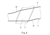
本実施形態では、内筒3と外筒4の双方が前方から後方に向かって拡大していたが、内筒3および外筒4は、それらの間に形成される排気流路21が前方から後方に向かって広がる限りどのような形状であってもよい。例えば、図4に示すように、第2段差部33以外では内筒3がストレートであってもよい。あるいは、図5に示すように、第1段差部43以外では外筒4がストレートであり、内筒3が前方から後方に向かって縮小していてもよい。さらには、内筒3と外筒4の双方が前方から後方に向かって縮小していてもよい。
次に、図6を参照して、本発明の第2実施形態に係る排気ディフューザ2Bを説明する。なお、本実施形態において、第1実施形態と同一構成要素には同一符号を付し、重複した説明は省略する。
本発明は上述した実施形態に限定されるものではなく、本発明の要旨を逸脱しない範囲で種々の変形が可能である。
17 ディフューザケーシング(構造体)
2A,2B 排気ディフューザ
21 排気流路
3 内筒
33 第2段差部
34 前端
35 後端
36 第1段差部
37 前端
38 後端
4 外筒
43 第1段差部
44 前端
45 後端
46 第2段差部
47 前端
48 後端
5 ストラット
6 ストラットカバー
6a,6c 上流端
6b,6d 下流端
61 前縁
62 後縁
Claims (4)
- 内筒と、
前記内筒との間に、前方から後方に向かって広がる排気流路を形成する外筒と、
前記内筒および前記外筒を貫通して、前記内筒の内側に配置された軸受サポートと前記外筒の外側に配置された構造体とを連結する複数のストラットであって、前記軸受サポートから前記構造体に向かって後方に傾くストラットと、
前記内筒と前記外筒との間で前記複数のストラットをそれぞれ囲繞する複数のストラットカバーと、を備え、
前記外筒は、軸方向において前記複数のストラットカバーの前縁と重なり合う位置に、当該外筒を拡径するテーパー状の第1段差部を有しており、
前記内筒は、軸方向において前記複数のストラットカバーの後縁と重なり合う位置に、当該内筒を拡径するテーパー状の第2段差部を有している、排気ディフューザ。 - 前記第1段差部の後端は、前記外筒上の前記ストラットカバーの上流端と一致しており、
前記第2段差部の前端は、前記内筒上の前記ストラットカバーの下流端と一致している、請求項1に記載の排気ディフューザ。 - 内筒と、
前記内筒との間に、前方から後方に向かって広がる排気流路を形成する外筒と、
前記内筒および前記外筒を貫通して、前記内筒の内側に配置された軸受サポートと前記外筒の外側に配置された構造体とを連結する複数のストラットであって、前記軸受サポートから前記構造体に向かって前方に傾くストラットと、
前記内筒と前記外筒との間で前記複数のストラットをそれぞれ囲繞する複数のストラットカバーと、を備え、
前記内筒は、軸方向において前記複数のストラットカバーの前縁と重なり合う位置に、当該内筒を縮径するテーパー状の第1段差部を有しており、
前記外筒は、軸方向において前記複数のストラットカバーの後縁と重なり合う位置に、当該外筒を縮径するテーパー状の第2段差部を有している、排気ディフューザ。 - 前記第1段差部の後端は、前記内筒上の前記ストラットカバーの上流端と一致しており、
前記第2段差部の前端は、前記外筒上の前記ストラットカバーの下流端と一致している、請求項3に記載の排気ディフューザ。
Priority Applications (4)
| Application Number | Priority Date | Filing Date | Title |
|---|---|---|---|
| GB1720510.5A GB2555051B (en) | 2015-06-09 | 2016-06-09 | Exhaust diffuser |
| US15/580,923 US20180328229A1 (en) | 2015-06-09 | 2016-06-09 | Exhaust diffuser |
| DE112016002592.0T DE112016002592T5 (de) | 2015-06-09 | 2016-06-09 | Abgasdiffusor |
| CN201680030910.1A CN107636260B (zh) | 2015-06-09 | 2016-06-09 | 废气扩散器 |
Applications Claiming Priority (2)
| Application Number | Priority Date | Filing Date | Title |
|---|---|---|---|
| JP2015116352A JP6498534B2 (ja) | 2015-06-09 | 2015-06-09 | 排気ディフューザ |
| JP2015-116352 | 2015-06-09 |
Publications (1)
| Publication Number | Publication Date |
|---|---|
| WO2016199422A1 true WO2016199422A1 (ja) | 2016-12-15 |
Family
ID=57503326
Family Applications (1)
| Application Number | Title | Priority Date | Filing Date |
|---|---|---|---|
| PCT/JP2016/002794 Ceased WO2016199422A1 (ja) | 2015-06-09 | 2016-06-09 | 排気ディフューザ |
Country Status (6)
| Country | Link |
|---|---|
| US (1) | US20180328229A1 (ja) |
| JP (1) | JP6498534B2 (ja) |
| CN (1) | CN107636260B (ja) |
| DE (1) | DE112016002592T5 (ja) |
| GB (1) | GB2555051B (ja) |
| WO (1) | WO2016199422A1 (ja) |
Families Citing this family (3)
| Publication number | Priority date | Publication date | Assignee | Title |
|---|---|---|---|---|
| US10563543B2 (en) * | 2016-05-31 | 2020-02-18 | General Electric Company | Exhaust diffuser |
| KR102403823B1 (ko) * | 2019-12-13 | 2022-05-30 | 두산에너빌리티 주식회사 | 스트립이 형성된 배기 디퓨져의 스트롯 구조 및 가스터빈 |
| CN114542214B (zh) * | 2022-03-09 | 2024-05-17 | 中国船舶重工集团公司第七0三研究所 | 一种船用汽轮机高可靠性空心杆支撑汽缸结构 |
Citations (4)
| Publication number | Priority date | Publication date | Assignee | Title |
|---|---|---|---|---|
| JP2005290985A (ja) * | 2003-10-09 | 2005-10-20 | Mitsubishi Heavy Ind Ltd | 軸流タービンの排気ディフューザー |
| JP2013170486A (ja) * | 2012-02-20 | 2013-09-02 | Toshiba Corp | 軸流排気タービン |
| JP2015514898A (ja) * | 2012-03-30 | 2015-05-21 | アルストム テクノロジー リミテッドALSTOM Technology Ltd | ガスタービン用の排気ディフューザ |
| US20150143816A1 (en) * | 2013-11-22 | 2015-05-28 | Anil L. Salunkhe | Modular industrial gas turbine exhaust system |
Family Cites Families (14)
| Publication number | Priority date | Publication date | Assignee | Title |
|---|---|---|---|---|
| US2930662A (en) * | 1956-11-01 | 1960-03-29 | Bristol Aero Engines Ltd | Supporting structure for a gas turbine bearing |
| SE395747B (sv) * | 1975-12-10 | 1977-08-22 | Stal Laval Turbin Ab | Tvastegsgasturbin |
| US6866479B2 (en) * | 2003-05-16 | 2005-03-15 | Mitsubishi Heavy Industries, Ltd. | Exhaust diffuser for axial-flow turbine |
| JP4040556B2 (ja) * | 2003-09-04 | 2008-01-30 | 株式会社日立製作所 | ガスタービン設備及び冷却空気供給方法 |
| JP4969500B2 (ja) * | 2008-03-28 | 2012-07-04 | 三菱重工業株式会社 | ガスタービン |
| JP4958967B2 (ja) | 2009-12-15 | 2012-06-20 | 川崎重工業株式会社 | 換気構造を改良したガスタービンエンジン |
| WO2012086044A1 (ja) * | 2010-12-24 | 2012-06-28 | 三菱重工業株式会社 | 流路構造及びガスタービン排気ディフューザ |
| US9284853B2 (en) * | 2011-10-20 | 2016-03-15 | General Electric Company | System and method for integrating sections of a turbine |
| US8756911B1 (en) * | 2011-11-16 | 2014-06-24 | Florida Turbine Technologies, Inc. | Turbine exhaust cylinder and strut cooling |
| WO2013188722A1 (en) * | 2012-06-15 | 2013-12-19 | United Technologies Corporation | High durability turbine exhaust case |
| US20150044046A1 (en) * | 2013-08-07 | 2015-02-12 | Yevgeniy Shteyman | Manufacturing method for strut shield collar of gas turbine exhaust diffuser |
| JP5675914B2 (ja) | 2013-08-28 | 2015-02-25 | 三菱重工業株式会社 | ガスタービン排気ディフューザ |
| US9540956B2 (en) * | 2013-11-22 | 2017-01-10 | Siemens Energy, Inc. | Industrial gas turbine exhaust system with modular struts and collars |
| US10563543B2 (en) * | 2016-05-31 | 2020-02-18 | General Electric Company | Exhaust diffuser |
-
2015
- 2015-06-09 JP JP2015116352A patent/JP6498534B2/ja active Active
-
2016
- 2016-06-09 CN CN201680030910.1A patent/CN107636260B/zh not_active Expired - Fee Related
- 2016-06-09 GB GB1720510.5A patent/GB2555051B/en not_active Expired - Fee Related
- 2016-06-09 US US15/580,923 patent/US20180328229A1/en not_active Abandoned
- 2016-06-09 DE DE112016002592.0T patent/DE112016002592T5/de active Pending
- 2016-06-09 WO PCT/JP2016/002794 patent/WO2016199422A1/ja not_active Ceased
Patent Citations (4)
| Publication number | Priority date | Publication date | Assignee | Title |
|---|---|---|---|---|
| JP2005290985A (ja) * | 2003-10-09 | 2005-10-20 | Mitsubishi Heavy Ind Ltd | 軸流タービンの排気ディフューザー |
| JP2013170486A (ja) * | 2012-02-20 | 2013-09-02 | Toshiba Corp | 軸流排気タービン |
| JP2015514898A (ja) * | 2012-03-30 | 2015-05-21 | アルストム テクノロジー リミテッドALSTOM Technology Ltd | ガスタービン用の排気ディフューザ |
| US20150143816A1 (en) * | 2013-11-22 | 2015-05-28 | Anil L. Salunkhe | Modular industrial gas turbine exhaust system |
Also Published As
| Publication number | Publication date |
|---|---|
| CN107636260A (zh) | 2018-01-26 |
| US20180328229A1 (en) | 2018-11-15 |
| CN107636260B (zh) | 2021-03-16 |
| GB201720510D0 (en) | 2018-01-24 |
| GB2555051B (en) | 2020-10-14 |
| DE112016002592T5 (de) | 2018-05-24 |
| JP6498534B2 (ja) | 2019-04-10 |
| GB2555051A (en) | 2018-04-18 |
| JP2017002775A (ja) | 2017-01-05 |
Similar Documents
| Publication | Publication Date | Title |
|---|---|---|
| JP6351049B2 (ja) | タービンハウジングおよびタービンハウジングの製造方法 | |
| JP6580122B2 (ja) | ターボチャージャ | |
| JP6300675B2 (ja) | タービンハウジング | |
| JP6498534B2 (ja) | 排気ディフューザ | |
| WO2017006678A1 (ja) | ラビリンスシール | |
| JP2022009107A5 (ja) | ||
| JP5369198B2 (ja) | コンプレッサハウジング | |
| US10851676B2 (en) | Exhaust diffuser | |
| JP2007303469A (ja) | 傾斜した根元部を備えるハンマー取り付け部を有するブレードを含む航空機エンジン圧縮機のアセンブリ | |
| JP2011032900A (ja) | 流路構造及びガスタービン排気ディフューザ | |
| WO2017110973A1 (ja) | ガスタービンエンジン | |
| KR20200057779A (ko) | 배기실 및 증기 터빈 | |
| JP5693315B2 (ja) | 排気ディフューザ | |
| JP6328431B2 (ja) | フォイル軸受 | |
| JP6785368B2 (ja) | ガスタービン | |
| JP2017072058A (ja) | 過給機 | |
| JP2005290985A (ja) | 軸流タービンの排気ディフューザー | |
| JP6449673B2 (ja) | タービンハウジング | |
| JP2015086706A (ja) | 排気タービン過給機 | |
| JP2016156279A (ja) | タービンハウジング | |
| JP2007009820A (ja) | タービン車室 | |
| JP2008291806A (ja) | マフラー | |
| JP6708251B2 (ja) | タービン軸、および、過給機 | |
| JP4821351B2 (ja) | チップタービンファン | |
| JP6864510B2 (ja) | シール支持リングおよびシール構造 |
Legal Events
| Date | Code | Title | Description |
|---|---|---|---|
| 121 | Ep: the epo has been informed by wipo that ep was designated in this application |
Ref document number: 16807129 Country of ref document: EP Kind code of ref document: A1 |
|
| ENP | Entry into the national phase |
Ref document number: 201720510 Country of ref document: GB Kind code of ref document: A Free format text: PCT FILING DATE = 20160609 |
|
| WWE | Wipo information: entry into national phase |
Ref document number: 15580923 Country of ref document: US |
|
| WWE | Wipo information: entry into national phase |
Ref document number: 112016002592 Country of ref document: DE |
|
| 122 | Ep: pct application non-entry in european phase |
Ref document number: 16807129 Country of ref document: EP Kind code of ref document: A1 |