WO2016194663A1 - 表皮一体発泡成形品の製造方法 - Google Patents
表皮一体発泡成形品の製造方法 Download PDFInfo
- Publication number
- WO2016194663A1 WO2016194663A1 PCT/JP2016/065067 JP2016065067W WO2016194663A1 WO 2016194663 A1 WO2016194663 A1 WO 2016194663A1 JP 2016065067 W JP2016065067 W JP 2016065067W WO 2016194663 A1 WO2016194663 A1 WO 2016194663A1
- Authority
- WO
- WIPO (PCT)
- Prior art keywords
- skin
- stock solution
- manufacturing
- mesh body
- integrated foam
- Prior art date
- Legal status (The legal status is an assumption and is not a legal conclusion. Google has not performed a legal analysis and makes no representation as to the accuracy of the status listed.)
- Ceased
Links
Images




Classifications
-
- B—PERFORMING OPERATIONS; TRANSPORTING
- B29—WORKING OF PLASTICS; WORKING OF SUBSTANCES IN A PLASTIC STATE IN GENERAL
- B29C—SHAPING OR JOINING OF PLASTICS; SHAPING OF MATERIAL IN A PLASTIC STATE, NOT OTHERWISE PROVIDED FOR; AFTER-TREATMENT OF THE SHAPED PRODUCTS, e.g. REPAIRING
- B29C44/00—Shaping by internal pressure generated in the material, e.g. swelling or foaming ; Producing porous or cellular expanded plastics articles
- B29C44/34—Auxiliary operations
- B29C44/36—Feeding the material to be shaped
- B29C44/38—Feeding the material to be shaped into a closed space, i.e. to make articles of definite length
- B29C44/42—Feeding the material to be shaped into a closed space, i.e. to make articles of definite length using pressure difference, e.g. by injection or by vacuum
- B29C44/424—Details of machines
- B29C44/425—Valve or nozzle constructions; Details of injection devices
-
- B—PERFORMING OPERATIONS; TRANSPORTING
- B29—WORKING OF PLASTICS; WORKING OF SUBSTANCES IN A PLASTIC STATE IN GENERAL
- B29C—SHAPING OR JOINING OF PLASTICS; SHAPING OF MATERIAL IN A PLASTIC STATE, NOT OTHERWISE PROVIDED FOR; AFTER-TREATMENT OF THE SHAPED PRODUCTS, e.g. REPAIRING
- B29C39/00—Shaping by casting, i.e. introducing the moulding material into a mould or between confining surfaces without significant moulding pressure; Apparatus therefor
- B29C39/02—Shaping by casting, i.e. introducing the moulding material into a mould or between confining surfaces without significant moulding pressure; Apparatus therefor for making articles of definite length, i.e. discrete articles
- B29C39/10—Shaping by casting, i.e. introducing the moulding material into a mould or between confining surfaces without significant moulding pressure; Apparatus therefor for making articles of definite length, i.e. discrete articles incorporating preformed parts or layers, e.g. casting around inserts or for coating articles
-
- B—PERFORMING OPERATIONS; TRANSPORTING
- B29—WORKING OF PLASTICS; WORKING OF SUBSTANCES IN A PLASTIC STATE IN GENERAL
- B29C—SHAPING OR JOINING OF PLASTICS; SHAPING OF MATERIAL IN A PLASTIC STATE, NOT OTHERWISE PROVIDED FOR; AFTER-TREATMENT OF THE SHAPED PRODUCTS, e.g. REPAIRING
- B29C39/00—Shaping by casting, i.e. introducing the moulding material into a mould or between confining surfaces without significant moulding pressure; Apparatus therefor
- B29C39/22—Component parts, details or accessories; Auxiliary operations
- B29C39/24—Feeding the material into the mould
-
- B—PERFORMING OPERATIONS; TRANSPORTING
- B60—VEHICLES IN GENERAL
- B60N—SEATS SPECIALLY ADAPTED FOR VEHICLES; VEHICLE PASSENGER ACCOMMODATION NOT OTHERWISE PROVIDED FOR
- B60N2/00—Seats specially adapted for vehicles; Arrangement or mounting of seats in vehicles
- B60N2/70—Upholstery springs ; Upholstery
- B60N2/7017—Upholstery springs ; Upholstery characterised by the manufacturing process; manufacturing upholstery or upholstery springs not otherwise provided for
-
- B—PERFORMING OPERATIONS; TRANSPORTING
- B60—VEHICLES IN GENERAL
- B60N—SEATS SPECIALLY ADAPTED FOR VEHICLES; VEHICLE PASSENGER ACCOMMODATION NOT OTHERWISE PROVIDED FOR
- B60N2/00—Seats specially adapted for vehicles; Arrangement or mounting of seats in vehicles
- B60N2/80—Head-rests
-
- B—PERFORMING OPERATIONS; TRANSPORTING
- B29—WORKING OF PLASTICS; WORKING OF SUBSTANCES IN A PLASTIC STATE IN GENERAL
- B29C—SHAPING OR JOINING OF PLASTICS; SHAPING OF MATERIAL IN A PLASTIC STATE, NOT OTHERWISE PROVIDED FOR; AFTER-TREATMENT OF THE SHAPED PRODUCTS, e.g. REPAIRING
- B29C44/00—Shaping by internal pressure generated in the material, e.g. swelling or foaming ; Producing porous or cellular expanded plastics articles
- B29C44/02—Shaping by internal pressure generated in the material, e.g. swelling or foaming ; Producing porous or cellular expanded plastics articles for articles of definite length, i.e. discrete articles
- B29C44/12—Incorporating or moulding on preformed parts, e.g. inserts or reinforcements
- B29C44/14—Incorporating or moulding on preformed parts, e.g. inserts or reinforcements the preformed part being a lining
-
- B—PERFORMING OPERATIONS; TRANSPORTING
- B29—WORKING OF PLASTICS; WORKING OF SUBSTANCES IN A PLASTIC STATE IN GENERAL
- B29K—INDEXING SCHEME ASSOCIATED WITH SUBCLASSES B29B, B29C OR B29D, RELATING TO MOULDING MATERIALS OR TO MATERIALS FOR MOULDS, REINFORCEMENTS, FILLERS OR PREFORMED PARTS, e.g. INSERTS
- B29K2075/00—Use of PU, i.e. polyureas or polyurethanes or derivatives thereof, as moulding material
-
- B—PERFORMING OPERATIONS; TRANSPORTING
- B29—WORKING OF PLASTICS; WORKING OF SUBSTANCES IN A PLASTIC STATE IN GENERAL
- B29K—INDEXING SCHEME ASSOCIATED WITH SUBCLASSES B29B, B29C OR B29D, RELATING TO MOULDING MATERIALS OR TO MATERIALS FOR MOULDS, REINFORCEMENTS, FILLERS OR PREFORMED PARTS, e.g. INSERTS
- B29K2105/00—Condition, form or state of moulded material or of the material to be shaped
- B29K2105/0005—Condition, form or state of moulded material or of the material to be shaped containing compounding ingredients
-
- B—PERFORMING OPERATIONS; TRANSPORTING
- B29—WORKING OF PLASTICS; WORKING OF SUBSTANCES IN A PLASTIC STATE IN GENERAL
- B29K—INDEXING SCHEME ASSOCIATED WITH SUBCLASSES B29B, B29C OR B29D, RELATING TO MOULDING MATERIALS OR TO MATERIALS FOR MOULDS, REINFORCEMENTS, FILLERS OR PREFORMED PARTS, e.g. INSERTS
- B29K2713/00—Use of textile products or fabrics for preformed parts, e.g. for inserts
-
- B—PERFORMING OPERATIONS; TRANSPORTING
- B29—WORKING OF PLASTICS; WORKING OF SUBSTANCES IN A PLASTIC STATE IN GENERAL
- B29K—INDEXING SCHEME ASSOCIATED WITH SUBCLASSES B29B, B29C OR B29D, RELATING TO MOULDING MATERIALS OR TO MATERIALS FOR MOULDS, REINFORCEMENTS, FILLERS OR PREFORMED PARTS, e.g. INSERTS
- B29K2995/00—Properties of moulding materials, reinforcements, fillers, preformed parts or moulds
- B29K2995/0037—Other properties
- B29K2995/0068—Permeability to liquids; Adsorption
-
- B—PERFORMING OPERATIONS; TRANSPORTING
- B29—WORKING OF PLASTICS; WORKING OF SUBSTANCES IN A PLASTIC STATE IN GENERAL
- B29L—INDEXING SCHEME ASSOCIATED WITH SUBCLASS B29C, RELATING TO PARTICULAR ARTICLES
- B29L2031/00—Other particular articles
- B29L2031/30—Vehicles, e.g. ships or aircraft, or body parts thereof
- B29L2031/3005—Body finishings
- B29L2031/3023—Head-rests
Definitions
- the present invention relates to a method for producing a skin-integrated foam-molded product.
- the headrest of a vehicle seat is manufactured by injecting a foamed resin stock solution into the skin set in the mold, reacting the foamed resin stock solution inside the skin, and molding the core made of foamed resin integrally with the skin.
- a foamed resin stock solution into the skin set in the mold, reacting the foamed resin stock solution inside the skin, and molding the core made of foamed resin integrally with the skin.
- the skin a three-layer skin made by laminating a surface material such as a fabric, a wadding such as a urethane slab, and a film such as a urethane film is widely used.
- the epidermis is also used.
- Film such as urethane film that forms the inner surface of the skin prevents the foamed resin stock solution from penetrating into the padding and surface material, and uses a skin with a two-layer structure (surface material and wadding) that omits the film.
- a dispersion that receives the foamed resin stock solution discharged from the nozzle is provided inside the skin, and the flow of the foamed resin stock solution is weakened by the dispersion so that the foamed resin stock solution can penetrate into the surface material and the padding.
- the foaming resin stock solution discharge pressure is usually 12 MPa to 18 MPa.
- the foaming resin stock solution discharge pressure should be lowered to weaken the flow of the injected foamed resin stock solution. By this, it is possible to suppress the penetration of the foamed resin stock solution into the skin having a single layer structure of only the surface material.
- the present invention has been made in view of the above-described circumstances, and can suppress the penetration of the foamed resin stock solution even with a relatively thin skin such as a single layer structure of only the surface material, and enables stable molding of the foamed resin.
- An object of the present invention is to provide a method for producing a skin-integrated foam-molded product.
- a method for producing a skin-integrated foam-molded product is obtained by injecting a plurality of foamed resin stock solutions into a bag-shaped skin and molding a core made of foamed resin integrally with the skin.
- a discharge port of a nozzle for injecting the plurality of stock solutions into the skin is covered with a mesh body, and the plurality of stock solutions are injected into the skin through the mesh body.
- the penetration of the foamed resin stock solution can be suppressed, and the foamed resin can be stably molded.
- FIG. 1 It is a perspective view which shows an example of a skin integral foam molded product for demonstrating embodiment of this invention. It is sectional drawing of the skin integral foam-molded article of FIG. It is a figure which shows the manufacturing method of the skin integrated foam molded product of FIG. It is a figure which shows the process following FIG. 3 of the manufacturing method of the skin integrated foam molded product of FIG. It is a figure which shows the process following FIG. 4 of the manufacturing method of the skin integrated foam molded product of FIG. It is a schematic diagram of the foaming resin injection device connected with a nozzle. It is sectional drawing of an example of the mesh body which covers the discharge outlet of a nozzle. It is a schematic diagram which shows the state of the several undiluted
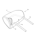
- FIG. 1 shows an example of a skin-integrated foam-molded product for explaining an embodiment of the present invention
- FIG. 2 shows a cross section of the skin-integrated foam-molded product of FIG.
- the headrest 10 includes a skin 11 constituting a headrest cover, a core body 12 filled in the skin 11, and an interior of the core body 12. And a metal frame 13 having a pair of legs exposed to the outside of the skin 11.
- the skin 11 is a single-layer structure of a surface material made of a fabric having liquid permeability such as a fabric, and is sewn in a bag shape.
- the skin 11 is turned upside down by a return opening 11a so that a seam allowance is on the inside. It is composed by binding.
- the core body 12 is made of a relatively soft foamed resin such as polyurethane foam, and is foamed inside the skin 11 and formed integrally with the skin 11.
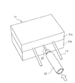
- FIG. 3 to 5 show an example of a method for manufacturing the headrest 10.
- the leg portion of the frame 13 is inserted into the through-hole 11b of the bag-shaped skin 11 to attach the frame 13 to the skin 11, and the foamed resin is inserted into the nozzle insertion port 11c of the skin 11
- the stock solution injection nozzle 20 is mounted.
- the skin 11 on which the frame 13 and the injection nozzle 20 are mounted is loaded into the cavity of the integral foam molding die 21 including the upper die 21a and the lower die 21b.
- the head portion of the injector 22 that supplies the foamed resin stock solution is connected to the injection nozzle 20, and the foamed resin stock solution is injected into the skin 11 through the injection nozzle 20.
- the core body 12 is molded by foaming a foamed resin stock solution inside.
- the skin 11, the core body 12, and the frame 13 are removed from the integral foam molding die 21, and the injection nozzle 20 is removed from the nozzle insertion port 11c to obtain the headrest 10.
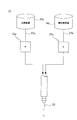
- FIG. 6 shows an exemplary configuration of the injector 22.
- description will be made assuming that foamed polyurethane is used as the foamed resin forming the core body 12.
- the foamed polyurethane is typically formed by mixing and foaming a main agent stock solution containing a polyol as a main component and a curing agent stock solution containing a polyisocyanate as a main component, and the injector 22 is a main agent stock solution storing the main agent stock solution.
- curing agent stock solution are provided.
- the main agent stock solution stored in the main agent stock solution tank 24a is supplied to the head portion of the injector 22 through the pipe 23a and the pump 25a, and the hardener stock solution stored in the hardener stock solution tank 24b is passed through the pipe 23b and the pump 25b.
- the main agent undiluted solution and the hardener undiluted solution supplied to the head portion of the injector 22 are discharged from the discharge port of the injection nozzle 20 connected to the head portion of the injector 22 at a predetermined blending ratio and a predetermined discharge pressure to form a bag shape. It is injected into the inside of the epidermis 11.
- the core 12 made of foamed polyurethane is formed.
- FIG. 7 shows an example of a mesh body that covers the discharge port of the injection nozzle 20
- FIG. 8 shows a state of a plurality of stock solutions of foamed resin when passing through the mesh body of FIG.
- the skin 11 has a single layer structure of a fabric having liquid permeability such as a fabric, and the stock solution from the injection nozzle 20 is used for the purpose of suppressing the penetration of the main agent stock solution and the curing agent stock solution into the skin 11.
- the discharge pressure is set low.
- the discharge pressure of the stock solution is usually 12 MPa to 18 MPa, whereas in this example where the skin 11 is a single layer structure of liquid permeable fabric.
- the discharge pressure of the stock solution is set to 8 MPa to 10 MPa, for example.
- pouring nozzle 20 is provided in the nozzle insertion port 11c of the outer skin 11 in order to compensate the mixing shortage of the main ingredient undiluted solution and hardening agent undiluted solution resulting from the fall of discharge pressure. Is provided.
- the mesh body 14 is obtained by sewing mesh fabric made of, for example, slab urethane into a bottomed cylindrical shape, and the edge of the opening end of the mesh body 14 is sewn or bonded to the nozzle insertion port 11c of the skin 11 so that the skin is covered. 11 is integrated.
- the injection nozzle 20 is inserted into the nozzle insertion port 11c of the skin 11 in a state where the protruding port at the tip of the injection nozzle 20 is in close contact with the bottom of the bottomed cylindrical mesh body 14, and the discharge port of the injection nozzle 20 is a mesh. Covered by body 14.
- the main agent stock solution and the curing agent stock solution discharged from the injection nozzle 20 are injected into the inside of the skin 11 through the mesh of the mesh body 14 that covers the discharge port, and collide and agitate when passing through the mesh of the mesh body 14. .
- mixing of the main agent stock solution and the curing agent stock solution is promoted, and even if the discharge pressure of the main agent stock solution and the curing agent stock solution is lowered, the foaming reaction is promoted, and the core body 12 can be stably molded.
- the discharge pressure of the main agent stock solution and the hardener stock solution the penetration of the main agent stock solution and the hardener stock solution into the skin 11 can be suppressed, and the texture of the skin 11 can be prevented from being damaged.
- the mesh-shaped dough forming the mesh body 14 preferably has an air permeability that allows the main agent stock solution and the curing agent stock solution to pass without stagnation, depending on the viscosity of the main agent stock solution and the curing agent stock solution, It preferably has an air permeability of 100 cm 3 / cm 2 / s or more.
- the air permeability is a value measured by the air permeability test method defined in JIS L 1096, and the contents of JIS L 1096 are incorporated herein by reference.
- the mesh-shaped fabric forming the mesh body 14 is 1000 cm. It preferably has an air permeability of 3 / cm 2 / s or less.
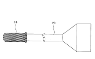
- FIG. 9 shows a modification of the mesh body 14 shown in FIG.
- the mesh body 14 is configured as a cap that is fixed to the tip of the injection nozzle 20. That is, a mesh body 14 in which a mesh fabric is sewn into a bottomed cylinder is prepared separately from the skin 11, the mesh body 14 is fixed to the tip of the injection nozzle 20, and the discharge port of the injection nozzle 20 is formed by the mesh body 14. In this state, the injection nozzle 20 may be inserted into the nozzle insertion port 11 c of the skin 11.
- the main agent stock solution and the curing agent stock solution discharged from the injection nozzle 20 are injected into the inside of the skin 11 through the mesh of the mesh body 14 covering the discharge port, and collide when passing through the mesh of the mesh body 14. Together, the mixture is stirred to promote mixing of the main agent stock solution and the curing agent stock solution.
- the skin 11 has been described as having a single layer structure of a cloth (surface material) having liquid permeability, but the present invention is also applicable when the skin has a two-layer structure of a surface material and a wadding.
- the core body 12 can be stably molded by promoting the mixing of a plurality of stock solutions of foamed resin forming the core body 12, and the penetration of the stock solution into the epidermis is suppressed to prevent the skin texture from being damaged. be able to.
- the present invention can also be applied to other skin-integrated foamed molded products such as armrests and seat trays.
Landscapes
- Engineering & Computer Science (AREA)
- Aviation & Aerospace Engineering (AREA)
- Transportation (AREA)
- Mechanical Engineering (AREA)
- Manufacturing & Machinery (AREA)
- Casting Or Compression Moulding Of Plastics Or The Like (AREA)
- Chair Legs, Seat Parts, And Backrests (AREA)
- Seats For Vehicles (AREA)
- Molding Of Porous Articles (AREA)
Abstract
Description
11 表皮
12 芯体
13 フレーム
14 メッシュ体
20 注入ノズル
21 一体発泡成形用金型
22 注入器
24a 主剤原液タンク
24b 硬化剤原液タンク
Claims (6)
- 発泡樹脂の複数の原液を袋状の表皮内部に注入し、発泡樹脂からなる芯体を表皮と一体に成形してなる表皮一体発泡成形品の製造方法であって、
前記複数の原液を前記表皮内部に注入するノズルの吐出口をメッシュ体で蓋し、前記複数の原液を前記メッシュ体を通して前記表皮内部に注入する表皮一体発泡成形品の製造方法。 - 請求項1記載の表皮一体発泡成形品の製造方法であって、
前記メッシュ体は、前記表皮と一体に前記表皮内部へのノズル挿し込み口に有底筒状に設けられ、前記ノズルの先端部を収容するカバーとして構成される表皮一体発泡成形品の製造方法。 - 請求項1記載の表皮一体発泡成形品の製造方法であって、
前記メッシュ体は、前記ノズルの先端部に固定されるキャップとして構成される表皮一体発泡成形品の製造方法。 - 請求項1から3のいずれか一項記載の表皮一体発泡成形品の製造方法であって、
前記メッシュ体は、通気度100cm3/cm2/s以上1000cm3/cm2/s以下である表皮一体発泡成形品の製造方法。 - 請求項1から4のいずれか一項記載の表皮一体発泡成形品の製造方法であって、
前記複数の原液の吐出圧は、8MPa以上10MPa以下である表皮一体発泡成形品の製造方法。 - 請求項1から5のいずれか一項記載の表皮一体発泡成形品の製造方法であって、
前記表皮は、液浸透性を有する生地の一層構造である表皮一体発泡成形品の製造方法。
Priority Applications (3)
| Application Number | Priority Date | Filing Date | Title |
|---|---|---|---|
| MX2017015348A MX2017015348A (es) | 2015-05-29 | 2016-05-20 | Metodo para producir articulo moldeado espumado con cubierta de superficie integrada. |
| CN201680031490.9A CN107949465B (zh) | 2015-05-29 | 2016-05-20 | 表皮一体发泡成形品的制造方法 |
| US15/577,985 US20180290350A1 (en) | 2015-05-29 | 2016-05-20 | Method for producing foamed molded article with integrated surface skin |
Applications Claiming Priority (2)
| Application Number | Priority Date | Filing Date | Title |
|---|---|---|---|
| JP2015109811A JP6431812B2 (ja) | 2015-05-29 | 2015-05-29 | 表皮一体発泡成形品の製造方法 |
| JP2015-109811 | 2015-05-29 |
Publications (1)
| Publication Number | Publication Date |
|---|---|
| WO2016194663A1 true WO2016194663A1 (ja) | 2016-12-08 |
Family
ID=57441529
Family Applications (1)
| Application Number | Title | Priority Date | Filing Date |
|---|---|---|---|
| PCT/JP2016/065067 Ceased WO2016194663A1 (ja) | 2015-05-29 | 2016-05-20 | 表皮一体発泡成形品の製造方法 |
Country Status (5)
| Country | Link |
|---|---|
| US (1) | US20180290350A1 (ja) |
| JP (1) | JP6431812B2 (ja) |
| CN (1) | CN107949465B (ja) |
| MX (1) | MX2017015348A (ja) |
| WO (1) | WO2016194663A1 (ja) |
Families Citing this family (7)
| Publication number | Priority date | Publication date | Assignee | Title |
|---|---|---|---|---|
| WO2017141972A1 (ja) * | 2016-02-17 | 2017-08-24 | 株式会社イノアックコーポレーション | 表皮一体発泡品及びその製造方法 |
| JP6796001B2 (ja) * | 2017-02-27 | 2020-12-02 | 株式会社タチエス | 車両用シートのヘッドレスト |
| JP7365106B2 (ja) * | 2018-03-22 | 2023-10-19 | 株式会社タチエス | 表皮一体発泡成型品の製造方法 |
| CN108995238A (zh) * | 2018-06-29 | 2018-12-14 | 张哲恺 | 一种Polymorph树脂制品及其制备方法 |
| CA3106714A1 (en) * | 2018-07-23 | 2020-01-30 | Proprietect L.P. | Automotive trim device |
| JP7439649B2 (ja) * | 2020-06-01 | 2024-02-28 | トヨタ紡織株式会社 | 乗物用ヘッドレスト |
| JP7764010B2 (ja) | 2021-07-16 | 2025-11-05 | デルタ工業株式会社 | ヘッドレストの製造方法 |
Citations (2)
| Publication number | Priority date | Publication date | Assignee | Title |
|---|---|---|---|---|
| JPS499063B1 (ja) * | 1970-08-03 | 1974-03-01 | ||
| JP2015002762A (ja) * | 2013-06-19 | 2015-01-08 | 株式会社タチエス | 車両用の表皮一体発泡品とその製造方法 |
Family Cites Families (9)
| Publication number | Priority date | Publication date | Assignee | Title |
|---|---|---|---|---|
| JPS523500B2 (ja) * | 1972-05-23 | 1977-01-28 | ||
| DE3440976A1 (de) * | 1984-11-09 | 1986-05-15 | Gebr. Happich Gmbh, 5600 Wuppertal | Sonnenblende fuer fahrzeuge |
| JP3698932B2 (ja) * | 1999-10-12 | 2005-09-21 | 難波プレス工業株式会社 | 充填体 |
| TWI363072B (en) * | 2004-05-28 | 2012-05-01 | Sulzer Chemtech Ag | A method for the manufacture of a foamed polymer body |
| WO2006001067A1 (ja) * | 2004-06-29 | 2006-01-05 | Inoac Corporation | 発泡成形体用縫製糸、発泡成形体及び発泡成形体の製造方法 |
| US9333690B2 (en) * | 2010-03-26 | 2016-05-10 | Mitsubishi Heavy Industries Plastic Technology | Method for manufacturing a fiber-reinforced composite material |
| MY152024A (en) * | 2010-07-13 | 2014-08-15 | Mitsui Chemicals Inc | Multilayer nonwoven fabric for foam molding |
| JP6157946B2 (ja) * | 2013-06-19 | 2017-07-05 | 株式会社タチエス | ヘッドレストの一体発泡成形用金型およびヘッドレストの一体発泡成形品の製造方法 |
| EP3144119B1 (en) * | 2014-05-11 | 2024-09-04 | Yasuhiro Suzuki | Method for manufacturing molded article |
-
2015
- 2015-05-29 JP JP2015109811A patent/JP6431812B2/ja active Active
-
2016
- 2016-05-20 CN CN201680031490.9A patent/CN107949465B/zh not_active Expired - Fee Related
- 2016-05-20 WO PCT/JP2016/065067 patent/WO2016194663A1/ja not_active Ceased
- 2016-05-20 US US15/577,985 patent/US20180290350A1/en not_active Abandoned
- 2016-05-20 MX MX2017015348A patent/MX2017015348A/es unknown
Patent Citations (2)
| Publication number | Priority date | Publication date | Assignee | Title |
|---|---|---|---|---|
| JPS499063B1 (ja) * | 1970-08-03 | 1974-03-01 | ||
| JP2015002762A (ja) * | 2013-06-19 | 2015-01-08 | 株式会社タチエス | 車両用の表皮一体発泡品とその製造方法 |
Also Published As
| Publication number | Publication date |
|---|---|
| MX2017015348A (es) | 2018-07-06 |
| CN107949465B (zh) | 2020-02-11 |
| JP2016221810A (ja) | 2016-12-28 |
| US20180290350A1 (en) | 2018-10-11 |
| JP6431812B2 (ja) | 2018-11-28 |
| CN107949465A (zh) | 2018-04-20 |
Similar Documents
| Publication | Publication Date | Title |
|---|---|---|
| JP6431812B2 (ja) | 表皮一体発泡成形品の製造方法 | |
| JP2009286054A (ja) | 金型及び樹脂発泡成形品の成形方法 | |
| JP2017206077A (ja) | 車両用シートパッド及びその製造方法 | |
| WO2016194664A1 (ja) | 表皮一体発泡成形品の製造方法 | |
| JP5421621B2 (ja) | トリムカバー | |
| JP2007195768A (ja) | フレーム付表皮一体発泡品 | |
| KR200458213Y1 (ko) | 파운데이션 충진장치용 확산기 및 이를 갖는 충전장치 | |
| TW200609281A (en) | A method for the manufacture of a foamed polymer body | |
| JP6807104B2 (ja) | 発泡樹脂の製造装置 | |
| WO2014087953A1 (ja) | 表皮一体発泡成形品の製造方法 | |
| JP4067626B2 (ja) | エアゾール製品およびその製法 | |
| JP6660833B2 (ja) | 表皮一体発泡成形品 | |
| KR100204817B1 (ko) | 발포성 재료의 발포성형방법 및 발포장치 | |
| JP4137090B2 (ja) | 表皮一体発泡品の製造装置 | |
| CN116766480A (zh) | 一种车用头枕的灌泡工艺 | |
| US20250269776A1 (en) | Padding element for a vehicle seat | |
| JP6234238B2 (ja) | 袋状表皮一体発泡成形品及びその製造方法 | |
| JP2016107891A (ja) | 防舷材および防舷材の製造方法 | |
| JP4498960B2 (ja) | 表皮一体発泡品の製造装置 | |
| JP6008368B2 (ja) | 表皮一体発泡成形品及びその製造方法 | |
| WO1997002127A1 (en) | Method and apparatus for foaming | |
| KR100486387B1 (ko) | 발포성 재료의 발포장치 | |
| JP4209893B2 (ja) | アームレスト製造装置 | |
| JP2007083863A (ja) | カップホルダー付表皮一体発泡品の製造方法 | |
| JP6404429B2 (ja) | 袋状表皮一体発泡成形品及びその製造方法 |
Legal Events
| Date | Code | Title | Description |
|---|---|---|---|
| 121 | Ep: the epo has been informed by wipo that ep was designated in this application |
Ref document number: 16803098 Country of ref document: EP Kind code of ref document: A1 |
|
| WWE | Wipo information: entry into national phase |
Ref document number: 15577985 Country of ref document: US Ref document number: MX/A/2017/015348 Country of ref document: MX |
|
| NENP | Non-entry into the national phase |
Ref country code: DE |
|
| 122 | Ep: pct application non-entry in european phase |
Ref document number: 16803098 Country of ref document: EP Kind code of ref document: A1 |