WO2016190153A1 - 車載用電子機器のカバー - Google Patents
車載用電子機器のカバー Download PDFInfo
- Publication number
- WO2016190153A1 WO2016190153A1 PCT/JP2016/064480 JP2016064480W WO2016190153A1 WO 2016190153 A1 WO2016190153 A1 WO 2016190153A1 JP 2016064480 W JP2016064480 W JP 2016064480W WO 2016190153 A1 WO2016190153 A1 WO 2016190153A1
- Authority
- WO
- WIPO (PCT)
- Prior art keywords
- cover
- engaged
- engaging
- window glass
- base member
- Prior art date
- Legal status (The legal status is an assumption and is not a legal conclusion. Google has not performed a legal analysis and makes no representation as to the accuracy of the status listed.)
- Ceased
Links
Images










Classifications
-
- B—PERFORMING OPERATIONS; TRANSPORTING
- B60—VEHICLES IN GENERAL
- B60R—VEHICLES, VEHICLE FITTINGS, OR VEHICLE PARTS, NOT OTHERWISE PROVIDED FOR
- B60R11/00—Arrangements for holding or mounting articles, not otherwise provided for
- B60R11/04—Mounting of cameras operative during drive; Arrangement of controls thereof relative to the vehicle
-
- B—PERFORMING OPERATIONS; TRANSPORTING
- B60—VEHICLES IN GENERAL
- B60R—VEHICLES, VEHICLE FITTINGS, OR VEHICLE PARTS, NOT OTHERWISE PROVIDED FOR
- B60R11/00—Arrangements for holding or mounting articles, not otherwise provided for
- B60R11/02—Arrangements for holding or mounting articles, not otherwise provided for for radio sets, television sets, telephones, or the like; Arrangement of controls thereof
-
- B—PERFORMING OPERATIONS; TRANSPORTING
- B60—VEHICLES IN GENERAL
- B60R—VEHICLES, VEHICLE FITTINGS, OR VEHICLE PARTS, NOT OTHERWISE PROVIDED FOR
- B60R11/00—Arrangements for holding or mounting articles, not otherwise provided for
- B60R2011/0001—Arrangements for holding or mounting articles, not otherwise provided for characterised by position
- B60R2011/0003—Arrangements for holding or mounting articles, not otherwise provided for characterised by position inside the vehicle
- B60R2011/0026—Windows, e.g. windscreen
-
- B—PERFORMING OPERATIONS; TRANSPORTING
- B60—VEHICLES IN GENERAL
- B60R—VEHICLES, VEHICLE FITTINGS, OR VEHICLE PARTS, NOT OTHERWISE PROVIDED FOR
- B60R11/00—Arrangements for holding or mounting articles, not otherwise provided for
- B60R2011/0042—Arrangements for holding or mounting articles, not otherwise provided for characterised by mounting means
- B60R2011/0049—Arrangements for holding or mounting articles, not otherwise provided for characterised by mounting means for non integrated articles
- B60R2011/005—Connection with the vehicle part
- B60R2011/0059—Connection with the vehicle part using clips, clamps, straps or the like
-
- B—PERFORMING OPERATIONS; TRANSPORTING
- B60—VEHICLES IN GENERAL
- B60R—VEHICLES, VEHICLE FITTINGS, OR VEHICLE PARTS, NOT OTHERWISE PROVIDED FOR
- B60R11/00—Arrangements for holding or mounting articles, not otherwise provided for
- B60R2011/0042—Arrangements for holding or mounting articles, not otherwise provided for characterised by mounting means
- B60R2011/0049—Arrangements for holding or mounting articles, not otherwise provided for characterised by mounting means for non integrated articles
- B60R2011/0064—Connection with the article
- B60R2011/0075—Connection with the article using a containment or docking space
-
- B—PERFORMING OPERATIONS; TRANSPORTING
- B60—VEHICLES IN GENERAL
- B60Y—INDEXING SCHEME RELATING TO ASPECTS CROSS-CUTTING VEHICLE TECHNOLOGY
- B60Y2410/00—Constructional features of vehicle sub-units
- B60Y2410/113—Mount clips, snap-fit, e.g. quick fit with elastic members
Definitions
- the present invention relates to a cover for an in-vehicle electronic device mounted in a vehicle interior, and more particularly to a camera fixedly engaged with a base member fixed to a window glass (including a front glass, a side glass, a rear glass, etc., hereinafter the same). It is related with the cover which covers electronic devices, such as.
- FIGS. 18A and 18B show a camera cover disclosed in Patent Document 1
- FIG. 19 shows a camera cover disclosed in Patent Document 2.
- the camera cover 1 includes a camera storage unit 2 that stores the camera and a harness storage unit 3 that stores a wire harness connected to the camera.
- the camera storage unit 2 slides in the imaging direction of the camera. It is characterized in that it has an engaging portion 2aa that is engaged with a pin P that is an engaged portion on the windshield FG side while being moved.
- the harness storage section 3 has the same length X as the distance between the camera storage section 2 and the vehicle ceiling RH, and the wire harness on the opposite side to the imaging direction of the camera storage section 2.
- 2b has a slide groove extending in the vertical direction to the glass and a hole formed in the vertical direction, and the harness storage part 2 is slidably fitted into the slide groove. And a convex portion that can be fitted into the hole.
- the camera cover 1 is less rigid than the storage portion 2 a for storing the camera, wall surface portions located on both sides of the storage portion 2 a in the vehicle width direction, and the main body portion 2 including the storage portion 2 a and the wall surface portion. It is characterized by having an elastic part 3 made of a material and projecting rearward from the main body part 2 and abutting against a ceiling part R in the vehicle. Furthermore, in FIG. 19, it has the pin P which protrudes toward the wall surface part from several bracket BK which is joined to the windshield FG and protrudes toward the vehicle interior, and is located inside the vehicle width direction of the wall surface part.
- the wall surface portion is characterized in that it has a guide 2c shaped so as to be fitted to the pin P by sliding along the windshield FG from the rear to the front of the vehicle.
- the mutual engaging means is a plurality of pins P provided on a bracket BK whose engaging portion is fixed to the windshield FG, and the engaged portion is an inner wall of the camera cover 1 (the camera storage portion 2 in Reference 1). It is a substantially U-shaped guide 2aa or 2c that is fitted in or engages with the corresponding pin P by sliding from the rear to the front of the vehicle.
- the cover-side U-shaped guide is positioned on the corresponding pin of the bracket on the fixed side, and from this state, the cover is attached to the vehicle. Since the pin has to be slid from the rear to the front and inserted into the U shape of the guide and engaged, mounting operability is lacking. Also, when removing the camera cover (camera housing part in Document 1), the cover must be slid from the front to the back by the length of the U-shaped guide, and because of sliding, it hits the ceiling part. In such a case, the harness housing part must be removed in advance, and in the case of Document 2, the cover must be slid strongly and the rear end side must be elastically displaced. Further, in each engagement structure, since the pin is only inserted into the U shape of the guide, there is a possibility that the cover may slightly move or a rubbing noise may be generated in the engagement portion when vibration is applied.
- An object of the present invention is to provide a cover structure that is easy to attach and remove, and that can maintain a stable engagement state even when vibrations are applied, and that does not cause the generation of rubbing noise on the engagement portion.
- Other purposes will be clarified in the description below.
- the base member (1, 4, 6) fixed to the window glass of the vehicle is engaged and fixed by mutual engaging means that can be engaged with each other, and is held by the installation portion such as the window glass or the base member.
- the present invention as described above is more preferably embodied as specified in the following (2) to (8).
- the urging means is provided on either the base member or the cover.
- the urging means is provided in any one of the engaging portion and the engaged portion.
- the biasing means has an elastic piece that can be bent and deformed, and the engagement between the engaging portion and the engaged portion moves the cover against the biasing direction of the elastic piece. It is a configuration that can be released with.
- the engaging portion (15) is provided on a pair of sandwiching pieces (16, 17) forming a receiving space (18) therebetween and the one sandwiching piece. It has a retaining claw (17a) protruding into the receiving space, and the engaged portion (35) is an engaging projection (39a) that can be engaged with the retaining claw, and the elastic piece (38).
- the engaged portion enters the receiving space with displacement in the biasing direction of the elastic piece, and the engaging protrusion is It is a structure that can be engaged with the retaining claw.
- the engaging portion (45) is provided on one of the pair of sandwiching pieces (47, 48) forming a receiving space (46) therebetween and one of the sandwiching pieces.
- the holding claw (47a) protrudes into the receiving space, and the other of the clamping pieces is formed as the elastic piece (48), and the engaged portion (55)
- It has an engagement step (55a) that can be engaged with a stop claw, and when the cover is pushed toward the vehicle window glass, the engaged portion is displaced in the biasing direction of the elastic piece. And the engagement step can be engaged with the retaining claw.
- the engaging portion (65) has a recess (67) opened toward the upper side of the window glass and the elastic piece (68), and
- the joint portion (75) has an engaging projection (75a) that engages with the recess and a contact portion (76) that contacts the elastic piece, and when the cover is pushed toward the vehicle window glass.
- the engaging projection can be engaged with the recess with displacement of the elastic piece in the biasing direction via the abutting portion.
- the cover is predetermined with respect to the base member as illustrated in FIG. 7, FIG. 12, and FIG.
- the joint portions are brought into a state where they can be engaged with each other with displacement in a direction in which the biasing force is accumulated in the biasing means.
- the cover is moved to the position where the engaging portion and the engaged portion are engaged by the urging force of the urging means as shown in FIGS. 7, 12, and 16 (b). It is slid and held in a biased state.
- the urging means has an elastic piece that can be bent and deformed, and the engagement between the engaging portion and the engaged portion is shown in each of FIGS. 8, 13, and 17 (a). As illustrated, the cover can be released by moving against the urging direction of the elastic piece, so that the engagement releasing operation when removing the cover is also facilitated.
- the invention of (5) has, for example, a pair of clamping pieces (16, 17) provided on the base member (1) and a retaining claw (17a).
- the engaged portion (35) is provided on the cover (3) and has an elastic piece (38) together with the engaging projection (39a).
- the engaging portion (45) is elastic with the pair of clamping pieces (47, 48) and the retaining claws (47a) provided on the base member (4). It has a piece (48), the engaged part (55) has an engagement step (55a) provided in the cover (5), and when the cover is pushed toward the vehicle window glass, Since the part enters the receiving space (46) with the displacement of the elastic piece in the biasing direction, and the engagement step can be engaged with the claw, it can be implemented with a simple configuration in this case as well as with the mounting operability. The stability retention can be improved, and the disengagement operation becomes easy.
- the engaging portion (65) has the recess (67) and the elastic piece (68) provided in the base member (6), and the engaged portion (75) is the cover. It has the engaging projection (75a) and the abutting portion (76) provided in (7), and when the cover is pushed toward the vehicle window glass, the elastic piece is biased through the abutting portion. Since the engaging projection can be engaged with the recess with this displacement, it can be implemented with a simple configuration in this case as well, and the stability and holding performance can be improved together with the mounting operability, and the engagement releasing operation is facilitated.
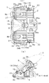
- FIG. 4A is a top view of the base member
- FIG. 4B is a side view of the base member viewed from the lower side of FIG. 5A
- FIG. 5C is a cross-sectional view taken along line AA of FIG. .
- the single holder fixed to the base member is shown, (a) is a top view, (b) is a side view as viewed from the lower side of the paper of (a), and (c) is along the line BB of (a).
- FIG. 5A is an enlarged view of the E portion of FIG. 5B
- FIG. 5B is a state diagram in which the engaged portion enters the receiving space of the engaging portion with the displacement of the elastic piece
- FIG. 5C is the engaged portion. It is the state figure which the part engaged with the engaging part.
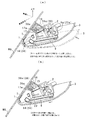
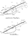
- the operation for engaging and fixing the cover to the base member is shown, (a) is a schematic view showing a process of pushing the cover toward the window glass, and (b) is a schematic view showing a state where the cover is engaged and fixed to the base member. It is.
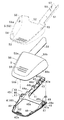
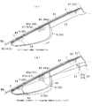
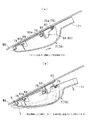
- the operation of removing the cover from the base member is shown, (a) is a schematic view showing the process of sliding the cover backward against the urging force and releasing the engagement, and (b) is a diagram showing the process of rotating the cover to the indoor side or It is a schematic diagram which shows the process of pulling and removing. It is a disassembled perspective view of the cover and base member which show the 2nd form of this invention.
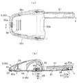
- the top view seen from the top in the state which engaged and fixed the said cover to the base member is sectional drawing along the FF line of (a).
- the base member is shown together with a cover
- (a) is a schematic top view
- (b) is a relational diagram showing the base member as a side surface and the cover as a cross section taken along line GG in (a).
- the operation for engaging and fixing the cover to the base member is shown, (a) is a schematic view showing a process of pushing the cover toward the window glass, and (b) is a schematic view showing a state where the cover is engaged and fixed to the base member. It is.
- the operation of removing the cover from the base member is shown, (a) is a schematic view showing the process of sliding the cover backward against the urging force and releasing the engagement, and (b) is a diagram showing the process of rotating the cover to the indoor side or It is a schematic diagram which shows the process of pulling and removing. It is a disassembled perspective view of the cover and base member which show the 3rd form of this invention. It is a schematic diagram which shows the relationship of the said base member and cover with respect to a window glass.
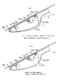
- the operation for engaging and fixing the cover to the base member is shown, (a) is a schematic view showing a process of pushing the cover toward the window glass, and (b) is a schematic view showing a state where the cover is engaged and fixed to the base member.
- the object of the invention of each embodiment is an in-vehicle electronic device that covers and fixes an electronic device that is engaged and fixed to base members 1, 4, and 6 fixed to a window glass WG of a vehicle and held in an installation portion such as a window glass or a base member Equipment covers 3, 5 and 7.
- the first form is a holder 2 connected to the base member 1
- the second form and the third form are examples in which a part of the window glass WG is assumed.
- the base members 1, 4, 6 and the covers 3, 5, 7, and the holder 2 are all resin molded products, but they may be other than resin.
- the cover 3 is engaged and fixed to the base member 1 by mutual engaging means that can be engaged with each other.
- the mutual engaging means includes an engaging portion 15 provided on one of the base member 1 and the cover 3, an engaged portion 35 provided on the other and engaged with the engaging portion 15, the engaging portion 15 and the covered portion.
- the elastic piece 38 is an urging means that is provided in any of the engaging portions 35 and urges the engaged portion 35 to engage with the engaging portion 15. Then, when the cover 3 is pushed toward the vehicle window glass WG, the engaged portion 35 is engaged with the engaging portion 15 in a state of being urged by the elastic piece 38 in the direction along the window glass surface. This engagement can be released by moving the cover 3 against the urging direction of the elastic piece 38.
- the base member 1 has a rectangular shape that is long in the vehicle width direction as shown in FIGS.
- the base member 1 has mounting surfaces 1a and 1a for the window glass WG provided on the left and right sides on the outer surface side, and a hollow portion 1b provided between the left and right middle portions, that is, between the mounting portions 1a and partitioned by the reverse concave portion 10;
- Through holes 11, 11 provided on the left and right sides of the outer front side and penetrating from the inside to the outside, stepped locking receiving portions 13, 13 provided in the middle of the left and right sides of the outer front side, and both locking receiving portions 13
- Cover positioning projections 13a provided between them
- holder positioning projections 12 and 12 provided on both sides of the inner rear side and the rear side of the reverse concave portion 10 which are narrowed, and both side surfaces in the width direction Are provided with an engaging hole 14, a restricting portion 14a, an engaging portion 15, a positioning portion 19 for the cover, and the like.
- each mounting surface 1a is formed flat, and is fixed to a predetermined position of the window glass WG as an installation portion with a double-sided adhesive tape T or an adhesive as shown in FIG. 4B.
- the hollow portion 1b is formed wider on the front side than the rear side, and the sensor module 9 is held in a state where the sensor module 9 is held as an electronic device in the holder 2 connected to the base member 1 as shown in FIG.
- the camera 8 which comprises can image and monitor the front from the hollow part 1b through the window glass WG.
- the sensor module 9 is one of the sensors for assisting safe driving like the front monitoring camera.
- the camera 8, FPGA (field-programmable gate array), CPU, memory and the like are mounted on the substrate.
- the sensor module 9 includes protrusions 9a and 9a protruding from both side surfaces and protrusions 9b and 9b protruding from the front edge as an attachment structure.
- the target electronic device may be any device that can be monitored forward, and may be a camera, a radio wave radar, or a similar configuration.
- the engaging portion 15 includes a pair of holding pieces 16 and 17 that form a receiving space 18 therebetween, and a retaining claw 17 a that is provided at the tip of one holding piece 17 and protrudes into the receiving space 18.
- Reference numeral 15 a denotes a convex portion that receives the corresponding piece portion 37 that protrudes from the inner bottom surface of the receiving space 18 and forms the engaged portion 35.
- Reference numeral 15b denotes a guide piece for facilitating insertion of the engaged portion 35 into the receiving space 18, and is formed on an invitation inclined surface that becomes lower as the upper end side goes upward.
- the positioning portion 19 has a flat and wide end surface disposed on the inner surface of the cover 3.
- the holder 2 has a substantially rectangular plate shape as shown in FIG. 3 and FIG. 4, and is provided at the front left and right intermediate portions, and has a notch portion 20 that receives the reverse concave portion 10, and front left and right ends that define the notch portion 20.
- the insertion portions 21 and 21 that are projected and inserted into the corresponding through holes 11, the standing walls 22 and 22 that are provided on both sides and gradually lower from the rear side toward the front side, and the standing walls that are juxtaposed on the standing walls 22.
- the elastic locking piece which erected on the inner bottom surface of the vertical hole and defines the engagement space 25 between the rear end surface of the vertical wall 22 and the standing wall 23 which defines the vertical hole with the rear end surface of the vertical wall 22 26 and a pair of claws 24a, 24b protruding from the outer surface of each standing wall 22.
- Each insertion part 21 is formed in a substantially inverted L-shaped longitudinal section as shown in FIGS. 3 and 4, and has an inner space 21a and an opening 21b communicating with the upper and lower sides.
- a retaining claw 22 a that protrudes into the engagement space 25 from the upper side is provided.
- the elastic locking piece 26 has a guide surface 26a that is provided at the upper end and is located on the outer side of the engagement space 25 from the bottom to the top.
- the holding portion on which the sensor module 9 is placed includes pieces 27 and 28a that allow the bottom surface of the sensor module 9 to be elastically held, a locking piece 28 that presses and locks the rear surface of the sensor module 9, and a sensor A recess 29 for receiving the camera 8 of the module 9 is provided.
- the insertion portions 21 are fitted into the corresponding through holes 11 with respect to the base member 1, and the claws 24 a and 24 b are engaged with the corresponding engagement holes 14 and the restriction portions 14 a.
- a cushioning material such as felt (not shown) is interposed at a place where the holder 2 and the base member 1 overlap.
- the sensor module 9 is engaged with the protrusions 9a on both sides of the holder 2 in the corresponding engagement spaces 25 and the protrusions 9b on the front edge are engaged with the corresponding inner spaces 21a. It is connected and held by being elastically locked by.
- the holder 2 is set to an optimum shape according to the target electronic device.
- the holder 2 can be omitted when the electronic device is configured to be fixed to the window glass WG with a double-sided adhesive tape or the like.
- the cover 3 is a storage portion in which the base member 1 and the holder 2 in which the outer surface 30 is a design surface and the inner portion 31 is connected to each other can be arranged.
- the rear end 3b is a side away from the window glass WG, and is formed with a width dimension slightly smaller than that of the front end 3a.
- the cover 3 protrudes from the inner surface in the middle of the left and right of the front end 3 a and engages with the engagement receiving portions 13, 13.
- the cover 3 is provided between the engagement pieces 33.
- An engaged portion 35 that is releasably engaged with the portion 15 is provided.
- Reference numeral 32 denotes a plurality of lateral grooves provided in the main portion of the cover 3.
- Each locking piece 33 has a flat inner surface formed in a state of protruding from the rising inner surface of the cover front end 3a.
- the cover 3 rotates toward the window glass WG around the locking piece 33 in a state where each locking piece 33 is in contact with or engaged with the step of the corresponding locking receiving portion 13 with respect to the base member 1.
- the abutting wall 34 hits the positioning portion 19 and slides on the positioning portion, and the engaged portion 35 enters the receiving space 18 of the engaging portion 15 and is engaged.
- Each engaged portion 35 protrudes from the rising inner surface of the cover side end 3c and faces the width direction.
- Each engaged portion 35 has a substantially rectangular cylindrical shape, and has opposed pieces 36 and 37 and another opposed pieces 38 and 39.
- the piece 39 has an engagement projection 39a that can be engaged with the claw 17a by projecting a portion located between the piece 37 and the engagement projection 39a, that is, on the side opposite to the engagement projection 39a.
- a restricting piece 39b projecting from the head.
- a part 37 and a part of the engaging protrusion 39a are provided with a flange portion 37a protruding outward from the tip.
- the flange portion 37a hits the tip inclined surface of the guide piece 15b on the receiving space side, and from there along the piece 15b, It is slid to the inner bottom surface. In this state, a part of the piece portion 37 is in contact with the convex portion 15a.
- the piece portion 38 is formed as an elastic piece which is separated from the piece portions 37 and 36 by vertical slits S on both sides and can be flexibly deformed. In the following description, this piece is referred to as an elastic piece 38.
- the elastic piece 38 has a flange portion 38a that protrudes outward from the tip, and is oscillated and displaced into a cylindrical shape via the flange portion 38a. In this case, the elastic piece 38 is in an initial position where the urging force is not expressed as shown in FIG. 6A when the engaged portion 35 is in a stage before entering the receiving space 18.
- the engaging protrusion 39a hits the claw 17a in the process of entering the space 18, it is elastically displaced into the cylinder until it hits the restricting piece 39b by the reaction force received from the clamping piece 16 when getting over the claw 17a. As shown in b), the maximum urging force is accumulated.
- the engaged portion 35 moves in a direction in which the engaging protrusion 39a and the claw 17a are engaged by the urging force accumulated in the elastic piece 38 after the engaging protrusion 39a gets over the claw 17a as shown in FIG. 6C. Moved a little.
- the elastic piece 38 urges the engaged portion 35 in a direction to maintain the engaged state.
- FIG. 7 shows, for example, a case in which the holder 2 is engaged and connected to the base member 1 and the sensor module 9 is held by the holder 2 on both sides of a predetermined installation portion of the vehicle window glass WG.
- An operation example in the case where the cover 3 is engaged and fixed to the base member 1 from the attached state after being fixed by the adhesive tape T or the like is shown.
- FIG. 8 shows an operation example when the cover 3 is removed again for maintenance or the like.
- the main operation when the cover 3 is engaged and fixed to the base member 1 is as follows.
- the cover 3 is arranged at a predetermined position with respect to the base member 1 as shown by the one-dot chain line in FIG.
- the locking piece 33 on the cover side is engaged with the locking receiving portion 13 on the base member side.
- the cover 3 is rotated or pushed toward the window glass WG in this positioning state. That is, when the cover 3 is pressed by hand or the like toward the window glass WG in the arrow direction of FIG. 7A, the elastic piece 38 accumulates the urging force as shown in FIG. 6B as described above.
- the claw 17a and the engagement protrusion 39a are brought into a state where they can be engaged with each other with the displacement in the direction. Thereafter, when the pressing hand is released, the cover 3 is slightly in the direction of the arrow in FIG. 7B with a part of the urging force accumulated in the elastic piece 38 as shown in FIGS. 7B and 6C.
- the engagement protrusion 39a is engaged with the claw 17a by being moved by the amount, and the engagement state is held in a state of being urged by the elastic piece 38.
- the operation of engaging and fixing the cover 3 to the base member 1 is a simple operation of pushing toward the window glass WG, and the cover is moved along the window glass surface as in References 1 and 2.
- One-touch operation can be realized compared to the sliding configuration.
- the cover 3 is engaged with a part of the urging force accumulated in the elastic piece 38 in the receiving space 18 as shown in FIG. 6C when the cover 3 is engaged and fixed to the base member 1. It is urged in a direction that maintains the combined state, that is, in a direction that makes it difficult to disengage. For this reason, in this structure, even if an inadvertent external force is applied to the engagement fixing portion, the engagement is not easily released, and the stability and stability can be improved as well as the mounting operability.
- This embodiment is different from the first embodiment in that an electronic device such as a camera (not shown) is fixed to the window glass WG by a double-sided adhesive tape, and the base member 4 and the cover 5 are the electronic device. It is different in that it is held and covered including the wire harness connected to. That is, in FIG. 9 to FIG. 13, the base member 4 includes a substantially rectangular frame-shaped main body portion 40 that allows the electronic device fixed to the window glass WG to escape, and a harness holding portion 41 that holds the wire harness.
- the cover 5 includes a main portion 50 that covers the main body portion 40 and an extension portion 51 that covers the harness holding portion 41.
- the main part 50 is engaged and fixed to the main body part 40 by mutual engagement means that can be engaged with each other.
- the mutual engagement means includes an engagement portion 45 provided on one of the main body portion 40 and the main portion 50, an engaged portion 55 provided on the other side and engaged with the engagement portion 45, an engagement portion 45, and It comprises an elastic piece 48 which is provided in any of the engaged portions 55 and is an urging means for urging the engaged portion 55 in a direction to engage with the engaging portion 45.
- the extension portion 51 is engaged and fixed to the harness holding portion 41 by mutual engagement means that can be engaged with each other.
- the mutual engagement means includes a swing piece 43 that is an engagement portion provided on one of the harness holding portion 41 and the extension portion 51 and a protrusion 57 that is provided on the other side and engages with the swing piece 43. Then, when the cover 5 is pushed toward the vehicle window glass WG, the engaged portion 55 is engaged with the engagement portion 45 in a state of being urged by the elastic piece 38 in the direction along the window glass surface, and at the same time, the protrusion 57 is engaged with the corresponding swinging piece 43. These engagements can be released by moving the cover 5 against the bias of the elastic piece 38.
- the base member 4 has a main body 40 formed in a substantially rectangular frame shape that allows an electronic device to escape through a hole 40 a in the frame, and a harness holding portion 41 is a main body. 40 is integrally formed to project rearward from one corner on the rear side of the frame shape.
- the main body portion 40 and the harness holding portion 41 have a flat bottom surface, and are fixed to a predetermined position of the window glass WG as an installation portion with a double-sided adhesive tape T or an adhesive as shown in FIG.
- the main body 40 is provided with a horizontal hole-shaped locking receiving portion 42a provided in the middle of the left and right sides of the front side, an engaging portion 45 provided facing the left and right sides of the rear side, and facing the front sides of both sides.
- a positioning portion 49 for positioning the cover 5 is provided.
- the latch receiving part 42a has a configuration in which a small block part 42 is provided in the middle of the upper surface of the main body part 40 as shown in FIG.
- the positioning portion 49 is a location for positioning the height direction of the cover 5 with respect to the main body portion 40.
- the engaging portion 45 uses U-shaped wall portions that are provided on both rear sides of the upper surface of the main body portion 40 and open to the outside, and the U-shaped front piece portion is used as one sandwiching piece 47.
- the middle piece that protrudes inward and faces the holding piece 47 is the other holding piece 48, and the receiving space 46 is defined between the holding pieces 47 and 48.
- the clamping piece 47 has a retaining claw 47 a provided at the tip and protruding into the receiving space 46.
- the sandwiching piece 48 is formed as an elastic piece that protrudes from the U-shaped intermediate piece and is swingable. In the following description, this clamping piece is referred to as an elastic piece 48.
- the elastic piece 48 has a claw 48a provided at the tip and protruding into the receiving space 46, and is oscillated and displaced by a load applied to the claw 48a.
- the claw 48a has an inclined surface which is provided on the upper side and becomes lower toward the tip.
- Reference numeral 45 a is a rib that protrudes from the inner bottom surface of the receiving space 46 and receives the engaged portion 55.
- Reference numeral 45b is a guide piece for facilitating insertion of the engaged portion 55 into the receiving space 46, and has an inclined surface which is provided on the upper side and increases in the protruding amount as it goes downward.
- the above elastic piece 48 operates in the same manner as the elastic piece 38 of the first embodiment. That is, the elastic piece 48 is in an initial position where the urging force is not expressed as shown in FIG. 11B when the engaged portion 55 enters the receiving space 46, and the engaged portion 55 is in the receiving space 46. After hitting the claw 47a in the process of entering, it is elastically displaced to the outside of the receiving space 46 by the reaction force received from the clamping piece 47 when getting over the claw 47a, and the maximum urging force is accumulated as shown in FIG. .
- the engaged portion 55 engages with the claw 47a after getting over the claw 47a as shown in FIG. That is, the cover 5 is slightly moved in a direction in which the engaged portion 55 is engaged with the claw 47 a by the urging force accumulated in the elastic piece 47.
- the elastic piece 48 urges the engaged portion 55 in the direction in which the engaged state is maintained.
- the harness holding portion 41 is a portion that holds a wire harness connected to an electronic device, and swings in the width direction provided between the plurality of restraining portions 44a, 44b, 44c, and 44d and the restraining portions 44c and 44d. And a pair of displaceable swinging pieces 43.
- the restraining portions 44a, 44b, 44c, and 44d are formed of opposing sandwiching pieces that restrain or restrict the wire harness therebetween.
- the swinging pieces 43 on both sides protrude from the end surfaces of both sandwiching pieces constituting the restraining portion 44c and extend to the front of the corresponding sandwiching piece constituting the restraining portion 44d.
- Each oscillating piece 43 has a claw 43a provided at the tip and protruding outward, and a predetermined gap is maintained between the claw 43a and the corresponding clamping piece constituting the restraining portion 44d. .
- the main part 50 of the cover 5 is a storage part having a size that covers an electronic device in which the interior 52 is fixed to the window glass WG as shown in FIG.
- the front end 50a is formed with a slightly smaller width than the rear end 50a.
- the main portion 50 protrudes from the inner surface in the middle of the left and right sides of the front end 50a, and engages with the engagement receiving portion 42a.
- the main portion 50 protrudes from the inner front side of both side ends 50c to the positioning portion 19.
- An abutting wall 54 that abuts, and a pair of engaged portions 55 that project from the inner rear side of both side ends 50c and releasably engage with the engaging portion 45 are provided. As shown in FIG.
- each engaged portion 55 has an axial shape having a diameter larger than the distance between the claw 47a and the claw 48a at the initial position of the elastic piece 48, and is provided on the front upper side. And an engaging step 55a that engages with.
- Reference numeral 56 denotes a plurality of lateral grooves provided in the main portion 50.
- the extension 51 has a restriction rib 58 provided on the inner surface and a piece 57 that is releasably engaged with each swing piece 43.
- the restriction rib 58 restrains the wire harness held by the harness holding part 41 from above.
- the piece portion 57 is substantially L-shaped, and has a rib-like engagement protrusion 57a that engages with the lower surface side of the claw 43a, and a vertical rib-like press that makes the rocking piece 43 elastically displaceable in contact with the claw 43a. It consists of protrusion 57b.
- FIG. 12 shows, for example, that the base member 4 is fixed to a predetermined position of the window glass WG of the vehicle with a double-sided adhesive tape T, and then the cover 5 is engaged and fixed to the base member 4 from the attached state. An example of the operation is shown.
- FIG. 13 shows an operation example when the cover 5 is removed again for maintenance or the like.
- the main operation for engaging and fixing the cover 5 to the base member 4 is to place the cover 5 at a predetermined position with respect to the base member 4 as shown by the one-dot chain line in FIG.
- the locking piece 53 is fitted into the locking receiving portion 42a on the base member side.
- the cover 5 is rotated or pushed toward the window glass WG in this positioning state. That is, the cover 5 is pressed with a hand or the like toward the window glass WG in the arrow direction of FIG.
- the elastic piece 48 is pushed by the engaged part 55 and displaced outwardly as shown in FIG.
- the engaged portion 55 enters the receiving space 46 from between the claw 47a and the claw 48a due to the displacement of the elastic piece 48, and the claw 47a and the engagement step 55a can be engaged with each other.
- the pressing protrusion 57b hits the claw 43a, and the swing piece 43 is swung inward.
- the cover 5 is moved slightly in the direction of the arrow in FIG. 12B by a part of the urging force accumulated in the elastic piece 48 (about 2 mm in this example).
- the engagement step 55a is engaged with the claw 47a, and the engagement state is held in a state where it is urged by the elastic piece 48.
- the swinging piece 43 is elastically returned to the initial position when the pressing protrusion 57b is disengaged from the claw 43a.
- the engaging protrusion 57a is engaged with the lower surface side of the claw 43a as shown in FIG.
- the operation of engaging and fixing the cover 5 to the base member 4 is a simple operation of pushing toward the window glass WG, and the cover is moved along the window glass surface as in References 1 and 2.
- One-touch operation can be realized compared to the sliding configuration.
- the cover 5 is engaged with a part of the urging force accumulated in the elastic piece 48 in the receiving space 46 as shown in FIG. 12B in the state where the cover 5 is engaged and fixed to the base member 4. It is urged in a direction that maintains the combined state, that is, in a direction that makes it difficult to disengage. For this reason, in this structure, even if an inadvertent external force is applied to the engagement fixing portion, the engagement is not easily released, and the stability and stability can be improved as well as the mounting operability.
- This embodiment is different from the first embodiment in that an electronic device such as a camera (not shown) is fixed to the window glass WG with a double-sided adhesive tape or the like.
- the cover 7 has an extension portion 71, but the base member 6 is different in that it does not have a harness holding portion.
- the cover 7 has an extension portion 71 protruding integrally at the rear end.
- the cover 7 is engaged and fixed to the base member 6 by mutual engagement means that can be engaged with each other.
- the mutual engaging means includes an engaging portion 65 provided on one of the base member 6 and the cover 7, an engaged portion 75 provided on the other and engaged with the engaging portion 65, the engaging portion 65 and the covered portion. It comprises an elastic piece 68 which is provided in any of the engaging portions 75 and urges the engaged portion 75 in a direction to engage with the engaging portion 65. Then, when the cover 7 is pushed toward the vehicle window glass WG, the engaged portion 75 is engaged with the engagement portion 65 in a state in which it is urged by the elastic piece 68 in the direction along the window glass surface. This engagement can be released by moving the cover 7 against the bias of the elastic piece 68.
- the base member 6 has a substantially rectangular frame shape defined by front and rear side parts 61 and 62 and both side parts 63, and is configured to allow an electronic device to escape through a hole 60 in the frame, and the lower surface is flat. As shown in FIG. 15, it is formed and fixed to a predetermined position of the window glass WG as an installation portion with a double-sided adhesive tape T or an adhesive.
- the side portions 63 have substantially rectangular front blocks 64 and 64 facing left and right on the front side, rear blocks 66 and 66 facing left and right on the rear side, and convex shapes on the front side of each rear block 66.
- a guide portion 63a is provided on the outer surface side of each front block 64.
- a lateral groove-shaped locking receiving portion 64a having an opening on the front side is provided.
- the upper surface of each guide part 63a is formed as a flat sliding surface.
- Each rear block 66 is provided with an engaging portion 65 of the present invention.
- the engaging portion 65 is located on the rear end side of the block and is partitioned between the rear side portion 62 and opened rearward, and the engaging recess 65 is located on the front end side of the block with a gap from the upper side of the block.
- an elastic piece 68 provided to be maintained.
- the cover 7 has such a size that the main part 70 covers the electronic device fixed to the window glass WG, and the extension part 71 has a bowl shape.
- This extension part 71 is a part which covers the wire harness etc. which were connected to the said electronic device, for example.
- the front end 70a is formed to have a width dimension slightly smaller than the rear end 70b, and has a stepped portion 73 having a notched edge. 14 and 15, a pair of locking pieces 74 that can be engaged with the respective locking receiving portions 64a and an engaged portion 75 that can be engaged with the engaging portion 65 are provided. It has been.
- Each locking piece 74 is formed in an inverted L shape, and the tip of the L-shaped horizontal portion is slidably engaged with the locking receiving portion 64a.
- the engaged portion 75 includes a pair of engaging protrusions 75 a that engage with the respective recesses 67, and a pair of abutting portions 76 that can come into contact with the respective elastic pieces 68.
- Reference numeral 77 denotes a plurality of lateral grooves provided in the main portion 70.
- Reference numeral 78 denotes a release direction instruction mark for moving the cover 7 when the cover 7 is removed from the base member 6. Such an instruction mark 78 may be omitted, but conversely, it is attached to the cover 3 of the first form and the cover 5 of the second form as needed.
- the above elastic piece 68 operates in the same manner as the elastic piece 38 of the first embodiment. That is, the elastic piece 68 is in the initial position where the urging force is not expressed as shown in FIG. 17B when the engaging protrusion 75a is engaged with the recess 67 of the engaging portion. 16 is elastically displaced by the reaction force received from the abutting portion 76 in the process of entering the recess 67 as shown in FIG. 16A, and the maximum urging force is accumulated. When the pressure on the cover is released as shown in FIG. 16B, the cover 7 is slightly moved in the direction in which the engagement protrusion 75 a is engaged with the recess 67 by the urging force accumulated in the elastic piece 68. The elastic piece 68 urges the engaged portion 65 in a direction to maintain the engaged state.
- FIG. 16 shows, for example, that the base member 6 is fixed to a predetermined position of the window glass WG of the vehicle with a double-sided adhesive tape T or the like, and then the cover 7 is engaged and fixed to the base member 6 from the attached state. An example of the operation is shown.
- FIG. 17 shows an operation example when the cover 7 is removed again for maintenance or the like.
- the main operation for engaging and fixing the cover 7 to the base member 6 is to place the cover 7 at a predetermined position with respect to the base member 6 as shown by the one-dot chain line in FIG.
- the locking piece 74 is fitted into the locking receiving portion 64a on the base member side.
- the elastic piece 68 is pushed by the abutting portion 76 and displaced in the direction in which the urging force is accumulated, and is rotated or pushed toward the window glass WG in this manner. That is, the cover 7 is pressed with a hand or the like toward the window glass WG in the arrow direction of FIG.
- the engaged portion 75 is in a state where the engagement protrusion 75a and the recess 67a can be engaged with each other. Thereafter, when the pressing hand is released, the cover 7 is moved a little (about 2 mm in this example) in the direction of the arrow in FIG. 16B by a part of the urging force accumulated in the elastic piece 68. As a result, the engagement protrusion 75a is engaged with the recess 67a, and the engagement state is held in a state in which the engagement state is urged by the elastic piece 68.
- the main operation for removing the cover 7 for maintenance or the like is that when the cover 7 is slightly slid backward (in this example, about 2 mm) in the direction of the arrow in FIG. It is pushed and elastically displaced by the abutting portion 76 that slides along the upper surface of 63a, and the engagement protrusion 75a is disengaged from the recess 67a. From this state, the cover 7 is removed by rotating or pulling the cover 7 in the direction of the arrow in FIG. In other words, in this structure, the engagement of the engagement protrusion 75a with the recess 67a can be released by sliding the cover 7 against the urging direction of the elastic piece 68. The disengagement operation is also facilitated.
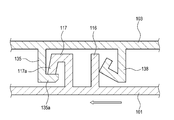
- the base member 101 has a pair of sandwiching pieces 116 and 117 as engaging portions.
- the front end side of one clamping piece 117 is formed in a substantially U shape to constitute a retaining claw 117a.
- an invitation inclined surface is formed which expands toward the base member 101 side.
- the cover 103 has an engaged portion 135 and an elastic piece 138.
- the engaged portion 135 is provided with an engaging protrusion 135a that can be engaged with the retaining claw 117a.
- the front end surface of the engaging protrusion 135a is cut out so as to have an inclined surface corresponding to the invitation inclined surface of the retaining claw 117a.
- the locking receiving portions 13, 42a, 64a and the locking pieces 33, 53, 74 are not restricted in shape as long as the cover is supported rotatably with respect to the base member, Alternatively, the latch piece may be provided on the base member, and the latch receiving portion may be provided on the cover.
Landscapes
- Engineering & Computer Science (AREA)
- Mechanical Engineering (AREA)
- Fittings On The Vehicle Exterior For Carrying Loads, And Devices For Holding Or Mounting Articles (AREA)
Abstract
Description
(1)車両の窓ガラスに固着されるベース部材(1,4,6)に対し互いに係合可能な相互係合手段により係合固定されて前記窓ガラスやベース部材などの設置部に保持される電子機器(9)を覆う車載用電子機器のカバー(3,5,7)であって、前記相互係合手段は、前記ベース部材及び前記カバーの一方に設けた係合部(15,45,65)と、他方に設けられて前記係合部と係合する被係合部(35,55,75)と、前記係合部を被係合部側へ付勢する付勢手段(38,48,68)とからなり、前記カバーを前記窓ガラスに向かって押し込むと、前記係合部が前記付勢手段により前記窓ガラス面に沿う向きに付勢された状態で前記被係合部に係合することを特徴としている。
(2)前記付勢手段は、前記ベース部材及び前記カバーの何れかに設けられている構成である。
Claims (8)
- 車両の窓ガラスに固着されるベース部材に対し互いに係合可能な相互係合手段により係合固定されて前記窓ガラスやベース部材などの設置部に保持される電子機器を覆う車載用電子機器のカバーであって、
前記相互係合手段は、前記ベース部材及び前記カバーの一方に設けた係合部と、他方に設けられて前記係合部と係合する被係合部と、前記係合部を前記被係合部側へ付勢する付勢手段とからなり、
前記カバーを前記窓ガラスに向かって押し込むと、前記係合部が前記付勢手段により前記窓ガラス面に沿う向きに付勢された状態で前記被係合部に係合することを特徴とする車載用電子機器のカバー。 - 前記付勢手段は、前記ベース部材及び前記カバーの何れかに設けられていることを特徴とする、請求項1に記載の車載用電子機器のカバー。
- 前記付勢手段は、前記係合部及び前記被係合部の何れかに設けられていることを特徴とする、請求項1に記載の車載用電子機器のカバー。
- 前記付勢手段は撓み変形可能な弾性片を有しており、前記係合部と前記被係合部の係合は前記カバーを前記弾性片の付勢方向に抗して移動することで解除可能となることを特徴とする請求項1から3の何れか一項に記載の車載用電子機器のカバー。
- 前記係合部は間に受空間を形成している一対の挟持片、及び前記一対の挟持片の一方に設けられて前記受空間に突出している抜止め用爪を有し、前記被係合部は前記抜止め用爪と係合可能な係合突起、及び前記弾性片を有しており、前記カバーを車両窓ガラスに向かって押し込むと、前記被係合部が前記弾性片の付勢方向への変位を伴って前記受空間に入り、前記係合突起が前記抜止め用爪に係合可能となることを特徴とする請求項4に記載の車載用電子機器のカバー。
- 前記係合部は間に受空間を形成している一対の挟持片、及び前記一対の挟持片の一方に設けられて前記受空間に突出している抜止め用爪を有していると共に、前記一対の挟持片の他方を前記弾性片として形成しており、前記被係合部は前記抜止め用爪と係合可能な係合突起を有しており、前記カバーを車両窓ガラスに向かって押し込むと、前記被係合部が前記弾性片の付勢方向への変位を伴って前記受空間に入り、前記係合突起が前記抜止め用爪に係合可能となることを特徴とする請求項4に記載の車載用電子機器のカバー。
- 前記係合部は前記窓ガラスの上側に向けて開口した凹所、及び前記弾性片を有しており、前記被係合部は前記凹所に係合する係合突起、及び前記弾性片に当接する突当部を有しており、前記カバーを車両窓ガラスに向かって押し込むと、前記突当部を介した前記弾性片の付勢方向への変位を伴って前記係合突起が前記凹所に係合可能となることを特徴とする請求項4に記載の車載用電子機器のカバー。
- 前記ベース部材及び前記カバーの一方の車両前後方向先端部に設けられた係止片と、他方の車両前後方向先端部に設けられた係止受部とを有し、前記係止片を前記係止受部に係合した状態で、前記係止片を軸として前記カバーを窓ガラスに向かって回転させ、前記係合部と前記被係合部を係合することを特徴とする請求項1から7の何れか一項に記載の車載用電子機器のカバー。
Priority Applications (4)
| Application Number | Priority Date | Filing Date | Title |
|---|---|---|---|
| US15/575,642 US10676040B2 (en) | 2015-05-22 | 2016-05-16 | Cover for onboard electronic device |
| JP2017520634A JP6494750B2 (ja) | 2015-05-22 | 2016-05-16 | 車載用電子機器のカバー |
| GB1718972.1A GB2554302B (en) | 2015-05-22 | 2016-05-16 | Cover for onboard electronic device |
| CN201680029549.0A CN107614326B (zh) | 2015-05-22 | 2016-05-16 | 车载用电子设备的盖 |
Applications Claiming Priority (2)
| Application Number | Priority Date | Filing Date | Title |
|---|---|---|---|
| JP2015-104239 | 2015-05-22 | ||
| JP2015104239 | 2015-05-22 |
Publications (1)
| Publication Number | Publication Date |
|---|---|
| WO2016190153A1 true WO2016190153A1 (ja) | 2016-12-01 |
Family
ID=57393906
Family Applications (1)
| Application Number | Title | Priority Date | Filing Date |
|---|---|---|---|
| PCT/JP2016/064480 Ceased WO2016190153A1 (ja) | 2015-05-22 | 2016-05-16 | 車載用電子機器のカバー |
Country Status (5)
| Country | Link |
|---|---|
| US (1) | US10676040B2 (ja) |
| JP (1) | JP6494750B2 (ja) |
| CN (1) | CN107614326B (ja) |
| GB (1) | GB2554302B (ja) |
| WO (1) | WO2016190153A1 (ja) |
Cited By (6)
| Publication number | Priority date | Publication date | Assignee | Title |
|---|---|---|---|---|
| JP2017171167A (ja) * | 2016-03-24 | 2017-09-28 | 本田技研工業株式会社 | センサブラケット |
| JP2019147529A (ja) * | 2018-02-28 | 2019-09-05 | スズキ株式会社 | 車載用電子機器のホルダ構造 |
| US10800343B2 (en) | 2016-11-18 | 2020-10-13 | Honda Motor Co., Ltd. | Onboard electronic device mounting structure |
| CN113874254A (zh) * | 2019-04-04 | 2021-12-31 | 法雷奥开关和传感器有限责任公司 | 用于将至少一个相机壳体固定到车辆的车辆部件的支架基部部件、相机壳体和相机系统 |
| JP2022170980A (ja) * | 2021-04-30 | 2022-11-11 | ロベルト・ボッシュ・ゲゼルシャフト・ミト・ベシュレンクテル・ハフツング | アダプター及びレーダーユニット |
| JP2023062498A (ja) * | 2021-10-21 | 2023-05-08 | トヨタ車体株式会社 | 組付構造 |
Families Citing this family (13)
| Publication number | Priority date | Publication date | Assignee | Title |
|---|---|---|---|---|
| EP3518033B1 (en) * | 2016-09-21 | 2021-04-14 | Hitachi Automotive Systems, Ltd. | Imaging device |
| EP3902706B1 (en) * | 2018-12-28 | 2023-11-01 | ZF Active Safety and Electronics US LLC | Driver assist system |
| DE112019007290T5 (de) * | 2019-05-08 | 2022-02-03 | Mitsubishi Electric Corporation | Fahrzeugbordkamera |
| EP3741624B1 (en) | 2019-05-23 | 2022-11-02 | Veoneer Sweden AB | A vehicle camera device |
| US11433827B2 (en) * | 2019-06-07 | 2022-09-06 | Volvo Car Corporation | Bracket assembly for securing a safety equipment module to a windowpane of a vehicle |
| GB201912157D0 (en) * | 2019-08-23 | 2019-10-09 | Pilkington Group Ltd | Windscreen |
| JP7278936B2 (ja) * | 2019-12-11 | 2023-05-22 | 株式会社ニフコ | ブラケット及び車載機器取付構造 |
| JP7390243B2 (ja) * | 2020-04-17 | 2023-12-01 | 株式会社ニフコ | 車載機器用ブラケット |
| JP7473504B2 (ja) | 2021-05-31 | 2024-04-23 | 株式会社ニフコ | デバイス取付構造 |
| CN113771767B (zh) * | 2021-09-07 | 2023-08-22 | 福建省万达汽车玻璃工业有限公司 | 支架装置、电子组件及车窗玻璃系统 |
| JP7590312B2 (ja) | 2021-12-06 | 2024-11-26 | 株式会社ニフコ | 機器取付構造 |
| EP4269175A1 (en) | 2022-04-28 | 2023-11-01 | Veoneer Sweden AB | A mounting bracket and a vehicle camera arrangement |
| US20250060174A1 (en) * | 2023-08-15 | 2025-02-20 | Valeo Systemes Thermiques | Clip fastener |
Citations (5)
| Publication number | Priority date | Publication date | Assignee | Title |
|---|---|---|---|---|
| JPH0488507U (ja) * | 1990-12-14 | 1992-07-31 | ||
| JPH04122250U (ja) * | 1991-04-17 | 1992-11-02 | 三ツ星ベルト株式会社 | 自動車内装品のインサート部材と付属部材の締結構造 |
| JP2005112052A (ja) * | 2003-10-03 | 2005-04-28 | Denso Corp | 車室内モジュールおよびインナーミラー |
| JP2008240887A (ja) * | 2007-03-27 | 2008-10-09 | Daikyo Nishikawa Kk | 取付部材の取付構造 |
| JP2013193558A (ja) * | 2012-03-19 | 2013-09-30 | Denso Corp | 車載カメラ |
Family Cites Families (14)
| Publication number | Priority date | Publication date | Assignee | Title |
|---|---|---|---|---|
| JPH0488507A (ja) * | 1990-08-01 | 1992-03-23 | Amada Metrecs Co Ltd | プログラム再開機能を有するcnc装置 |
| JPH04122250A (ja) * | 1990-09-11 | 1992-04-22 | Hiroshi Watanabe | 結石破砕装置の操作ワイヤー接続部 |
| CN101640340B (zh) * | 2008-07-29 | 2012-07-04 | Smk株式会社 | 连接器 |
| WO2011151714A1 (en) * | 2010-06-04 | 2011-12-08 | Lupin Limited | Modified sak gene for the production of recombinant proteins |
| US8339453B2 (en) * | 2010-07-14 | 2012-12-25 | Trw Automotive U.S. Llc | Apparatus for use in association with a vehicle |
| JP5672539B2 (ja) * | 2011-01-11 | 2015-02-18 | トヨタ自動車株式会社 | 車両用カメラユニットおよびブラケット |
| JP5733223B2 (ja) | 2012-01-13 | 2015-06-10 | トヨタ自動車株式会社 | 前方監視カメラカバー |
| JP5733243B2 (ja) | 2012-03-09 | 2015-06-10 | トヨタ自動車株式会社 | カメラカバー |
| JP6028382B2 (ja) * | 2012-04-27 | 2016-11-16 | 株式会社デンソー | 前方監視カメラ |
| JP5666656B2 (ja) * | 2013-07-08 | 2015-02-12 | 株式会社ホンダアクセス | 板状部材に対する部品の取付構造 |
| US20150042874A1 (en) * | 2013-08-08 | 2015-02-12 | Nidec Elesys Corporation | In-vehicle camera |
| JP6494569B2 (ja) * | 2016-07-20 | 2019-04-03 | 株式会社ニフコ | カメラユニット |
| US10800343B2 (en) * | 2016-11-18 | 2020-10-13 | Honda Motor Co., Ltd. | Onboard electronic device mounting structure |
| US10288986B2 (en) * | 2017-02-22 | 2019-05-14 | Trw Automotive U.S. Llc | Moderation of a driver assist camera enhancement via a vehicle windshield |
-
2016
- 2016-05-16 GB GB1718972.1A patent/GB2554302B/en active Active
- 2016-05-16 JP JP2017520634A patent/JP6494750B2/ja active Active
- 2016-05-16 CN CN201680029549.0A patent/CN107614326B/zh active Active
- 2016-05-16 US US15/575,642 patent/US10676040B2/en active Active
- 2016-05-16 WO PCT/JP2016/064480 patent/WO2016190153A1/ja not_active Ceased
Patent Citations (5)
| Publication number | Priority date | Publication date | Assignee | Title |
|---|---|---|---|---|
| JPH0488507U (ja) * | 1990-12-14 | 1992-07-31 | ||
| JPH04122250U (ja) * | 1991-04-17 | 1992-11-02 | 三ツ星ベルト株式会社 | 自動車内装品のインサート部材と付属部材の締結構造 |
| JP2005112052A (ja) * | 2003-10-03 | 2005-04-28 | Denso Corp | 車室内モジュールおよびインナーミラー |
| JP2008240887A (ja) * | 2007-03-27 | 2008-10-09 | Daikyo Nishikawa Kk | 取付部材の取付構造 |
| JP2013193558A (ja) * | 2012-03-19 | 2013-09-30 | Denso Corp | 車載カメラ |
Cited By (11)
| Publication number | Priority date | Publication date | Assignee | Title |
|---|---|---|---|---|
| JP2017171167A (ja) * | 2016-03-24 | 2017-09-28 | 本田技研工業株式会社 | センサブラケット |
| US10800343B2 (en) | 2016-11-18 | 2020-10-13 | Honda Motor Co., Ltd. | Onboard electronic device mounting structure |
| JP2019147529A (ja) * | 2018-02-28 | 2019-09-05 | スズキ株式会社 | 車載用電子機器のホルダ構造 |
| CN110203145A (zh) * | 2018-02-28 | 2019-09-06 | 铃木株式会社 | 车载用电子设备的保持件构造 |
| JP7067119B2 (ja) | 2018-02-28 | 2022-05-16 | スズキ株式会社 | 車載用電子機器のホルダ構造 |
| CN110203145B (zh) * | 2018-02-28 | 2022-11-15 | 铃木株式会社 | 车载用电子设备的保持件构造 |
| CN113874254A (zh) * | 2019-04-04 | 2021-12-31 | 法雷奥开关和传感器有限责任公司 | 用于将至少一个相机壳体固定到车辆的车辆部件的支架基部部件、相机壳体和相机系统 |
| JP2022170980A (ja) * | 2021-04-30 | 2022-11-11 | ロベルト・ボッシュ・ゲゼルシャフト・ミト・ベシュレンクテル・ハフツング | アダプター及びレーダーユニット |
| JP7709848B2 (ja) | 2021-04-30 | 2025-07-17 | ロベルト・ボッシュ・ゲゼルシャフト・ミト・ベシュレンクテル・ハフツング | アダプター及びレーダーユニット |
| JP2023062498A (ja) * | 2021-10-21 | 2023-05-08 | トヨタ車体株式会社 | 組付構造 |
| JP7668984B2 (ja) | 2021-10-21 | 2025-04-28 | トヨタ車体株式会社 | 組付構造 |
Also Published As
| Publication number | Publication date |
|---|---|
| GB2554302A (en) | 2018-03-28 |
| US20180154842A1 (en) | 2018-06-07 |
| JPWO2016190153A1 (ja) | 2017-12-21 |
| US10676040B2 (en) | 2020-06-09 |
| CN107614326A (zh) | 2018-01-19 |
| GB2554302B (en) | 2021-01-13 |
| JP6494750B2 (ja) | 2019-04-03 |
| GB201718972D0 (en) | 2018-01-03 |
| CN107614326B (zh) | 2020-08-14 |
Similar Documents
| Publication | Publication Date | Title |
|---|---|---|
| JP6494750B2 (ja) | 車載用電子機器のカバー | |
| US10921166B2 (en) | Sensor bracket | |
| CN107429729B (zh) | 线缆连接机构 | |
| US20040142594A1 (en) | Connector preventive of incomplete fitting | |
| JPWO2018092473A1 (ja) | 車載電子機器取付構造 | |
| US20150165982A1 (en) | Attaching structure for vehicle-mounted equipment | |
| US20150146350A1 (en) | Structure for holding display module | |
| US20070267315A1 (en) | Case | |
| US20180205210A1 (en) | Wire housing protector | |
| JP6470962B2 (ja) | 照明装置の取付構造、車両用内装部品及びドアパネル | |
| US10856428B2 (en) | Rattling prevention structure, electronic component module, electrical connection box, and wire harness | |
| WO2015190081A1 (ja) | 収容部、及びこれを備えた電気接続箱 | |
| JP6867881B2 (ja) | カウルカバー | |
| KR20170093197A (ko) | 전선 수용 프로텍터 | |
| JP6562294B2 (ja) | 車両の内装材におけるアンテナ保持構造 | |
| JP5054657B2 (ja) | サイドロック装置 | |
| JP5096967B2 (ja) | 車室内照明装置用ケース | |
| US7746281B2 (en) | Antenna mounting assembly | |
| JP5954232B2 (ja) | スイッチの取付構造 | |
| JP4861720B2 (ja) | ドアモール用クリップ | |
| JP4480174B2 (ja) | コーナーモールディング | |
| JP7639613B2 (ja) | 車載カメラ固定構造 | |
| JP7572272B2 (ja) | 樹脂構造体 | |
| WO2012137839A1 (ja) | クリップ | |
| JP7655146B2 (ja) | 車載カメラ固定構造 |
Legal Events
| Date | Code | Title | Description |
|---|---|---|---|
| 121 | Ep: the epo has been informed by wipo that ep was designated in this application |
Ref document number: 16799859 Country of ref document: EP Kind code of ref document: A1 |
|
| ENP | Entry into the national phase |
Ref document number: 2017520634 Country of ref document: JP Kind code of ref document: A |
|
| ENP | Entry into the national phase |
Ref document number: 201718972 Country of ref document: GB Kind code of ref document: A Free format text: PCT FILING DATE = 20160516 |
|
| WWE | Wipo information: entry into national phase |
Ref document number: 15575642 Country of ref document: US |
|
| NENP | Non-entry into the national phase |
Ref country code: DE |
|
| 122 | Ep: pct application non-entry in european phase |
Ref document number: 16799859 Country of ref document: EP Kind code of ref document: A1 |