US10856428B2 - Rattling prevention structure, electronic component module, electrical connection box, and wire harness - Google Patents
Rattling prevention structure, electronic component module, electrical connection box, and wire harness Download PDFInfo
- Publication number
- US10856428B2 US10856428B2 US16/568,239 US201916568239A US10856428B2 US 10856428 B2 US10856428 B2 US 10856428B2 US 201916568239 A US201916568239 A US 201916568239A US 10856428 B2 US10856428 B2 US 10856428B2
- Authority
- US
- United States
- Prior art keywords
- cover
- electronic component
- opening portion
- block member
- component module
- Prior art date
- Legal status (The legal status is an assumption and is not a legal conclusion. Google has not performed a legal analysis and makes no representation as to the accuracy of the status listed.)
- Active
Links
Images


Classifications
-
- H—ELECTRICITY
- H05—ELECTRIC TECHNIQUES NOT OTHERWISE PROVIDED FOR
- H05K—PRINTED CIRCUITS; CASINGS OR CONSTRUCTIONAL DETAILS OF ELECTRIC APPARATUS; MANUFACTURE OF ASSEMBLAGES OF ELECTRICAL COMPONENTS
- H05K7/00—Constructional details common to different types of electric apparatus
- H05K7/02—Arrangements of circuit components or wiring on supporting structure
- H05K7/026—Multiple connections subassemblies
-
- H—ELECTRICITY
- H02—GENERATION; CONVERSION OR DISTRIBUTION OF ELECTRIC POWER
- H02G—INSTALLATION OF ELECTRIC CABLES OR LINES, OR OF COMBINED OPTICAL AND ELECTRIC CABLES OR LINES
- H02G3/00—Installations of electric cables or lines or protective tubing therefor in or on buildings, equivalent structures or vehicles
- H02G3/02—Details
- H02G3/08—Distribution boxes; Connection or junction boxes
- H02G3/16—Distribution boxes; Connection or junction boxes structurally associated with support for line-connecting terminals within the box
-
- H—ELECTRICITY
- H05—ELECTRIC TECHNIQUES NOT OTHERWISE PROVIDED FOR
- H05K—PRINTED CIRCUITS; CASINGS OR CONSTRUCTIONAL DETAILS OF ELECTRIC APPARATUS; MANUFACTURE OF ASSEMBLAGES OF ELECTRICAL COMPONENTS
- H05K5/00—Casings, cabinets or drawers for electric apparatus
- H05K5/0026—Casings, cabinets or drawers for electric apparatus provided with connectors and printed circuit boards [PCB], e.g. automotive electronic control units
- H05K5/0069—Casings, cabinets or drawers for electric apparatus provided with connectors and printed circuit boards [PCB], e.g. automotive electronic control units having connector relating features for connecting the connector pins with the PCB or for mounting the connector body with the housing
-
- B—PERFORMING OPERATIONS; TRANSPORTING
- B60—VEHICLES IN GENERAL
- B60R—VEHICLES, VEHICLE FITTINGS, OR VEHICLE PARTS, NOT OTHERWISE PROVIDED FOR
- B60R16/00—Electric or fluid circuits specially adapted for vehicles and not otherwise provided for; Arrangement of elements of electric or fluid circuits specially adapted for vehicles and not otherwise provided for
- B60R16/02—Electric or fluid circuits specially adapted for vehicles and not otherwise provided for; Arrangement of elements of electric or fluid circuits specially adapted for vehicles and not otherwise provided for electric constitutive elements
- B60R16/023—Electric or fluid circuits specially adapted for vehicles and not otherwise provided for; Arrangement of elements of electric or fluid circuits specially adapted for vehicles and not otherwise provided for electric constitutive elements for transmission of signals between vehicle parts or subsystems
- B60R16/0238—Electrical distribution centers
-
- H—ELECTRICITY
- H05—ELECTRIC TECHNIQUES NOT OTHERWISE PROVIDED FOR
- H05K—PRINTED CIRCUITS; CASINGS OR CONSTRUCTIONAL DETAILS OF ELECTRIC APPARATUS; MANUFACTURE OF ASSEMBLAGES OF ELECTRICAL COMPONENTS
- H05K5/00—Casings, cabinets or drawers for electric apparatus
- H05K5/0026—Casings, cabinets or drawers for electric apparatus provided with connectors and printed circuit boards [PCB], e.g. automotive electronic control units
- H05K5/0039—Casings, cabinets or drawers for electric apparatus provided with connectors and printed circuit boards [PCB], e.g. automotive electronic control units having a tubular housing wherein the PCB is inserted longitudinally
-
- H—ELECTRICITY
- H05—ELECTRIC TECHNIQUES NOT OTHERWISE PROVIDED FOR
- H05K—PRINTED CIRCUITS; CASINGS OR CONSTRUCTIONAL DETAILS OF ELECTRIC APPARATUS; MANUFACTURE OF ASSEMBLAGES OF ELECTRICAL COMPONENTS
- H05K5/00—Casings, cabinets or drawers for electric apparatus
- H05K5/0026—Casings, cabinets or drawers for electric apparatus provided with connectors and printed circuit boards [PCB], e.g. automotive electronic control units
- H05K5/0073—Casings, cabinets or drawers for electric apparatus provided with connectors and printed circuit boards [PCB], e.g. automotive electronic control units having specific features for mounting the housing on an external structure
-
- B—PERFORMING OPERATIONS; TRANSPORTING
- B60—VEHICLES IN GENERAL
- B60R—VEHICLES, VEHICLE FITTINGS, OR VEHICLE PARTS, NOT OTHERWISE PROVIDED FOR
- B60R16/00—Electric or fluid circuits specially adapted for vehicles and not otherwise provided for; Arrangement of elements of electric or fluid circuits specially adapted for vehicles and not otherwise provided for
- B60R16/02—Electric or fluid circuits specially adapted for vehicles and not otherwise provided for; Arrangement of elements of electric or fluid circuits specially adapted for vehicles and not otherwise provided for electric constitutive elements
- B60R16/0207—Wire harnesses
Definitions
- the present invention relates to a rattling prevention structure including a bottomed cylindrical cover which includes a substantially rectangular opening portion, a block member which is inserted into the opening portion of the bottomed cylindrical cover, and an engagement mechanism which is configured to engage the block member with the opening portion.
- the present invention also relates to an electronic component module in which the rattling prevention structure is adopted, an electrical connection box including the electronic component module, and a wire harness including the electronic component module.
- the electronic component module includes a cover, a substrate which is housed inside the cover from an outside, and a connector block (block member) which is engaged with a rectangular opening portion of the cover.
- the electrical connection box includes the electronic component module and a frame which is configured to house and lock the electronic component module in the frame. Also, the electrical connection box is mounted on a vehicle. Examples of the electronic component module include a relay module and the like.
- the cover and the connector block are engaged by an engagement mechanism formed across the cover and the connector block.
- the engagement mechanism is disposed and formed in accordance with a long side part of the opening portion of the cover.
- the connector block is formed with a projection (a portion denoted by a reference numeral 55 in Patent Document 1 below) for stabilizing a state in which the cover and the connector block are engaged by the engagement mechanism.
- the projection is disposed and formed on a short side part of the connector block so as to restrict the long side part of the cover from moving away from an outer surface of the connector block (the long side part of the cover is bent in a direction in which the long side part of the cover is in close contact with the outer surface of the connector block by operation of the projection).
- Patent Literature 1 JP-A-2017-103916
- the present invention has been made in view of the above circumstances, and an aspect of the present invention is to provide a rattling prevention structure capable of preventing rattling. Another object of the present invention is to provide an electronic component module, an electrical connection box, and a wire harness, which use the rattling prevention structure.
- a rattling prevention structure for solving the above problems including: a bottomed cylindrical cover which includes a substantially rectangular opening portion; a block member which is inserted into the opening portion of the bottomed cylindrical cover; and an engagement mechanism which is configured to engage the block member with the opening portion, in which four pressing protrusions are formed at any one of four corner parts of the cover and four corner portions of the block member at the opening portion so as to bend four walls of the cover inward while displacing the four corner parts outward.
- the present invention having the feature of the first aspect, when the block member is inserted into the opening portion of the cover, the four walls of the cover are bent inward by operation of the four pressing protrusions, so that bent parts press the block member. Therefore, even when vibration occurs, rattling does not occur in an X direction and a Y direction (a longitudinal direction and a lateral direction). Further, when the bent parts press the block member, the cover and the block member are not likely to be disengaged from each other. Therefore, according to the present invention, rattling can be prevented even when vibration occurs, and thus an engagement state by the engagement mechanism can be maintained stable. If the engagement state can be maintained stable, reliability can also be enhanced.
- the four corner parts and the four corner portions are formed in tapered shapes facing each other.
- a tapered shape can be provided as a better shape.
- the rigidity of the cover can be increased by forming the four corner parts of the cover in tapered shapes. Therefore, cost can be reduced by changing a material of the cover to a low-cost material by the increased rigidity.
- An electronic component module for solving the above problems including: a substrate on which a plurality of electronic components are mounted, a bottomed cylindrical cover which includes a substantially rectangular opening portion, a block member which is inserted into the opening portion of the cover in a state that the substrate is held, and an engagement mechanism which is configured to engage the block member with the opening portion, in which the rattling prevention structure according to the first or the second aspect is used to prevent rattling between the cover and the block member.
- rattling does not occur between the cover and the block member, so that a better electronic component module can be provided.
- An electrical connection box for solving the above problems including the electronic component module according to the third aspect, a frame to which the electronic component module is assembled, and a lid member which is configured to cover a frame opening portion of the frame.
- the electronic component module having the effects described above is provided, so that a better electrical connection box can be provided.
- a wire harness according to a fifth aspect of the present invention for solving the above problems includes the electrical connection box according to the fourth aspect at an end and is wired in a vehicle.
- the electronic component module and the electrical connection box having the effects described above are provided so that a better wire harness can be provided.
- a wire harness according to a sixth aspect of the present invention for solving the above problems includes the electronic component module according to the third aspect at an end and is wired in a vehicle.
- the electronic component module having the effects described above is provided, so that a better wire harness can be provided.
- the cover of the electronic component module is formed with a bracket attachment and detachment portion which is attachable to and detachable from a bracket provided in the automobile.
- attachment of the electronic component module to an automobile can be facilitated.
- rattling prevention structure of the present invention it is possible to prevent rattling between the cover and the block member at the opening portion of the cover.
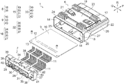
- FIG. 1 is a perspective view illustrating an electronic component module according to an embodiment of the present invention.
- FIG. 2 is a perspective view of the electronic component module in FIG. 1 as viewed from an arrow A direction.
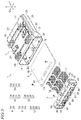
- FIG. 3 is an exploded perspective view illustrating a configuration of the electronic component module.
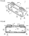
- FIGS. 4A and 4B illustrate a cover
- FIG. 4A is an enlarged perspective view of an opening portion side in FIG. 3
- FIG. 4B is viewed from an arrow C direction in FIG. 4A .
- FIGS. 5A and 5B illustrate a connector block
- FIG. 5A is an enlarged perspective view of FIG. 3
- FIG. 5B is viewed from an arrow D direction in FIG. 5A .
- FIG. 6 is a view of the connector block as viewed from an arrow E direction in FIG. 5A .
- FIG. 7 is a view of the connector block as viewed from an arrow F direction in FIG. 5A .
- FIGS. 8A to 8D are enlarged views of four main parts of the connector block which are indicated by circles G in FIGS. 6 and 7 .
- FIG. 9 is a view of the electronic component module in FIG. 2 as viewed from an arrow B direction.
- FIGS. 10A to 10D are enlarged views of four main parts of the electronic component module which are indicated by circles H in FIG. 9 .
- FIG. 11 schematically illustrates operation of four pressing protrusions in FIGS. 9 and 10 .
- An electronic component module includes a substrate on which a plurality of electronic components are mounted, a bottomed cylindrical cover which includes a substantially rectangular opening portion, a block member which is inserted into the opening portion of the cover in a state that the substrate is held, and an engagement mechanism which is configured to engage the block member with the opening portion.
- the rattling prevention structure is used to prevent rattling between the cover and the block member.
- four pressing protrusions are formed at any one of four corner parts of the cover and four corner portions of the block member at the opening portion. The four pressing protrusions are configured to bend four walls of the cover inward while displacing the four corner parts of the cover outward.
- FIG. 1 is a perspective view illustrating an electronic component module according to an embodiment of the present invention.
- FIG. 2 is a perspective view of the electronic component module in FIG. 1 as viewed from an arrow A direction.
- FIG. 3 is an exploded perspective view illustrating a configuration of the electronic component module.
- FIGS. 4A and 4B illustrate a cover.
- FIGS. 5A to 7 illustrate a connector block.
- FIGS. 8A to 8D are enlarged views of main parts of the connector block in FIGS. 6 and 7 .
- FIG. 9 is a view of the electronic component module in FIG. 2 as viewed from an arrow B direction.
- FIGS. 10A to 10D are enlarged views of main parts of the electronic component module in FIG. 9 .
- FIG. 11 schematically illustrates operation of four pressing protrusions in FIGS. 9 and 10 .
- an arrow P indicates an upper-lower direction
- an arrow Q indicates a left-right direction (X direction in FIG. 11 )
- an arrow R indicates a front-rear direction (Y direction in FIG. 11 ) (orientation is an example).
- the electronic component module 1 is disposed at a predetermined end 3 of a wire harness 2 wired in an automobile.
- the electronic component module 1 is connector-connected to a plurality of connectors (not illustrated) provided on the end 3 and is mounted at a predetermined position of the automobile in this connection state.
- An example of a mounting destination of the electronic component module 1 is a bracket 4 provided in an automobile.
- the electronic component module 1 is formed so as to be detachably attached to the bracket 4 .
- the electronic component module 1 may be mounted as follows. That is, an electrical connection box includes the electronic component module 1 , a frame to which the electronic component module 1 is assembled, and a lid member which is configured to cover a frame opening portion of the frame.
- the electrical connection box may be mounted on an end of a wire harness so as to be mounted on an automobile.
- the electronic component module 1 includes a substrate 5 , a cover 6 , and a connector block 7 (block member).
- the electronic component module 1 includes an engagement mechanism 8 which is configured to engage the cover 6 and the connector block 7 , and a rattling prevention structure 9 which is configured to prevent rattling between the cover 6 and the connector block 7 .
- the electronic component module 1 according to the present embodiment is connector-connected to a plurality of connectors (not illustrated), so that a “block member” described in claims is referred to as the “connector block 7 ”.
- the substrate 5 includes a substrate body 10 which is a plate-shaped member having a rectangular shape in a plan view.
- a desired circuit (not illustrated) is formed on a back surface which is a lower surface of the substrate body 10 .
- a large number of small through holes (not illustrated) are formed in the substrate body 10 .
- a plurality of electronic components (for example, relays and resistors) are mounted on a surface side of the substrate body 10 by using the through holes.
- An electronic component is connected to the circuit by soldering on a back surface side.
- a plurality of pin terminals 11 are also provided on the front surface side of the substrate body 10 . The pin terminals 11 are inserted into the through holes and connected to the circuit by soldering.
- the pin terminal 11 is formed in an L shape such that a proximal end side of the pin terminal 11 is disposed on a substrate front portion 12 of the substrate body 10 and the distal end side of the pin terminal 11 protrudes outward beyond an end portion 13 of the substrate front portion 12 .
- the distal end side of the pin terminal 11 passes through the connector block 7 and is disposed such that connector connection can be performed at the connector block 7 .
- the cover 6 is a resin molded product, and is formed in a bottomed cylindrical shape (box shape) including an opening portion 14 and an internal housing space S.
- the cover 6 is formed in the bottomed cylindrical shape (box shape) including an opening portion 14 which opens in a substantially rectangular shape, four walls 15 which are configured to form the opening portion 14 , four corner parts 16 which are one of features of the present invention, and a wall 17 at a position (position of a ceiling in orientation of the present embodiment) corresponding to a bottom of the cover 6 .
- the cover 6 is formed in the bottomed cylindrical shape (box shape) which can house and protect the substrate 5 .
- the cover 6 is formed in the bottomed cylindrical shape (box shape) so as to engage the connector block 7 with the opening portion 14 and to cover the connector block 7 .
- the opening portion 14 is formed to open in the substantially rectangular shape by the four walls 15 and the four corner parts 16 which will be described later.
- the opening portion 14 is formed to open in accordance with a shape of the connector block 7 .
- a plurality of cover side lock portions 18 which are engagement mechanisms 8 on a cover 6 side, and the four corner portions 16 , which are the rattling prevention structures 9 on the cover 6 side, are formed on an inner surface of the opening portion 14 .
- the opening portion 14 is referred to as an “opening portion” including not only an opening edge but also a part of a range in which the connector block 7 is inserted.
- “four” of the four walls 15 is a total of four: two of a first wall 19 and a second wall 20 which are at a predetermined interval in the front-rear direction indicated by the arrow R, and two of a third wall 21 and a fourth wall 22 which are at a predetermined interval in the left-right direction indicated by the arrow Q.
- the first wall 19 and the second wall 20 are formed to be larger than the third wall 21 and the fourth wall 22 .
- the first wall 19 and the second wall 20 are formed in accordance with a size of the substrate 5 in the plan view.
- the third wall 21 and the fourth wall 22 are formed in elongated rectangular walls.
- the third wall 21 and the fourth wall 22 are formed in accordance with a size of the substrate 5 in a front-back direction.
- the four walls 15 are formed such that the four corner parts 16 (described later) are interposed between the walls on the opening portion 14 side.
- the walls are formed to be continuous on a side which is not the opening portion 14 side.
- the first wall 19 of the four walls 15 is integrally formed with a bracket attachment and detachment portion 23 which is detachably attached to the bracket 4 provided in an automobile.
- the disposing and the shape of the bracket attachment and detachment portion 23 illustrated in the drawings is an example.
- the four corner parts 16 are the rattling prevention structure 9 on the cover 6 side as described above.
- the four corner parts 16 correspond to continuous parts of the four walls 15 at the opening portion 14 .
- the four corner parts 16 correspond to a first corner part 24 between the first wall 19 and the third wall 21 , a second corner part 25 between the second wall 20 and the third wall 21 , a third corner part 26 between the second wall 20 and the fourth wall 22 , and a fourth corner part 27 between the fourth wall 22 and the first wall 19 .
- the four corner parts 16 are formed in tapered parts facing four corner portions 33 , which will be described later, of the connector block 7 . As can be seen from the drawings, the four corner parts 16 are formed to be inclined at 45 degrees.
- the four corner parts 16 are formed to be sufficiently short in length as compared with the four walls 15 . Inner surfaces of the four corner parts 16 are formed in flat surfaces without unevenness. The inner surface is formed in a surface on which a pressing protrusion 43 , which will be described later, of the four corner portions 33 is in sliding contact, and is formed in a surface which is configured to receive operation from a pressing protrusion 43 .
- the cover side lock portion 18 is an engagement mechanism 8 formed on the cover 6 side as described above.
- one cover side lock portion 18 is formed on the first wall 19 and two cover side lock portions 18 are formed on the second wall 20 (the disposing and the number of the cover side lock portions 18 are one example).
- the cover side lock portion 18 is formed in a substantially claw-shaped protrusion protruding inward from inner surfaces of the first wall 19 and the second wall 20 .
- the cover side lock portion 18 is formed with a tapered or curved guide surface (reference numeral omitted) and a locking surface (reference numeral omitted) which is hooked by a block side lock portion 38 described later.
- the connector block 7 is assembled to a substrate front portion 12 of the substrate 5 and is formed so as to perform connector connection in the electronic component module 1 .
- the connector block 7 includes a block body 28 which is a resin molded product.
- the connector block 7 is formed to function as a connector by the distal end side of the pin terminal 11 of the substrate 5 passing through the block body 28 .
- the connector block 7 includes the block body 28 and (the distal end side) of the pin terminal 11 .
- FIGS. 3, 5, 6, and 7 three types of connector connection portions 29 to 31 are formed in the block body 28 .
- the connector connection portions 29 to 31 are configured to enable connector connection to a connector (not illustrated) of the wire harness 2 (see FIG. 1 ) and is formed in a cavity shape.
- the distal end side of the pin terminal 11 protrudes into each of the connector connection portions 29 to 31 .
- a side portion of the block body 28 is formed in an illustrated shape including four side portions 32 and four corner portions 33 .
- the side portion of the block body 28 is formed in accordance with a shape of the opening portion 14 of the cover 6 .
- the block body 28 is formed in a block-shaped member which is less likely to be bent than the cover 6 .
- the four side portions 32 includes a first side portion 34 and a second side portion 35 which face the first wall 19 and the second wall 20 in the opening 14 of the cover 6 , and a third side portion 36 and a fourth side portion 37 which face the third wall 21 and the fourth wall 22 in the opening 14 .
- a plurality of block side lock portions 38 which are engagement mechanisms 8 on a connector block 7 side, are formed on the first side portion 34 and the second side portion 35 .
- the block side lock portion 38 is the engagement mechanism 8 formed on the connector block 7 side as described above.
- the block side lock portion 38 is engaged with the cover side lock portion 18 in the opening portion 14 of the cover 6 and is disposed and formed in accordance with a position of the cover side lock portion 18 .
- the block side lock portion 38 is formed in a substantially claw-shaped protrusion protruding outward from a bottom of a part where outer surfaces of the first side portion 34 and the second side portion 35 are lowered.
- the block side lock portion 38 is formed with a tapered or curved guide surface (reference numeral omitted) and a locking surface (reference numeral omitted) which is hooked by the cover side lock portion 18 .
- the four corner portions 33 are one of the rattling prevention structures 9 on the connector block 7 side.
- the four corner portions 33 include a first corner portion 39 facing the first corner part 24 of the four corner parts 16 in the opening portion 14 of the cover 6 , a second corner portion 40 facing the second corner part 25 , a third corner portion 41 facing the third corner part 26 , and a fourth corner part 42 facing the fourth corner part 27 .
- the four corner portions 33 are formed in a tapered portion inclined at 45 degrees.
- the four corner portions 33 are formed to have sizes such that minute gaps are formed between outer surfaces of the four corner portions 33 and inner surfaces of the four corner parts 16 .
- the four corner portions 33 (the first corner portion 39 to the fourth corner portion 42 ) are formed with pressing protrusions 43 which are one of the features of the present invention.
- the pressing protrusion 43 is a rib-shaped portion protruding outward from the outer surfaces of the four corner portions 33 (the first corner portion 39 to the fourth corner portion 42 ), and is formed so as to extend straight in the upper-lower direction (see FIGS. 2 and 3 ) indicated by the arrow P (in the present embodiment, extend about half of a length of each of the four corner portions 33 ).
- the pressing protrusion 43 is formed to protrude slightly higher than a dimension corresponding to the minute gap. As can be seen from the drawings, the pressing protrusion 43 is a rib-shaped protrusion having a minute height.
- the pressing protrusion 43 is formed in a solid portion in which crushing does not occur (which is different from a general press-in protrusion that stops rattling by crushing).
- the pressing protrusion 43 is formed in the solid portion which can press the four corner parts 16 of the cover 6 outward.
- the pressing protrusions 43 may be formed on the four corner parts 16 instead of on the four corner portions 33 .
- the pressing protrusion 43 may be formed at any one of the four corner portions 33 and the four corner parts 16 as long as the pressing protrusion 43 is a source of a force that causes the four corner parts 16 to be displaced (see arrows in FIG. 11 ) outward.
- a reference numeral 44 in the pressing protrusion 43 indicates an inclined surface for guiding with respect to the cover 6 .
- the rattling prevention structure 9 includes the four corner parts 16 (the first wall 19 to the fourth wall 22 ) of the cover 6 , the four corner portions 33 (the first corner portion 39 to the fourth corner portion 42 ) of the connector block 7 , and the four pressing protrusions 43 formed on the four corner portions 33 .
- the four corner parts 16 are pressed outward by the four pressing protrusions 43
- the four walls 15 are bent inward by operation at this time as illustrated in FIG. 11 .
- a state of the engagement mechanism 8 that is, a state of engagement between the cover side lock portion 18 and the block side lock portion 38 is maintained stable without disengagement.
- the rattling prevention structure 9 when the connector block 7 is inserted into the opening portion 14 of the cover 6 , the four walls 15 of the cover 6 are bent inward by the operation of the four pressing protrusions 43 , so that bent parts press the four side portions 32 of the connector block 7 . Therefore, even when vibration occurs, rattling does not occur in an X direction and a Y direction (a longitudinal direction and a lateral direction) in FIG. 11 . Further, when the bent parts press the connector block 7 , the cover 6 and the connector block 7 are not likely to be disengaged from each other. Therefore, according to the rattling prevention structure 9 , rattling can be prevented even when vibration occurs, and thus the engagement state by the engagement mechanism 8 can be maintained stable. If the engagement state can be maintained stable, reliability can also be enhanced.
- the rattling prevention structure 9 is used. Therefore, rattling does not occur between the cover 6 and the connector block 7 , and as a result, a better electronic component module 1 can be provided. Further, according to the wire harness 2 , the electronic component module 1 having the effects described above is provided. Naturally, a better wire harness 2 can be provided.
Landscapes
- Engineering & Computer Science (AREA)
- Microelectronics & Electronic Packaging (AREA)
- Mechanical Engineering (AREA)
- Architecture (AREA)
- Civil Engineering (AREA)
- Structural Engineering (AREA)
- Connection Or Junction Boxes (AREA)
- Casings For Electric Apparatus (AREA)
Abstract
Description
Claims (10)
Applications Claiming Priority (2)
| Application Number | Priority Date | Filing Date | Title |
|---|---|---|---|
| JP2018-194890 | 2018-10-16 | ||
| JP2018194890A JP6804107B2 (en) | 2018-10-16 | 2018-10-16 | Anti-rattle structure, electronic component module, electrical junction box, and wire harness |
Publications (2)
| Publication Number | Publication Date |
|---|---|
| US20200120816A1 US20200120816A1 (en) | 2020-04-16 |
| US10856428B2 true US10856428B2 (en) | 2020-12-01 |
Family
ID=69954809
Family Applications (1)
| Application Number | Title | Priority Date | Filing Date |
|---|---|---|---|
| US16/568,239 Active US10856428B2 (en) | 2018-10-16 | 2019-09-11 | Rattling prevention structure, electronic component module, electrical connection box, and wire harness |
Country Status (4)
| Country | Link |
|---|---|
| US (1) | US10856428B2 (en) |
| JP (1) | JP6804107B2 (en) |
| CN (1) | CN111064144B (en) |
| DE (1) | DE102019214069B4 (en) |
Cited By (1)
| Publication number | Priority date | Publication date | Assignee | Title |
|---|---|---|---|---|
| US20200384933A1 (en) * | 2019-06-05 | 2020-12-10 | Hyundai Mobis Co., Ltd. | Electronic control unit for vehicle |
Families Citing this family (3)
| Publication number | Priority date | Publication date | Assignee | Title |
|---|---|---|---|---|
| DE102016219662B4 (en) * | 2016-10-11 | 2023-01-26 | Vitesco Technologies GmbH | Housing for accommodating a multi-part printed circuit board |
| JP7302424B2 (en) * | 2019-10-11 | 2023-07-04 | 株式会社オートネットワーク技術研究所 | electronic unit |
| JP7568679B2 (en) * | 2022-07-13 | 2024-10-16 | 矢崎総業株式会社 | Wire harness fixing structure |
Citations (5)
| Publication number | Priority date | Publication date | Assignee | Title |
|---|---|---|---|---|
| US6210208B1 (en) * | 1999-09-17 | 2001-04-03 | Emerson Electric Company | Quick connect terminal and terminal block |
| US20020101041A1 (en) * | 2001-01-30 | 2002-08-01 | Yazaki Corporation | Sealing structure of accessory module |
| US20170140863A1 (en) * | 2014-07-04 | 2017-05-18 | Autonetworks Technologies, Ltd. | Coil assembly, structure for attaching coil assembly, and electrical connection box |
| US20170164496A1 (en) | 2015-12-02 | 2017-06-08 | Yazaki Corporation | Engagement structure, electronic component module, and electrical connection box |
| US20200119532A1 (en) * | 2018-10-16 | 2020-04-16 | Yazaki Corporation | Engagement structure of cover and block member, electronic component module, electrical connection box, and wire harness |
Family Cites Families (7)
| Publication number | Priority date | Publication date | Assignee | Title |
|---|---|---|---|---|
| JP2008305869A (en) * | 2007-06-05 | 2008-12-18 | Fujitsu Ten Ltd | Accommodation case |
| JP5150291B2 (en) * | 2008-02-08 | 2013-02-20 | 矢崎総業株式会社 | Electrical junction box |
| JP2011048995A (en) * | 2009-08-26 | 2011-03-10 | Yazaki Corp | Connector |
| JP5789152B2 (en) | 2011-08-03 | 2015-10-07 | 矢崎総業株式会社 | Electrical junction box |
| JP6038977B2 (en) * | 2015-02-12 | 2016-12-07 | 矢崎総業株式会社 | Locking structure, electronic component unit, and wire harness |
| JP6342377B2 (en) * | 2015-12-02 | 2018-06-13 | 矢崎総業株式会社 | Drainage structure, electronic component module, and electrical junction box |
| JP6309554B2 (en) * | 2016-01-25 | 2018-04-11 | 矢崎総業株式会社 | Electrical junction box and wire harness |
-
2018
- 2018-10-16 JP JP2018194890A patent/JP6804107B2/en active Active
-
2019
- 2019-09-11 US US16/568,239 patent/US10856428B2/en active Active
- 2019-09-16 CN CN201910870191.XA patent/CN111064144B/en active Active
- 2019-09-16 DE DE102019214069.6A patent/DE102019214069B4/en active Active
Patent Citations (6)
| Publication number | Priority date | Publication date | Assignee | Title |
|---|---|---|---|---|
| US6210208B1 (en) * | 1999-09-17 | 2001-04-03 | Emerson Electric Company | Quick connect terminal and terminal block |
| US20020101041A1 (en) * | 2001-01-30 | 2002-08-01 | Yazaki Corporation | Sealing structure of accessory module |
| US20170140863A1 (en) * | 2014-07-04 | 2017-05-18 | Autonetworks Technologies, Ltd. | Coil assembly, structure for attaching coil assembly, and electrical connection box |
| US20170164496A1 (en) | 2015-12-02 | 2017-06-08 | Yazaki Corporation | Engagement structure, electronic component module, and electrical connection box |
| JP2017103916A (en) | 2015-12-02 | 2017-06-08 | 矢崎総業株式会社 | Engagement structure, electronic component module, and electrical junction box |
| US20200119532A1 (en) * | 2018-10-16 | 2020-04-16 | Yazaki Corporation | Engagement structure of cover and block member, electronic component module, electrical connection box, and wire harness |
Cited By (2)
| Publication number | Priority date | Publication date | Assignee | Title |
|---|---|---|---|---|
| US20200384933A1 (en) * | 2019-06-05 | 2020-12-10 | Hyundai Mobis Co., Ltd. | Electronic control unit for vehicle |
| US11858434B2 (en) * | 2019-06-05 | 2024-01-02 | Hyundai Mobis Co., Ltd. | Electronic control unit for vehicle having fixing member for coupling a cover portion and a base portion |
Also Published As
| Publication number | Publication date |
|---|---|
| DE102019214069B4 (en) | 2024-06-06 |
| DE102019214069A1 (en) | 2020-04-16 |
| JP6804107B2 (en) | 2020-12-23 |
| CN111064144B (en) | 2021-01-19 |
| JP2020065339A (en) | 2020-04-23 |
| CN111064144A (en) | 2020-04-24 |
| US20200120816A1 (en) | 2020-04-16 |
Similar Documents
| Publication | Publication Date | Title |
|---|---|---|
| US10856428B2 (en) | Rattling prevention structure, electronic component module, electrical connection box, and wire harness | |
| US11329462B2 (en) | Engagement structure of cover and block member, electronic component module, electrical connection box, and wire harness | |
| US9583928B2 (en) | Mounting structure of electronic component | |
| US11362493B2 (en) | Locking structure, electrical connection box, and wire harness | |
| US9559503B2 (en) | Electronic component unit | |
| US10039200B2 (en) | Engagement structure, electronic component module, and electrical connection box | |
| CN105210240B (en) | Joint connector | |
| CN106973541B (en) | Substrate holding structures, electronic component assemblies, and electrical junction boxes | |
| CN110582896B (en) | Connector for substrate | |
| CN110364870A (en) | Electronic component modules, electrical junction boxes, and wiring harnesses | |
| KR20140138729A (en) | Electric wire-to-substrate connector | |
| CN112072351A (en) | Electronic components unit | |
| US7748756B2 (en) | Lock mechanism | |
| JP2022035475A (en) | Cover detachment prevention structure | |
| CN107492730A (en) | Terminal for connector holding member, connector and arrangements of electric connection | |
| JP6940345B2 (en) | connector | |
| CN108933416A (en) | Electric circuit connection container | |
| CN106663894A (en) | Connector unit, sub-connector with frame, and sub-connector with cap | |
| CN111129838B (en) | Terminal cover | |
| JP4609858B2 (en) | Protector | |
| JP2016116347A (en) | Protector and wire with protector | |
| JP4364826B2 (en) | Electrical junction box linkage structure | |
| JP2019161925A (en) | Rattling suppression structure, electronic component module, electric connection box, and wiring harness | |
| JP2006073328A (en) | Case body and connector |
Legal Events
| Date | Code | Title | Description |
|---|---|---|---|
| AS | Assignment |
Owner name: YAZAKI CORPORATION, JAPAN Free format text: ASSIGNMENT OF ASSIGNORS INTEREST;ASSIGNORS:IMAIZUMI, YOSHIHITO;SATO, JUN;REEL/FRAME:050347/0918 Effective date: 20190826 |
|
| FEPP | Fee payment procedure |
Free format text: ENTITY STATUS SET TO UNDISCOUNTED (ORIGINAL EVENT CODE: BIG.); ENTITY STATUS OF PATENT OWNER: LARGE ENTITY |
|
| STPP | Information on status: patent application and granting procedure in general |
Free format text: NON FINAL ACTION MAILED |
|
| STPP | Information on status: patent application and granting procedure in general |
Free format text: RESPONSE TO NON-FINAL OFFICE ACTION ENTERED AND FORWARDED TO EXAMINER |
|
| STPP | Information on status: patent application and granting procedure in general |
Free format text: PUBLICATIONS -- ISSUE FEE PAYMENT RECEIVED |
|
| STCF | Information on status: patent grant |
Free format text: PATENTED CASE |
|
| AS | Assignment |
Owner name: YAZAKI CORPORATION, JAPAN Free format text: CHANGE OF ADDRESS;ASSIGNOR:YAZAKI CORPORATION;REEL/FRAME:063845/0802 Effective date: 20230331 |
|
| MAFP | Maintenance fee payment |
Free format text: PAYMENT OF MAINTENANCE FEE, 4TH YEAR, LARGE ENTITY (ORIGINAL EVENT CODE: M1551); ENTITY STATUS OF PATENT OWNER: LARGE ENTITY Year of fee payment: 4 |