WO2016186179A1 - 車両用灯具 - Google Patents
車両用灯具 Download PDFInfo
- Publication number
- WO2016186179A1 WO2016186179A1 PCT/JP2016/064927 JP2016064927W WO2016186179A1 WO 2016186179 A1 WO2016186179 A1 WO 2016186179A1 JP 2016064927 W JP2016064927 W JP 2016064927W WO 2016186179 A1 WO2016186179 A1 WO 2016186179A1
- Authority
- WO
- WIPO (PCT)
- Prior art keywords
- lens
- light
- light source
- lens unit
- unit
- Prior art date
Links
- 230000003287 optical effect Effects 0.000 claims description 18
- 239000004925 Acrylic resin Substances 0.000 claims description 4
- 229920000178 Acrylic resin Polymers 0.000 claims description 4
- 239000000463 material Substances 0.000 claims description 4
- 238000009826 distribution Methods 0.000 description 131
- 238000009792 diffusion process Methods 0.000 description 45
- 229910052782 aluminium Inorganic materials 0.000 description 10
- XAGFODPZIPBFFR-UHFFFAOYSA-N aluminium Chemical compound [Al] XAGFODPZIPBFFR-UHFFFAOYSA-N 0.000 description 10
- 239000000758 substrate Substances 0.000 description 8
- 230000002093 peripheral effect Effects 0.000 description 4
- 239000004065 semiconductor Substances 0.000 description 4
- 239000002699 waste material Substances 0.000 description 4
- 229920005668 polycarbonate resin Polymers 0.000 description 3
- 239000004431 polycarbonate resin Substances 0.000 description 3
- 230000003595 spectral effect Effects 0.000 description 3
- 238000010586 diagram Methods 0.000 description 2
- 239000007769 metal material Substances 0.000 description 2
- 238000004611 spectroscopical analysis Methods 0.000 description 2
- 238000003892 spreading Methods 0.000 description 2
- 230000007480 spreading Effects 0.000 description 2
- XUIMIQQOPSSXEZ-UHFFFAOYSA-N Silicon Chemical compound [Si] XUIMIQQOPSSXEZ-UHFFFAOYSA-N 0.000 description 1
- 230000004075 alteration Effects 0.000 description 1
- 230000008901 benefit Effects 0.000 description 1
- 238000006243 chemical reaction Methods 0.000 description 1
- 239000003086 colorant Substances 0.000 description 1
- 239000002131 composite material Substances 0.000 description 1
- 238000004512 die casting Methods 0.000 description 1
- 238000004049 embossing Methods 0.000 description 1
- 239000011521 glass Substances 0.000 description 1
- 230000020169 heat generation Effects 0.000 description 1
- 238000004519 manufacturing process Methods 0.000 description 1
- 238000000034 method Methods 0.000 description 1
- 239000000203 mixture Substances 0.000 description 1
- 230000004048 modification Effects 0.000 description 1
- 238000012986 modification Methods 0.000 description 1
- 229920003229 poly(methyl methacrylate) Polymers 0.000 description 1
- 239000004926 polymethyl methacrylate Substances 0.000 description 1
- 230000005855 radiation Effects 0.000 description 1
- 239000011347 resin Substances 0.000 description 1
- 229920005989 resin Polymers 0.000 description 1
- 239000010703 silicon Substances 0.000 description 1
- 229910052710 silicon Inorganic materials 0.000 description 1
Images


Classifications
-
- F—MECHANICAL ENGINEERING; LIGHTING; HEATING; WEAPONS; BLASTING
- F21—LIGHTING
- F21S—NON-PORTABLE LIGHTING DEVICES; SYSTEMS THEREOF; VEHICLE LIGHTING DEVICES SPECIALLY ADAPTED FOR VEHICLE EXTERIORS
- F21S41/00—Illuminating devices specially adapted for vehicle exteriors, e.g. headlamps
- F21S41/20—Illuminating devices specially adapted for vehicle exteriors, e.g. headlamps characterised by refractors, transparent cover plates, light guides or filters
- F21S41/285—Refractors, transparent cover plates, light guides or filters not provided in groups F21S41/24 - F21S41/2805
-
- F—MECHANICAL ENGINEERING; LIGHTING; HEATING; WEAPONS; BLASTING
- F21—LIGHTING
- F21S—NON-PORTABLE LIGHTING DEVICES; SYSTEMS THEREOF; VEHICLE LIGHTING DEVICES SPECIALLY ADAPTED FOR VEHICLE EXTERIORS
- F21S41/00—Illuminating devices specially adapted for vehicle exteriors, e.g. headlamps
- F21S41/10—Illuminating devices specially adapted for vehicle exteriors, e.g. headlamps characterised by the light source
- F21S41/14—Illuminating devices specially adapted for vehicle exteriors, e.g. headlamps characterised by the light source characterised by the type of light source
- F21S41/141—Light emitting diodes [LED]
- F21S41/143—Light emitting diodes [LED] the main emission direction of the LED being parallel to the optical axis of the illuminating device
-
- F—MECHANICAL ENGINEERING; LIGHTING; HEATING; WEAPONS; BLASTING
- F21—LIGHTING
- F21S—NON-PORTABLE LIGHTING DEVICES; SYSTEMS THEREOF; VEHICLE LIGHTING DEVICES SPECIALLY ADAPTED FOR VEHICLE EXTERIORS
- F21S41/00—Illuminating devices specially adapted for vehicle exteriors, e.g. headlamps
- F21S41/10—Illuminating devices specially adapted for vehicle exteriors, e.g. headlamps characterised by the light source
- F21S41/14—Illuminating devices specially adapted for vehicle exteriors, e.g. headlamps characterised by the light source characterised by the type of light source
- F21S41/141—Light emitting diodes [LED]
- F21S41/151—Light emitting diodes [LED] arranged in one or more lines
-
- F—MECHANICAL ENGINEERING; LIGHTING; HEATING; WEAPONS; BLASTING
- F21—LIGHTING
- F21S—NON-PORTABLE LIGHTING DEVICES; SYSTEMS THEREOF; VEHICLE LIGHTING DEVICES SPECIALLY ADAPTED FOR VEHICLE EXTERIORS
- F21S41/00—Illuminating devices specially adapted for vehicle exteriors, e.g. headlamps
- F21S41/10—Illuminating devices specially adapted for vehicle exteriors, e.g. headlamps characterised by the light source
- F21S41/19—Attachment of light sources or lamp holders
- F21S41/192—Details of lamp holders, terminals or connectors
-
- F—MECHANICAL ENGINEERING; LIGHTING; HEATING; WEAPONS; BLASTING
- F21—LIGHTING
- F21S—NON-PORTABLE LIGHTING DEVICES; SYSTEMS THEREOF; VEHICLE LIGHTING DEVICES SPECIALLY ADAPTED FOR VEHICLE EXTERIORS
- F21S41/00—Illuminating devices specially adapted for vehicle exteriors, e.g. headlamps
- F21S41/20—Illuminating devices specially adapted for vehicle exteriors, e.g. headlamps characterised by refractors, transparent cover plates, light guides or filters
- F21S41/25—Projection lenses
- F21S41/265—Composite lenses; Lenses with a patch-like shape
-
- F—MECHANICAL ENGINEERING; LIGHTING; HEATING; WEAPONS; BLASTING
- F21—LIGHTING
- F21S—NON-PORTABLE LIGHTING DEVICES; SYSTEMS THEREOF; VEHICLE LIGHTING DEVICES SPECIALLY ADAPTED FOR VEHICLE EXTERIORS
- F21S41/00—Illuminating devices specially adapted for vehicle exteriors, e.g. headlamps
- F21S41/20—Illuminating devices specially adapted for vehicle exteriors, e.g. headlamps characterised by refractors, transparent cover plates, light guides or filters
- F21S41/29—Attachment thereof
-
- F—MECHANICAL ENGINEERING; LIGHTING; HEATING; WEAPONS; BLASTING
- F21—LIGHTING
- F21S—NON-PORTABLE LIGHTING DEVICES; SYSTEMS THEREOF; VEHICLE LIGHTING DEVICES SPECIALLY ADAPTED FOR VEHICLE EXTERIORS
- F21S45/00—Arrangements within vehicle lighting devices specially adapted for vehicle exteriors, for purposes other than emission or distribution of light
- F21S45/40—Cooling of lighting devices
- F21S45/47—Passive cooling, e.g. using fins, thermal conductive elements or openings
-
- F—MECHANICAL ENGINEERING; LIGHTING; HEATING; WEAPONS; BLASTING
- F21—LIGHTING
- F21V—FUNCTIONAL FEATURES OR DETAILS OF LIGHTING DEVICES OR SYSTEMS THEREOF; STRUCTURAL COMBINATIONS OF LIGHTING DEVICES WITH OTHER ARTICLES, NOT OTHERWISE PROVIDED FOR
- F21V17/00—Fastening of component parts of lighting devices, e.g. shades, globes, refractors, reflectors, filters, screens, grids or protective cages
- F21V17/10—Fastening of component parts of lighting devices, e.g. shades, globes, refractors, reflectors, filters, screens, grids or protective cages characterised by specific fastening means or way of fastening
- F21V17/12—Fastening of component parts of lighting devices, e.g. shades, globes, refractors, reflectors, filters, screens, grids or protective cages characterised by specific fastening means or way of fastening by screwing
-
- F—MECHANICAL ENGINEERING; LIGHTING; HEATING; WEAPONS; BLASTING
- F21—LIGHTING
- F21S—NON-PORTABLE LIGHTING DEVICES; SYSTEMS THEREOF; VEHICLE LIGHTING DEVICES SPECIALLY ADAPTED FOR VEHICLE EXTERIORS
- F21S41/00—Illuminating devices specially adapted for vehicle exteriors, e.g. headlamps
- F21S41/10—Illuminating devices specially adapted for vehicle exteriors, e.g. headlamps characterised by the light source
- F21S41/19—Attachment of light sources or lamp holders
-
- F—MECHANICAL ENGINEERING; LIGHTING; HEATING; WEAPONS; BLASTING
- F21—LIGHTING
- F21S—NON-PORTABLE LIGHTING DEVICES; SYSTEMS THEREOF; VEHICLE LIGHTING DEVICES SPECIALLY ADAPTED FOR VEHICLE EXTERIORS
- F21S41/00—Illuminating devices specially adapted for vehicle exteriors, e.g. headlamps
- F21S41/20—Illuminating devices specially adapted for vehicle exteriors, e.g. headlamps characterised by refractors, transparent cover plates, light guides or filters
- F21S41/29—Attachment thereof
- F21S41/295—Attachment thereof specially adapted to projection lenses
-
- F—MECHANICAL ENGINEERING; LIGHTING; HEATING; WEAPONS; BLASTING
- F21—LIGHTING
- F21W—INDEXING SCHEME ASSOCIATED WITH SUBCLASSES F21K, F21L, F21S and F21V, RELATING TO USES OR APPLICATIONS OF LIGHTING DEVICES OR SYSTEMS
- F21W2102/00—Exterior vehicle lighting devices for illuminating purposes
- F21W2102/10—Arrangement or contour of the emitted light
- F21W2102/13—Arrangement or contour of the emitted light for high-beam region or low-beam region
-
- F—MECHANICAL ENGINEERING; LIGHTING; HEATING; WEAPONS; BLASTING
- F21—LIGHTING
- F21Y—INDEXING SCHEME ASSOCIATED WITH SUBCLASSES F21K, F21L, F21S and F21V, RELATING TO THE FORM OR THE KIND OF THE LIGHT SOURCES OR OF THE COLOUR OF THE LIGHT EMITTED
- F21Y2115/00—Light-generating elements of semiconductor light sources
- F21Y2115/10—Light-emitting diodes [LED]
Definitions
- the present invention relates to a vehicular lamp.
- a projection lens including a plurality of lenses disposed on an optical axis extending in the longitudinal direction of the vehicle, and a light source that is disposed on the rear side of the rear focal plane of the projection lens and irradiates the rear final surface of the projection lens And the rear focal plane of the projection lens and the rear final surface of the projection lens substantially coincide with each other, and the rear final surface of the projection lens is for scattering light emitted by the light source.
- Patent Document 1 describes the following. That is, with the configuration as described above, an image of a light source (or a light source image formed in the vicinity of the rear focal point of the projection lens by reflected light from the reflecting surface) arranged near the rear focal point of the projection lens is obtained. Rather than being projected, a rear final surface of the projection lens that is substantially coincident with the rear focal plane of the projection lens (for example, a fine uneven shape such as embossing applied to the rear final surface of the projection lens) As a result, a uniform illuminance distribution is formed on the final rear surface of the projection lens.
- this uniformed illuminance distribution is enlarged and inverted and projected forward through the projection lens, it is made uniform on the virtual vertical screen (for example, disposed approximately 25 m ahead from the front of the vehicle).
- a predetermined light distribution pattern of illuminance distribution can be formed.
- Patent Document 1 describes that since the projection lens is composed of a plurality of lenses, color fringes due to chromatic aberration can be suppressed as compared with a case where the projection lens is composed of a single lens. ing.
- Patent Document 1 does not consider the miniaturization of the vehicular lamp, but in recent years, it has been required to miniaturize the vehicular lamp.
- This invention is made
- a vehicular lamp according to the present invention includes a light source unit having a semiconductor-type light source, a second lens having a second lens unit disposed in front of the light source, and the light source and the second lens.
- a first lens having a first lens portion disposed between and converting a light cone of the light source into a cone connecting the second lens portion and a basic focal point of the second lens portion;
- the lens unit converts the light from the light source incident on the horizontal outer surface of the first lens unit to inward so as to be incident on the horizontal outer surface of the second lens unit. It is formed as follows.
- the second lens portion is formed so as to irradiate light from the outside to the inside from the center side toward the outside in the horizontal direction.
- an incident surface within a vertical range of the first lens unit in which an irradiation angle of light from the light source is a predetermined angle or less with respect to a light source optical axis of the light source is When viewed from the second lens unit side, the focal position of the second lens unit is formed so as to deviate in the vertical direction with respect to the basic focal point of the second lens unit.
- the first lens unit has a rear focal length of 3 mm or more and 10 mm or less, and the first lens is formed of a material having higher heat resistance than the second lens.
- the first lens is arranged such that the light emission center of the light source is located at the rear focal point of the first lens unit or in the vicinity of the rear focal point.
- the second lens is formed of an acrylic resin.
- the light source includes a plurality of light emitting chips
- the first lens includes a plurality of first lens portions corresponding to the light emitting chips.
- a plurality of second lens portions corresponding to the respective light emitting chips are also formed on the second lens.
- a low beam lamp unit disposed outside the vehicle is provided, and the light emitting chip, the first lens unit, and the first lens unit are disposed adjacent to the low beam lamp unit on the vehicle inner side.
- the two lens parts are arranged in the vertical direction.
- the vehicle lamp which can be reduced in size can be provided.
- the vehicular lamp according to the embodiment of the present invention is a vehicular headlamp (101R, 101L) provided on each of the left and right sides of the front of the vehicle 102 shown in FIG. 1, and is simply referred to as a vehicular lamp.
- the vehicular lamp according to the present embodiment includes a housing (not shown) that opens to the front side of the vehicle and an outer lens (not shown) that is attached to the housing so as to cover the opening, and is formed by the housing and the outer lens.
- a lamp unit 10 (see FIG. 2) and the like are disposed in the lamp chamber.
- FIG. 2 is an exploded perspective view of the lamp unit 10.
- the lamp unit 10 is disposed in front of the light source 30, a light source unit including a semiconductor light source 30 attached on the heat sink 20, a lens holder 40 attached on the heat sink 20, and the light source 30.
- the light source unit may be configured by using a plurality of semiconductor-type light sources 30 including the light emitting chip 32 and the aluminum mounting substrate 31, or on one aluminum mounting substrate 31 as in the present embodiment. You may make it comprise with the semiconductor-type light source 30 which provided the some light emitting chip 32.
- the heat sink 20 is a member that radiates heat generated by the light source 30, and is preferably formed using a metal material (for example, aluminum) or a resin material having high thermal conductivity.
- the plate-shaped heat sink 20 formed by press-working a metal material with high thermal conductivity is shown, it is not limited to this.
- a heat sink made of aluminum die casting or the like in which a heat radiation fin extending rearward is provided on the rear surface located on the opposite side of the front surface 21 on which the light source 30 is disposed may be used.
- the manufacturing cost can be reduced by forming the heat sink 20 by press working, from the viewpoint of cost, the plate-shaped heat sink 20 formed by press working as in the present embodiment. Is preferable.
- the surface 21 of the heat sink 20 is formed with a boss 22 for positioning when the light source 30 is attached and a screw fixing hole 23 for fixing a screw (not shown) for attaching the light source 30.
- a boss 24 for alignment when the first lens holder 41 of the lens holder 40 is attached and a screw (not shown) for attaching the first lens holder 41 are fixed to the surface 21 of the heat sink 20.
- a screw fixing hole 25 is formed.
- a boss 26 for positioning when the second lens holder 42 of the lens holder 40 is attached and a screw (not shown) for attaching the second lens holder 42 are fixed to the surface 21 of the heat sink 20.
- a screw fixing hole 27 is formed.
- the light source 30, the first lens holder 41, and the second lens holder 42 are aligned by the bosses 22, 24, and 26 provided on the surface 21 of the heat sink 20, respectively. Then, the light source 30, the first lens holder 41, and the second lens holder 42 can be fixed by fixing screws to the screw fixing holes 23, 25, and 27 provided on the surface 21 of the heat sink 20. It has become.
- the lamp unit 10 of the present embodiment forms a high beam light distribution pattern by superimposing three light distribution patterns of a short diffusion light distribution pattern, a middle diffusion light distribution pattern, and a large diffusion light distribution pattern. As shown in FIG. 2, the lamp unit 10 is provided with a light source 30 having a total of three light emitting chips 32, one for each light distribution pattern.
- the lamp unit 10 is an LED light source in which three light emitting chips 32 are provided on an aluminum mounting substrate 31 provided with a power feeding structure.
- the light source unit is configured by the light source 30 in which one aluminum mounting substrate 31 is provided as a common substrate and three light emitting chips 32 are provided on the aluminum mounting substrate 31.
- the light source unit includes three light emitting chips 32, for example, the light source unit may be configured using three light sources 30 each including one light emitting chip 32 and one aluminum mounting substrate 31. Even if it does in this way, it can be set as the light source part which provided the three light emitting chips like this embodiment.
- the aluminum mounting substrate 31 is provided with a boss hole 33 into which the boss 22 of the heat sink 20 is inserted, and a screw hole 34 through which a screw (not shown) for fixing to the heat sink 20 is passed. Then, after the light source 30 is disposed on the heat sink 20 so as to insert the boss 22 into the boss hole 33, a screw (not shown) is screwed into the screw fixing hole 23 of the heat sink 20 through the screw hole 34 and fixed. Thus, the light source 30 is fixed on the heat sink 20.
- the light source 30 is provided with one light emitting chip 32 for each light distribution pattern.
- the light source 30 is not necessarily limited to being provided for each light distribution pattern.
- a plurality of light emitting chips 32 may be provided as a set for one light distribution pattern.
- the number of light emitting chips 32 is increased, and the amount of heat generation is increased. Then, since the first lens 60 is deteriorated by heat, the first lens 60 may not be disposed close to the light source 30 for miniaturization.
- the first lens portion 61 itself of the first lens 60 is enlarged. The need to come out.
- the light emitting chip 32 used for each light distribution pattern is made one by one to suppress the amount of heat generated, and the first lens 60 can be disposed close to the light source 30 and each light distribution is arranged.
- the size of the first lens unit 61 necessary for receiving light without waste can be reduced. It is preferable to do.
- one light source 30 may be provided for each light distribution pattern, and the light source unit may be configured by a plurality of light sources 30.
- a plurality of light emitting chips 32 may be provided as a set for each light source 30, but each light source 30 is also used in the case where the light source unit is constituted by the plurality of light sources 30 from the viewpoint of downsizing as described above. It is preferable that the number of light emitting chips 32 provided in is one.
- the light emitting chip 32 may be partially chipped, and when the chip is partially chipped as described above, the chipped portion is disposed so as to be positioned on the lower side in the vertical direction. It is preferable to do this. By doing so, it is possible to form a good light distribution pattern by projecting the chipped portion upward and letting it escape above the light distribution pattern.
- the three light emitting chips 32 are used to form the three light distribution patterns of the short diffusion light distribution pattern, the middle diffusion light distribution pattern, and the large diffusion light distribution pattern. Without forming the light pattern, only the short diffusion light distribution pattern and the large diffusion light distribution pattern are formed, and the short diffusion light distribution pattern and the large diffusion light distribution pattern are overlapped to form a high beam light distribution pattern. good.
- the light emitting chip 32 may be provided with a total of two light emitting chips 32, that is, the light emitting chip 32 for the short diffusion light distribution pattern and the light emitting chip 32 for the large diffusion light distribution pattern.
- the light source unit is configured by a plurality of light sources 30, when only the short diffusion light distribution pattern and the large diffusion light distribution pattern are formed, the light source unit is configured by two light sources 30 corresponding to them. You can do it.
- the LED is used as the semiconductor light source 30, but a semiconductor light source such as a semiconductor laser (LD) may be used.
- the lens holder 40 includes a first lens holder 41 disposed on the light source 30 side and a second lens holder 42 disposed on the front side of the first lens holder 41.
- boss holes 41a for inserting the bosses 24 of the heat sink 20 and screw holes 41b for passing screws (not shown) are formed at both ends in the horizontal direction.
- the first lens holder 41 is disposed on the heat sink 20 so that the boss 24 of the heat sink 20 passes through the boss hole 41a, and then a screw (not shown) is screwed into the screw fixing hole 25 of the heat sink 20 through the screw hole 41b. By fixing them together, they can be attached to the heat sink 20.
- the second lens holder 42 is also formed with a boss hole 42a for inserting the boss 26 of the heat sink 20 at both ends in the horizontal direction and a screw hole 42b for passing a screw (not shown).
- the second lens holder 42 is disposed on the heat sink 20 so that the boss 26 of the heat sink 20 passes through the boss hole 42a, and then a screw (not shown) is screwed into the screw fixing hole 27 of the heat sink 20 through the screw hole 42b. By fixing them together, they can be attached to the heat sink 20.
- An opening 43 is formed in the center of the first lens holder 41. On both sides (upper and lower sides) of the central opening 43 in the vertical direction, receiving portions 44 for receiving both vertical sides (upper side and lower side) of the first lens are formed. A locking portion 45 that locks to the second lens holder 42 is formed on both surfaces (upper surface and lower surface) of the first lens holder 41 in the vertical direction.
- an opening 46 is also formed at the center of the second lens holder 42.
- Front wall portions 47 that receive both ends of the second lens 50 in the horizontal direction are formed on both sides in the horizontal direction on the front side of the central opening 46.
- Locking portions 48 that lock the first lens holder 41 are provided on both side walls (the left side wall and the right side wall) in the horizontal direction of the second lens holder 42.
- the first lens 60 is received by the receiving portion 44 of the first lens holder 41 and the second lens 50 is received by the front wall portion 47 of the second lens holder 42.
- the second lens 50 is held so as to be sandwiched between the first lens holder 41 and the second lens holder 42.
- the shade 70 is held so as to be sandwiched between the first lens 60 and the second lens 50.
- the first lens 60 has a horizontally long plate shape in the horizontal direction, and three first lens portions 61 corresponding to the respective light emitting chips 32 are formed.
- the first lens 60 is disposed so that the back focal point of the first lens unit 61 is located at the center or near the center of the light emitting chip 32 of the light source 30, that is, at the light emission center or near the light emission center of the light source 30.
- the first lens 60 can be disposed near the light source 30 if the rear focal length of the first lens portion 61 is formed to be as short as 3 mm or more and 10 mm or less.
- the first lens 60 is arranged in the vicinity of the light source 30 as described above, the first lens 60 may be thermally deteriorated due to the influence of heat from the light source 30.
- the first lens 60 is preferably formed of polycarbonate resin, silicon (SLR), glass, or the like that has excellent heat resistance.
- the first lens 60 is made of polycarbonate resin.
- An incident surface (light source side surface) on which light from the light source 30 of the first lens unit 61 is incident is formed as a composite quadric surface woven by two axes in the horizontal direction and the vertical direction.
- the horizontal axis and the vertical axis are both planar incident surfaces defined by straight lines.
- the horizontal axis is defined by a straight line
- the vertical axis is the inner side.
- An incident surface that is curved in the first lens portion 61 and defined by a curved curve may be used.
- the exit surface of the first lens unit 61 is formed as a free-form surface so that incident light is irradiated to the second lens 50 side as a predetermined exit pattern. The light distribution control of the first lens unit 61 will be described later.
- the first lens is adjusted accordingly.
- Two first lens portions 61 are formed in 60.
- the shade 70 is a member for shielding light so that light is not emitted from a portion other than the first lens portion 61 of the first lens 60. For this reason, three openings 71 are formed in the shade 70 according to the outer diameter of the first lens unit 61, and light emitted from the first lens unit 61 is not shielded while the first lens 60. Are formed so as to shield light other than the first lens portion 61. As described above, when the number of the first lens parts 61 is two, the number of the openings 71 is also two.
- the second lens 50 has a horizontally long plate shape in the horizontal direction, and three second lens portions 51 corresponding to the respective light emitting chips 32 are formed.
- the exit surface from which the light of the second lens unit 51 exits may be freely determined according to the required surface shape.
- the incident surface (surface on the first lens unit 61 side) on which the light of the second lens unit 51 is incident is formed as a free-form surface so that the light emitted from the emission surface has a predetermined emission pattern.
- the exit surface of the second lens portion 51 is made flat, and the entrance surface is formed as a free-form surface so that light emitted from the exit surface has a predetermined exit pattern.
- the light distribution control of the second lens unit 51 will be described later.
- the refractive index is different if the wavelength is different.
- the wavelength dependency of the refractive index is large, spectroscopy is likely to occur, and a blue spectral color is likely to appear in a part of the light distribution pattern.
- the second lens 50 is located on the front side of the first lens 60 and is not easily affected by the heat from the light source 30, the second lens 50 is spectrally separated using an acrylic resin such as PMMA having a small refractive index wavelength dependency. It is preferable to reduce the influence of. Therefore, as can be seen from the description of the first lens 60 and the second lens 50, in this embodiment, the first lens 60 is given priority over the polycarbonate resin (second lens 50 over the viewpoint of heat resistance). On the other hand, the second lens 50 is made of acrylic resin with priority given to the viewpoint of spectroscopy.
- the second lens is adjusted accordingly. 50, two second lens portions 51 are formed.
- FIG. 3 is a diagram illustrating the first lens unit 61 and the second lens unit 51 that form a large diffused light distribution pattern.
- FIG. 3 only the surface shapes of the entrance surfaces 62 and 52 and the exit surfaces 63 and 53 of the first lens unit 61 and the second lens unit 51 are shown.
- the central side of the emission surface 53 is reduced with respect to the light beam emitted from the emission surface 53 of the second lens unit 51. This is because when light rays are simply drawn from the light source 30 (light emitting chip 32) at an equal pitch, the light rays are not emitted from the center side of the emission surface 53.
- the light source 30 (light-emitting chip 32) emits a myriad of light without any gaps, naturally, some of these light rays are emitted from the center side of the emission surface 53. That is, the illustration is such that only a small amount of light is emitted from the center side of the emission surface 53 due to the thinning-out relationship when drawing light rays.
- the light emitting chip 32 of the light source 30 for forming a large diffusion light distribution pattern the incident surface 62 and the emission surface 63 of the first lens unit 61, and the incident surface 52 and the emission surface 53 of the second lens unit 51.
- Z indicates the optical axis of light from the light source 30 (light emitting chip 32) (hereinafter referred to as the light source optical axis Z), and X indicates the horizontal axis X orthogonal to the light source optical axis Z.
- P indicates a basic focal point P (rear focal point) of the second lens unit 51
- C indicates a cone C connecting the second lens unit 51 and the basic focal point P of the second lens unit 51.
- the basic focal point P of the second lens unit 51 is located considerably rearward of the light emitting chip 32.
- the light cone LC (spread of light) of the light emitting chip 32 spreads more rapidly than the cone C connecting the second lens unit 51 and the basic focal point P of the second lens unit 51. Therefore, the way of spreading the cone C and the way of spreading the light cone LC do not match.
- the cone C connecting the light cone LC from the light emitting chip 32 (light source 30) to the basic focal point P of the second lens unit 51 and the second lens unit 51.
- the first lens unit 61 that converts to match the spread state is arranged.
- the light incident on the incident surface 62 on the outer side in the horizontal direction of the first lens portion 61 can be converted into a state of a divergence angle similar to that of the cone C.
- the light is irradiated to the outside of the incident surface 52 of the lens unit 51.
- the first lens unit 61 further receives the light from the light source 30 (light emitting chip 32) incident on the incident surface 62 on the outer side in the horizontal direction of the first lens unit 61 on the incident surface on the outer side in the horizontal direction of the second lens unit 51.
- the second lens unit 51 is formed so as to be converted inward so as to be incident on the second lens unit 51.
- the horizontal angle of the first lens unit 61 in which the irradiation angle ⁇ of light from the light source 30 (light emitting chip 32) with respect to the incident surface 62 of the first lens unit 61 is 35 degrees or more.
- the light incident on the incident surface 62 on the outer side is converted inward so that the emitted light is incident on the incident surface 52 on the outer side in the horizontal direction of the second lens unit 51 when the light is emitted from the emitting surface 63.
- the emission surface 63 is formed so as to irradiate.
- the light incident on the incident surface 62 on the outer side in the horizontal direction of the first lens unit 61 having an irradiation angle ⁇ of 35 degrees or more is converted inward to irradiate the second lens unit 51. Otherwise, since the light does not enter the incident surface 52, the light incident on the incident surface 62 on the outer side in the horizontal direction of the first lens unit 61 having an irradiation angle ⁇ of 35 degrees or more is converted inward to the second lens unit 51. I try to irradiate. However, it goes without saying that it is not an essential requirement that the irradiation angle ⁇ be 35 degrees or more.
- the incident surface of the second lens unit 51 is converted into the state of the spread angle similar to the spread state of the cone C with the light incident on the incident surface 62 on the outer side in the horizontal direction of the first lens unit 61.
- the light incident on the incident surface 62 on the outer side in the horizontal direction of the first lens unit 61 on which the light to be irradiated outside 52 is incident is converted inward to irradiate the second lens unit 51. That's fine.
- the second lens unit 51 needs to be arranged considerably forward.
- a large second is set to match the spread of the light cone LC of the light source 30 (light emitting chip 32). It is necessary to use the lens unit 51.
- the first lens unit 61 is provided between the second lens unit 51 and the light source 30 so that the rear focal length is shortened and can be arranged close to the light source 30. .
- the spread angle of the light cone LC of the light source 30 (light emitting chip 32) is the same as the spread state of the cone C connecting the second lens unit 51 and the basic focal point P of the second lens unit 51. Convert to the state.
- the light incident on the incident surface 62 on the outer side in the horizontal direction of the first lens unit 61 which is off the incident surface 52 of the second lens unit 51 only by the conversion, is incident on the incident surface on the outer side in the horizontal direction of the second lens unit 51.
- the second lens unit 51 is irradiated with the light that is converted inward so as to be incident on the second lens unit 51.
- the second lens unit 51 can be arranged close to the light source 30 and the size of the second lens unit 51 can be greatly reduced, and the lamp unit 10 can be downsized. As a result, the vehicle lamp can be miniaturized.
- the lamp unit 10 having high light use efficiency that is, the vehicle lamp having high light use efficiency is obtained. It becomes possible.
- the second lens unit 51 is formed so as to irradiate light from the outside toward the inside in the horizontal direction from the center side.
- the incident surface 52 of the second lens unit 51 has two convex portions that are convex toward the light source 30 side outside the center in the horizontal direction.
- the center which is a portion where those convex shapes are connected, into a shape that is recessed inward
- the light incident on the center side of the incident surface 52 of the second lens unit 51 is irradiated horizontally outward from the emission surface 53
- Light incident on the outer side in the horizontal direction of the incident surface 52 of the second lens unit 51 is irradiated on the inner side (light source optical axis Z) side.
- light distribution control in which light is emitted to the outside on the center side and turned back in the middle and light is emitted to the inside on the outside may be referred to as open cross light distribution control.
- FIG. 4 shows the state of the light distribution pattern on the screen formed by the light from each light source by isoluminous lines.
- 4 shows the light distribution pattern on the screen on the upper side and the same figure as FIG. 3 on the lower side.
- the VU-VD line indicates a vertical line
- the HL-HR line Indicates a horizontal line.
- FIG. 4A shows the above-described large diffusion light distribution pattern
- FIG. 4B shows the middle diffusion light distribution pattern
- FIG. 4C shows the short diffusion light distribution pattern. It is shown.
- the basic configuration is the same as the portion that forms the large diffusion light distribution pattern.
- the shape of the incident surface 52 of the second lens unit 51 may be adjusted according to the horizontal spread of the light distribution pattern.
- the open cross light distribution control is performed also in the portion where the middle diffusion light distribution pattern and the short diffusion light distribution pattern are formed. Therefore, the point where the incident surface 52 of the second lens portion 51 has two convex portions that are convex toward the light source 30 on the outer side in the horizontal direction from the center is a portion that forms a large diffused light distribution pattern. However, the convex curvature may be moderated to match the horizontal spread of the light distribution pattern.
- the central side of the incident surface 52 of the second lens portion 51 that forms the middle diffused light distribution pattern and the short diffused light distribution pattern has a gentle convex curvature as described above.
- the dent is small.
- a high beam light distribution pattern is formed by multiplexing the large diffusion light distribution pattern, the middle light distribution pattern, and the short diffusion light distribution pattern thus formed.
- a light intensity difference appears between the part formed only by the large diffused light distribution pattern and the part where the middle diffused light distribution pattern is multiplexed, with the outer periphery contour of the middle diffused light distribution pattern as a boundary.
- a streak resulting from a difference in luminous intensity along the outer peripheral contour of the image appears.
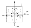
- FIG. 5 is a diagram schematically showing an incident angle 62 of light emitted from the light source 30 (light emitting chip 32) in the horizontal direction and the vertical direction on the incident surface 62 of the first lens unit 61 within a range of 50 degrees. is there.
- X indicates a horizontal direction axis X orthogonal to the light source optical axis Z, as described above.
- the light emitting chip 32 positioned on the light source optical axis Z shown as a point is shown. It is shown on the horizontal axis X for illustration.
- Y indicates a vertical axis Y orthogonal to the light source optical axis Z and the horizontal axis X.
- the light emitting chip 32 positioned on the light source optical axis Z shown as a point is described for explanation. Are shown on the vertical axis Y.
- the first lens unit 61 uses the light cone LC (see FIG. 3) of the light source 30 (light emitting chip 32) as the basic focal point P of the second lens unit 51 and the second lens unit 51. Is converted to cone C.
- the focal position of the second lens unit is the basic when viewed from the second lens unit 51 side.
- the incident surface 62 is formed so as to be defocused in the vertical direction with respect to the focal point P by a distance of approximately plus or minus numerical values (unit is mm) shown in FIG. Note that a numerical value in FIG. 5 that is positive indicates a focus shift upward in the vertical direction, and a negative value indicates a focus shift downward in the vertical direction.
- an angle ⁇ ′ is shown by drawing a line from the horizontal axis X to the incident surface 62, but this angle is incident from the light source 30 (light emitting chip 32) with the light source optical axis Z as a reference. It shows that the irradiation angle of the light applied to the surface 62 is within the range of the angle ⁇ ′ in the vertical direction. Then, with the light source optical axis Z as a reference, the incident surface 62 in which the irradiation angle of light irradiated from the light source 30 (light emitting chip 32) to the incident surface 62 is within a predetermined angle ⁇ ′ or less is in the vertical direction. It is formed to slip. In the present embodiment, the predetermined angle ⁇ ′ is 25 degrees.
- the entire range of the incident surface 62 in the vertical direction shown in FIG. 5 is such that the irradiation angle of the light irradiated from the light source 30 (light emitting chip 32) to the incident surface 62 with the light source optical axis Z as a reference.
- the range is 50 degrees (upper 50 degrees in the vertical direction, lower 50 degrees).
- an angle ⁇ is shown by drawing a line from the vertical direction axis Y to the incident surface, but this angle is from the light source 30 (light emitting chip 32) to the incident surface 62 with respect to the light source optical axis Z. It is shown that the irradiation angle of the light applied to is in a range within the angle ⁇ in the horizontal direction. As described above, the entire horizontal range of the incident surface 62 shown in FIG. 5 is such that the irradiation angle of light irradiated from the light source 30 (light emitting chip 32) to the incident surface 62 is 50 degrees (horizontal left side 50 degrees, (50 degrees on the right side).
- the configuration in which the focal position is shifted in the vertical direction is provided in the entire horizontal range of the incident surface 62 when viewed in the horizontal direction as shown in FIG.
- the irradiation angle of the light in the horizontal direction irradiated from the light source 30 (light emitting chip 32) to the incident surface 62 is different between the paraxial area within the angle ⁇ (25 degrees) and the area outside 25 degrees. .
- the light incident on this portion is irradiated to the front side so as to be slightly swung up and down.
- the edge of the light distribution pattern can be crushed.
- a structure for folding on the incident surface 62 of the first lens unit 61 that can be a relatively simple surface shape, a predetermined light distribution pattern according to the shape of the emission surface 53 It is not necessary to further add a configuration for wobbling the end of the light distribution pattern to the incident surface 52 of the second lens unit 51 that is designed to form. Thereby, it is not necessary to perform the light distribution control for forcing the second lens unit 51 to forcibly.
- FIG. 6 shows a high-beam light distribution pattern on the screen formed by the lamp unit 10 having the above-described configuration, represented by isoluminous lines.
- the VU-VD line indicates a vertical line
- the HL-HR line indicates a horizontal line.
- the outer periphery contour of the short diffused light distribution pattern is distorted, the streaks due to the light intensity difference appearing at the boundary between the portion where the short diffused light distribution pattern is multiplexed and the portion where the short diffused light distribution pattern is not formed are also high beam light distribution. It does not appear in the pattern. Therefore, a good high beam light distribution pattern is formed.
- each of the large diffusion light distribution pattern, the middle diffusion light distribution pattern, and the short diffusion light distribution pattern is multiplexed by being formed by open-cross light distribution control. It is possible to obtain a light distribution pattern without color unevenness in which the spectral colors are mixed and the spectral color is suppressed in the high beam light distribution pattern.
- the lamp unit 10 provided so that the part which forms each diffused light distribution pattern may be located in a horizontal direction was demonstrated.
- the portions for forming each diffused light distribution pattern are arranged as shown in FIG.
- FIG. 7 is a front view of the lamp unit 10, and the left side of the figure is the vehicle inner side and the right side of the figure is the vehicle outer side.
- a portion for forming a large diffused light distribution pattern which is the widest light distribution, is provided at the center of the lamp unit 10, and the lamp unit It is preferable to provide a portion for forming a middle diffused light distribution pattern and a short diffused light distribution pattern on the horizontal end side of 10.
- a portion for forming the short diffusion light distribution pattern is provided at the inner end of the vehicle in the horizontal direction to form the middle diffusion light distribution pattern. It is preferable that the portion is provided at the outer end of the vehicle in the horizontal direction.
- the lamp unit 10 is rotated 90 degrees from the state shown in FIG. It is preferable to make the size of the vehicular lamp smaller in the width direction by arranging it as a vertical type.
- the lamp unit 10 when the lamp unit 10 is of a vertical type, the orientation relationship among the light emitting chip 32, the first lens unit 61, and the second lens unit 51 described above is the same as the horizontal direction described above. If the relationship between the direction and the vertical direction is not maintained, the vertical direction and the horizontal direction of the formed light distribution pattern are interchanged. Therefore, in order to make the vertical lamp unit 10, the direction is not simply rotated by 90 degrees, but the respective parts forming the respective diffused light distribution patterns shown in FIG. 7 are maintained as they are. , Need to be formed to be stacked vertically.
- the portion that forms the large diffusion light distribution pattern is positioned on the lower side in the vertical direction, and the portion that forms the short diffusion light distribution pattern is in the middle in the vertical direction. It is preferable to locate the portion that forms the middle diffusion light distribution pattern at the top in the vertical direction.
- the part for forming the large diffusion light distribution pattern is a part for forming the middle diffusion light distribution pattern (see FIG. 4B) and a part for forming the short diffusion light distribution pattern ( Since the depression on the center side of the incident surface 52 of the second lens unit 51 is larger than that of the second lens unit 51 (see FIG. 4C), the second lens unit 51 is arranged on the lower side in the vertical direction where the lamp unit 10 is not visually observed. Can improve the appearance.
- the part (refer FIG.4 (b)) which forms a middle diffused light distribution pattern, and the part (refer FIG.4 (c)) which forms a short diffused light distribution pattern are the centers of the entrance plane 52 of the 2nd lens part 51.
- the vertical range of the incident surface 62 of the first lens unit 61 that causes the focal position to shift in the vertical direction is defined as the vertical direction of light from the light source 30 with respect to the light source optical axis Z of the light source 30.
- the range in which the irradiation angle is 25 degrees or less is set, but this range may be a range in which the irradiation angle is a predetermined angle ⁇ ′ or less selected from the range of 20 degrees to 30 degrees.
Landscapes
- Engineering & Computer Science (AREA)
- General Engineering & Computer Science (AREA)
- Physics & Mathematics (AREA)
- Microelectronics & Electronic Packaging (AREA)
- Optics & Photonics (AREA)
- Non-Portable Lighting Devices Or Systems Thereof (AREA)
Abstract
小型化が可能な車両用灯具を提供すること。本発明の車両用灯具は、半導体型の光源30を有する光源部と、光源30の前方に配置される第2レンズ部51を有する第2のレンズ50と、光源30と第2のレンズ50の間に配置され、光源30のライトコーンを第2レンズ部51と第2レンズ部51の基本焦点Pとを結ぶコーンに変換する第1レンズ部61を有する第1のレンズ60と、を備え、第1レンズ部61は、第1レンズ部61の水平方向外側の入射面62に入射する光源30からの光を第2レンズ部51の水平方向外側の入射面52に入射させるように内向きに変換して照射するように形成されている。
Description
本発明は車両用灯具に関するものである。
従来、車両前後方向に延びる光軸上に配置された複数のレンズを含む投影レンズと、前記投影レンズの後側焦点面より後方側に配置され、前記投影レンズの後側最終面を照射する光源と、を備え、前記投影レンズの後側焦点面と前記投影レンズの後側最終面とが略一致し、前記投影レンズの後側最終面には、前記光源が照射する光を散乱させるための処理が施されていることを特徴とする車両用灯具ユニットが知られている(特許文献1参照)。
そして、特許文献1には、以下のことが記載されている。すなわち、上記のような構成とすることで、投影レンズの後方側焦点近傍に配置された光源の像(又は反射面からの反射光で投影レンズの後方側焦点近傍に形成される光源像)が投影されるのではなく、投影レンズの後側焦点面と略一致した投影レンズの後側最終面(例えば、当該投影レンズの後側最終面に施されたシボ加工等の微細な凹凸形状)の作用で当該投影レンズの後側最終面上に均一化された照度分布が形成される。この均一化された照度分布が投影レンズを介して前方へ拡大反転投影されることとなるため、仮想鉛直スクリーン(例えば、車両前面から約25m前方に配置されている)上に、均一化された照度分布の所定配光パターンを形成することが可能となる。
また、特許文献1には、投影レンズが複数のレンズで構成されているため、投影レンズが単レンズで構成されている場合と比べ、色収差によるカラーフリンジを抑えることが可能となることが記載されている。
ところで、特許文献1では、車両用灯具の小型化に関しては考慮されていないが、近年、車両用灯具を小型化することが求められるようになっている。
本発明は、このような事情に鑑みなされたものであり、小型化が可能な車両用灯具を提供することを目的とする。
本発明は、このような事情に鑑みなされたものであり、小型化が可能な車両用灯具を提供することを目的とする。
本発明は、上記目的を達成するために以下の構成によって把握される。
(1)本発明の車両用灯具は、半導体型の光源を有する光源部と、前記光源の前方に配置される第2レンズ部を有する第2のレンズと、前記光源と前記第2のレンズの間に配置され、前記光源のライトコーンを前記第2レンズ部と前記第2レンズ部の基本焦点とを結ぶコーンに変換する第1レンズ部を有する第1のレンズと、を備え、前記第1レンズ部は、前記第1レンズ部の水平方向外側の入射面に入射する前記光源からの光を前記第2レンズ部の水平方向外側の入射面に入射させるように内向きに変換して照射するように形成されている。
(2)上記(1)の構成において、前記第2レンズ部は、中央側から水平方向外側に向かって光を外側から内側に照射するように形成されている。
(3)上記(1)の構成において、前記光源の光源光軸を基準として前記光源からの光の照射角度が所定角度以下となる前記第1レンズ部の鉛直方向の範囲内の入射面は、前記第2レンズ部側から見たときに、第2レンズ部の焦点位置が前記第2レンズ部の基本焦点に対して鉛直方向にズレるように形成されている。
(4)上記(1)の構成において、前記第1レンズ部は、後方焦点距離が3mm以上10mm以下であり、前記第1のレンズは、前記第2のレンズよりも高耐熱性の材料で形成されており、前記第1のレンズは、第1レンズ部の後方焦点若しくは後方焦点近傍に前記光源の発光中心が位置するように配置されている。
(5)上記(1)の構成において、前記第2のレンズは、アクリル系樹脂で形成されている。
(6)上記(1)の構成において、前記光源に設けられる発光チップの一部に欠けがある場合には、欠けがある部分が鉛直方向下側に位置するように、前記発光チップが配置されている。
(7)上記(1)の構成において、前記光源には、複数の発光チップが設けられており、前記第1のレンズには、それぞれの前記発光チップに対応する複数の前記第1レンズ部が形成されているとともに、前記第2のレンズにもそれぞれの前記発光チップに対応する複数の前記第2レンズ部が形成されている。
(8)上記(7)の構成において、車両外側に配置されるロービーム用灯具ユニットを備え、前記ロービーム用灯具ユニットの車両内側となる隣の位置に前記発光チップ、前記第1レンズ部および前記第2レンズ部が鉛直方向に並ぶように配置されている。
本発明によれば、小型化が可能な車両用灯具を提供することができる。
以下、添付図面を参照して、本発明を実施するための形態(以下、「実施形態」と称する)について詳細に説明する。実施形態の説明の全体を通して同じ要素には同じ番号を付している。また、実施形態及び図中において、特に断りがない場合、「前」、「後」は、各々、車両の「前進方向」、「後進方向」を示し、「上」、「下」、「左」、「右」は、各々、車両に乗車する運転者から見た方向を示す。
本発明の実施形態に係る車両用灯具は、図1に示す車両102の前方の左右のそれぞれに設けられる車両用前照灯(101R、101L)であり、以下では単に車両用灯具と記載する。
本実施形態の車両用灯具は、車両前方側に開口したハウジング(図示せず)と開口を覆うようにハウジングに取付けられるアウターレンズ(図示せず)を備え、ハウジングとアウターレンズとで形成される灯室内に灯具ユニット10(図2参照)などが配置されている。
(灯具ユニット)
図2は、灯具ユニット10の分解斜視図である。
図2に示すように、灯具ユニット10は、ヒートシンク20と、ヒートシンク20上に取付けられる半導体型の光源30からなる光源部と、ヒートシンク20上に取付けられるレンズホルダ40と、光源30の前方に配置される第2のレンズ50と、第2のレンズ50と光源30の間に配置される第1のレンズ60と、第1のレンズ60と第2のレンズ50の間に配置されるシェード70と、を備えている。
なお、光源部は、発光チップ32とアルミ実装基板31とで構成される半導体型の光源30を複数用いて構成されていても良いし、本実施形態のように、1つのアルミ実装基板31に複数の発光チップ32を設けた半導体型の光源30で構成するようにしても良い。したがって、以下の説明では、単に光源30とのみ記載して光源部との記載を省略し、光源30と光源部を分けて説明する必要がある部分についてのみ光源部との表現を用いて説明する。
(ヒートシンク)
ヒートシンク20は、光源30が発生する熱を放熱する部材であり、熱伝導率の高い金属材料(例えば、アルミ等)や樹脂材料を用いて成形されるのが好適である。
ヒートシンク20は、光源30が発生する熱を放熱する部材であり、熱伝導率の高い金属材料(例えば、アルミ等)や樹脂材料を用いて成形されるのが好適である。
本実施形態では、熱伝導率の高い金属材料をプレス加工することで形成した板状のヒートシンク20の場合を示しているが、これに限られるものではない。例えば、光源30が配置される表面21と反対側に位置する裏面に後方に伸びる放熱フィンを設けるようにしたアルミダイカスト製のヒートシンクなどでも良い。
但し、プレス加工でヒートシンク20を形成するようにする方が、製造コストを抑えることができるので、コスト的な面からすれば、本実施形態のように、プレス加工で形成した板状のヒートシンク20とするのが好適である。
ヒートシンク20の表面21には、光源30を取付けるときの位置合わせのためのボス22と、光源30を取付けるためのネジ(図示せず)を固定するネジ固定孔23とが形成されている。
また、ヒートシンク20の表面21には、レンズホルダ40の第1レンズホルダ41を取付けるときの位置合わせのためのボス24と、第1レンズホルダ41を取付けるためのネジ(図示せず)を固定するネジ固定孔25とが形成されている。
さらに、ヒートシンク20の表面21には、レンズホルダ40の第2レンズホルダ42を取付けるときの位置合わせのためのボス26と、第2レンズホルダ42を取付けるためのネジ(図示せず)を固定するネジ固定孔27とが形成されている。
このように、ヒートシンク20の表面21に設けられたボス22、24、及び、26で、それぞれ光源30、第1レンズホルダ41及び第2レンズホルダ42が位置合わせされる。そして、ヒートシンク20の表面21に設けられたネジ固定孔23、25、及び、27にネジを固定するようにして、それぞれ光源30、第1レンズホルダ41及び第2レンズホルダ42が固定できるようになっている。
(光源)
本実施形態の灯具ユニット10は、ショート拡散配光パターン、ミドル拡散配光パターン及びラージ拡散配光パターンの3つの配光パターンを重ね合わせることでハイビーム配光パターンを形成するようになっている。図2に示すように、灯具ユニット10には、それぞれの配光パターン用に1つずつ合計3つの発光チップ32を有する光源30が設けられる。
本実施形態の灯具ユニット10は、ショート拡散配光パターン、ミドル拡散配光パターン及びラージ拡散配光パターンの3つの配光パターンを重ね合わせることでハイビーム配光パターンを形成するようになっている。図2に示すように、灯具ユニット10には、それぞれの配光パターン用に1つずつ合計3つの発光チップ32を有する光源30が設けられる。
より具体的には、灯具ユニット10は、給電構造を設けたアルミ実装基板31上に3つの発光チップ32を設けたLED光源である。
なお、上述したように、本実施形態では、共通基板として1つのアルミ実装基板31を設け、そのアルミ実装基板31上に3つの発光チップ32を設ける態様とした光源30で光源部を構成し、光源部が3つの発光チップ32を有するものとしているが、例えば、1つの発光チップ32と1つのアルミ実装基板31からなる光源30を3つ用いて光源部を構成するようにしても良い。このようにしても、本実施形態と同様に、3つの発光チップを設けた光源部とすることができる。
アルミ実装基板31には、ヒートシンク20のボス22が挿入されるボス孔33とヒートシンク20に固定するときのネジ(図示せず)を通すためのネジ孔34とが設けられている。そして、ボス22をボス孔33に挿入するように光源30がヒートシンク20上に配置された後、ネジ孔34を通してネジ(図示せず)をヒートシンク20のネジ固定孔23に螺合させて固定することで光源30はヒートシンク20上に固定される。
本実施形態では、光源30は各配光パターン用に1つずつ発光チップ32を設けたものとしているが、必ずしも各配光パターン用に1つずつ設けることに限定される必要はない。例えば、1つの配光パターン用に複数の発光チップ32をセットとして設けるようにしてもよい。しかしながら、そのように1つの配光パターン用に複数の発光チップ32をセットとして設けるようにすると、発光チップ32の数が増えることになるので発熱量が増加することになる。
そうすると、第1のレンズ60が熱による劣化を起こすことになるため、小型化のために、第1のレンズ60を光源30に近づけて配置できないようになる場合がある。
そうすると、第1のレンズ60が熱による劣化を起こすことになるため、小型化のために、第1のレンズ60を光源30に近づけて配置できないようになる場合がある。
また、発光チップ32の数を増やすと、その分だけ発光面が大きくなるため、その大きい発光面からの光を無駄なく受けるためには、第1のレンズ60の第1レンズ部61自体を大きくする必要が出てくる。
このため、小型化のためには、各配光パターン用に用いる発光チップ32を1つずつとして発熱量を抑え、第1のレンズ60を光源30に近づけて配置できるようにするとともに、各配光パターン用に用いる発光チップ32を1つずつとして発光面積の小さい点光源に近い状態とすることで、光を無駄なく受けるために必要な第1レンズ部61の大きさ自体を小さくできるようにすることが好適である。
なお、各配光パターン用に1つずつ光源30を設けて複数の光源30で光源部を構成するようにしても良い。この場合も、各光源30毎に複数の発光チップ32をセットとして設けるようにしても良いが、上述した小型化の観点から複数の光源30で光源部を構成するような場合でも、各光源30に設けられる発光チップ32の数は1つとするのが好適である。
なお、各配光パターン用に1つずつ光源30を設けて複数の光源30で光源部を構成するようにしても良い。この場合も、各光源30毎に複数の発光チップ32をセットとして設けるようにしても良いが、上述した小型化の観点から複数の光源30で光源部を構成するような場合でも、各光源30に設けられる発光チップ32の数は1つとするのが好適である。
ところで、発光チップ32は、メーカーによっては、一部に欠けがある場合があり、このように一部に欠けがある場合には、その欠けのある部分が鉛直方向下側に位置するように配置するのが好適である。
このようにすることで欠けの部分を上方に投影するようにして、配光パターンの上方に逃がすようにすることで良好な配光パターンを形成することが可能となる。
このようにすることで欠けの部分を上方に投影するようにして、配光パターンの上方に逃がすようにすることで良好な配光パターンを形成することが可能となる。
なお、本実施形態では、ショート拡散配光パターン、ミドル拡散配光パターン及びラージ拡散配光パターンの3つの配光パターンを形成するために、3つの発光チップ32を用いているが、ミドル拡散配光パターンを形成せず、ショート拡散配光パターン及びラージ拡散配光パターンだけを形成して、ショート拡散配光パターン及びラージ拡散配光パターンを重ね合わせてハイビーム配光パターンを形成するようにしても良い。
このような場合には、発光チップ32は、ショート拡散配光パターン用の発光チップ32と、ラージ拡散配光パターン用の発光チップ32との合計2つの発光チップ32が設けられていれば良い。
なお、複数の光源30で光源部を構成する場合も同様に、ショート拡散配光パターン及びラージ拡散配光パターンだけを形成する時には、それらに対応して2つの光源30で光源部を構成するようにすればよい。
また、本実施形態では、半導体型の光源30としてLEDを用いている場合について示しているが、例えば、半導体レーザ(LD)のような半導体型の光源を用いるようにしても良い。
なお、複数の光源30で光源部を構成する場合も同様に、ショート拡散配光パターン及びラージ拡散配光パターンだけを形成する時には、それらに対応して2つの光源30で光源部を構成するようにすればよい。
また、本実施形態では、半導体型の光源30としてLEDを用いている場合について示しているが、例えば、半導体レーザ(LD)のような半導体型の光源を用いるようにしても良い。
(レンズホルダ)
レンズホルダ40は、光源30側に配置される第1レンズホルダ41と、第1レンズホルダ41の前方側に配置される第2レンズホルダ42とからなる。
第1レンズホルダ41には、ヒートシンク20のボス24を挿入するボス孔41aとネジ(図示せず)を通すネジ孔41bとが水平方向の両端に形成されている。第1レンズホルダ41は、ボス孔41aにヒートシンク20のボス24を通すようにしてヒートシンク20上に配置された後、ネジ孔41bを通してネジ(図示せず)をヒートシンク20のネジ固定孔25に螺合させて固定することでヒートシンク20に取付けられるようになっている。
レンズホルダ40は、光源30側に配置される第1レンズホルダ41と、第1レンズホルダ41の前方側に配置される第2レンズホルダ42とからなる。
第1レンズホルダ41には、ヒートシンク20のボス24を挿入するボス孔41aとネジ(図示せず)を通すネジ孔41bとが水平方向の両端に形成されている。第1レンズホルダ41は、ボス孔41aにヒートシンク20のボス24を通すようにしてヒートシンク20上に配置された後、ネジ孔41bを通してネジ(図示せず)をヒートシンク20のネジ固定孔25に螺合させて固定することでヒートシンク20に取付けられるようになっている。
同様に、第2レンズホルダ42にも、水平方向の両端にヒートシンク20のボス26を挿入するボス孔42aとネジ(図示せず)を通すネジ孔42bとが形成されている。第2レンズホルダ42は、ボス孔42aにヒートシンク20のボス26を通すようにしてヒートシンク20上に配置された後、ネジ孔42bを通してネジ(図示せず)をヒートシンク20のネジ固定孔27に螺合させて固定することでヒートシンク20に取付けられるようになっている。
また、第1レンズホルダ41の中央には、開口43が形成されている。その中央の開口43の鉛直方向の両側(上側及び下側)には、第1のレンズの鉛直方向の両辺(上側の辺及び下側の辺)を受ける受け部44が形成されている。
そして、第1レンズホルダ41の鉛直方向の両面(上側の面及び下側の面)には、第2レンズホルダ42に係止する係止部45が形成されている。
そして、第1レンズホルダ41の鉛直方向の両面(上側の面及び下側の面)には、第2レンズホルダ42に係止する係止部45が形成されている。
一方、第2レンズホルダ42の中央にも開口46が形成されている。その中央の開口46の前方側の水平方向の両側に第2のレンズ50の水平方向の両端を受ける前面壁部47が形成されている。
そして、第2レンズホルダ42の水平方向の両側壁(左側の側壁及び右側の側壁)には、第1レンズホルダ41に係止する係止部48が設けられている。
そして、第2レンズホルダ42の水平方向の両側壁(左側の側壁及び右側の側壁)には、第1レンズホルダ41に係止する係止部48が設けられている。
したがって、第1のレンズ60が第1レンズホルダ41の受け部44に受けられるとともに、第2のレンズ50が第2レンズホルダ42の前面壁部47で受けられた状態で、第1のレンズ60と第2のレンズ50は、第1レンズホルダ41と第2レンズホルダ42とで挟まれるようにして保持される。
なお、シェード70は、第1のレンズ60と第2のレンズ50との間に挟まれるように保持されることになる。
なお、シェード70は、第1のレンズ60と第2のレンズ50との間に挟まれるように保持されることになる。
(第1のレンズ)
第1のレンズ60は、水平方向に横長の板状であり、それぞれの発光チップ32に対応する3つの第1レンズ部61が形成されている。第1のレンズ60は、第1レンズ部61の後方焦点が光源30の発光チップ32の中心若しくは中心近傍、つまり、光源30の発光中心若しくは発光中心近傍に位置するように配置される。
第1のレンズ60は、水平方向に横長の板状であり、それぞれの発光チップ32に対応する3つの第1レンズ部61が形成されている。第1のレンズ60は、第1レンズ部61の後方焦点が光源30の発光チップ32の中心若しくは中心近傍、つまり、光源30の発光中心若しくは発光中心近傍に位置するように配置される。
したがって、第1レンズ部61の後方焦点距離を3mm以上10mm以下と短く形成するようにすれば第1のレンズ60を光源30の近くに配置することができる。
しかしながら、このように光源30の近くに第1のレンズ60を配置するようにすると、光源30からの熱の影響で第1のレンズ60が熱劣化する恐れがある。
このため、第1のレンズ60は耐熱性に優れるポリカーボネート系樹脂、シリコン(SLR)、及びガラス等で形成されることが好適である。本実施形態では、第1のレンズ60をポリカーボネート系樹脂で形成している。
このため、第1のレンズ60は耐熱性に優れるポリカーボネート系樹脂、シリコン(SLR)、及びガラス等で形成されることが好適である。本実施形態では、第1のレンズ60をポリカーボネート系樹脂で形成している。
第1レンズ部61の光源30からの光が入射する入射面(光源側の面)は、水平方向と鉛直方向の二軸によって織り成される複合二次曲面として形成されている。本実施形態では、水平方向の軸及び鉛直方向の軸が共に直線で規定される平面状の入射面になっているが、例えば、水平方向の軸が直線で規定され、鉛直方向の軸が内側に湾曲した曲線で規定された、第1レンズ部61内に湾曲するような入射面であっても良い。
一方、第1レンズ部61の出射面は、入射した光が所定の出射パターンとして第2のレンズ50側に照射されるように自由曲面で形成されている。
なお、第1レンズ部61の配光制御については後述する。
一方、第1レンズ部61の出射面は、入射した光が所定の出射パターンとして第2のレンズ50側に照射されるように自由曲面で形成されている。
なお、第1レンズ部61の配光制御については後述する。
また、上述のように、2つの発光チップ32を用いてショート拡散配光パターン及びラージ拡散配光パターンだけを形成し、ミドル拡散配光パターンを形成しない場合には、それに合わせて第1のレンズ60には、2つの第1レンズ部61が形成される。
(シェード)
シェード70は、第1のレンズ60の第1レンズ部61以外の部分から光が出射しないように光を遮光するための部材である。
このため、シェード70には、第1レンズ部61の外径に合わせた3つの開口71が形成されており、第1レンズ部61から出射する光が遮光されないようにしつつ、第1のレンズ60における第1レンズ部61以外の箇所を遮光するように形成されている。
なお、上述のように、第1レンズ部61が2つとされる場合には、それに合わせて開口71も2つにされる。
シェード70は、第1のレンズ60の第1レンズ部61以外の部分から光が出射しないように光を遮光するための部材である。
このため、シェード70には、第1レンズ部61の外径に合わせた3つの開口71が形成されており、第1レンズ部61から出射する光が遮光されないようにしつつ、第1のレンズ60における第1レンズ部61以外の箇所を遮光するように形成されている。
なお、上述のように、第1レンズ部61が2つとされる場合には、それに合わせて開口71も2つにされる。
(第2のレンズ)
第2のレンズ50は、水平方向に横長の板状であり、それぞれの発光チップ32に対応する3つの第2レンズ部51が形成されている。
第2レンズ部51の光が出射する出射面は、求められる表面形状に応じて自由に決めてよい。一方、第2レンズ部51の光が入射する入射面(第1レンズ部61側の面)は、その出射面から出射する光が所定の出射パターンとなるように自由曲面で形成される。
本実施形態では、第2レンズ部51の出射面を平面状として、その出射面から出射する光が所定の出射パターンとなるように入射面を自由曲面で形成するようにしている。
なお、第2レンズ部51の配光制御については後述する。
第2のレンズ50は、水平方向に横長の板状であり、それぞれの発光チップ32に対応する3つの第2レンズ部51が形成されている。
第2レンズ部51の光が出射する出射面は、求められる表面形状に応じて自由に決めてよい。一方、第2レンズ部51の光が入射する入射面(第1レンズ部61側の面)は、その出射面から出射する光が所定の出射パターンとなるように自由曲面で形成される。
本実施形態では、第2レンズ部51の出射面を平面状として、その出射面から出射する光が所定の出射パターンとなるように入射面を自由曲面で形成するようにしている。
なお、第2レンズ部51の配光制御については後述する。
ここで、一般に、同じ材料であっても波長が異なると屈折率が異なる。この屈折率の波長依存性が大きいと、分光が起こりやすく、配光パターンの一部に青色分光色が現れやすくなる。
第2のレンズ50は、第1のレンズ60の前方側に位置するため、光源30からの熱の影響を受け難いため、屈折率の波長依存性の小さいPMMAなどのアクリル系樹脂を用いて分光の影響を小さくするようにすることが好適である。
したがって、第1のレンズ60及び第2のレンズ50の説明からわかるように、本実施形態では、第1のレンズ60を耐熱性の観点を優先してポリカーボネート系樹脂(第2のレンズ50よりも高耐熱性の材料)で形成し、一方、第2のレンズ50は分光の観点を優先し、アクリル系樹脂で形成するようにしている。
第2のレンズ50は、第1のレンズ60の前方側に位置するため、光源30からの熱の影響を受け難いため、屈折率の波長依存性の小さいPMMAなどのアクリル系樹脂を用いて分光の影響を小さくするようにすることが好適である。
したがって、第1のレンズ60及び第2のレンズ50の説明からわかるように、本実施形態では、第1のレンズ60を耐熱性の観点を優先してポリカーボネート系樹脂(第2のレンズ50よりも高耐熱性の材料)で形成し、一方、第2のレンズ50は分光の観点を優先し、アクリル系樹脂で形成するようにしている。
なお、上述のように、2つの発光チップ32を用いてショート拡散配光パターン及びラージ拡散配光パターンだけを形成し、ミドル拡散配光パターンを形成しない場合には、それに合わせて第2のレンズ50には、2つの第2レンズ部51が形成される。
次に、図3を参照しながら、第1レンズ部61及び第2レンズ部51について、さらに詳細に説明する。
図3は、ラージ拡散配光パターンを形成する第1レンズ部61及び第2レンズ部51を示した図である。
なお、図3では、第1レンズ部61及び第2レンズ部51について入射面62、52及び出射面63、53の面形状だけを示すようにしている。
また、図3において、第2レンズ部51の出射面53から照射される光線について出射面53の中央側が少なくなっている。これは、単に光源30(発光チップ32)から等ピッチで光線を描いた時に、その光線が出射面53の中央側から出射しないためである。本来は隙間なく無数に光源30(発光チップ32)からは光線が出ることになるので、当然、それらの光線の中には、出射面53の中央側から出射するものがある。
つまり、単に光線を描く時の間引きの関係で出射面53の中央側から出射する光線が少ないような図示になっているだけである。
図3では、ラージ拡散配光パターンを形成するための光源30の発光チップ32と、第1レンズ部61の入射面62及び出射面63と、第2レンズ部51の入射面52及び出射面53とを示しており、発光チップ32からの光が第1レンズ部61及び第2レンズ部51で、どのように配光制御されているかを示したものになっている。
図3において、Zは光源30(発光チップ32)からの光の光軸(以下、光源光軸Zと記載する)を示しており、Xは光源光軸Zに直交する水平方向軸Xを示している。
また、図3において、Pは、第2レンズ部51の基本焦点P(後方焦点)を示し、Cは、第2レンズ部51と第2レンズ部51の基本焦点Pとを結ぶコーンCを示している。
また、図3において、Pは、第2レンズ部51の基本焦点P(後方焦点)を示し、Cは、第2レンズ部51と第2レンズ部51の基本焦点Pとを結ぶコーンCを示している。
図3に示すように、第2レンズ部51は、光源30の近くに配置するために、第2レンズ部51の基本焦点Pは、発光チップ32よりもかなり後方側に位置する。
そして、図3を見るとわかる通り、発光チップ32のライトコーンLC(光の広がり)は第2レンズ部51と第2レンズ部51の基本焦点Pとを結ぶコーンCよりも急激に広がる状態となっており、コーンCの広がり方とライトコーンLCの広がり方とが一致していない。
そこで、発光チップ32と第2レンズ部51との間に、発光チップ32(光源30)からのライトコーンLCを第2レンズ部51と第2レンズ部51の基本焦点Pとを結ぶコーンCの広がり状態に合わせるように変換する第1レンズ部61を配置するようにしている。
しかしながら、図3を見るとわかるように、第1レンズ部61の水平方向外側の入射面62に入射する光については、コーンCの広がり状態と同様な広がり角度の状態に変換しても第2レンズ部51の入射面52の外側に照射されることになる。
そこで、さらに、第1レンズ部61は、第1レンズ部61の水平方向外側の入射面62に入射する光源30(発光チップ32)からの光を第2レンズ部51の水平方向外側の入射面52に入射させるように内向きに変換して第2レンズ部51に照射するように形成されている。
具体的には、光源光軸Zを基準として、第1レンズ部61の入射面62に対する光源30(発光チップ32)からの光の照射角度θが35度以上となる第1レンズ部61の水平方向外側の入射面62に入射する光について、出射面63から光が出射するときに、出射した光が第2レンズ部51の水平方向外側の入射面52に入射するように内向きに変換して照射するように、出射面63が形成されている。
なお、本実施形態では、照射角度θが35度以上となる第1レンズ部61の水平方向外側の入射面62に入射する光について、内向きに変換して第2レンズ部51に照射するようにしないと入射面52に入射しないため、照射角度θが35度以上となる第1レンズ部61の水平方向外側の入射面62に入射する光を内向きに変換して第2レンズ部51に照射するようにしている。しかし、照射角度θが35度以上であることが必須の要件でないことは言うまでもない。
上述のように、第1レンズ部61の水平方向外側の入射面62に入射する光で、コーンCの広がり状態と同様な広がり角度の状態に変換したときに、第2レンズ部51の入射面52よりも外側に照射されることになる光が入射する第1レンズ部61の水平方向外側の入射面62に入射する光について内向きに変換して第2レンズ部51に照射するようにすればよい。
ここで、第1レンズ部61を設けない場合について考える。まず、第2レンズ部51の基本焦点Pが光源30の発光中心若しくは発光中心近傍に位置するようにするためには、第2レンズ部51をかなり前方に配置するようにする必要がある。そして、第2レンズ部51に光源30(発光チップ32)からの光を無駄なく入射するようにするためには、光源30(発光チップ32)のライトコーンLCの広がりに合わせるように大きな第2レンズ部51とする必要がある。
一方、本実施形態では、第2レンズ部51と光源30との間に、後方焦点距離が短くなるように形成して光源30に近づけて配置できるようにした第1レンズ部61を設けている。この第1レンズ部61によって、光源30(発光チップ32)のライトコーンLCの広がりを第2レンズ部51と第2レンズ部51の基本焦点Pとを結ぶコーンCの広がり状態と同様な広がり角度の状態に変換する。さらに、その変換だけでは第2レンズ部51の入射面52から外れることになる第1レンズ部61の水平方向外側の入射面62に入射する光を第2レンズ部51の水平方向外側の入射面52に入射させるように内向きに変換して第2レンズ部51に照射するようにしている。
したがって、第2レンズ部51を大幅に光源30に近づけて配置することができるとともに、第2レンズ部51の大きさも大幅に小さくすることが可能となり、灯具ユニット10の小型化が可能となるので、車両用灯具としての小型化が行えるようになる。
また、光源30(発光チップ32)からの光を無駄なく第2レンズ部51に入射させることができるので光の利用効率の高い灯具ユニット10、つまり、光の利用効率の高い車両用灯具とすることが可能となる。
次に、第2レンズ部51の配光制御について見てみると、第2レンズ部51は、中央側から水平方向外側に向かって光を外側から内側に照射するように形成されている。
より具体的には、第2レンズ部51の入射面52は、中央よりも水平方向外側で光源30側に向かって凸状となる2つの凸状の部分を有している。それらの凸状が繋がる部分である中央が内側に凹む形状に形成されることで、第2レンズ部51の入射面52の中央側に入射した光が出射面53から水平方向外側に照射され、第2レンズ部51の入射面52の水平方向外側に入射する光が内側(光源光軸Z)側に照射されるようになっている。
なお、以降において、このように中央側では外側に光を照射し、途中で折り返して外側では内側に光を照射するようにした配光制御のことをオープンクロス配光制御と言う場合がある。
なお、以降において、このように中央側では外側に光を照射し、途中で折り返して外側では内側に光を照射するようにした配光制御のことをオープンクロス配光制御と言う場合がある。
このようにすることで、前述した第1レンズ部61によって、第2レンズ部51の入射面52の水平方向外側に入射させるようにした光を配光パターンの中央側に活用できるようになる。
図4は、各光源からの光で形成されるスクリーン上での配光パターンの状態を等光度線で示したものである。
なお、図4では上側にスクリーン上での配光パターンを示すとともに、下側に図3と同様の図を示したものとなっており、VU-VD線は垂直線を示し、HL-HR線は水平線を示している。
図4(a)は上述したラージ拡散配光パターンを示したものであり、図4(b)はミドル拡散配光パターンを示したものであり、図4(c)はショート拡散配光パターンを示したものである。
なお、図4では上側にスクリーン上での配光パターンを示すとともに、下側に図3と同様の図を示したものとなっており、VU-VD線は垂直線を示し、HL-HR線は水平線を示している。
図4(a)は上述したラージ拡散配光パターンを示したものであり、図4(b)はミドル拡散配光パターンを示したものであり、図4(c)はショート拡散配光パターンを示したものである。
図4(b)及び図4(c)に示すミドル拡散配光パターン及びショート拡散配光パターンを形成するためには、基本的な構成は、ラージ拡散配光パターンを形成する部分と同様として、第2レンズ部51の入射面52の形状を配光パターンの水平方向の広がりなどに合わせて調節するようにすれば良い。
具体的には、ミドル拡散配光パターン及びショート拡散配光パターンを形成する部分においても、上述したように、オープンクロス配光制御を行う。このため、第2レンズ部51の入射面52が、中央よりも水平方向外側で光源30側に向かって凸状となる2つの凸状の部分を有する点はラージ拡散配光パターンを形成する部分と同じであるが、凸状の曲率は配光パターンの水平方向の広がりに合わせるように緩やかにすればよい。
なお、ミドル拡散配光パターン及びショート拡散配光パターンを形成する第2レンズ部51の入射面52の中央側は、上述のように、凸状の曲率を緩やかにしているために、内側への凹みが小さくなっている。
このように形成されたラージ拡散配光パターン、ミドル配光パターン、及び、ショート拡散配光パターンが多重されることでハイビーム配光パターンが形成されることになる。
ところで、このように複数の配光パターンを多重するようにすると、配光パターンが重なった部分は、その分だけ光度が高くなり、重なって形成されていない部分はその分だけ光度が低くなる。
このため、ラージ拡散配光パターンだけで形成される部分とミドル拡散配光パターンが多重されている部分とでは、ミドル拡散配光パターンの外周輪郭を境に光度差が現れ、ミドル拡散配光パターンの外周輪郭に沿った光度差に起因するスジが現れる場合がある。
また、同様にショート拡散配光パターンの外周輪郭に沿った光度差に起因するスジが現れる場合がある。
そこで、そのようなスジが現れないようにするために、ミドル拡散配光パターン及びショート拡散配光パターンの外周輪郭を暈すようにすることが好適である。
そこで、そのようなスジが現れないようにするために、ミドル拡散配光パターン及びショート拡散配光パターンの外周輪郭を暈すようにすることが好適である。
一方、ラージ拡散配光パターンの外周輪郭に関しては、上述のスジとは、別に、明暗がハッキリした外周輪郭を形成すると、外周輪郭を境に急激に暗くなるため視認性が低下する。
このため、ラージ拡散配光パターンにおいても外周輪郭を暈すようにすることが好適である。
このため、ラージ拡散配光パターンにおいても外周輪郭を暈すようにすることが好適である。
そこで、以下では、図5を参照しながら、配光パターンの端を暈す方法について説明する。
図5は、第1レンズ部61の入射面62について、水平方向及び鉛直方向の光源30(発光チップ32)から照射される光の照射角度が50度の範囲内を模式的に示した図である。
図5は、第1レンズ部61の入射面62について、水平方向及び鉛直方向の光源30(発光チップ32)から照射される光の照射角度が50度の範囲内を模式的に示した図である。
図5において、Xは、上述したのと同様に、光源光軸Zに直交する水平方向軸Xを示しており、実際は、点として示されている光源光軸Z上に位置する発光チップ32を説明のために水平方向軸X上に記載している。
また、Yは、光源光軸Z及び水平方向軸Xに直交する鉛直方向軸Yを示しており、同様に、点として示されている光源光軸Z上に位置する発光チップ32を説明のために鉛直方向軸Y上に記載している。
また、Yは、光源光軸Z及び水平方向軸Xに直交する鉛直方向軸Yを示しており、同様に、点として示されている光源光軸Z上に位置する発光チップ32を説明のために鉛直方向軸Y上に記載している。
図3を参照しながら説明したように、第1レンズ部61は、光源30(発光チップ32)のライトコーンLC(図3参照)を第2レンズ部51と第2レンズ部51の基本焦点Pとを結ぶコーンCに変換するようにしている。一方、図5に点と点とを結ぶ直線で示す第1レンズ部61の入射面62の部分については、第2レンズ部51側から見たときに、第2レンズ部の焦点位置が、基本焦点Pに対して、ほぼ図5中に示されるプラス・マイナスの数値(単位はmmである)の距離分だけ鉛直方向に焦点ズレするように入射面62が形成されている。
なお、図5の数値がプラスであるものは、鉛直方向上側への焦点ズレを示し、マイナスであるものは鉛直方向下側への焦点ズレを示している。
なお、図5の数値がプラスであるものは、鉛直方向上側への焦点ズレを示し、マイナスであるものは鉛直方向下側への焦点ズレを示している。
つまり、図5では水平方向軸Xから入射面62に対して線を引いて角度θ’を示しているが、この角度は、光源光軸Zを基準として、光源30(発光チップ32)から入射面62に照射される光の照射角度が鉛直方向で角度θ’以内の範囲であることを示している。そして、光源光軸Zを基準として、光源30(発光チップ32)から入射面62に照射される光の照射角度が所定角度θ’以下の範囲内にある入射面62は、焦点位置を鉛直方向にズラすように形成されている。本実施形態では、所定角度θ’を25度としている。
なお、図5に示す入射面62の鉛直方向の全体の範囲は、上述のように、光源光軸Zを基準として光源30(発光チップ32)から入射面62に照射される光の照射角度が50度(鉛直方向上側50度、下側50度)の範囲になっている。
一方、図5では鉛直方向軸Yから入射面に対して線を引いて角度αを示しているが、この角度は、光源光軸Zを基準として、光源30(発光チップ32)から入射面62に照射される光の照射角度が水平方向で角度α以内の範囲であることを示している。図5に示す入射面62の水平方向の全体の範囲は、上述のように、光源30(発光チップ32)から入射面62に照射される光の照射角度が50度(水平方向左側50度、右側50度)である。
そして、焦点位置を鉛直方向にズラす構成は、水平方向で見たときには、図5に示すように、入射面62の水平方向の全体の範囲に設けられているが、光源光軸Zを基準として光源30(発光チップ32)から入射面62に照射される水平方向の光の照射角度が角度α(25度)以内の近軸エリアと、25度より外側のエリアとで異なるようにしている。
このように入射面62の一部に焦点位置を鉛直方向にズラす部分を形成することによって、この部分に入射した光は、わずかに上下に振られるように前方側に照射されることになり、配光パターンの端を暈すことができるようになる。
また、比較的シンプルな面形状とすることができる第1レンズ部61の入射面62に暈すための構造を形成するようにすることで、出射面53の形状に応じて所定の配光パターンを形成するように設計される第2レンズ部51の入射面52に、配光パターンの端を暈すための構成をさらに加えるようなことを行わなくて済む。これにより、第2レンズ部51で無理に暈すための配光制御を行わなくてよい。
また、比較的シンプルな面形状とすることができる第1レンズ部61の入射面62に暈すための構造を形成するようにすることで、出射面53の形状に応じて所定の配光パターンを形成するように設計される第2レンズ部51の入射面52に、配光パターンの端を暈すための構成をさらに加えるようなことを行わなくて済む。これにより、第2レンズ部51で無理に暈すための配光制御を行わなくてよい。
以上のような構成からなる灯具ユニット10によって形成されるスクリーン上でのハイビーム配光パターンを等光度線で示したものを図6に示す。
なお、図6において、VU-VD線は垂直線を示し、HL-HR線は水平線を示している。
なお、図6において、VU-VD線は垂直線を示し、HL-HR線は水平線を示している。
上述のように、ラージ拡散配光パターンの外周輪郭を暈すようにしたことで、図6に示すように、ハイビーム配光パターンの外周近傍には複数の等光度線が見られ、緩やかに光度が低下する状態になっていることがわかる。
このため、ハイビーム配光パターンの外側が急激に暗くなることが抑制されており、視認性の良いハイビーム配光パターンになっていることがわかる。
また、ミドル拡散配光パターンの外周輪郭を暈すようにしたことで、ラージ拡散配光パターンだけで構成される部分とミドル拡散配光パターンが多重された部分との境界に現れる光度差に伴うスジもハイビーム配光パターンには現れていない。また、ショート拡散配光パターンの外周輪郭を暈すようにしたことで、同様に、ショート拡散配光パターンが多重された部分とそうでない部分との境界に現れる光度差に伴うスジもハイビーム配光パターンには現れていない。したがって、良好なハイビーム配光パターンが形成されている。
なお、上述のように、ラージ拡散配光パターン、ミドル拡散配光パターン、及びショート拡散配光パターンのそれぞれをオープンクロス配光制御で形成するようにして多重させるようにすることで各配光パターンの分光色が混ざり合い、ハイビーム配光パターンにおいて分光色を抑制した色むらの無い配光パターンとすることが可能である。
ところで、上記では、各拡散配光パターンを形成する部分が水平方向に並ぶように設けられた灯具ユニット10について説明してきた。
この場合、各拡散配光パターンを形成する部分は、図7に示すように配置されることが好ましい。
この場合、各拡散配光パターンを形成する部分は、図7に示すように配置されることが好ましい。
図7は、灯具ユニット10の正面図であり、図左側が車両内側で図右側が車両外側である。
図7に示すように、各配光パターンを多重することを考えると、最も広い幅の配光であるラージ拡散配光パターンを形成する部分は、灯具ユニット10の中央に設けるようにし、灯具ユニット10の水平方向端側にミドル拡散配光パターン及びショート拡散配光パターンを形成する部分を設けるようにするのが好適である。その際、車両内側のインナーパネルなどへの光の照射を抑制する観点から、ショート拡散配光パターンを形成する部分を水平方向の車両内側の端に設けるようにし、ミドル拡散配光パターンを形成する部分を水平方向の車両外側の端に設けるようにするのが好適である。
図7に示すように、各配光パターンを多重することを考えると、最も広い幅の配光であるラージ拡散配光パターンを形成する部分は、灯具ユニット10の中央に設けるようにし、灯具ユニット10の水平方向端側にミドル拡散配光パターン及びショート拡散配光パターンを形成する部分を設けるようにするのが好適である。その際、車両内側のインナーパネルなどへの光の照射を抑制する観点から、ショート拡散配光パターンを形成する部分を水平方向の車両内側の端に設けるようにし、ミドル拡散配光パターンを形成する部分を水平方向の車両外側の端に設けるようにするのが好適である。
なお、ミドル拡散配光パターンを形成する部分を設けない場合は、上述の配置の状態のままミドル拡散配光パターンを形成する部分を無くせば良い。
つまり、車両内側にショート拡散配光パターンを形成する部分を位置させ、車両外側にラージ拡散配光パターンを形成する部分を位置させるようにすればよい。
つまり、車両内側にショート拡散配光パターンを形成する部分を位置させ、車両外側にラージ拡散配光パターンを形成する部分を位置させるようにすればよい。
一方、車両外側にロービーム用灯具ユニットが設けられ、本発明に係るハイビーム用の灯具ユニット10が車両内側に設けられる場合には、灯具ユニット10を図7に示す状態から90度回転させたような縦型のものとして配置するようにして車両用灯具の幅方向のサイズを小さいものとすることが好適である。
なお、言うまでもないことと思われるが、灯具ユニット10を縦型のものとする場合、上記で説明してきた発光チップ32、第1レンズ部61及び第2レンズ部51の向き関係は、上述の水平方向及び鉛直方向の関係を維持するようにしなければ、形成される配光パターンの鉛直方向と水平方向とが入れ替わることになる。したがって、縦型の灯具ユニット10とするためには、単純に向きを90度回転させるのではなく、図7に示される各拡散配光パターンを形成する各部分がそのままの状態を維持するように、鉛直方向に積み重ねられるように形成される必要がある。
このように灯具ユニット10を鉛直方向に縦長とする場合には、ラージ拡散配光パターンを形成する部分を鉛直方向下側に位置させ、ショート拡散配光パターンを形成する部分を鉛直方向の真ん中に位置させ、鉛直方向一番上にミドル拡散配光パターンを形成する部分を位置させるようにするのが好適である。
ラージ拡散配光パターンを形成する部分は、図4(a)に示したように、ミドル拡散配光パターンを形成する部分(図4(b)参照)及びショート拡散配光パターンを形成する部分(図4(c)参照)よりも第2レンズ部51の入射面52の中央側の凹みが大きくなるため、灯具ユニット10を見るときに、あまり目視されない鉛直方向下側に配置するようにすることで見栄えを良くすることができる。
なお、ミドル拡散配光パターンを形成する部分(図4(b)参照)及びショート拡散配光パターンを形成する部分(図4(c)参照)は、第2レンズ部51の入射面52の中央側の凹みが小さいため、見栄えの点からすれば、どちらを鉛直方向上側に配置しても良い。
以上、具体的な実施形態を基に本発明の説明を行ってきたが、本発明は、上記実施形態に限定されるものではない。
本実施形態では、焦点位置を鉛直方向にズレるようにする第1レンズ部61の入射面62の鉛直方向の範囲を、光源30の光源光軸Zを基準として光源30からの光の鉛直方向の照射角度が25度以下となる範囲としたが、この範囲は、照射角度が20度以上30度以下の範囲から選ばれる所定角度θ’以下となる範囲とするようにすれば良い。
本実施形態では、焦点位置を鉛直方向にズレるようにする第1レンズ部61の入射面62の鉛直方向の範囲を、光源30の光源光軸Zを基準として光源30からの光の鉛直方向の照射角度が25度以下となる範囲としたが、この範囲は、照射角度が20度以上30度以下の範囲から選ばれる所定角度θ’以下となる範囲とするようにすれば良い。
このように、本発明は具体的な実施形態に限定されるものではなく、技術的思想を逸脱することのない変更や改良を行ったものも発明の技術的範囲に含まれるものであり、そのことは当業者にとって特許請求の範囲の記載から明らかである。
10 灯具ユニット
20 ヒートシンク
21 表面
22、24、26 ボス
23、25、27 ネジ固定孔
30 光源
31 アルミ実装基板
32 発光チップ
33、41a、42a ボス孔
34、41b、42b ネジ孔
40 レンズホルダ
41 第1レンズホルダ
42 第2レンズホルダ
43、46、71 開口
44 受け部
45、48 係止部
47 前面壁部
50 第2のレンズ
51 第2レンズ部
60 第1のレンズ
61 第1レンズ部
62、52 入射面
63、53 出射面
70 シェード
C コーン
LC ライトコーン
P 基本焦点
X 水平方向軸
Y 鉛直方向軸
Z 光源光軸
101L、101R 車両用前照灯
102 車両
Claims (8)
- 半導体型の光源を有する光源部と、
前記光源の前方に配置される第2レンズ部を有する第2のレンズと、
前記光源と前記第2のレンズの間に配置され、前記光源のライトコーンを前記第2レンズ部と前記第2レンズ部の基本焦点とを結ぶコーンに変換する第1レンズ部を有する第1のレンズと、を備え、
前記第1レンズ部は、前記第1レンズ部の水平方向外側の入射面に入射する前記光源からの光を前記第2レンズ部の水平方向外側の入射面に入射させるように内向きに変換して照射するように形成されていることを特徴とする車両用灯具。 - 前記第2レンズ部は、中央側から水平方向外側に向かって光を外側から内側に照射するように形成されていることを特徴とする請求項1に記載の車両用灯具。
- 前記光源の光源光軸を基準として前記光源からの光の照射角度が所定角度以下となる前記第1レンズ部の鉛直方向の範囲内の入射面は、前記第2レンズ部側から見たときに、第2レンズ部の焦点位置が前記第2レンズ部の基本焦点に対して鉛直方向にズレるように形成されていることを特徴とする請求項1に記載の車両用灯具。
- 前記第1レンズ部は、後方焦点距離が3mm以上10mm以下であり、
前記第1のレンズは、前記第2のレンズよりも高耐熱性の材料で形成されており、
前記第1のレンズは、第1レンズ部の後方焦点若しくは後方焦点近傍に前記光源の発光中心が位置するように配置されていることを特徴とする請求項1に記載の車両用灯具。 - 前記第2のレンズは、アクリル系樹脂で形成されていることを特徴とする請求項1に記載の車両用灯具。
- 前記光源に設けられる発光チップの一部に欠けがある場合には、欠けがある部分が鉛直方向下側に位置するように、前記発光チップが配置されていることを特徴とする請求項1に記載の車両用灯具。
- 前記光源部には、複数の発光チップが設けられており、
前記第1のレンズには、それぞれの前記発光チップに対応する複数の前記第1レンズ部が形成されているとともに、前記第2のレンズにもそれぞれの前記発光チップに対応する複数の前記第2レンズ部が形成されていることを特徴とする請求項1に記載の車両用灯具。 - 車両外側に配置されるロービーム用灯具ユニットを備え、
前記ロービーム用灯具ユニットの車両内側となる隣の位置に前記発光チップ、前記第1レンズ部および前記第2レンズ部が鉛直方向に並ぶように配置されていることを特徴とする請求項7に記載の車両用灯具。
Priority Applications (3)
| Application Number | Priority Date | Filing Date | Title |
|---|---|---|---|
| CN201680028452.8A CN107614969B (zh) | 2015-05-21 | 2016-05-19 | 车辆用灯具 |
| US15/569,905 US10295138B2 (en) | 2015-05-21 | 2016-05-19 | Vehicle lamp |
| EP16796572.2A EP3299698A4 (en) | 2015-05-21 | 2016-05-19 | VEHICLE LAMP |
Applications Claiming Priority (2)
| Application Number | Priority Date | Filing Date | Title |
|---|---|---|---|
| JP2015103879A JP6600987B2 (ja) | 2015-05-21 | 2015-05-21 | 車両用灯具 |
| JP2015-103879 | 2015-05-21 |
Publications (1)
| Publication Number | Publication Date |
|---|---|
| WO2016186179A1 true WO2016186179A1 (ja) | 2016-11-24 |
Family
ID=57320061
Family Applications (1)
| Application Number | Title | Priority Date | Filing Date |
|---|---|---|---|
| PCT/JP2016/064927 WO2016186179A1 (ja) | 2015-05-21 | 2016-05-19 | 車両用灯具 |
Country Status (5)
| Country | Link |
|---|---|
| US (1) | US10295138B2 (ja) |
| EP (1) | EP3299698A4 (ja) |
| JP (1) | JP6600987B2 (ja) |
| CN (1) | CN107614969B (ja) |
| WO (1) | WO2016186179A1 (ja) |
Cited By (1)
| Publication number | Priority date | Publication date | Assignee | Title |
|---|---|---|---|---|
| EP3489576A1 (fr) * | 2017-11-27 | 2019-05-29 | Valeo Vision | Module lumineux pour l'éclairage et/ou la signalisation d'un véhicule automobile |
Families Citing this family (12)
| Publication number | Priority date | Publication date | Assignee | Title |
|---|---|---|---|---|
| JP6746896B2 (ja) * | 2015-11-10 | 2020-08-26 | 市光工業株式会社 | 車両用灯具 |
| JP7043990B2 (ja) * | 2018-06-21 | 2022-03-30 | 市光工業株式会社 | ランプユニット |
| HUP1800222A1 (hu) * | 2018-06-25 | 2019-12-30 | Hungarolux Light Kft | Nagy numerikus apertúrával rendelkezõ optikai összeállítások, elsõsorban fényszórókhoz |
| JP7056415B2 (ja) * | 2018-06-29 | 2022-04-19 | 市光工業株式会社 | ランプユニット |
| EP3608585A1 (de) | 2018-08-07 | 2020-02-12 | ZKW Group GmbH | Projektionseinrichtung aus einer vielzahl von mikro-optiksystemen und ein lichtmodul für einen kraftfahrzeugscheinwerfer |
| FR3105345B1 (fr) | 2019-12-20 | 2022-10-14 | Valeo Vision Belgique | Dispositif d'éclairage automobile |
| EP3862623B1 (en) * | 2020-02-10 | 2022-11-02 | Lumileds LLC | Imaging lens for use in a light module for a vehicle headlamp, light module, and vehicle headlamp |
| DE102020115963A1 (de) | 2020-06-17 | 2021-12-23 | Dr. Ing. H.C. F. Porsche Aktiengesellschaft | Frontleuchte für ein Kraftfahrzeug |
| WO2022065030A1 (ja) * | 2020-09-24 | 2022-03-31 | 株式会社小糸製作所 | 車両用灯具および車両用灯具の製造方法 |
| KR20220043782A (ko) * | 2020-09-29 | 2022-04-05 | 에스엘 주식회사 | 차량용 램프 |
| DE102020132350A1 (de) * | 2020-12-04 | 2022-06-09 | Marelli Automotive Lighting Reutlingen (Germany) GmbH | Lichtmodul für einen Kraftfahrzeugscheinwerfer |
| WO2024009720A1 (ja) * | 2022-07-07 | 2024-01-11 | 株式会社小糸製作所 | 車輌用灯具 |
Citations (3)
| Publication number | Priority date | Publication date | Assignee | Title |
|---|---|---|---|---|
| JP2013149443A (ja) * | 2012-01-18 | 2013-08-01 | Stanley Electric Co Ltd | 車両用灯具ユニット及び車両用灯具 |
| WO2014017652A1 (ja) * | 2012-07-27 | 2014-01-30 | シャープ株式会社 | 照明装置 |
| JP2015032547A (ja) * | 2013-08-06 | 2015-02-16 | 株式会社小糸製作所 | 車両用灯具 |
Family Cites Families (12)
| Publication number | Priority date | Publication date | Assignee | Title |
|---|---|---|---|---|
| JPH05266701A (ja) * | 1992-03-18 | 1993-10-15 | Nippondenso Co Ltd | 車両用前照灯装置 |
| US20060139580A1 (en) * | 2004-12-29 | 2006-06-29 | Conner Arlie R | Illumination system using multiple light sources with integrating tunnel and projection systems using same |
| US7614530B2 (en) * | 2006-06-12 | 2009-11-10 | Rieke Corporation | Closure assembly having a spout with a memory band for spout directing |
| JP5150235B2 (ja) * | 2007-12-14 | 2013-02-20 | スタンレー電気株式会社 | ダイレクトプロジェクター型灯具の投影レンズ |
| JP5731932B2 (ja) * | 2011-08-25 | 2015-06-10 | 株式会社小糸製作所 | 車両用照明灯具 |
| JP5879876B2 (ja) | 2011-09-28 | 2016-03-08 | スタンレー電気株式会社 | 車両用灯具ユニット |
| US20140017652A1 (en) * | 2012-07-11 | 2014-01-16 | Maurice Laurence Henri Perdreau | Memorizing mechanism for enhancing and improving a presentation by a speaker, professional performer, or student |
| US8733992B2 (en) * | 2012-10-01 | 2014-05-27 | Osram Sylvania, Inc. | LED low profile linear front fog module |
| KR101422220B1 (ko) * | 2012-12-20 | 2014-07-24 | 주식회사 에스엘 서봉 | 차량용 광 보정 렌즈 |
| US9364822B2 (en) * | 2013-06-28 | 2016-06-14 | Rohm And Haas Electronic Materials Llc | Catalysts for electroless metallization containing five-membered heterocyclic nitrogen compounds |
| KR101491283B1 (ko) * | 2013-07-24 | 2015-02-06 | 현대자동차주식회사 | 글래어프리하이빔 구현을 위한 차량용 헤드램프 |
| US9896023B1 (en) * | 2017-02-09 | 2018-02-20 | Ford Global Technologies, Llc | Vehicle rear lighting assembly |
-
2015
- 2015-05-21 JP JP2015103879A patent/JP6600987B2/ja active Active
-
2016
- 2016-05-19 CN CN201680028452.8A patent/CN107614969B/zh active Active
- 2016-05-19 EP EP16796572.2A patent/EP3299698A4/en not_active Ceased
- 2016-05-19 WO PCT/JP2016/064927 patent/WO2016186179A1/ja active Application Filing
- 2016-05-19 US US15/569,905 patent/US10295138B2/en active Active
Patent Citations (3)
| Publication number | Priority date | Publication date | Assignee | Title |
|---|---|---|---|---|
| JP2013149443A (ja) * | 2012-01-18 | 2013-08-01 | Stanley Electric Co Ltd | 車両用灯具ユニット及び車両用灯具 |
| WO2014017652A1 (ja) * | 2012-07-27 | 2014-01-30 | シャープ株式会社 | 照明装置 |
| JP2015032547A (ja) * | 2013-08-06 | 2015-02-16 | 株式会社小糸製作所 | 車両用灯具 |
Non-Patent Citations (1)
| Title |
|---|
| See also references of EP3299698A4 * |
Cited By (3)
| Publication number | Priority date | Publication date | Assignee | Title |
|---|---|---|---|---|
| EP3489576A1 (fr) * | 2017-11-27 | 2019-05-29 | Valeo Vision | Module lumineux pour l'éclairage et/ou la signalisation d'un véhicule automobile |
| FR3074257A1 (fr) * | 2017-11-27 | 2019-05-31 | Valeo Vision | Module lumineux pour l’eclairage et/ou la signalisation d’un vehicule automobile |
| US11098870B2 (en) | 2017-11-27 | 2021-08-24 | Valeo Vision | Lighting module for illumination and/or signalling in a motor vehicle |
Also Published As
| Publication number | Publication date |
|---|---|
| EP3299698A1 (en) | 2018-03-28 |
| CN107614969B (zh) | 2021-08-03 |
| JP2016219282A (ja) | 2016-12-22 |
| JP6600987B2 (ja) | 2019-11-06 |
| US20180106445A1 (en) | 2018-04-19 |
| US10295138B2 (en) | 2019-05-21 |
| CN107614969A (zh) | 2018-01-19 |
| EP3299698A4 (en) | 2019-01-23 |
Similar Documents
| Publication | Publication Date | Title |
|---|---|---|
| JP6600987B2 (ja) | 車両用灯具 | |
| CN108351080B (zh) | 车辆用灯具 | |
| JP5445923B2 (ja) | 車両用灯具 | |
| JP5077543B2 (ja) | 車両用灯具ユニット | |
| EP2322848A2 (en) | Vehicle light | |
| JP2010080306A (ja) | 車両前照灯用灯具ユニット | |
| JP5945856B2 (ja) | 車両用灯具ユニット | |
| WO2018084269A1 (ja) | 車両用灯具 | |
| JP6999064B2 (ja) | 自動車投光装置 | |
| JP2011181277A (ja) | 車両用前照灯 | |
| JP6840993B2 (ja) | 車両用灯具 | |
| WO2016182078A1 (ja) | 車両用灯具 | |
| JP6805706B2 (ja) | 車両用灯具 | |
| JP6679878B2 (ja) | 車両用灯具 | |
| JP6019644B2 (ja) | 車両用前照灯 | |
| WO2023210678A1 (ja) | 車両用灯具 | |
| JP2018060725A (ja) | 車両用灯具 | |
| JP2015005389A (ja) | 車両用灯具 | |
| JP6299265B2 (ja) | 車両用前照灯 | |
| JP6496976B2 (ja) | 車両用前照灯 | |
| JP2016157527A (ja) | 車両用灯具 | |
| JP2017050236A (ja) | 車両用灯具 | |
| JP2021197252A (ja) | 車両用灯具 | |
| JP2019197714A (ja) | 車両用灯具 | |
| JP2017188287A (ja) | 車両用灯具 |
Legal Events
| Date | Code | Title | Description |
|---|---|---|---|
| 121 | Ep: the epo has been informed by wipo that ep was designated in this application |
Ref document number: 16796572 Country of ref document: EP Kind code of ref document: A1 |
|
| WWE | Wipo information: entry into national phase |
Ref document number: 15569905 Country of ref document: US |
|
| NENP | Non-entry into the national phase |
Ref country code: DE |
|
| WWE | Wipo information: entry into national phase |
Ref document number: 2016796572 Country of ref document: EP |