WO2016185653A1 - 保護制御装置 - Google Patents
保護制御装置 Download PDFInfo
- Publication number
- WO2016185653A1 WO2016185653A1 PCT/JP2016/001818 JP2016001818W WO2016185653A1 WO 2016185653 A1 WO2016185653 A1 WO 2016185653A1 JP 2016001818 W JP2016001818 W JP 2016001818W WO 2016185653 A1 WO2016185653 A1 WO 2016185653A1
- Authority
- WO
- WIPO (PCT)
- Prior art keywords
- threshold
- collision
- collision object
- unit
- cyclist
- Prior art date
- Legal status (The legal status is an assumption and is not a legal conclusion. Google has not performed a legal analysis and makes no representation as to the accuracy of the status listed.)
- Ceased
Links
Images



Classifications
-
- B—PERFORMING OPERATIONS; TRANSPORTING
- B60—VEHICLES IN GENERAL
- B60R—VEHICLES, VEHICLE FITTINGS, OR VEHICLE PARTS, NOT OTHERWISE PROVIDED FOR
- B60R21/00—Arrangements or fittings on vehicles for protecting or preventing injuries to occupants or pedestrians in case of accidents or other traffic risks
-
- B—PERFORMING OPERATIONS; TRANSPORTING
- B60—VEHICLES IN GENERAL
- B60R—VEHICLES, VEHICLE FITTINGS, OR VEHICLE PARTS, NOT OTHERWISE PROVIDED FOR
- B60R21/00—Arrangements or fittings on vehicles for protecting or preventing injuries to occupants or pedestrians in case of accidents or other traffic risks
- B60R21/01—Electrical circuits for triggering passive safety arrangements, e.g. airbags, safety belt tighteners, in case of vehicle accidents or impending vehicle accidents
- B60R21/013—Electrical circuits for triggering passive safety arrangements, e.g. airbags, safety belt tighteners, in case of vehicle accidents or impending vehicle accidents including means for detecting collisions, impending collisions or roll-over
-
- B—PERFORMING OPERATIONS; TRANSPORTING
- B60—VEHICLES IN GENERAL
- B60R—VEHICLES, VEHICLE FITTINGS, OR VEHICLE PARTS, NOT OTHERWISE PROVIDED FOR
- B60R21/00—Arrangements or fittings on vehicles for protecting or preventing injuries to occupants or pedestrians in case of accidents or other traffic risks
- B60R21/01—Electrical circuits for triggering passive safety arrangements, e.g. airbags, safety belt tighteners, in case of vehicle accidents or impending vehicle accidents
- B60R21/013—Electrical circuits for triggering passive safety arrangements, e.g. airbags, safety belt tighteners, in case of vehicle accidents or impending vehicle accidents including means for detecting collisions, impending collisions or roll-over
- B60R21/0134—Electrical circuits for triggering passive safety arrangements, e.g. airbags, safety belt tighteners, in case of vehicle accidents or impending vehicle accidents including means for detecting collisions, impending collisions or roll-over responsive to imminent contact with an obstacle, e.g. using radar systems
-
- B—PERFORMING OPERATIONS; TRANSPORTING
- B60—VEHICLES IN GENERAL
- B60R—VEHICLES, VEHICLE FITTINGS, OR VEHICLE PARTS, NOT OTHERWISE PROVIDED FOR
- B60R21/00—Arrangements or fittings on vehicles for protecting or preventing injuries to occupants or pedestrians in case of accidents or other traffic risks
- B60R21/34—Protecting non-occupants of a vehicle, e.g. pedestrians
- B60R21/36—Protecting non-occupants of a vehicle, e.g. pedestrians using airbags
Definitions
- the present disclosure relates to a protection control apparatus (Protection Control Apparatus) that controls the operation of a protection apparatus for protecting a person who collides with a vehicle.
- a protection control apparatus Protection Control Apparatus
- the vehicle A technique for protecting a pedestrian that collides with the pedestrian is known (for example, Patent Document 1).
- the primary collision here refers to the first collision between the vehicle and a pedestrian or the like
- the secondary collision refers to an object colliding with the vehicle (referred to as a colliding object) falls to the vehicle side.
- a threshold value (determined as a pedestrian threshold value) for determining that the pedestrian is in contact with the output value of the collision detection sensor for detecting the primary collision is set in advance.
- the protection device is operated.
- a protective device for protecting the pedestrian who collided with the vehicle there is a pop-up hood in addition to the above-described airbag deployed outside.
- the above-mentioned protective device should also operate when a bicycle on which an occupant rides collides with a vehicle.
- a bicycle occupant and a mobile body including the bicycle are referred to as a cyclist.
- Non-Patent Document 1 describes a difference between a collision mode when a cyclist collides with a vehicle and a collision mode when a pedestrian collides with a vehicle.
- the collision mode when the cyclist collides with the vehicle is different from the collision mode when the pedestrian collides with the vehicle.
- the protection device in the configuration in which the protection device is operated when the output value of the collision detection sensor exceeds the pedestrian threshold (that is, the conventional configuration), when the collision object is a cyclist, the protection device does not operate. It seems that can occur.
- An object of the present disclosure is to provide a protection control device that can more appropriately protect a bicycle occupant in addition to a pedestrian.
- the protection control device is used in a vehicle, and an output value acquisition unit that acquires an output value of a collision sensor that detects a collision between an object and the vehicle;
- An object recognizing unit that obtains information about an object existing around the vehicle, a collision object identifying unit that identifies a type of a colliding object that is an object that collides with the vehicle, based on information acquired by the object recognizing unit; Compare the output value output by the collision sensor with the operation threshold value for operating the protection device to protect the collision object, and operate the protection device when the output value is larger than the operation threshold value.
- a threshold value determination unit that determines a value to be adopted as the operation threshold value based on the type of the collision object specified by the collision object specifying unit.
- the threshold determination unit adopts a pedestrian threshold as an operation threshold when the collision object is specified by the collision object specification unit as a pedestrian, and the collision object specification unit determines that the collision object is a bicycle. If specified, a cyclist threshold value smaller than the pedestrian threshold value is employed as the action threshold value.
- the protection device when the collision object is a bicycle, a cyclist threshold value smaller than the pedestrian threshold value is adopted as an operation threshold value used for determining whether or not to operate the protection device. Therefore, according to the above configuration, when the vehicle and the bicycle collide, the protection device operates to determine whether to operate the protection device using a predetermined threshold value smaller than the pedestrian threshold value. The possibility of not doing can be suppressed. That is, the bicycle occupant can be protected more appropriately.
- FIG. 1 It is a block diagram which shows an example of a schematic structure of the protection apparatus control system concerning 1st Embodiment. It is a schematic diagram which shows the area
- FIG. 1 is a diagram illustrating an example of a schematic configuration of a protection device control system 100 according to the present embodiment.
- This protection device control system 100 is mounted on a vehicle.
- the vehicle on which the protection device control system 100 is mounted is also referred to as the own vehicle (host vehicle) or the subject vehicle.
- the protection device control system 100 is a system for protecting a person who collides with the own vehicle.
- a mode assuming a primary collision with various moving bodies at the front end portion of the host vehicle is illustrated, but of course, as another mode, the rear end portion and the side portion collide with various moving bodies. It may be a system that assumes a case, and in that case, the system may be appropriately modified and applied according to the assumed collision direction.
- the protection device control system 100 in this embodiment includes a control device 1 (also referred to as an electronic control device 1), a millimeter wave radar 2, a camera 3, a collision sensor 4, and an external protection device 5.
- the control device 1 and each of the millimeter wave radar 2, the camera 3, the collision sensor 4, and the external protection device 5 are connected via a communication network built in the vehicle.
- the control device 1 controls the operation of the external protection device 5 for protecting a person colliding with the host vehicle based on data provided from the millimeter wave radar 2, the camera 3, and the collision sensor 4.
- This control device 1 is also referred to as a protection control device.
- the control device 1 will be described again after describing the millimeter wave radar 2, the camera 3, the collision sensor 4, and the external protection device 5.
- the millimeter wave radar 2 transmits and receives millimeter waves or quasi-millimeter waves to acquire information about an object existing in a predetermined range (referred to as a radar detection area 21) in front of the host vehicle. Specifically, an object existing in the radar detection area 21 is detected, and the direction, distance, relative speed, type, and the like in which the detected object exists are estimated. The detection results of the millimeter wave radar 2 are sequentially provided to the control device 1. Information is used not only as countable nouns but also as countable nouns. The plurality of information is equivalent to the plurality of information items.
- the type of the detected object may be identified based on the reception level of the reflected wave corresponding to the detected object.
- the reception level is equal to or higher than the predetermined first threshold
- the detection level is lower than the first threshold and equal to or higher than the predetermined second threshold.
- the second threshold value is a threshold value for distinguishing moving objects other than four-wheeled vehicles from noise
- the first threshold value is a threshold value for identifying moving objects other than four-wheeled vehicles and four-wheeled vehicles.
- the first threshold value and the second threshold value may be designed as appropriate. However, the first threshold value is higher than the second threshold value.
- the moving body other than the four-wheeled vehicle is, for example, a pedestrian, an occupant riding a bicycle (that is, a cyclist), a motorbike, a two-wheeled vehicle, or the like.
- the cyclist here includes not only a bicycle occupant but also a bicycle on which the occupant is riding.
- information such as the size of the object and the traveling speed of the host vehicle may be used for identifying the type of the detected object.
- the relative speed of the host vehicle may be used to identify whether the detected object is a moving object or a stationary object.
- the millimeter wave radar 2 is arranged at a position where the vehicle is appropriately designed so as to form a desired radar detection area 21.
- the vehicle may be provided on the front grille, the front bumper, or the like so that the central direction of directivity faces the front of the host vehicle.
- the millimeter wave radar 2 in the present embodiment transmits and receives quasi-millimeter waves, and the horizontal direction angle is 45 degrees and the maximum detection distance is 35 m from the front end of the vehicle.
- the radar detection area 21 is a range corresponding to the directivity angle and the maximum detection distance of the millimeter wave radar 2.
- the millimeter wave radar 2 estimates the direction, distance, relative speed, type, etc. of the detected object by analyzing the reception result of the reflected wave of the quasi-millimeter wave transmitted to the radar detection area 21.
- the present invention is not limited to this.
- the millimeter wave radar 2 provides the reception result to the control device 1, and the control device 1 analyzes the reception result of the reflected wave provided from the millimeter wave radar 2, thereby detecting the direction in which the detected object exists. It is good also as an aspect which estimates a distance, relative speed, a classification, etc.
- a laser radar may be employed instead of the millimeter wave radar 2 as a radar device that detects an object existing in front of the host vehicle.
- the millimeter wave radar 2 and the laser radar may be used in combination.
- the type of the detected object it is preferable to determine the type of the detected object more finely. For example, it is preferable that it is possible to identify whether the detected object corresponds to a pedestrian, a cyclist, a motorcycle, or a four-wheeled vehicle from the contour and size of the detected object by a known pattern matching process.
- the camera 3 is an optical camera, and for example, a CMOS camera or a CCD camera can be used.
- the camera 3 may be installed in the vicinity of the upper portion of the windshield (for example, in the vicinity of the room mirror) so as to capture a predetermined range (referred to as the imaging range 31) in front of the host vehicle shown in FIG. Image data taken by the camera 3 is provided to the control device 1 sequentially.
- the installation position of the camera 3 is not limited to the vicinity of the rearview mirror, but may be attached to a position that does not block the driver's view of the front of the vehicle.
- the camera 3 may be an infrared camera, a near infrared camera, or the like.
- the camera 3 may be a stereo camera.
- both the millimeter wave radar 2 and the camera 3 function as devices for detecting an object existing around the vehicle (in this case, forward).
- Such an apparatus for detecting an object is referred to as an object detection apparatus for convenience.
- the collision sensor 4 is a sensor for detecting a collision (primary collision) between the front end portion of the host vehicle and an object, and is provided on a front bumper of the vehicle.
- the collision sensor 4 outputs a value corresponding to the magnitude of the impact of the collision.
- the output value of the collision sensor 4 is input to the control device 1.
- the collision sensor 4 may be realized by using, for example, a pressure sensor for sensing pressure in a tube (or chamber) disposed on the front bumper.
- the collision sensor 4 is not limited to a pressure sensor.
- it may be of a type that detects a collision based on a change in the amount of light output from an optical fiber arranged along the vehicle body.
- An acceleration sensor may be used as the collision sensor 4.
- the external protection device 5 is a device for protecting a person colliding with the host vehicle.
- Examples of the external protection device 5 include a pop-up hood that instantaneously lifts the rear of the hood, an external airbag that is deployed in a predetermined area outside the vehicle, and the like.
- the external protection device 5 operates based on an instruction from the control device 1.
- the external protection device 5 is also referred to as a protection device.
- the control device 1 determines whether or not the external protection device 5 should be operated based on various signals input from the millimeter wave radar 2, the camera 3, and the collision sensor 4. If it is determined that it should be operated, the external protection device 5 is operated.
- the control device 1 is configured as an ordinary computer as an example, and includes a CPU, a RAM as a main storage device (so-called memory), a flash memory as an auxiliary storage device (so-called storage), I / O and a bus line connecting these components.
- the storage stores a program for causing a normal computer to function as the control device 1 in the present embodiment.
- the control device 1 includes an output value acquisition unit 11, a radar information acquisition unit 12, an image recognition unit 13, a collision object identification unit 14, a threshold value determination unit 15, and an operation determination unit as functional blocks realized by executing the program. 16. Note that each functional block included in the control device 1 may be realized in hardware by one or a plurality of ICs.
- the output value acquisition unit 11 acquires the output value P of the collision sensor 4.
- the output value P acquired by the output value acquisition unit 11 is provided to the operation determination unit 16.
- a collision detection signal indicating that a collision has occurred is sent to the collision object specifying unit. 14 to provide.
- the collision detection threshold value used here is a threshold value for distinguishing between disturbances such as vibrations caused by traveling of the vehicle and occurrence of collisions.
- the collision detection threshold value may be a value equal to or smaller than the smallest threshold value among various threshold values (described later) for operating the external protection device 5.
- the radar information acquisition unit 12 acquires a detection result of the millimeter wave radar 2, that is, information about an object existing in the radar detection area 21.
- the detection result acquired by the radar information acquisition unit 12 is provided to the collision object specifying unit 14.
- the image recognition unit 13 analyzes the image data input from the camera 3 and identifies the detection of the moving body that is set in advance as a detection target and its type. For example, the image recognition unit 13 performs known image processing such as edge detection on the image data, and extracts the contours of all objects included in the image. Then, a pattern matching process is performed on the image data that has been subjected to image processing, thereby detecting a moving object that is a detection target and specifying the type of the moving object.
- the moving objects to be detected are pedestrians, cyclists, motorcycles, four-wheeled vehicles, animals, and the like. Accordingly, the image recognition unit 13 determines whether the detected object belongs to a pedestrian, a cyclist, a motorcycle, a four-wheeled vehicle, or an animal.
- the motorcycle here refers to a two-wheeled vehicle other than a bicycle, such as a two-wheeled vehicle or a motor-driven bicycle.
- Animals refer to non-human animals such as deer, horses and cows.
- the image recognition unit 13 also detects structures such as utility poles, signboards, and guardrails.
- the data used for detecting the moving object to be detected from the image data may be stored in a storage medium (not shown).
- the image recognition data corresponds to, for example, data representing a shape pattern of the type of moving object to be detected.
- the image recognition unit 13 estimates the relative distance between the detected object and the host vehicle from the position and size of the detected object in the image data. Further, the mobile body once detected is tracked with the aid of a well-known object tracking method. Thereby, the relative moving direction and moving speed of the detected object are estimated from the degree of change in position and size between a plurality of consecutive frames. If the camera 3 is a stereo camera, the relative position may be estimated based on the difference in position of the same object in each image data.
- the image recognition unit 13 in the present embodiment also detects and identifies an object using image data of a predetermined number of frames. Specifically, by generating one image data with a higher resolution (super-resolution) from image data for a specified number of frames, image recognition processing is performed on the image data with the higher resolution. Object detection and type identification.
- the image recognition unit 13 may perform image recognition processing on each of continuous image data for the specified number of frames, and determine the recognition result based on the processing results. . That is, the consistency of the results of image recognition processing for each of a plurality of continuous image data is determined, and when the processing results match (including substantially matching), the recognition results (type, position, etc.) are displayed. It may be confirmed.
- the result of the image recognition processing by the image recognition unit 13 is provided to the collision object specifying unit 14.
- the radar information acquisition unit 12 and the image recognition unit 13 are also referred to as an object recognition unit.
- the colliding object identification unit 14 uses the millimeter wave radar detection result acquired by the radar information acquisition unit 12 and the recognition result of the image recognition unit 13 in a complementary manner, thereby allowing a predetermined range (front detection area) in front of the host vehicle. To obtain information about an object existing in Specifically, the type, relative position, relative speed, etc. of the moving body existing in the front detection area are acquired.
- the front detection area is an area obtained by adding the radar detection area 21 and the imaging range 31 together. Since the technology that complementarily uses the detection result of the millimeter wave radar and the recognition result of the image recognition unit 13 is well known as a sensor fusion technology, detailed description thereof is omitted here. Normally, the identification accuracy of the type of detected object is higher in the image recognition unit 13 that performs identification using image data than in the millimeter wave radar 2. Accordingly, the collision object specifying unit 14 preferentially adopts the recognition result by the image recognition unit 13 as the type of the moving body.
- the collision object identification unit 14 When the collision detection signal is input from the output value acquisition unit 11, the collision object identification unit 14 further collides with the host vehicle from the information of the detection object acquired up to that point (referred to as a collision occurrence point).
- the identified object (referred to as a collision object) is identified. Specifically, among the detected objects existing in the front detection area, it is determined that the detected object present at the position closest to the host vehicle at the time of occurrence of the collision (or immediately before) is the collision object.
- the collision object specifying unit 14 means that the collision object cannot be recognized.
- the collision object specifying unit 14 calculates TTC (time to collation) as an index indicating the degree of danger of collision for each detection object existing in the detection area from the relative position and relative speed of the detection object. May be.
- the collision object specifying unit 14 has a TTC that is equal to or smaller than a predetermined threshold value at the time (or immediately before) when the collision detection signal is input from the output value acquisition unit 11. What is necessary is just to determine with having collided with the detected object.
- information such as the traveling speed and steering angle of the host vehicle may be used to identify the collision object.
- the collision object specifying unit 14 includes a reliability evaluation unit 141 as a smaller functional block.
- the reliability evaluation unit 141 makes a determination based on a combination of object detection devices that have detected (or captured) a collision object. Specifically, when the collision object can be recognized from the image data of the camera 3, the reliability with respect to the identification result is determined to be a high level. On the other hand, when the colliding object cannot be captured by the camera 3 and the colliding object can be detected only by the millimeter wave radar 2, it is determined that the reliability of the specific result is low. This is because, as described above, the accuracy of identifying the type of object is higher in the image recognition unit 13 than in the millimeter wave radar 2. In addition, when neither the millimeter wave radar 2 nor the camera 3 has captured the collision object, the type of the collision object may be treated as unknown. Information about the collision object (type and reliability thereof) identified by the collision object identification unit 14 is provided to the threshold value determination unit 15.
- the reliability is evaluated based on the degree of coincidence. Also good. For example, when the degree of matching of a shape pattern prepared in advance is equal to or higher than a predetermined reference level, the reliability is determined to be high, and when it is less than the reference level, it is determined to be low. .
- the threshold value determination unit 15 determines an operation threshold value Pth, which is a threshold value for determining whether or not the external protection device 5 should be operated based on the information about the collision object provided from the collision object specifying unit 14. Details of the threshold value determination unit 15 will be described later.
- the determined operation threshold value Pth is provided to the operation determination unit 16.
- the threshold determination unit 15 is also referred to as a threshold selection unit 15.
- the operation determination unit 16 determines whether or not the external protection device 5 should be operated based on the operation threshold value Pth provided from the threshold value determination unit 15 and the output value P provided from the output value acquisition unit 11. When it is determined that the operation should be performed, an operation instruction signal for instructing the external protection device 5 to operate is output and operated.
- the operation determination unit 16 is also referred to as an operation instruction unit.
- ⁇ Operation determination related processing> a series of processing (determined as operation determination related processing) for determining whether or not to operate the external protection device 5 performed by the control device 1 will be described using the flowchart shown in FIG. 3 may be started when, for example, the output value P equal to or greater than the collision detection threshold is output from the collision sensor 4. Independently of the motion determination related process, a process of collecting information about an object existing ahead of the host vehicle is performed.
- the described flowchart includes a plurality of sections (or referred to as steps), and each section is expressed as, for example, S1. Further, each section can be divided into a plurality of subsections, while a plurality of sections can be combined into one section.
- Each section can be referred to as a device, module, or unique name, for example, an acquisition section can be referred to as an acquisition device, acquisition module, or retainer.
- the section includes (i) not only a section of software combined with a hardware unit (eg, a computer) but also (ii) a section of hardware (eg, an integrated circuit, a wiring logic circuit) and related devices. It can be realized with or without the function.
- the hardware section can be included inside the microcomputer.
- the output value acquisition unit 11 acquires the output value P, provides the output value P to the operation determination unit 16, outputs a collision detection signal to the collision object specifying unit 14, and proceeds to S2. .
- the colliding object identification unit 14 identifies the type of the colliding object based on the detection result of the millimeter wave radar 2 acquired by the radar information acquisition unit 12 and the recognition result of the image recognition unit 13. If the type of the colliding object can be specified in S2, S3 becomes YES and the process proceeds to S4. If the type of the colliding object cannot be specified in S2, S3 becomes NO and the process moves to S6. In addition, when S3 becomes YES, the collision object specific
- the threshold value determination unit 15 determines whether the collision object specified by the collision object specification unit 14 corresponds to either a four-wheel vehicle or a structure.
- S4 becomes YES and this flow is ended. That is, the external protection device 5 is not operated. This is because it is not necessary to operate the external protection device 5 when the collision object is a four-wheel vehicle or a structure.
- a device such as an indoor airbag for protecting the passengers of the host vehicle may be appropriately operated according to the output value P.
- the threshold determination unit 15 performs a process of determining a value to be adopted as the operation threshold Pth based on the collision object information provided from the collision object specifying unit 14 (referred to as a threshold determination process). This threshold value determination process will be separately described with reference to FIG. When the threshold value determination process in S5 is completed, the process proceeds to S7.
- the threshold value determination unit 15 adopts a value (that is, a pedestrian threshold value) Th1 for determining that the pedestrian is in contact as the operation threshold value Pth, and proceeds to S7.
- the threshold value Th1 for pedestrians is sufficiently higher than the value of the range output by the collision sensor 4 due to vibration or the like accompanying traveling of the host vehicle, and further, the collision sensor is in contact with a small animal or a plastic cone. It is preferable that the output value P is sufficiently larger than the output value P output from 4.
- This pedestrian threshold Th1 may be determined by various tests.
- the pedestrian threshold Th1 may be registered in advance in a flash memory included in the control device 1.
- the operation determination unit 16 compares the operation threshold value Pth determined by the above processing with the output value P, and determines whether or not the external protection device 5 should be operated. That is, when the output value P is larger than the operation threshold value Pth, it is determined that the external protection device 5 should be operated (S7 YES), and the process proceeds to S8. On the other hand, when the output value P is less than or equal to the operation threshold value Pth, it is determined that the external protection device 5 should not be operated (NO in S7), and this flow ends. That is, when the output value P is less than or equal to the operation threshold value Pth, the external protection device 5 is not operated.
- the operation determination unit 16 outputs an operation instruction signal to the external protection device 5, operates it, and ends this flow. Therefore, the case where the external protection device 5 operates is a case where the output value P is larger than the operation threshold value Pth determined according to the type of the moving body.
- the type of the collision object is determined based on the collision object information provided from the collision object specifying unit 14.
- the process proceeds to S510. If it is determined that the collision object is a cyclist, the process proceeds to S520. If it is determined that the collision object is a motorcycle, the process proceeds to S530. If it is determined that the collision object is an animal other than a human, the process proceeds to S540.
- the pedestrian threshold value Th1 is adopted as the motion threshold value Pth, and the process returns to the motion determination related process (FIG. 3) which is the caller of the threshold value determination process.
- S520 it is determined whether the reliability for the specific result that the collision object is a cyclist is high level or low level.
- the process proceeds to S521, and a first cyclist threshold Th2a described later is adopted as the operation threshold Pth, and the process returns to the caller of the threshold determination process.
- the process moves to S522, the second cyclist threshold Th2b is adopted as the operation threshold Pth, and the process returns to the caller of the threshold determination process.
- the first cyclist threshold Th2a and the second cyclist threshold Th2b used here are both smaller than the pedestrian threshold Th1. This is because when the collision object is a cyclist, the output value of the collision sensor 4 may be smaller than when the collision object is a pedestrian. Even when the collision object is a cyclist, the external protection device 5 is configured so that the operation threshold value Pth when the collision object is a cyclist is set to a value smaller than that assumed when contact with a pedestrian is assumed. The possibility of operating can be increased.
- thresholds adopted as the operation threshold Pth when the collision object is a cyclist such as the first cyclist threshold Th2a and the second cyclist threshold Th2b, are referred to as cyclist thresholds.
- the second cyclist threshold Th2b used when the reliability is at a low level is a value brought closer to the pedestrian threshold Th1 from the first cyclist threshold Th2a used when the reliability is at a high level.
- the second cyclist threshold Th2b is larger than the first cyclist threshold Th2a, and the pedestrian threshold Th1, the first cyclist threshold Th2a, and the second cyclist threshold Th2b are Th1> Th2b. It is assumed that the relationship> Th2a is satisfied. Accordingly, it is possible to determine whether or not the external protection device 5 should be operated according to the recognition accuracy of the object.
- S530 it is determined whether the reliability with respect to the specific result that the collision object is a motorcycle is high level or low level. If the reliability is high, the process moves to S531, adopts the first motorcycle threshold Th3a as the operation threshold Pth, and returns to the caller of the threshold determination process. On the other hand, if the reliability is at a low level, the process proceeds to S532, the second motorcycle threshold Th3b is adopted as the operation threshold Pth, and the process returns to the caller of the threshold determination process.
- the first motorcycle threshold Th3a may be a value equal to or greater than the pedestrian threshold Th1.
- the collision object may be mistakenly recognized as a motorcycle depending on the luggage loaded on the bicycle, the shooting direction, and the like.
- the output value of the collision sensor 4 may be a relatively small value.
- the second motorcycle threshold employed when the reliability is at a low level is set to a value smaller than the first motorcycle threshold Th3a.
- the value is approximately the same as the second cyclist threshold Th2b.
- S540 it is determined whether the reliability for the specific result that the collision object is an animal is high or low. If the reliability is high, the process moves to S541, adopts the first animal threshold Th4a as the operation threshold Pth, and returns to the caller of the threshold determination process. On the other hand, if the reliability is at a low level, the process proceeds to S542, where the second animal threshold Th4b is adopted as the motion threshold Pth, and the process returns to the caller of the threshold determination process.
- the external protection device 5 Basically, animals other than humans (for example, deer) are often not protected by the external protection device 5. Further, there is a demand for suppressing the operation of the external protection device 5 due to a collision with an animal. Therefore, the first animal threshold Th4a used when the reliability is high and it is determined that the collision object is an animal is a sufficiently large value (or an upper limit value) that the collision sensor 4 hardly outputs. ). This reduces the possibility of operating the external protection device 5 when the collision object is an animal.
- the second animal threshold value Th4b used when the reliability of the determination that the collision object is an animal is low is set to a value similar to the pedestrian threshold value Th1.
- the various threshold values described above may be designed by various tests and registered in advance in a nonvolatile storage medium such as a flash memory included in the control device 1 in the same manner as the pedestrian threshold value Th1.
- the control device 1 when an output value equal to or greater than the collision detection threshold is input from the collision sensor 4, the control device 1 is configured to detect an object ahead of the host vehicle detected by the millimeter wave radar 2 or the image recognition unit 13. The type of the collision object is specified based on the information. Then, the threshold determination unit 15 determines an operation threshold Pth for operating the external protection device 5 based on the type of collision object and the reliability with respect to the identification result. The operation determination unit 16 operates the external protection device 5 when the output value P of the collision sensor 4 exceeds the operation threshold value Pth.
- the external protection device 5 is operated using the operation threshold value Pth corresponding to the type of moving object and the reliability of the specified result. That is, in the above configuration, the operation threshold value Pth is a value that takes into account the difference in the tendency of the output value of the collision sensor 4 for each type of collision object. Therefore, according to the above configuration, it is more appropriately determined whether or not the external protection device 5 should be operated according to the type of the collision object, and unnecessary operation of the external protection device 5 or external protection in a necessary scene. The malfunction of the device 5 can be suppressed.
- the cyclist thresholds Th2a and Th2b applied as the operation threshold Pth are both smaller than the pedestrian threshold Th1. Therefore, when the collision object is a cyclist, the possibility that the external protection device 5 does not operate can be suppressed.
- the pedestrian threshold Th1 is a value having a sufficient gap from the value in the range output by the collision sensor 4 due to vibration or the like accompanying the traveling of the host vehicle. According to the above configuration, the case where the motion threshold value Pth is smaller than the pedestrian threshold value Th1 is only when it is determined that the collision object may be a cyclist. The possibility of causing the external protection device 5 to malfunction due to vibration or the like can also be suppressed.
- the amount of decrease from the pedestrian threshold Th1 is set to a different value depending on the reliability level. Specifically, the reduction amount when the reliability is low is set smaller than the reduction amount when the reliability is high. As a result, it is possible to limit the scene to be used by reducing the operation threshold value Pth relatively larger than the pedestrian threshold value Th1, and cause the external protection device 5 to malfunction due to erroneous recognition of the collision object. This can reduce the risk of being lost.
- the reliability may be evaluated in three or more stages such as three or four stages.
- the protection device control system 100 in the second embodiment includes a control device 1, a camera 3, a collision sensor 4, and an external protection device 5 as shown in FIG. 5, and the control device 1 includes a millimeter wave radar 2, a camera 3, Each of the collision sensor 4 and the external protection device 5 is connected via a communication network built in the vehicle.
- the main difference between the first embodiment and the second embodiment is the method for determining the operation threshold value Pth.
- the configuration and operation of the control device 1 in the second embodiment will be described with a focus on portions related to this difference.
- the image recognition unit 13 in the present embodiment performs image recognition processing on the image data for each frame and provides the result to the collision object specifying unit 14. That is, in the first embodiment described above, the result of the image recognition process is determined using the image data of the prescribed number of frames, and the result is provided to the collision object specifying unit 14, but in the present embodiment, The recognition result for each frame is provided to the collision object specifying unit 14. As another mode, both the recognition result for each frame and the result of the recognition process determined using the image data of a prescribed number of frames may be sequentially provided to the collision object specifying unit 14.
- the colliding object specifying unit 14 holds the recognition result for each frame provided from the image recognition unit 13 in a memory for a certain number (for example, 10 frames) from a new one.
- the collision object is specified based on the latest frame recognition result at the time when the collision detection signal is input (that is, when the collision occurs).
- an object detected as a collision object candidate from the latest frame is regarded as a collision object.
- the collision object candidate is an object that is highly likely to come into contact with the host vehicle.
- the collision object identification unit 14 identifies the collision object
- the result of the image recognition processing for each frame stored in the memory is sequentially traced from the newest one, and is detected as a collision object candidate in the latest frame.
- the number of frames (the number of consecutive detections) in which the same object as the existing object can be detected as a collision object candidate is specified.
- the threshold determination unit 15 determines an operation threshold Pth corresponding to the type of collision object and the number of consecutive detections.
- FIG. 6 is a conceptual diagram for explaining operations of the image recognition unit 13, the collision object specifying unit 14, and the threshold value determination unit 15.
- FIG. 6 shows that a cyclist is detected as a collision object candidate from the latest frame and the frame one previous to the latest frame, and from the frame two previous to the latest frame. This indicates that no object corresponding to the collision object candidate is detected.
- the collision object specifying unit 14 determines that the collision object is a cyclist based on the result of the recognition process for the latest frame. Further, since the number of frames in which a cyclist can be detected as a colliding object candidate is 2, the continuous detection number is determined to be 2. Then, the threshold determination unit 15 determines that the collision object type is a cyclist and an operation threshold Pth corresponding to the number of consecutive detections.
- the flowchart shown in FIG. 7 shows the operation of the collision object identification unit 14 and the threshold value determination unit 15 when the collision object identification unit 14 determines that the collision object is a cyclist based on the recognition result for the latest frame.
- the collision object specifying unit 14 may specify the collision object, for example, at the timing of S2 shown in FIG.
- the flowchart shown in FIG. 7 may be started when it is determined in S501 that the collision object is a cyclist. That is, the flowchart shown in FIG. 7 corresponds to a process in place of S520 to 522 shown in FIG.
- the collision object specifying unit 14 sets the integers N and J as parameters used in the processing to 1, respectively, and proceeds to S1502.
- N is a number (referred to as a reference frame number) indicating what number frame from the latest frame is referred to. Note that the reference frame number counts the latest frame as the 0th frame.
- J is a parameter representing the number of consecutive detections. Since the cyclist has already been detected in the latest frame at the start of this flow, the continuous detection number J is set to 1 at the time of S1501.
- the colliding object specifying unit 14 refers to the result of the image recognition processing for the Nth frame from the latest frame, and determines whether or not a cyclist is detected as a colliding object candidate. If a cyclist is detected as a collision object candidate, S1503 becomes YES and the process moves to S1504. On the other hand, it is determined whether or not a cyclist is detected as a collision object candidate. If no cyclist is detected as a collision object candidate, S1503 is NO and the process proceeds to S1507.
- the continuous detection number J is updated by adding 1 to the continuous detection number J, and the process proceeds to S1505.
- the reference frame number N is less than M-1.
- M used here is the number of frames (that is, the prescribed number of frames) used when the result of the image recognition process is determined using a plurality of consecutive frames.
- the prescribed number of frames M may be designed as appropriate, but is assumed to be 3 as an example here.
- the reference frame number N 1
- S1505 2
- S1505 3
- S1505 3
- S1505 3
- the process proceeds to S1507.
- the operation threshold value Pth corresponding to the continuous detection number J is determined.
- the value of Pth is determined by the following equation.
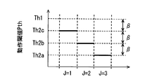
- FIG. 8 is a graph showing the relationship between the continuous detection number J and the operation threshold value Pth.
- the threshold values Th2a to Th2c all correspond to threshold values for cyclists.
- the operation threshold Pth is determined by a linear function having the continuous detection number J as a variable, but is not limited thereto. For example, it may be determined by a quadratic function using the continuous detection number J as a variable. Further, a table representing the correspondence relationship between the continuous detection number J and the operation threshold value Pth is stored in the flash memory, and the operation threshold value Pth corresponding to the continuous detection number J is determined by referring to the table. Good.
- the processing after determining the operation threshold value Pth as described above is the same as the processing after S7 shown in FIG. That is, the determined operation threshold value Pth is compared with the output value P, and the external protection device 5 is operated when the output value P is larger than the operation threshold value Pth. If the output value P is less than or equal to the operation threshold value Pth, the flow is terminated without operating the external protection device 5.
- the operation of the collision object identification unit 14 and the threshold value determination unit 15 when the collision object determination unit 14 determines that the collision object is a cyclist has been described above.
- the collision object is an object of another type.
- a threshold value corresponding to the continuous detection number J may be determined.
- the operation threshold value Pth corresponding to the type of the collision object is determined as in the first embodiment described above.
- the operation threshold Pth when the collision object is a cyclist is determined to be a value smaller than the pedestrian threshold Th1. Therefore, according to this 2nd Embodiment, the cyclist as a collision object can be protected more appropriately like 1st Embodiment.
- a general image recognition unit uses a specified number of frames of image data to determine the result of image recognition processing.
- the control device 1 cannot identify the type of the collision object, and cannot apply the operation threshold value Pth corresponding to the type of the collision object.
- the collision object is specified based on the image recognition result with respect to the latest frame photographed at (or immediately before) the collision occurrence time. Therefore, compared to the conventional configuration in which the image recognition processing result is determined using image data of a prescribed number of frames, the possibility that the operation threshold value Pth corresponding to the type of the collision object cannot be set is reduced. I can do things. For example, when a cyclist as a collision object can be photographed with only the latest frame, a value lower than the pedestrian threshold (that is, the cyclist threshold) can be applied as the motion threshold Pth.
- pre-crash safety system a system that automatically applies braking force to the host vehicle when there is a possibility of a collision.
- the pre-crash safety system is mounted on the host vehicle as described above, the pre-crash safety system is activated when the camera 3 has captured an object that is likely to collide with the host vehicle for more than the specified number of frames. Therefore, the possibility that the collision candidate collides with a cyclist or the like while the host vehicle is actually traveling is suppressed.
- the motion threshold value Pth is used for the pedestrian.
- a value lower than the threshold can be applied. That is, even if the host vehicle collides with a cyclist in a manner that cannot be handled by the pre-crash safety system, the cyclist as the collision object can be protected.
- the operation threshold value Pth is determined using not only the type of the collision object detected from the latest frame but also the continuous detection number J. This is due to the following reason. There is a possibility that the type of the collision object is erroneously recognized only by the result of the recognition process for the latest frame. However, if the detected object detected as a colliding object candidate in the latest frame can be detected continuously more than a certain number of times in the past frames, the type of the colliding object may be misrecognized. Is reduced. That is, as the number of consecutive detections J increases, the probability (that is, the reliability) of the identification result of the collision object type increases.
- the collision object is detected when the cyclist is detected as a collision object candidate in the latest two frames of image data, rather than when the cyclist is detected as a collision object candidate only in the latest one frame. This suggests that the possibility of being a cyclist is high.
- the continuous detection number J represents the reliability with respect to the specified result by the collision object specifying unit 14, similarly to the reliability introduced in the first embodiment. Therefore, according to the above configuration, as in the first embodiment, unnecessary operation of the external protection device 5 and inactivation of the external protection device 5 in a necessary scene can be suppressed.
- the reliability may be determined as a high level, and if the continuous detection number J is 1, it may be determined as a low level. Further, the reliability may be expressed as a specific numerical value instead of being expressed by a category such as a high level or a low level. For example, the reliability may be expressed as a function that increases as the number of consecutive detections J increases.
- the detection success rate is calculated as 66.7%. Then, the higher the detection success ratio, the closer the movement threshold Pth is to the first cyclist threshold Th2a, and the lower the detection success ratio is, the closer the movement threshold Pth is to the pedestrian threshold Th1. Even in such an aspect, the same effects as those of the second embodiment described above can be obtained.
- the protection device control system 100 does not include the millimeter wave radar 2 and the control device 1 also exemplifies a mode in which the detection result of the millimeter wave radar 2 is not acquired.
- the protection device control system 100 according to the second embodiment may include the millimeter wave radar 2, and the control device 1 may acquire a detection result from the millimeter wave radar 2. That is, the control device 1 includes the radar information acquisition unit 12, and the collision object specifying unit 14 and the threshold value determination unit 15 specify the collision object using the detection result of the millimeter wave radar 2 acquired by the radar information acquisition unit 12. Or an operating threshold value may be determined.
- the millimeter wave radar 2 detects a moving body other than a four-wheeled vehicle as a collision object candidate, and detects a moving body other than the four-wheeled vehicle (for example, a cyclist) from the latest frame by the image recognition unit 13. If it is, the collision object may be determined to be a cyclist. That is, if there is no contradiction between the detection result by the millimeter wave radar 2 and the recognition result for the latest frame by the image recognition unit 13, the result of the image recognition process may be adopted. Further, when there is a contradiction between the detection result by the millimeter wave radar 2 and the recognition result for the latest frame by the image recognition unit 13, the collision object may be processed as unknown (S3, NO in FIG. 3).
- the operation threshold value Pth may be corrected based on the detection result of the millimeter wave radar 2, which is determined based on the recognition result (for example, the continuous detection number J) of the image recognition unit 13. .
- the reliability for the specific result of the collision object is calculated by the same method as in the above-described embodiment, and when the reliability is high, the operation threshold Pth determined based on the continuous detection number J is set. Just adopt it.
- the motion threshold value Pth determined based on the continuous detection number J may be set to a value obtained by approaching the pedestrian threshold value Th1. For example, a value obtained by adding the motion threshold Pth determined based on the continuous detection number J and the pedestrian threshold Th1 and dividing the result by 2 may be determined as the final motion threshold Pth.
- an object of the same type (or similar) as the collision object detected by the image recognition unit 13 with respect to the latest frame is represented by the millimeter wave radar. 2 is detected, and the case where it is determined that the reliability level is low is the case where the millimeter wave radar 2 cannot detect the collision object detected by the image recognition unit 13 for the latest frame. do it.
- An object with a similar type here refers to an object with the same reception level of reflected waves or an object with the same size when the millimeter wave radar 2 identifies the type of the object.
Landscapes
- Engineering & Computer Science (AREA)
- Mechanical Engineering (AREA)
- Radar, Positioning & Navigation (AREA)
- Remote Sensing (AREA)
- Traffic Control Systems (AREA)
- Radar Systems Or Details Thereof (AREA)
Abstract
保護制御装置(Protection Control Apparatus)(1)は、車両で用いられ、衝突物特定部(14)と、閾値決定部(15)と、動作指示部(16)とを備える。衝突物特定部は、物体認識部が取得している情報に基づいて、車両と衝突する衝突物の種別を特定する。閾値決定部は、特定されている衝突物の種別に基づいて、動作閾値として採用する値を決定する。動作指示部は、衝突センサが出力する出力値と、衝突物を保護するための保護デバイスを作動させるための動作閾値とを比較して、出力値が動作閾値よりも大きい値となっている場合に保護デバイスを動作させる。閾値決定部は、衝突物は歩行者であると特定されている場合には、歩行者用閾値を動作閾値として採用し、衝突物は自転車であると特定されている場合には、歩行者用閾値よりも小さいサイクリスト用閾値を、動作閾値として採用する。
Description
本出願は、2015年5月19日に出願された日本出願番号2015-102040号に基づくもので、ここにその記載内容を援用する。
本開示は、車両と衝突する人間を保護するための保護装置の動作を制御する保護制御装置(Protection Control Apparatus)に関する。
従来、車両と衝突した歩行者の保護するための技術として、歩行者との1次衝突を検出した場合に、例えば車両の外面に展開されるエアバッグ等の保護装置を動作させることによって、車両と2次衝突する歩行者を保護する技術が知られている(例えば特許文献1)。なお、ここでの1次衝突とは、車両と歩行者等との最初の衝突を指し、2次衝突とは車両と1次衝突した物体(衝突物とする)が、車両側に倒れこむことによって生じる衝突を指す。
このような技術においては、1次衝突を検出するための衝突検出センサの出力値に対して、歩行者と接触したと判定するための閾値(歩行者用閾値とする)を予め設定しておき、衝突検出センサの出力値がその歩行者用閾値を超過した場合に、保護装置を動作させる。なお、車両と衝突した歩行者を保護するための保護装置としては、上述の外部に展開されるエアバッグの他に、ポップアップフードなどがある。
ところで、歩行者だけでなく、自転車の乗員もまた、車両との衝突時において保護すべき対象である。したがって、乗員が乗車した自転車と車両とが衝突した場合にも、前述の保護装置が動作するべきである。便宜上、自転車の乗員及びその自転車を含む移動体を、サイクリストと称する。
非特許文献1には、サイクリストが車両に衝突した場合の衝突態様と、歩行者が車両に衝突した場合の衝突態様の違いについて記載されている。
「自動車衝突時における自転車乗員の挙動・障害の有限要素解析」、山田英氏,伊藤大輔,水野幸治著、公益社団法人自動車技術会発行、学術講演会前刷集No.144-14、2014年10月22日発行
非特許文献1に開示されているように、サイクリストが車両に衝突した場合の衝突態様と、歩行者が車両に衝突した場合の衝突態様とは異なる。発明者の考えるに、例えば、車両が1次衝突した対象がサイクリストである場合には、衝突検出センサの出力値は歩行者と衝突した場合よりも小さい値となる場合がある。その結果、衝突検出センサの出力値が歩行者用閾値を超過している場合に保護装置を動作させる構成(すなわち従来構成)においては、衝突物がサイクリストである場合に、保護装置が動作しない場合が生じうると思われる。
本開示の目的とするところは、歩行者に加えて自転車の乗員をより適切に保護することができる保護制御装置を提供することにある。
その目的を達成するための本開示の一つの観点によれば、保護制御装置は、車両で用いられ、物体と車両との衝突を検知する衝突センサの出力値を取得する出力値取得部と、車両周辺に存在する物体についての情報を取得する物体認識部と、物体認識部が取得している情報に基づいて、車両と衝突する物体である衝突物の種別を特定する衝突物特定部と、衝突センサが出力する出力値と、衝突物を保護するための保護デバイスを作動させるための動作閾値とを比較して、出力値が動作閾値よりも大きい値となっている場合に保護デバイスを動作させる動作指示部と、衝突物特定部によって特定されている衝突物の種別に基づいて、動作閾値として採用する値を決定する閾値決定部と、を備える。閾値決定部は、衝突物特定部によって衝突物は歩行者であると特定されている場合には、歩行者用閾値を動作閾値として採用し、衝突物特定部によって衝突物は、自転車であると特定されている場合には、歩行者用閾値よりも小さいサイクリスト用閾値を、動作閾値として採用する。
以上の構成では、衝突物が自転車である場合には、歩行者用閾値よりも小さいサイクリスト用閾値を、保護デバイスを動作させるか否かの判定に用いられる動作閾値として採用する。したがって、以上の構成によれば、車両と自転車とが衝突した場合には、歩行者用閾値よりも小さい所定の閾値を用いて保護デバイスを動作させるか否かを判定するため、保護デバイスが動作しない可能性を抑制することができる。つまり、自転車の乗員をより適切に保護することができる。
本開示についての上記目的およびその他の目的、特徴や利点は、添付の図面を参照しながら下記の詳細な記述により、より明確になる。
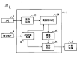
第1実施形態にかかる保護装置制御システムの概略的な構成の一例を示すブロック図である。
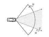
ミリ波レーダのレーダ検知エリア及びカメラの撮影範囲となる領域を示す模式図である。
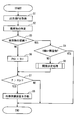
制御装置が実施する動作判定関連処理を説明するためのフローチャートである。
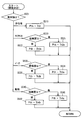
閾値決定部が実施する閾値決定処理を説明するためのフローチャートである。
第2実施形態にかかる保護装置制御システムの概略的な構成の一例を示すブロック図である。
第2実施形態における制御装置の作動を説明するための概念図である。
第2実施形態における制御装置が動作閾値を決定する処理を説明するためのフローチャートである。
図7に示すフローチャートの結果定まる動作閾値と連続検出数との関係を示すグラフである。
以下、本開示の実施形態について図を用いて説明する。図1は、本実施形態に係る保護装置制御システム100の概略的な構成の一例を示す図である。この保護装置制御システム100は、車両に搭載されている。便宜上、この保護装置制御システム100が搭載された車両は、自車両(ホスト車両)あるいはサブジェクト車両とも言及される。
この保護装置制御システム100は、自車両と衝突する人間を保護するためのシステムである。以降では、一例として自車両の前端部において種々の移動体と1次衝突する場合を想定した態様を例示するが、もちろん他の態様として、後端部や側部において種々の移動体と衝突する場合を想定したシステムであってもよく、その場合には、想定する衝突方向に応じて適宜変形して適用されればよい。
本実施形態における保護装置制御システム100は、図1に示すように、制御装置1(電子制御装置1とも言及される)、ミリ波レーダ2、カメラ3、衝突センサ4、及び外部保護装置5を備えている。制御装置1と、ミリ波レーダ2、カメラ3、衝突センサ4、及び外部保護装置5のそれぞれとは、車両内に構築された通信ネットワークを介して接続されている。制御装置1は、ミリ波レーダ2、カメラ3、及び衝突センサ4から提供されるデータに基づいて、自車両と衝突する人間を保護するための外部保護装置5の作動を制御する。この制御装置1は、保護制御装置とも言及される。制御装置1については、ミリ波レーダ2、カメラ3、衝突センサ4、及び外部保護装置5について述べた後に改めて説明する。
ミリ波レーダ2は、ミリ波又は準ミリ波を送受信することで、自車両前方の所定範囲(レーダ検知エリア21とする)に存在する物体についての情報を取得する。具体的には、レーダ検知エリア21内に存在する物体を検出するとともに、その検出した物体が存在する方向や距離、相対速度、種別等を推定する。ミリ波レーダ2の検出結果は、逐次、制御装置1に提供される。尚、情報は、不可算名詞のみならず、可算名詞としても使用される。複数の情報は、複数の情報項目と同等である。
検出物の種別は、その検出物に対応する反射波の受信レベル等に基づいて識別されればよい。ここでは、受信レベルが所定の第1閾値以上となっている場合には、検出物は四輪車両であると判定し、第1閾値未満であって且つ所定の第2閾値以上である場合には、四輪車両以外の移動体であると判定するものとする。第2閾値は、四輪車両以外の移動体とノイズとを区別するための閾値であり、第1閾値は、四輪車両以外の移動体と四輪車両とを識別するための閾値である。第1閾値、及び第2閾値は、適宜設計されればよい。ただし、第1閾値は第2閾値よりも高い値とする。
四輪以外の移動体とは、例えば歩行者や、自転車に乗車している乗員(つまりサイクリスト)、原動機付き自転車、二輪自動車等である。なお、ここでのサイクリストとは、自転車の乗員だけでなく、その乗員が乗車している自転車も含むものとする。検出物の種別の識別には、受信レベルの他、物体の大きさ、自車両の走行速度等の情報も用いても良い。例えば検出物が移動体か静止物かの識別に、自車両の相対速度を利用してもよい。
このミリ波レーダ2は、所望のレーダ検知エリア21を形成するように車両の適宜設計される位置に配置される。例えば、指向性の中心方向が自車両正面を向くように、フロントグリルやフロントバンパ等に設けられればよい。なお、本実施形態におけるミリ波レーダ2は、準ミリ波を送受信するものであって、その水平方向における指向角は45度、最大検出距離は車両前端から35mとする。レーダ検知エリア21は、ミリ波レーダ2の指向角や最大検出距離に応じた範囲となる。
なお、ここでは一例としてミリ波レーダ2が、レーダ検知エリア21に送信した準ミリ波の反射波の受信結果を解析することで、検出物が存在する方向や距離、相対速度、種別などを推定する態様とするが、これに限らない。他の態様として、ミリ波レーダ2は受信結果を制御装置1に提供し、制御装置1が、ミリ波レーダ2から提供される反射波の受信結果を解析することで、検出物が存在する方向や距離、相対速度、種別などを推定する態様としてもよい。
また、他の態様として、自車両前方に存在する物体を検出するレーダ装置として、ミリ波レーダ2に代えてレーザレーダを採用してもよい。さらに、ミリ波レーダ2とレーザレーダを併用してもよい。例えばレーザレーダを用いてレーダ検知エリア21に存在する物体の輪郭や大きさを相対的に精度よく検出できる場合には、検出物の種別をより細かく判定することが好ましい。例えば、検出物の輪郭や大きさから、周知のパターンマッチング処理によって、検出物が歩行者、サイクリスト、バイク、四輪車両の何れに該当するかを識別できることが好ましい。
カメラ3は、光学式のカメラであって、例えばCMOSカメラやCCDカメラ等を用いることができる。カメラ3は、図2に示す自車両前方の所定範囲(撮影範囲31とする)を撮影するように、ウインドシールド上端部近傍(例えばルームミラー付近)に設置されればよい。カメラ3が撮影した画像データは逐次制御装置1に提供される。
もちろん、カメラ3の設置位置は、ルームミラー付近に限らず、車両前方に対するドライバの視界を遮らない位置に取り付けられればよい。また、他の態様としてカメラ3は、赤外線カメラや近赤外線カメラなどであってもよい。さらに、カメラ3はステレオカメラであってもよい。
なお、ミリ波レーダ2もカメラ3も、自車両周辺(ここでは前方)に存在する物体を検出する装置として機能する。このように物体を検出する装置を便宜上、物体検出装置と称する。
衝突センサ4は、自車両の前端部と物体との衝突(1次衝突)を検出するためのセンサであり、車両のフロントバンパに設けられている。衝突センサ4は、衝突の衝撃の大きさに応じた値を出力する。衝突センサ4の出力値は制御装置1に入力される。この衝突センサ4は、例えばフロントバンパに配されたチューブ(或いはチャンバ)内の圧力を感知するための圧力センサを用いて実現されればよい。
もちろん、衝突センサ4は、圧力式のセンサに限らない。例えば、車両のボディに沿って配された光ファイバから出力される光量の変化に基づいて衝突を検知するタイプのものであってもよい。また、衝突センサ4として加速度センサを用いてもよい。
外部保護装置5は、自車両と衝突する人間を保護するための装置である。外部保護装置5としては、フード後方を瞬時に持ち上げるポップアップフードや、車両外部の所定領域に展開する外部エアバッグ等がある。外部エアバッグとしては、フロントピラーの前面を覆うように展開するピラーエアバッグや、フードの後部のデッキの外面に展開するデッキエアバッグなど、その展開領域に応じた様々なものがある。外部保護装置5は、制御装置1からの指示に基づいて動作する。外部保護装置5は保護デバイスとも言及される。
制御装置1は、ミリ波レーダ2、カメラ3、及び衝突センサ4から入力される種々の信号に基づいて、外部保護装置5を動作させるべきか否かを判定する。そして、動作させるべきであると判定した場合には、外部保護装置5を動作させる。この制御装置1は、本実施形態では、一例として、通常のコンピュータとして構成されており、CPUや、主記憶装置(いわゆるメモリ)としてのRAM、補助記憶装置(いわゆるストレージ)としてのフラッシュメモリ、I/O、及びこれらの構成を接続するバスラインなどを備えている。ストレージには、通常のコンピュータを本実施形態における制御装置1として機能させるためのプログラムが格納されている。
制御装置1は、上記プログラムを実行することで実現する機能ブロックとして、出力値取得部11、レーダ情報取得部12、画像認識部13、衝突物特定部14、閾値決定部15、及び動作判定部16を備える。なお、制御装置1が備える各機能ブロックは、一つあるいは複数のIC等によりハードウェア的に実現されてもよい。
出力値取得部11は、衝突センサ4の出力値Pを取得する。出力値取得部11が取得した出力値Pは、動作判定部16に提供される。また、衝突センサ4の出力値Pが、物体と衝突したか否かを判定するための衝突検出閾値以上となっている場合には、衝突が発生した旨を示す衝突検知信号を衝突物特定部14に提供する。ここで用いる衝突検出閾値は、車両の走行に伴う振動などの外乱と、衝突の発生とを切り分けるための閾値である。衝突検出閾値は、外部保護装置5動作させるための種々の閾値(後述)のうち、最も小さい閾値と同じかそれよりも小さい値とすればよい。
レーダ情報取得部12は、ミリ波レーダ2の検出結果、すなわち、レーダ検知エリア21内に存在する物体についての情報を取得する。レーダ情報取得部12が取得した検出結果は衝突物特定部14に提供される。
画像認識部13は、カメラ3から入力される画像データを解析し、検出対象として予め設定されている移動体の検出、及び、その種別を特定する。例えば画像認識部13は、画像データに対してエッジ検出などの公知の画像処理を行い、画像に含まれている全ての物体の輪郭を抽出する。そして、画像処理を施した画像データに対して、パターンマッチング処理を行うことによって、検出対象となっている移動体を検出するとともに、その移動体の種別を特定する。
検出対象とする移動体は、歩行者やサイクリスト、バイク、四輪車両、動物等とする。また、それに伴い、画像認識部13は、検出物が歩行者、サイクリスト、バイク、四輪車両、動物の何れに属するかも判定する。なお、ここでのバイクとは二輪自動車及び原動機付き自転車等といった、自転車以外の二輪車両を指すものとする。動物は、鹿や馬、牛等の人間以外の動物を指す。また、ここではより好ましい態様として画像認識部13は、電柱や看板、ガードレール等の構造物も検出するものとする。
画像データからこれらの検出対象とする移動体を検出するために用いられるデータ(画像認識用データとする)は、図示しない記憶媒体に格納されていればよい。画像認識用データとは、例えば検出対象とする移動体の種別の形状パターンを表すデータなどが該当する。
また、画像認識部13は、画像データ内における検出物の位置や大きさから、検出物と自車両との相対距離を推定する。さらに、一旦検出した移動体については、周知の物体追跡手法を援用して追尾する。これにより、複数の連続するフレーム間における位置や大きさの変化度合いから、検出物の相対的な移動方向や移動速度を推定する。仮にカメラ3がステレオカメラである場合には、それぞれの画像データ内における同一物体の位置の差に基づいて相対位置を推定してもよい。
ところで、一般的に、画像認識処理による物体の検出及び識別は、1フレームの画像データに基づいて確定されるのではなく、予め規定された複数の連続するフレーム(例えば3フレーム)の画像データを用いて確定される。本実施形態における画像認識部13もまた、そのような一般的な構成と同様に、予め規定された数のフレームの画像データを用いて物体の検出及び識別を行う。具体的には、規定フレーム数分の画像データから、解像度を高めた(超解像の)1つの画像データを生成し、その解像度が高められた画像データに対して画像認識処理を施すことで物体の検出や種別の識別を行う。
なお、他の態様として、画像認識部13は、規定フレーム数分の連続する画像データのそれぞれに対して画像認識処理を実施し、それらの処理結果に基づいて、認識結果を確定してもよい。すなわち、複数の連続する画像データのそれぞれに対する画像認識処理の結果の整合性を判定し、それらの処理結果が一致(略一致を含む)している場合に、認識結果(種別や位置等)を確定させてもよい。
画像認識部13による画像認識処理の結果は、衝突物特定部14に提供される。なお、レーダ情報取得部12及び画像認識部13は物体認識部とも言及される。
衝突物特定部14は、レーダ情報取得部12が取得しているミリ波レーダの検出結果と、画像認識部13の認識結果を相補的に用いることで、自車両前方の所定範囲(前方検知エリアとする)に存在する物体についての情報を取得する。具体的には、前方検知エリア内に存在する移動体の種別や、相対位置、相対速度などを取得する。
ここでの前方検知エリアとは、レーダ検知エリア21と撮影範囲31とを足しあわせた領域である。ミリ波レーダの検出結果と、画像認識部13の認識結果を相補的に用いる技術は、センサ・フュージョン技術として周知であるため、ここではその詳細な説明は省略する。なお、通常、検出物の種別の識別精度は、ミリ波レーダ2よりも、画像データを用いて識別を行う画像認識部13のほうが高くなる。したがって、衝突物特定部14は、移動体の種別としては、画像認識部13による認識結果を優先して採用する。
衝突物特定部14はさらに、出力値取得部11から衝突検知信号が入力された場合には、その時点(衝突発生時点とする)までに取得している検出物の情報から、自車両と衝突した物体(衝突物とする)を特定する。具体的には、前方検知エリアに存在する検出物のうち、衝突発生時点(又はその直前)において最も自車両に近い位置に存在している検出物が衝突物であると判定する。
ただし、最も自車両に近い位置に存在している物体の位置が、自車両から一定距離(例えば3m)以上離れている場合には、その検出物以外の物体と接触している可能性がある。したがって、最も自車両に近い位置に存在している検出物と自車両との距離が一定距離以上となっている場合には、衝突物は、ミリ波レーダ2やカメラ3で捕捉できていない別の物体であると判定する。この場合、衝突物特定部14は衝突物を認識できていないことを意味する。
なお、他の態様として衝突物特定部14は、検出物の相対位置と相対速度から、検知エリアに存在する検出物毎に、衝突する危険度を示す指標として、TTC(time to collision)を算出してもよい。そのような態様においては、衝突物特定部14は、出力値取得部11から衝突検知信号が入力された時点(又はその直前)において、TTCが所定の閾値以下であって、かつ、最も小さい値となっている検出物と衝突したと判定すればよい。また、衝突物の特定には、自車両の走行速度や操舵角などの情報を用いても良い。
さらに、衝突物特定部14は、より小さい機能ブロックとして、信頼度評価部141を備える。信頼度評価部141は、衝突物を特定した場合に、その特定結果の確からしさ(=信頼度)を評価する機能ブロックである。
本実施形態で一例として、信頼度評価部141は、衝突物を検出(又は捕捉)していた物体検出装置の組み合わせによって判断する。具体的には、カメラ3の画像データから衝突物を認識できている場合には、その特定結果に対する信頼度を高レベルと判定する。一方、カメラ3では衝突物を捕捉できておらず、ミリ波レーダ2のみで衝突物を検出できている場合には、その特定結果に対する信頼度は低レベルであると判定する。これは、前述の通り物体の種別の識別精度は、ミリ波レーダ2よりも画像認識部13のほうが高いためである。なお、ミリ波レーダ2でもカメラ3でも衝突物を捕捉できていない場合には、衝突物の種別は不明として扱えばよい。衝突物特定部14が特定した、衝突物についての情報(種別やその信頼度)は、閾値決定部15に提供される。
なお、他の態様として、画像認識部13が、検出物の輪郭形状と、予め用意されている形状パターンとの一致度合いを算出する場合には、その一致度合いに基づいて信頼度を評価してもよい。例えば、予め用意されている形状パターンの一致度合いが所定の基準レベル以上である場合には、信頼度を高レベルと判定し、基準レベル未満である場合には低レベルであると判定すればよい。
閾値決定部15は、衝突物特定部14から提供される衝突物についての情報に基づいて、外部保護装置5を動作させるべきか否かを判定するための閾値である動作閾値Pthを決定する。この閾値決定部15の詳細については別途後述する。決定した動作閾値Pthは、動作判定部16に提供される。閾値決定部15は、閾値選定部15とも言及される。
動作判定部16は、閾値決定部15から提供される動作閾値Pthと、出力値取得部11から提供される出力値Pに基づいて、外部保護装置5を動作させるべきか否かを判定する。そして、動作させるべきであると判定した場合には、外部保護装置5に対して、動作するように指示する動作指示信号を出力し、動作させる。この動作判定部16は動作指示部とも言及される。
<動作判定関連処理について>
次に、図3に示すフローチャートを用いて、制御装置1が実施する、外部保護装置5を動作させるか否かを判定するための一連の処理(動作判定関連処理とする)について説明する。この図3に示すフローチャートは、例えば、衝突センサ4から衝突検知閾値以上の出力値Pが出力された場合に開始されれば良い。なお、この動作判定関連処理とは独立して、自車両前方に存在する物体についての情報を収集する処理は行われている。
次に、図3に示すフローチャートを用いて、制御装置1が実施する、外部保護装置5を動作させるか否かを判定するための一連の処理(動作判定関連処理とする)について説明する。この図3に示すフローチャートは、例えば、衝突センサ4から衝突検知閾値以上の出力値Pが出力された場合に開始されれば良い。なお、この動作判定関連処理とは独立して、自車両前方に存在する物体についての情報を収集する処理は行われている。
記載されるフローチャートは、複数のセクション(あるいはステップと言及される)を含み、各セクションは、たとえば、S1と表現される。さらに、各セクションは、複数のサブセクションに分割されることができる、一方、複数のセクションが合わさって一つのセクションにすることも可能である。各セクションは、デバイス、モジュール、あるいは、固有名として、例えば、取得セクションは、取得デバイス、取得モジュール、オブテイナとして、言及されることができる。また、セクションは、(i)ハードウエアユニット(例えば、コンピュータ)と組み合わさったソフトウエアのセクションのみならず、(ii)ハードウエア(例えば、集積回路、配線論理回路)のセクションとして、関連する装置の機能を含みあるいは含まずに実現できる。さらに、ハードウエアのセクションは、マイクロコンピュータの内部に含まれることもできる。
まず、S1では出力値取得部11が、出力値Pを取得し、その出力値Pを動作判定部16に提供するとともに、衝突物特定部14に対して衝突検知信号を出力してS2に移る。
S2では衝突物特定部14が、レーダ情報取得部12が取得しているミリ波レーダ2の検出結果と画像認識部13による認識結果に基づき、衝突物の種別を特定する。このS2において衝突物の種別が特定できた場合には、S3がYESとなってS4に移る。また、S2において衝突物の種別が特定できなかった場合には、S3がNOとなってS6に移る。なお、S3がYESとなった場合には、衝突物特定部14は、その衝突物の種別と、その種別の特定結果に対して信頼度評価部141が評価した信頼度を含む衝突物情報を閾値決定部15に提供する。
S4では閾値決定部15が、衝突物特定部14によって特定されている衝突物が四輪車両及び構造物の何れか該当するか否かを判定する。衝突物が四輪車両又は構造物である場合にはS4がYESとなって本フローを終了する。すなわち、外部保護装置5を動作させない。これは、衝突物が四輪車両や構造物である場合には、外部保護装置5を動作させる必要がないためである。もちろん、自車両の乗員を保護するための装置(室内エアバッグ等)は、出力値Pに応じて適宜動作させればよい。
また、衝突物が四輪車両や構造物以外である場合にはS4がYESとなって、S5に移る。S5では閾値決定部15が、衝突物特定部14から提供される衝突物情報に基づいて、動作閾値Pthとして採用する値を決定する処理(閾値決定処理とする)を実施する。この閾値決定処理については別途図4を用いて説明する。このS5での閾値決定処理が完了すると、S7に移る。
S6では、閾値決定部15が、動作閾値Pthとして、歩行者と接触したと判定するための値(すなわち歩行者用閾値)Th1を採用し、S7に移る。歩行者用閾値Th1は、自車両の走行に伴う振動などに起因して衝突センサ4が出力する範囲の値よりも十分に高く、さらには、小動物やプラスチック製のコーン等との接触時に衝突センサ4から出力される出力値Pよりも十分に大きい値とすることが好ましい。この歩行者用閾値Th1は、種々の試験によって決定されればよい。歩行者用閾値Th1は制御装置1が備えるフラッシュメモリに予め登録されていれば良い。
S7では動作判定部16が、以上の処理によって決定されている動作閾値Pthと出力値Pとを比較して、外部保護装置5を動作させるべきか否かを判定する。すなわち、出力値Pが動作閾値Pthよりも大きい場合には、外部保護装置5を動作させるべきであると判定し(S7 YES)、S8に移る。一方、出力値Pが動作閾値Pth以下である場合には、外部保護装置5を動作させるべきではないと判定し(S7 NO)、本フローを終了する。すなわち、出力値Pが動作閾値Pth以下である場合には、外部保護装置5を動作させない。
S8では動作判定部16が、外部保護装置5に対して動作指示信号を出力し、動作させて本フローを終了する。したがって、外部保護装置5が動作する場合とは、出力値Pが、移動体の種別に応じて定まる動作閾値Pthよりも大きい場合である。
<閾値決定処理について>
次に、図4に示すフローチャートを用いて閾値決定部15が実施する閾値決定処理について説明する。この図4に示すフローチャートは、図3に示すフローチャートのS5に移った時に開始されればよい。
次に、図4に示すフローチャートを用いて閾値決定部15が実施する閾値決定処理について説明する。この図4に示すフローチャートは、図3に示すフローチャートのS5に移った時に開始されればよい。
まず、S501では衝突物特定部14から提供される衝突物情報に基づき、衝突物の種別を判定する。ここで、衝突物特定部14によって衝突物は歩行者であると判定されている場合にはS510に移る。また、衝突物がサイクリストであると判定されている場合にはS520に移る。衝突物がバイクであると判定されている場合にはS530に移る。衝突物が人間以外の動物であると判定されている場合にはS540に移る。
S510では、動作閾値Pthとして歩行者用閾値Th1を採用して、本閾値決定処理の呼び出し元である動作判定関連処理(図3)に戻る。
S520では、衝突物がサイクリストであるという特定結果に対する信頼度が、高レベルであるか低レベルであるかを判定する。信頼度が高レベルである場合にはS521に移り、動作閾値Pthとして、後述の第1サイクリスト用閾値Th2aを採用して、本閾値決定処理の呼び出し元に戻る。また、信頼度が低レベルである場合にはS522に移り、動作閾値Pthとして、第2サイクリスト用閾値Th2bを採用して、本閾値決定処理の呼び出し元に戻る。
ここで用いる第1サイクリスト用閾値Th2a、及び第2サイクリスト用閾値Th2bは、何れも歩行者用閾値Th1よりも小さい値とする。これは、衝突物がサイクリストである場合には、衝突物が歩行者である場合よりも衝突センサ4の出力値が小さい値となる場合があるためである。衝突物がサイクリストである場合の動作閾値Pthを、歩行者との接触を想定している場合よりも小さい値とすることにより、衝突物がサイクリストである場合であっても、外部保護装置5が動作する可能性を高めることができる。なお、以降では、第1サイクリスト用閾値Th2a、及び第2サイクリスト用閾値Th2bといった、衝突物がサイクリストである場合に動作閾値Pthとして採用する閾値をサイクリスト用閾値と称する。
ところで、歩行者の姿勢や向きによっては、実際には衝突物は歩行者であるにも関わらず、衝突物はサイクリストであると誤判定される場合も想定される。そこで、信頼度が低レベルである場合に用いる第2サイクリスト用閾値Th2bは、信頼度が高レベルである場合に採用する第1サイクリスト用閾値Th2aから、歩行者用閾値Th1に寄せた値とする。具体的には、第2サイクリスト用閾値Th2bは、第1サイクリスト用閾値Th2aよりも大きい値とし、歩行者用閾値Th1と、第1サイクリスト用閾値Th2a、第2サイクリスト用閾値Th2bは、Th1>Th2b>Th2aの関係を満たすものとする。これによって、物体の認識精度に応じて、外部保護装置5を動作させるべきか否かの判定を実施することができる。
S530では、衝突物がバイクであるという特定結果に対する信頼度が、高レベルであるか低レベルであるかを判定する。信頼度が高レベルである場合にはS531に移り、動作閾値Pthとして、第1バイク用閾値Th3aを採用して、本閾値決定処理の呼び出し元に戻る。また、信頼度が低レベルである場合にはS532に移り、動作閾値Pthとして、第2バイク用閾値Th3bを採用して、本閾値決定処理の呼び出し元に戻る。
一般的に、バイクは自転車よりも重いため、衝突物がバイクである場合には、衝突センサ4の出力値は、衝突物が歩行者である場合と同等かそれよりも大きい値となる。したがって、第1バイク用閾値Th3aは、歩行者用閾値Th1以上の値とすればよい。
しかし、実際の衝突物がサイクリストである場合であっても、自転車に積載した荷物や撮影方向等によって、衝突物はバイクであると誤認識されてしまう可能性がある。また、衝突物がサイクリストである場合には、衝突センサ4の出力値が相対的に小さい値とある場合がある。したがって、信頼度が低レベルである場合に採用する第2バイク用閾値は、第1バイク用閾値Th3aよりも小さい値とする。ここでは一例として、第2サイクリスト用閾値Th2bと同程度の値とする。
また、S540では、衝突物が動物であるという特定結果に対する信頼度が、高レベルであるか低レベルであるかを判定する。信頼度が高レベルである場合にはS541に移り、動作閾値Pthとして、第1動物用閾値Th4aを採用して、本閾値決定処理の呼び出し元に戻る。また、信頼度が低レベルである場合にはS542に移り、動作閾値Pthとして、第2動物用閾値Th4bを採用して、本閾値決定処理の呼び出し元に戻る。
基本的に、人間以外の動物(例えば鹿)は、外部保護装置5による保護の対象としない場合が多い。また、動物との衝突によって外部保護装置5が動作することは抑制させたいといった需要がある。そこで、信頼度が高レベルで衝突物は動物であると判定されている場合に用いる第1動物用閾値Th4aは、衝突センサ4がほとんど出力することがないような十分に大きい値(或いは上限値)とする。これにより、衝突物が動物である場合に外部保護装置5を動作させてしまう可能性を低減する。
一方、杖やカート式の歩行補助器具を利用している歩行者を、鹿などの大型の動物と誤認識してしまう可能性もある。したがって、衝突物が動物であるという判定の信頼度が低レベルである場合に用いる第2動物用閾値Th4bは、歩行者用閾値Th1と同程度の値とすることが好ましい。
なお、以上で述べた種々の閾値は、歩行者用閾値Th1と同様に、種々の試験によって設計され、予め制御装置1が備えるフラッシュメモリ等の不揮発性の記憶媒体に登録されていればよい。また、ここでは一例として種々の閾値は、Th4a>Th3a≧Th1=Th4b>Th2b=Th3b>Th2aの関係を満たすものとするが、これに限らない。サイクリスト用の閾値(Th2a、Th2b)が、少なくとも歩行者用閾値Th1よりも小さい値となっていればよい。
<第1実施形態のまとめ>
以上の構成では、制御装置1は、衝突センサ4から衝突検知閾値以上の出力値が入力された場合には、ミリ波レーダ2や画像認識部13が検出している自車両前方の物体についての情報に基づいて衝突物の種別を特定する。そして、閾値決定部15は、衝突物の種別及びその特定結果に対する信頼度に基づいて、外部保護装置5を動作させるための動作閾値Pthを決定する。動作判定部16は、衝突センサ4の出力値Pが動作閾値Pthを超過している場合に、外部保護装置5を動作させる。
以上の構成では、制御装置1は、衝突センサ4から衝突検知閾値以上の出力値が入力された場合には、ミリ波レーダ2や画像認識部13が検出している自車両前方の物体についての情報に基づいて衝突物の種別を特定する。そして、閾値決定部15は、衝突物の種別及びその特定結果に対する信頼度に基づいて、外部保護装置5を動作させるための動作閾値Pthを決定する。動作判定部16は、衝突センサ4の出力値Pが動作閾値Pthを超過している場合に、外部保護装置5を動作させる。
以上の構成によれば、移動体の種別やその特定結果に対する信頼度に応じた動作閾値Pthを用いて、外部保護装置5を動作させる。すなわち、以上の構成において、動作閾値Pthは、衝突物の種別毎の衝突センサ4の出力値の傾向の違いを鑑みた値となっている。したがって、以上の構成によれば、衝突物の種別に応じて外部保護装置5を動作させるべきか否かをより適切に判定し、外部保護装置5の不要な作動や、必要な場面における外部保護装置5の不作動を抑制することができる。
特に、本実施形態では、衝突物がサイクリストである場合に動作閾値Pthとして適用されるサイクリスト用閾値Th2a、Th2bは、何れも歩行者用閾値Th1よりも小さい値である。したがって、衝突物がサイクリストである場合に外部保護装置5が動作しない可能性を抑制できる。
また、歩行者用閾値Th1は、自車両の走行に伴う振動などに起因して衝突センサ4が出力する範囲の値とは十分なギャップを有する値である。以上の構成によれば、動作閾値Pthを歩行者用閾値Th1よりも小さいとする場合とは、衝突物がサイクリストの可能性があると判定されている場合のみであるため、車両の走行に伴う振動などに起因して外部保護装置5を誤作動させてしまう恐れも抑制できる。
さらに、以上の構成によれば、衝突物がサイクリストであると判定した場合であっても、その信頼度の高さに応じて、歩行者用閾値Th1からの下げ幅を異なる値とする。具体的には、信頼度が低レベルである場合の下げ幅は、信頼度が高レベルである場合の下げ幅よりも小さくする。これによって、動作閾値Pthを歩行者用閾値Th1よりも相対的に大きく低減して用いる場面を限定的にすることが出来、衝突物の誤認識に起因して外部保護装置5を誤作動させてしまう恐れを低減することができる。
ところで、参考構成として、衝突センサの出力値から、逆説的に衝突物の種別を特定する構成も考えられる。しかしながら、衝突時における衝突物の姿勢等によって、衝突センサの出力値は変化してしまうため、衝突センサの出力値から衝突物を特定することは困難と言える。本実施形態の構成によれば、ミリ波レーダ2や画像認識部13の認識結果に基づいて衝突物の種別を特定するため、より精度よく衝突物を特定することができる。
なお、以上では信頼度を高レベルと低レベルの2段階で評価する態様を例示したが、これに限らない。信頼度は3段階や4段階等、3以上の複数の段階で評価しても良い。
また、以上、本開示の実施形態を説明したが、本開示は上述の実施形態に限定されるものではなく、次の実施形態も本開示の技術的範囲に含まれ、さらに、下記以外にも要旨を逸脱しない範囲内で種々変更して実施することができる。
[第2実施形態]
次に本開示の第2実施形態について、図を用いて説明する。なお、以降において前述の第1実施形態の構成の部材と同一の機能を有する部材については、同一の符号を付し、その説明を省略する。また、構成の一部のみに言及している場合、他の部分については先に説明した第1実施形態を適用することができる。
次に本開示の第2実施形態について、図を用いて説明する。なお、以降において前述の第1実施形態の構成の部材と同一の機能を有する部材については、同一の符号を付し、その説明を省略する。また、構成の一部のみに言及している場合、他の部分については先に説明した第1実施形態を適用することができる。
第2実施形態における保護装置制御システム100は、図5に示すように制御装置1、カメラ3、衝突センサ4、及び外部保護装置5を備え、制御装置1は、ミリ波レーダ2、カメラ3、衝突センサ4、及び外部保護装置5のそれぞれとは、車両内に構築された通信ネットワークを介して接続されている。
第1実施形態と第2実施形態との主たる相違点は、動作閾値Pthの決定方法にある。以下、この相違点に関連する部分を中心に、第2実施形態における制御装置1の構成及び作動について説明する。
本実施形態における画像認識部13は、1フレーム毎の画像データに対して画像認識処理を実施し、その結果を衝突物特定部14に提供する。すなわち、前述の第1実施形態では、規定された数のフレームの画像データを用いて画像認識処理の結果を確定し、その結果を衝突物特定部14に提供していたが、本実施形態では1フレーム毎の認識結果を衝突物特定部14に提供する。なお、他の態様として、1フレーム毎の認識結果と、規定された数のフレームの画像データを用いて確定された認識処理の結果の両方を逐次衝突物特定部14に提供してもよい。
また、衝突物特定部14は、図6に示すように画像認識部13から提供されるフレーム毎の認識結果を、新しいものから一定数分(例えば10フレーム分)メモリに保持する。そして、出力値取得部11から衝突検知信号が入力された場合には、その衝突検知信号が入力された時点(すなわち衝突発生時点)における最新フレームの認識結果に基づいて、衝突物を特定する。具体的には、最新フレームから衝突物候補として検出されている物体を衝突物と見なす。衝突物候補とは、自車両と接触する可能性が高い物体であり、ここでは一例として、自車両から一定距離(例えば3メートル)以内であって、最も自車両との距離が近い物体とする。
また、衝突物特定部14は、衝突物を特定すると、メモリに保持しているフレーム毎の画像認識処理の結果を、新しいものから順番に遡っていき、最新フレームで衝突部物候補として検出されている物体と同一の物体を、衝突物候補として検出できているフレームの数(連続検出数)を特定する。そして、閾値決定部15は、衝突物の種別と連続検出数に応じた動作閾値Pthを決定する。
図6は、画像認識部13、衝突物特定部14、及び閾値決定部15の動作を説明するための概念図である。図6は、最新のフレームと、最新のフレームよりも1つ前のフレームからは、衝突物候補としてサイクリストが検出されていることを示しており、最新のフレームよりも2つ前のフレームからは、衝突物候補に相当する物体が検出されていないことを示している。
このような場合、衝突物特定部14は、最新フレームに対する認識処理の結果に基づいて、衝突物はサイクリストであると判定する。また、衝突物候補としてサイクリストを検出できているフレームの数は2であるため、連続検出数は2と判定する。そして、閾値決定部15は、衝突物の種別がサイクリストであることと、連続検出数に応じた動作閾値Pthを決定する。
ここで、一例として最新フレームに対する認識結果に基づいて衝突物特定部14が衝突物はサイクリストであると判定した場合の、衝突物特定部14及び閾値決定部15の作動について、図7に示すフローチャートを用いて説明する。なお、衝突物特定部14による衝突物の特定は、たとえば図3に示すS2のタイミングで実施されればよい。また、図7に示すフローチャートは、S501において衝突物がサイクリストであると判定されている場合に開始されれば良い。つまり、図7に示すフローチャートは、図4に示すS520~522の代わりの処理に相当する。
まず、S1501では衝突物特定部14が、処理上に用いるパラメータとしての整数N、Jをそれぞれ1に設定してS1502に移る。Nは、最新フレームから何番目のフレームに対する画像認識処理の結果を参照するかを表す番号(参照フレーム番号とする)である。なお、参照フレーム番号は最新フレームを0番目のフレームとしてカウントするものとする。また、Jは、連続検出数を表すパラメータである。本フローの開始された時点において、既に最新フレームにサイクリストが検出されているため、S1501の時点で連続検出数Jは1とする。
S1502では衝突物特定部14が、最新フレームからN番目のフレームに対する画像認識処理の結果を参照し、衝突物候補としてサイクリストが検出されているか否かを判定する。ここで、衝突物候補としてサイクリストが検出されている場合には、S1503がYESとなってS1504に移る。一方、衝突物候補としてサイクリストが検出されているか否かを判定する。ここで、衝突物候補としてサイクリストが検出されていない場合には、S1503がNOとなってS1507に移る。
S1504では、連続検出数Jに1を加算することで、連続検出数Jを更新し、S1505に移る。S1505では、参照フレーム番号NがM-1未満であるか否かを判定する。ここで用いるMは、複数の連続するフレームを用いて画像認識処理の結果を確定させる場合に用いるフレームの数(つまり規定フレーム数)である。規定フレーム数Mは適宜設計されれば良いが、ここでは一例として3とする。
したがって、参照フレーム番号Nが1の場合にはS1505がYESとなってS1506に移り、参照フレーム番号N=2となっている場合には、S1505がNOとなってS1507に移る。参照フレーム番号N=2となっている場合とは、最新フレームと、最新フレームから1つ前のフレームと、最新フレームから2つ前のフレームの、計3つのフレームに対する画像認識処理の結果を参照した状態であることを意味している。
S1506では、Nに1を加算することで、参照フレーム番号としてのNを更新し、S1502に戻る。
S1507では、連続検出数Jに応じた動作閾値Pthを決定する。ここでは一例として、次に式によってPthの値を決定するものとする。
(式1) Pth=Th1-β×J
上記式1で用いるTh1は前述の歩行者用閾値であり、βは適宜設計される正の定数である。βは歩行者用閾値Th1と第1サイクリスト用閾値Th2aの差の絶対値を3で割った値とする。この式1によれば、連続検出数Jが多いほど動作閾値Pthは小さくなり、J=3の場合、動作閾値Pthは、第1サイクリスト用閾値Th2aと等しくなる。便宜上、J=1の時の値をTh2c、J=2の時の値をTh2bとする。図8は、連続検出数Jと動作閾値Pthの関係は示すグラフである。閾値Th2a~Th2cは何れもサイクリスト用閾値に相当する。
(式1) Pth=Th1-β×J
上記式1で用いるTh1は前述の歩行者用閾値であり、βは適宜設計される正の定数である。βは歩行者用閾値Th1と第1サイクリスト用閾値Th2aの差の絶対値を3で割った値とする。この式1によれば、連続検出数Jが多いほど動作閾値Pthは小さくなり、J=3の場合、動作閾値Pthは、第1サイクリスト用閾値Th2aと等しくなる。便宜上、J=1の時の値をTh2c、J=2の時の値をTh2bとする。図8は、連続検出数Jと動作閾値Pthの関係は示すグラフである。閾値Th2a~Th2cは何れもサイクリスト用閾値に相当する。
なお、ここでは動作閾値Pthを、連続検出数Jを変数とする1次関数によって決定する態様とするがこれに限らない。例えば、連続検出数Jを変数とする2次関数等によって決定してもよい。さらに、連続検出数Jと動作閾値Pthとの対応関係を表すテーブルをフラッシュメモリに格納しておき、当該テーブルを参照することで、連続検出数Jに対応する動作閾値Pthを決定する態様としてもよい。
以上のようにして、動作閾値Pthを決定した後の処理は、図3に示すS7以降の処理と同様である。すなわち、決定した動作閾値Pthと出力値Pとを比較して、出力値Pが動作閾値Pthよりも大きい場合に、外部保護装置5を動作させる。また、出力値Pが動作閾値Pth以下である場合には、外部保護装置5を動作させずにフローを終了する。
なお、以上では一例として、衝突物特定部14が衝突物はサイクリストであると判定した場合の、衝突物特定部14及び閾値決定部15の作動について説明したが、衝突物が他の種別の物体(バイクや動物)である場合も同様に、連続検出数Jに応じた閾値を決定すればよい。
<第2実施形態のまとめ>
以上の構成では、先に説明した第1実施形態と同様に、衝突物の種別に応じた動作閾値Pthを決定する。特に、衝突物がサイクリストである場合の動作閾値Pthは、歩行者用閾値Th1よりも小さい値に決定する。したがって、この第2実施形態によれば、第1実施形態と同様に、衝突物としてのサイクリストをより適切に保護することができる。
以上の構成では、先に説明した第1実施形態と同様に、衝突物の種別に応じた動作閾値Pthを決定する。特に、衝突物がサイクリストである場合の動作閾値Pthは、歩行者用閾値Th1よりも小さい値に決定する。したがって、この第2実施形態によれば、第1実施形態と同様に、衝突物としてのサイクリストをより適切に保護することができる。
また、一般的な画像認識部は、規定された数のフレームの画像データを用いて画像認識処理の結果を確定させている。しかしながら、移動体がカメラの撮影範囲の外から自車両の前方に急に飛び出てきて衝突した場合には、当該衝突物としての移動体を捕捉したフレームの数が、規定フレーム数未満となってしまう可能性がある。そのような場合には、制御装置1は、衝突物の種別を特定する事ができず、衝突物の種別に応じた動作閾値Pthの適用も実施できなくなってしまう。
一方、本実施形態の構成によれば、衝突発生時点(又はその直前)に撮影された最新フレームに対する画像認識結果に基づいて衝突物を特定する。したがって、規定された数のフレームの画像データを用いて画像認識処理の結果を確定させる従来の構成に比べて、衝突物の種別に応じた動作閾値Pthの設定ができなくなってしまう恐れを低減する事ができる。例えば、最新フレームだけでも衝突物としてのサイクリストを撮影することができている場合には、動作閾値Pthとして、歩行者用閾値よりも低い値(つまりサイクリスト用閾値)を適用する事ができる。
特に、近年は衝突の可能性がある場合には自動的に自車両に制動力を付与するシステム(いわゆるプリクラッシュセーフティシステム)を搭載した車両が普及してきている。そのように自車両にプリクラッシュセーフティシステムが搭載されているものとした場合、カメラ3が規定フレーム数以上、自車両と衝突しそうな物体を捕捉出来ている場合にはプリクラッシュセーフティシステムが作動するため、実際に自車両が走行している状態で当該衝突候補物がサイクリスト等の衝突する可能性は抑制される。
すなわち、プリクラッシュセーフティシステムが搭載されているにも関わらず、自車両と移動体(例えばサイクリスト)とが衝突してしまう場合とは、衝突物を規定フレーム数以上撮影出来ていない可能性が高い。
そのような事情に対して、上述したように本実施形態の構成によれば、最新フレームだけでも衝突物としてのサイクリストを撮影することができている場合には、動作閾値Pthとして、歩行者用閾値よりも低い値を適用できる。つまり、プリクラッシュセーフティシステムで対応できないような態様で、自車両がサイクリストと衝突した場合であっても、当該衝突物としてのサイクリストを保護することができる。
また、以上の構成では、最新フレームから検出された衝突物の種別だけでなく、連続検出数Jも用いて動作閾値Pthを決定する。これは、次の理由による。最新フレームに対する認識処理の結果だけでは、衝突物の種別を誤って認識している可能性がある。しかし、最新フレームにおいて衝突物候補として検出されている検出物を、それよりも過去のフレームにおいて一定回数以上連続して検出できている場合には、その衝突物の種別を誤認識している恐れは低減される。つまり、連続検出数Jが多いほど、衝突物の種別の特定結果に対する確からしさ(すなわち信頼度)を高まっていく。
例えば、最新の1フレームにおいてのみ、サイクリストを衝突物候補として検出している場合よりも、直近の2フレーム分の画像データにおいて、サイクリストを衝突物候補として検出している場合のほうが、衝突物がサイクリストである可能性は高いことを示唆している。
また、最新の3フレームの何れにおいても同一の検出物(例えばサイクリスト)を衝突物候補として検出している場合、従来の一般的な構成と同様に、十分に信頼性を有する認識結果であることを示唆している。
すなわち、連続検出数Jは先の第1実施形態で導入していた信頼度と同様に、衝突物特定部14による特定結果に対する信頼度を表すものである。したがって、以上の構成によれば、第1実施形態と同様に、外部保護装置5の不要な作動や、必要な場面における外部保護装置5の不作動を抑制することができる。
[変形例1]
第2実施形態では、連続検出数Jから動作閾値Pthを決定する態様を例示したが、これに限らない。連続検出数Jから信頼度を評価し、その信頼度に基づいて第1実施形態と同様に動作閾値Pthを決定してもよい。
第2実施形態では、連続検出数Jから動作閾値Pthを決定する態様を例示したが、これに限らない。連続検出数Jから信頼度を評価し、その信頼度に基づいて第1実施形態と同様に動作閾値Pthを決定してもよい。
例えば連続検出数Jが2以上なら信頼度を高レベル、連続検出数Jが1なら低レベルと判定すればよい。また、信頼度は、高レベルや低レベルといった区分によって表されるのではなく、具体的な数値として表されても良い。例えば信頼度は、連続検出数Jが多いほど高くなる関数で表してもよい。
[変形例2]
第2実施形態では、連続検出数Jによって動作閾値Pthを決定する態様を例示したが、これに限らない。過去の規定フレーム数分のフレームのうち、最新フレームの認識結果から衝突物と判定された物体と同一の物体を衝突物候補として検出できているフレームの比率(検出成功比率とする)に基づいて、動作閾値Pthを算出してもよい。
第2実施形態では、連続検出数Jによって動作閾値Pthを決定する態様を例示したが、これに限らない。過去の規定フレーム数分のフレームのうち、最新フレームの認識結果から衝突物と判定された物体と同一の物体を衝突物候補として検出できているフレームの比率(検出成功比率とする)に基づいて、動作閾値Pthを算出してもよい。
例えば、3フレーム中、衝突物としてのサイクリストを検出できているフレームの数が2フレームである場合には、検出成功比率を66.7%と算出する。そして、検出成功比率が高いほど、動作閾値Pthを第1サイクリスト用閾値Th2aに近づけ、検出成功比率が低いほど、動作閾値Pthを歩行者用閾値Th1に近づければよい。このような態様によっても、上述した第2実施形態と同様の効果を奏する。
[変形例3]
第2実施形態では、保護装置制御システム100はミリ波レーダ2を備えず、制御装置1もまた、ミリ波レーダ2の検出結果を取得しない態様を例示したが、これに限らない。第2実施形態における保護装置制御システム100はミリ波レーダ2を備え、制御装置1はミリ波レーダ2からの検出結果を取得する態様としてもよい。すなわち、制御装置1がレーダ情報取得部12を備えるとともに、衝突物特定部14や閾値決定部15は、レーダ情報取得部12が取得するミリ波レーダ2の検出結果を用いて、衝突物を特定したり、動作閾値を決定したりしてもよい。
第2実施形態では、保護装置制御システム100はミリ波レーダ2を備えず、制御装置1もまた、ミリ波レーダ2の検出結果を取得しない態様を例示したが、これに限らない。第2実施形態における保護装置制御システム100はミリ波レーダ2を備え、制御装置1はミリ波レーダ2からの検出結果を取得する態様としてもよい。すなわち、制御装置1がレーダ情報取得部12を備えるとともに、衝突物特定部14や閾値決定部15は、レーダ情報取得部12が取得するミリ波レーダ2の検出結果を用いて、衝突物を特定したり、動作閾値を決定したりしてもよい。
例えば、ミリ波レーダ2で衝突物の候補として四輪車両以外の移動体を検出してあって、画像認識部13による最新フレームからも四輪車両以外の移動体(例えばサイクリスト)を検出している場合には、衝突物はサイクリストであると判定すればよい。つまり、ミリ波レーダ2による検出結果と画像認識部13による最新フレームに対する認識結果に矛盾が生じなければ、その画像認識処理の結果を採用する態様とすればよい。また、ミリ波レーダ2による検出結果と画像認識部13による最新フレームに対する認識結果に矛盾が生じた場合には、衝突物は不明として処理すればよい(図3 S3 NO)。
また、動作閾値Pthは、上述したように画像認識部13の認識結果(例えば連続検出数J)に基づいて決定した動作閾値Pthを、ミリ波レーダ2の検出結果に基づいて補正してもよい。具体的には、前述の実施形態と同様の方法によって衝突物の特定結果に対する信頼度を算出し、信頼度が高レベルである場合には、連続検出数Jに基づいて決定した動作閾値Pthをそのまま採用すればよい。一方、信頼度が低レベルである場合には、連続検出数Jに基づいて決定した動作閾値Pthを歩行者用閾値Th1に寄せた値とすればよい。例えば、連続検出数Jに基づいて決定した動作閾値Pthと歩行者用閾値Th1とを足して2で割った値を最終的な動作閾値Pthとして決定すればよい。
なお、この変形例3において、信頼度が高レベルであると判定する場合とは、最新フレームに対して画像認識部13が検出した衝突物と同じ(又は類似する)種別の物体をミリ波レーダ2が検出している場合であり、信頼度が低レベルであると判定する場合とは、最新フレームに対して画像認識部13が検出した衝突物をミリ波レーダ2が検出できていない場合とすればよい。ここでの種別が類似する物体とは、ミリ波レーダ2が物体の種別を識別する上で、反射波の受信レベルが同程度となる物体や、大きさが同程度となる物体を指す。
[変形例4]
以上で述べた第1実施形態、第2実施形態において、衝突物の種別を、衝突発生時点、又はその直前に取得したミリ波レーダ2の検出結果や画像データに基づいて特定する態様を例示したがこれに限らない。少なくとも衝突発生時点及びその直前の少なくとも何れかの情報を利用して衝突物を特定すればよい。例えば、衝突発生時点及びその直前に取得した情報に加えて、衝突発生直後において取得した情報も併用して、衝突物を特定してもよい。
以上で述べた第1実施形態、第2実施形態において、衝突物の種別を、衝突発生時点、又はその直前に取得したミリ波レーダ2の検出結果や画像データに基づいて特定する態様を例示したがこれに限らない。少なくとも衝突発生時点及びその直前の少なくとも何れかの情報を利用して衝突物を特定すればよい。例えば、衝突発生時点及びその直前に取得した情報に加えて、衝突発生直後において取得した情報も併用して、衝突物を特定してもよい。
本開示は、実施例に準拠して記述されたが、本開示は当該実施例や構造に限定されるものではないと理解される。本開示は、様々な変形例や均等範囲内の変形をも包含する。加えて、様々な組み合わせや形態、さらには、それらに一要素のみ、それ以上、あるいはそれ以下、を含む他の組み合わせや形態をも、本開示の範疇や思想範囲に入るものである。
Claims (11)
- 車両で用いられ、
物体と前記車両との衝突を検知する衝突センサの出力値を取得する出力値取得部(11)と、
前記車両周辺に存在する物体についての情報を取得する物体認識部(12、13)と、
前記物体認識部が取得している情報に基づいて、前記車両と衝突する前記物体である衝突物の種別を特定する衝突物特定部(14)と、
前記衝突センサが出力する出力値と、衝突物を保護するための保護デバイスを作動させるための動作閾値とを比較して、前記出力値が前記動作閾値よりも大きい値となっている場合に前記保護デバイスを動作させる動作指示部(16)と、
前記衝突物特定部によって特定されている前記衝突物の種別に基づいて、前記動作閾値として採用する値を決定する閾値決定部(15)と、を備え、
前記閾値決定部は、
前記衝突物特定部によって前記衝突物は歩行者であると特定されている場合には、歩行者用閾値を前記動作閾値として採用し、
前記衝突物特定部によって前記衝突物は自転車であると特定されている場合には、前記歩行者用閾値よりも小さいサイクリスト用閾値を、前記動作閾値として採用する
保護制御装置。 - 請求項1において、
前記閾値決定部は、前記衝突物特定部によって特定されている前記衝突物の種別と、前記衝突物特定部の特定結果に対する信頼度に基づいて、前記動作閾値を決定する
保護制御装置。 - 請求項2において、
前記サイクリスト用閾値として、複数段階の値が設定されてあって、
前記閾値決定部は、前記衝突物特定部によって前記衝突物は自転車であると特定されている場合には、その特定結果に対する信頼度が高いほど、複数段階の前記サイクリスト用閾値のうち、より小さい前記サイクリスト用閾値を前記動作閾値として採用する
保護制御装置。 - 請求項3において、
前記サイクリスト用閾値として、所定の第1サイクリスト用閾値と、前記第1サイクリスト用閾値よりも大きく、かつ、前記歩行者用閾値よりも小さい第2サイクリスト用閾値が設定されてあって、
前記物体認識部として、
前記車両に設けられているレーダ装置の検出結果に基づいて、前記車両周辺に存在する前記物体についての情報を取得するレーダ情報取得部と、
前記車両周辺の所定範囲を撮影するカメラの撮影画像に対して画像認識処理を実施することで、車両周辺に存在する前記物体についての情報を取得する画像認識部と、を備え、
前記閾値決定部は、
前記画像認識部によって前記衝突物としての自転車を認識できている場合には、前記第1サイクリスト用閾値を前記動作閾値として採用し、
前記画像認識部によって前記衝突物としての自転車を認識できておらず、かつ、前記レーダ情報取得部が取得している情報に基づいて前記衝突物特定部によって前記衝突物は自転車であると特定されている場合には、前記第2サイクリスト用閾値を前記動作閾値として採用する
保護制御装置。 - 請求項3において、
前記物体認識部として、
前記車両周辺の所定範囲を撮影するカメラの撮影画像に対して画像認識処理を実施することで、前記車両周辺に存在する前記物体についての情報を取得する画像認識部を備え、
前記サイクリスト用閾値として、複数段階の値が設定されてあって、
前記閾値決定部は、前記衝突物としての前記自転車を認識できているフレームの数が多いほど、複数段階の前記サイクリスト用閾値のうち、より小さい値となっている前記サイクリスト用閾値を前記動作閾値として採用する一方、前記衝突物としての前記自転車を認識できているフレーム数が少ないほど、複数段階の前記サイクリスト用閾値のうち、より大きい値となっている前記サイクリスト用閾値を前記動作閾値として採用する
保護制御装置。 - 請求項2から5の何れか1項において、
前記衝突物特定部による特定結果の信頼度を評価する信頼度評価部(141)を備え、
前記物体認識部として、
前記車両に設けられているレーダ装置の検出結果に基づいて、前記車両周辺に存在する前記物体についての情報を取得するレーダ情報取得部と、
前記車両周辺の所定範囲を撮影するカメラの撮影画像に対して画像認識処理を実施することで、前記車両周辺に存在する前記物体についての情報を取得する画像認識部と、を備え、
前記信頼度評価部は、
前記画像認識部が前記衝突物に相当する物体を認識できている場合には、信頼度を高く評価し、
前記画像認識部が前記衝突物についての情報を取得できておらず、前記レーダ情報取得部が取得している情報に基づいて前記衝突物特定部が前記衝突物を特定している場合には、信頼度を低く評価する
保護制御装置。 - 請求項2から5の何れか1項において、
前記衝突物特定部による特定結果の信頼度を評価する信頼度評価部(141)を備え、
前記物体認識部として、
前記車両周辺の所定範囲を撮影するカメラの撮影画像に対して画像認識処理を実施することで、前記車両周辺に存在する前記物体についての情報を取得する画像認識部を備え、
前記信頼度評価部は、
前記衝突物を認識できているフレーム数が多いほど信頼度を高く評価する
保護制御装置。 - 請求項2から7の何れか1項において、
前記閾値決定部は、前記衝突物特定部によって前記衝突物は動物であると特定されてあって、かつ、その特定結果に対する信頼度が低い場合には、前記動作閾値として前記歩行者用閾値を採用する
保護制御装置。 - 請求項2から8の何れか1項において、
前記動作指示部は、前記衝突物特定部によって前記衝突物は動物であると特定されてあって、かつ、その特定結果に対する信頼度が高い場合には、前記保護デバイスを動作させない
保護制御装置。 - 請求項1から9の何れか1項において、
前記閾値決定部は、前記衝突物特定部によって前記衝突物はバイクであると特定されている場合には、前記歩行者用閾値と同じかそれ以上の値となるように予め定められているバイク用閾値を、前記動作閾値として採用する
保護制御装置。 - 請求項1から10の何れか1項において、
前記動作指示部は、前記衝突物特定部によって前記衝突物は四輪車両であると特定されている場合には、前記保護デバイスを動作させない
保護制御装置。
Priority Applications (1)
| Application Number | Priority Date | Filing Date | Title |
|---|---|---|---|
| DE112016002257.3T DE112016002257B4 (de) | 2015-05-19 | 2016-03-29 | Schutzsteuerungsvorrichtung |
Applications Claiming Priority (2)
| Application Number | Priority Date | Filing Date | Title |
|---|---|---|---|
| JP2015102040A JP6337834B2 (ja) | 2015-05-19 | 2015-05-19 | 保護制御装置 |
| JP2015-102040 | 2015-05-19 |
Publications (1)
| Publication Number | Publication Date |
|---|---|
| WO2016185653A1 true WO2016185653A1 (ja) | 2016-11-24 |
Family
ID=57319731
Family Applications (1)
| Application Number | Title | Priority Date | Filing Date |
|---|---|---|---|
| PCT/JP2016/001818 Ceased WO2016185653A1 (ja) | 2015-05-19 | 2016-03-29 | 保護制御装置 |
Country Status (3)
| Country | Link |
|---|---|
| JP (1) | JP6337834B2 (ja) |
| DE (1) | DE112016002257B4 (ja) |
| WO (1) | WO2016185653A1 (ja) |
Cited By (4)
| Publication number | Priority date | Publication date | Assignee | Title |
|---|---|---|---|---|
| US20200377053A1 (en) * | 2019-05-31 | 2020-12-03 | Honda Motor Co., Ltd. | Vehicle-use object protection device |
| US20210323548A1 (en) * | 2020-04-20 | 2021-10-21 | Subaru Corporation | Surrounding moving object detector |
| CN115082877A (zh) * | 2021-03-16 | 2022-09-20 | 丰田自动车株式会社 | 图像处理装置、图像处理方法和非暂时性存储介质 |
| CN115092091A (zh) * | 2022-07-11 | 2022-09-23 | 中国第一汽车股份有限公司 | 一种基于车联网的车辆行人保护系统及方法 |
Families Citing this family (15)
| Publication number | Priority date | Publication date | Assignee | Title |
|---|---|---|---|---|
| JP6539435B2 (ja) | 2013-11-29 | 2019-07-03 | レオン自動機株式会社 | 食品生地の丸め成形装置及び丸め成形方法 |
| JP6565653B2 (ja) * | 2015-12-11 | 2019-08-28 | トヨタ自動車株式会社 | 車両用衝突対象保護装置 |
| JP6690601B2 (ja) * | 2017-06-07 | 2020-04-28 | 株式会社デンソー | 保護制御装置 |
| JP6806017B2 (ja) | 2017-09-25 | 2020-12-23 | 株式会社デンソー | 保護制御装置 |
| JP6806018B2 (ja) | 2017-09-25 | 2020-12-23 | 株式会社デンソー | 保護制御装置及び保護システム |
| JP6794972B2 (ja) | 2017-10-30 | 2020-12-02 | 株式会社デンソー | 保護制御装置 |
| JP6825539B2 (ja) * | 2017-10-30 | 2021-02-03 | 株式会社デンソー | 保護制御装置 |
| KR102628282B1 (ko) * | 2018-10-10 | 2024-01-24 | 현대자동차주식회사 | 차량 및 그 제어 방법 |
| JP7196759B2 (ja) | 2019-05-10 | 2022-12-27 | 株式会社デンソー | 保護デバイス制御装置 |
| KR20220028098A (ko) * | 2019-07-04 | 2022-03-08 | 넥스트나브, 엘엘씨 | 결정된 컨텍스트의 신뢰성을 개선하기 위해 모바일 디바이스의 압력 센서를 사용하기 위한 시스템 및 방법 |
| JP2021071780A (ja) * | 2019-10-29 | 2021-05-06 | 大日本印刷株式会社 | 情報処理装置、情報処理方法及びプログラム |
| JP7658746B2 (ja) * | 2020-04-20 | 2025-04-08 | 株式会社Subaru | 車両周辺移動体検知装置 |
| KR102877570B1 (ko) * | 2020-10-06 | 2025-10-29 | 현대자동차주식회사 | 차량 및 그 제어방법 |
| JP7723540B2 (ja) * | 2020-12-08 | 2025-08-14 | 株式会社東芝 | 解析システム、解析方法、および解析プログラム |
| JP7503038B2 (ja) * | 2021-10-29 | 2024-06-19 | Kddi株式会社 | 情報処理装置、情報処理方法及びコンピュータプログラム |
Citations (7)
| Publication number | Priority date | Publication date | Assignee | Title |
|---|---|---|---|---|
| JPH10119713A (ja) * | 1996-10-16 | 1998-05-12 | Nippon Soken Inc | 車室内状況検出装置 |
| JP2006240579A (ja) * | 2005-03-07 | 2006-09-14 | Toyota Motor Corp | 歩行者衝突判定装置 |
| JP2006264416A (ja) * | 2005-03-22 | 2006-10-05 | Takata Corp | 対象物検知システム、保護システム、車両 |
| JP2007249841A (ja) * | 2006-03-17 | 2007-09-27 | Toyota Motor Corp | 画像認識装置 |
| JP2010036648A (ja) * | 2008-08-01 | 2010-02-18 | Toyota Motor Corp | 走行制御装置 |
| JP2010092429A (ja) * | 2008-10-10 | 2010-04-22 | Honda Motor Co Ltd | 車両周辺監視装置 |
| JP2011218857A (ja) * | 2010-04-05 | 2011-11-04 | Toyota Central R&D Labs Inc | 保護制御装置 |
Family Cites Families (5)
| Publication number | Priority date | Publication date | Assignee | Title |
|---|---|---|---|---|
| JP4005255B2 (ja) * | 1998-02-24 | 2007-11-07 | 株式会社豊田中央研究所 | 車両用衝突判別装置 |
| DE10346622A1 (de) * | 2003-10-08 | 2005-05-12 | Bosch Gmbh Robert | Vorrichtung zur Ansteuerung von Schutzmitteln für einen Fußgänger |
| US8260539B2 (en) * | 2010-05-12 | 2012-09-04 | GM Global Technology Operations LLC | Object and vehicle detection and tracking using 3-D laser rangefinder |
| DE102011086006A1 (de) * | 2011-11-09 | 2013-05-16 | Robert Bosch Gmbh | Verfahren zum Diskriminieren eines impaktierenden Objekts und Steuergerät für eine Passantenschutzeinrichtung |
| DE102012022392B4 (de) * | 2012-11-15 | 2016-02-04 | Audi Ag | Verfahren und Vorrichtung zur Steuerung einer mit einem Sicherheitsgurt verbundenen Sicherheitsgurt-Vorrichtung eines Fahrzeugs mit einer vorausschauenden Kollisionserkennungseinheit |
-
2015
- 2015-05-19 JP JP2015102040A patent/JP6337834B2/ja active Active
-
2016
- 2016-03-29 DE DE112016002257.3T patent/DE112016002257B4/de not_active Expired - Fee Related
- 2016-03-29 WO PCT/JP2016/001818 patent/WO2016185653A1/ja not_active Ceased
Patent Citations (7)
| Publication number | Priority date | Publication date | Assignee | Title |
|---|---|---|---|---|
| JPH10119713A (ja) * | 1996-10-16 | 1998-05-12 | Nippon Soken Inc | 車室内状況検出装置 |
| JP2006240579A (ja) * | 2005-03-07 | 2006-09-14 | Toyota Motor Corp | 歩行者衝突判定装置 |
| JP2006264416A (ja) * | 2005-03-22 | 2006-10-05 | Takata Corp | 対象物検知システム、保護システム、車両 |
| JP2007249841A (ja) * | 2006-03-17 | 2007-09-27 | Toyota Motor Corp | 画像認識装置 |
| JP2010036648A (ja) * | 2008-08-01 | 2010-02-18 | Toyota Motor Corp | 走行制御装置 |
| JP2010092429A (ja) * | 2008-10-10 | 2010-04-22 | Honda Motor Co Ltd | 車両周辺監視装置 |
| JP2011218857A (ja) * | 2010-04-05 | 2011-11-04 | Toyota Central R&D Labs Inc | 保護制御装置 |
Cited By (5)
| Publication number | Priority date | Publication date | Assignee | Title |
|---|---|---|---|---|
| US20200377053A1 (en) * | 2019-05-31 | 2020-12-03 | Honda Motor Co., Ltd. | Vehicle-use object protection device |
| US20210323548A1 (en) * | 2020-04-20 | 2021-10-21 | Subaru Corporation | Surrounding moving object detector |
| US11958481B2 (en) * | 2020-04-20 | 2024-04-16 | Subaru Corporation | Surrounding moving object detector |
| CN115082877A (zh) * | 2021-03-16 | 2022-09-20 | 丰田自动车株式会社 | 图像处理装置、图像处理方法和非暂时性存储介质 |
| CN115092091A (zh) * | 2022-07-11 | 2022-09-23 | 中国第一汽车股份有限公司 | 一种基于车联网的车辆行人保护系统及方法 |
Also Published As
| Publication number | Publication date |
|---|---|
| DE112016002257T5 (de) | 2018-03-01 |
| DE112016002257B4 (de) | 2020-10-15 |
| JP2016215786A (ja) | 2016-12-22 |
| JP6337834B2 (ja) | 2018-06-06 |
Similar Documents
| Publication | Publication Date | Title |
|---|---|---|
| JP6337834B2 (ja) | 保護制御装置 | |
| JP4558758B2 (ja) | 車両用障害物認識装置 | |
| US10196024B2 (en) | System for controlling the deployment of an external safety device | |
| US9797734B2 (en) | Object recognition apparatus | |
| US10573180B2 (en) | Vehicle control device and vehicle control method | |
| JP6649865B2 (ja) | 物体検知装置 | |
| CN104276121B (zh) | 控制车辆安全参数的系统、车辆和控制安全参数的方法 | |
| JP5178276B2 (ja) | 画像認識装置 | |
| US20180178745A1 (en) | Method and device in a motor vehicle for protecting pedestrians | |
| JP6555072B2 (ja) | 保護制御装置 | |
| US10351087B2 (en) | Protection control apparatus | |
| JP6794972B2 (ja) | 保護制御装置 | |
| JP2006318093A (ja) | 車両用移動物体検出装置 | |
| JP6409736B2 (ja) | ポップアップ制御装置 | |
| WO2014171863A1 (en) | System for controlling the deployment of an external safety device | |
| JP6570302B2 (ja) | 運転支援装置 | |
| KR20240124570A (ko) | 충돌 방지 또는 충격량 저감을 위한 방법 또는 장치 | |
| EP2851840B1 (en) | Vision system and vision method for a motor vehicle | |
| EP3774500B1 (en) | Method for obstacle identification | |
| JP6806018B2 (ja) | 保護制御装置及び保護システム | |
| JP6825539B2 (ja) | 保護制御装置 | |
| SE1450739A1 (sv) | System for controlling the deployment of an external safetydevice | |
| WO2019058913A1 (ja) | 保護制御装置 |
Legal Events
| Date | Code | Title | Description |
|---|---|---|---|
| 121 | Ep: the epo has been informed by wipo that ep was designated in this application |
Ref document number: 16796050 Country of ref document: EP Kind code of ref document: A1 |
|
| WWE | Wipo information: entry into national phase |
Ref document number: 112016002257 Country of ref document: DE |
|
| 122 | Ep: pct application non-entry in european phase |
Ref document number: 16796050 Country of ref document: EP Kind code of ref document: A1 |