WO2016181820A1 - 空気圧フィルタ及びフィルタエレメント - Google Patents
空気圧フィルタ及びフィルタエレメント Download PDFInfo
- Publication number
- WO2016181820A1 WO2016181820A1 PCT/JP2016/062990 JP2016062990W WO2016181820A1 WO 2016181820 A1 WO2016181820 A1 WO 2016181820A1 JP 2016062990 W JP2016062990 W JP 2016062990W WO 2016181820 A1 WO2016181820 A1 WO 2016181820A1
- Authority
- WO
- WIPO (PCT)
- Prior art keywords
- wall
- filtration member
- filter
- side wall
- filter element
- Prior art date
- Legal status (The legal status is an assumption and is not a legal conclusion. Google has not performed a legal analysis and makes no representation as to the accuracy of the status listed.)
- Ceased
Links
Images



Classifications
-
- B—PERFORMING OPERATIONS; TRANSPORTING
- B01—PHYSICAL OR CHEMICAL PROCESSES OR APPARATUS IN GENERAL
- B01D—SEPARATION
- B01D46/00—Filters or filtering processes specially modified for separating dispersed particles from gases or vapours
- B01D46/24—Particle separators, e.g. dust precipitators, using rigid hollow filter bodies
- B01D46/2403—Particle separators, e.g. dust precipitators, using rigid hollow filter bodies characterised by the physical shape or structure of the filtering element
- B01D46/2411—Filter cartridges
- B01D46/2414—End caps including additional functions or special forms
-
- B—PERFORMING OPERATIONS; TRANSPORTING
- B01—PHYSICAL OR CHEMICAL PROCESSES OR APPARATUS IN GENERAL
- B01D—SEPARATION
- B01D46/00—Filters or filtering processes specially modified for separating dispersed particles from gases or vapours
- B01D46/0002—Casings; Housings; Frame constructions
- B01D46/0005—Mounting of filtering elements within casings, housings or frames
-
- B—PERFORMING OPERATIONS; TRANSPORTING
- B01—PHYSICAL OR CHEMICAL PROCESSES OR APPARATUS IN GENERAL
- B01D—SEPARATION
- B01D46/00—Filters or filtering processes specially modified for separating dispersed particles from gases or vapours
- B01D46/0039—Filters or filtering processes specially modified for separating dispersed particles from gases or vapours with flow guiding by feed or discharge devices
-
- B—PERFORMING OPERATIONS; TRANSPORTING
- B01—PHYSICAL OR CHEMICAL PROCESSES OR APPARATUS IN GENERAL
- B01D—SEPARATION
- B01D46/00—Filters or filtering processes specially modified for separating dispersed particles from gases or vapours
- B01D46/24—Particle separators, e.g. dust precipitators, using rigid hollow filter bodies
-
- B—PERFORMING OPERATIONS; TRANSPORTING
- B01—PHYSICAL OR CHEMICAL PROCESSES OR APPARATUS IN GENERAL
- B01D—SEPARATION
- B01D46/00—Filters or filtering processes specially modified for separating dispersed particles from gases or vapours
- B01D46/52—Particle separators, e.g. dust precipitators, using filters embodying folded corrugated or wound sheet material
-
- B—PERFORMING OPERATIONS; TRANSPORTING
- B01—PHYSICAL OR CHEMICAL PROCESSES OR APPARATUS IN GENERAL
- B01D—SEPARATION
- B01D46/00—Filters or filtering processes specially modified for separating dispersed particles from gases or vapours
- B01D46/52—Particle separators, e.g. dust precipitators, using filters embodying folded corrugated or wound sheet material
- B01D46/521—Particle separators, e.g. dust precipitators, using filters embodying folded corrugated or wound sheet material using folded, pleated material
-
- B—PERFORMING OPERATIONS; TRANSPORTING
- B01—PHYSICAL OR CHEMICAL PROCESSES OR APPARATUS IN GENERAL
- B01D—SEPARATION
- B01D46/00—Filters or filtering processes specially modified for separating dispersed particles from gases or vapours
- B01D46/56—Filters or filtering processes specially modified for separating dispersed particles from gases or vapours with multiple filtering elements, characterised by their mutual disposition
- B01D46/62—Filters or filtering processes specially modified for separating dispersed particles from gases or vapours with multiple filtering elements, characterised by their mutual disposition connected in series
- B01D46/64—Filters or filtering processes specially modified for separating dispersed particles from gases or vapours with multiple filtering elements, characterised by their mutual disposition connected in series arranged concentrically or coaxially
-
- B—PERFORMING OPERATIONS; TRANSPORTING
- B01—PHYSICAL OR CHEMICAL PROCESSES OR APPARATUS IN GENERAL
- B01D—SEPARATION
- B01D2267/00—Multiple filter elements specially adapted for separating dispersed particles from gases or vapours
- B01D2267/40—Different types of filters
-
- B—PERFORMING OPERATIONS; TRANSPORTING
- B01—PHYSICAL OR CHEMICAL PROCESSES OR APPARATUS IN GENERAL
- B01D—SEPARATION
- B01D2271/00—Sealings for filters specially adapted for separating dispersed particles from gases or vapours
- B01D2271/02—Gaskets, sealings
- B01D2271/027—Radial sealings
-
- B—PERFORMING OPERATIONS; TRANSPORTING
- B01—PHYSICAL OR CHEMICAL PROCESSES OR APPARATUS IN GENERAL
- B01D—SEPARATION
- B01D2273/00—Operation of filters specially adapted for separating dispersed particles from gases or vapours
- B01D2273/28—Making use of vacuum or underpressure
-
- B—PERFORMING OPERATIONS; TRANSPORTING
- B01—PHYSICAL OR CHEMICAL PROCESSES OR APPARATUS IN GENERAL
- B01D—SEPARATION
- B01D2275/00—Filter media structures for filters specially adapted for separating dispersed particles from gases or vapours
- B01D2275/10—Multiple layers
-
- B—PERFORMING OPERATIONS; TRANSPORTING
- B01—PHYSICAL OR CHEMICAL PROCESSES OR APPARATUS IN GENERAL
- B01D—SEPARATION
- B01D46/00—Filters or filtering processes specially modified for separating dispersed particles from gases or vapours
- B01D46/10—Particle separators, e.g. dust precipitators, using filter plates, sheets or pads having plane surfaces
Definitions
- the present invention relates to an air pressure filter for removing dust, liquid and the like mixed in compressed air, and a filter element used for the air pressure filter.
- a pneumatic circuit for supplying compressed air to the pneumatic actuator usually uses a pneumatic filter for removing foreign matter such as dust and liquid from the compressed air.
- the pneumatic filter has a configuration in which a filter body for removing the foreign matter is accommodated in a filter case having an inlet port and an outlet port.
- the filter body has a hollow filter member and upper and lower caps attached to the upper and lower ends of the filter member, the upper cap connecting the inlet port to the hollow portion of the filter member.
- the lower cap has a function to close the lower end of the hollow portion of the filtration member.
- Patent Document 2 discloses a filter element capable of solving such a problem.
- a hollow small-diameter filtration layer for removing dust and a large-diameter hollow drainage layer for collecting a liquid are disposed in a double manner on the inside and the outside,
- An upper cap and a lower cap are attached to the upper end and the lower end of the layer, and the lower end portion of the drain layer is extended from the outer periphery of the lower cap to a part of the lower surface.
- the lower end portion of the drain layer has to be formed in a special shape that wraps a part of the lower surface from the outer periphery of the lower cap, so that it takes time and cost to manufacture There is a drawback. If the uniform tubular drain layer is deformed into the above-mentioned shape, the work becomes very troublesome because wrinkles easily occur.
- the technical object of the present invention is to ensure that even if the flow rate of the compressed air to be filtered is high, the liquid collected by the filter member can be reliably prevented from being mixed again into the purified compressed air.
- a hollow filter element for removing dust and liquid mixed in compressed air.
- the filter element has an inner filtration member surrounding the central space and an outer filtration member surrounding the outer periphery of the inner filtration member, and the compressed air introduced into the central space is the inner filtration. It is configured to be filtered to remove the dust and liquid while passing from the component to the outer filtration component.
- An upper end cap having an inlet for introducing compressed air into the central space is attached to an upper end which is an axial end of the inner and outer filtration members, and the inner and outer filtration members and the outer filtration are
- a lower end cap that closes the lower end of the central space is attached to the lower end that is the other axial end of the member.
- the outer periphery of the lower end portion of the inner filtration member is surrounded by an inner side wall formed on the lower end cap, and the outer periphery of the lower end portion of the outer filtration member is surrounded by an outer wall blocking the flow of compressed air;
- the upper end face of the inner wall is higher than the upper end face of the inner side wall.
- a liquid discharge passage for discharging the liquid collected by the inner filtration member and the outer filtration member to the outside is formed between the outer wall and the inner wall, and the liquid discharge passage is formed by It communicates with a liquid discharge hole opened to the lower surface of the lower end cap.
- a housing comprising a head comprising an inlet port and an outlet port, and a hollow housing body connected to the head, in the interior of the housing body the filter element being A pneumatic filter is provided, the axis of which is oriented vertically.
- the lower end portion of the outer filtration member in the filter element is at a position higher than the lower end portion of the inner filtration member and at the same position as the upper end surface of the inner side wall.
- the upper and lower width of the wall portion surrounding the outer periphery of the outer filtration member above the inner wall of the outer wall is the upper and lower width of the wall portion surrounding the outer periphery of the inner filtration member of the inner wall. It is desirable that the value is equal to or greater than
- a gap may be formed between the inner peripheral surface of the outer side wall and the outer peripheral surface of the outer side filter member to communicate with the liquid discharge path.
- the outer side wall is formed on the lower end cap so as to surround the inner side wall, and the outer side wall and the inner side wall are a plurality of rib-like connections arranged radially. It is to be connected by a wall.
- the lower end cap has an inner cap member and an outer cap member which are separately configured and fitted to each other, the inner cap member is provided with the inner side wall, and the outer cap member is provided with the inner side wall.
- An outer wall and the liquid discharge hole may be formed.
- the outer cap member may double as a support block for supporting the lower end of the filter element.
- the flow of compressed air passing from the inner filtration member to the outer filtration member is blocked by the outer wall surrounding the lower end outer periphery of the outer filtration member near the lower ends of the inner filtration member and the outer filtration member. Because the flow velocity is reduced, the liquid contained in high density near the lower end of the inner and outer filter members and the liquid accumulated in the lower end cap come in contact with the flow of the compressed air and splash As a result, the liquid is reliably prevented from mixing again into the compressed air after purification.
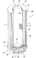
- FIG. 4 is a partial cutaway perspective view of the filter element of FIG. 3;
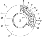
- FIG. 5 is a cross-sectional view taken along the line VV of FIG. 3; It is a principal part enlarged view of FIG. It is a perspective view of a lower end cap. It is the partially broken view of FIG.
- It is an important section sectional view of a 2nd embodiment of a filter element.
- It is an important section sectional view of a 3rd embodiment of a filter element.
- It is a sectional view showing an important section of a 4th embodiment of a filter element, and is a figure in the state where the filter element was built into a pneumatic filter.
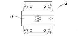
- FIG. 1 and 2 show a pneumatic filter using the filter element 1 according to the present invention.
- This pneumatic filter is one in which the hollow filter element 1 is accommodated inside the housing 2 with the axis L facing vertically via the ring-shaped partitioning member 3, and the arrow in dotted line in FIG. 1 As shown in, the compressed air flowing from the inlet port 4 is introduced into the central space 6 at the center of the filter element 1 and filtered while passing from the inner filter member 7 to the outer filter member 8, The compressed air purified by removing liquid and dust such as oil and water is configured to flow out from the outer space 9 surrounding the outer periphery of the filter element 1 through the outlet port 5. .
- the housing 2 includes a head 11 having the inlet port 4 and the outlet port 5 for connecting air piping, and a hollow housing body 12 connected to the lower part of the head 11.
- the head 11 has a rectangular shape in a plan view, the inlet port 4 is formed on one of two opposite side surfaces, and the outlet port 5 is formed on the other side surface.
- the inlet port 4 communicates with the central space 6 at the center of the filter element 1 through an inlet channel 14 formed in the conduit 13, and the outlet port 5 is an outlet channel surrounding the conduit 13.
- 15 and the communication hole 16 formed in the partition member 3 communicate with the outer space 9 formed between the outer periphery of the filter element 1 and the inner periphery of the housing 2.
- the housing body 12 has a vertically elongated cylindrical shape, and the upper end is open, and the lower end is covered with a partially spherical bottom 12a that is convex downward.
- a flange portion 12b projecting in the outer peripheral direction, and the flange portion 12b, together with the flange portion 3a on the outer periphery of the partition member 3, the lower surface of the head 11 and the fixing member 17
- the housing body 12 is connected to the head 11 by being held between and fixed to the upper end portion.
- Reference numeral 18 in the figure is a seal member interposed between the flange portion 12 b and the head 11.
- the fixing member 17 has a ring shape, and is fitted on the outer periphery of the housing main body 12 to hold the flanges 12 b and 3 a between the head 11 and the outer periphery of the housing main body 12. It is hold
- a ring-shaped support block 21 for supporting the lower end portion of the filter element 1 is disposed near the inner bottom surface of the housing main body 12.
- On the inner peripheral surface of the support block 21 are formed a plurality of fin-shaped support walls 21a projecting radially toward the center of the housing main body 12, and the lower end portion of the support wall 21a is of the housing main body 12
- the lower end portion of the filter element 1 is abutted and supported on the support wall 21a by abutting against the bottom portion 12a.
- the space 22 below the support block 21 forms a drain reservoir for storing the liquid or drain collected by the filter element 1, and the space 22 is a lower end of the filter element 1.
- a liquid discharge passage 25 formed in the cap 24 is in communication with the lower end cap 24 through a liquid discharge hole 25a opened to the lower surface of the lower end cap 24, and the drain collected by the filter element 1 is the liquid from the liquid discharge passage 25 It drips into the space 22 through the discharge hole 25a.
- a drain discharge valve 26 for discharging the drain accumulated in the space 22 is provided. Even if this drain discharge valve 26 is a manual operation type valve that rotates the drain cock to open and close the drain discharge port, the drain discharge port is automatically made according to the liquid level of the drain, the pressure of the space, etc. Although an automatic valve that opens and closes may be used, the configuration is already known even when any type of valve is used, and thus the detailed description is omitted here.
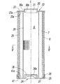
- the filter element 1 has a hollow small diameter inner filter member 7 surrounding the central space 6 and a hollow shape surrounding the outer periphery of the inner filter member 7.
- the inner filtration member 7 and the outer filtration member 8 are concentrically and double-layeredly disposed around the axis L of the filter element 1.
- the inner filtration member 7 is located upstream of the outer filtration member 8 in the flow of the compressed air, and mainly includes dust contained in the compressed air, and oil or moisture in the form of mist or droplets, etc. It collects the liquid.
- the inner filtration member 7 is formed by rolling a pleated filter medium into a cylindrical shape, and the inner filtration member 7 is formed of a punching metal and a small diameter inner support cylinder 28 and a large diameter outer side.
- the inner support cylinder 28 and the outer support cylinder 29 are disposed concentrically with the support cylinder 29. Since the inner filtration member 7 is folded in a pleated shape, the filtration area is expanded as compared with the one formed by rounding a flat sheet-like filter medium as it is. However, if it is not necessary to increase the filtration area, it is also possible to use a conventional filter member formed by rolling a flat sheet-like filter medium into a cylindrical shape.
- the outer filtration member 8 is located on the downstream side of the flow of compressed air than the inner filtration member 7 and mainly uses a liquid such as oil and water collected by the inner filtration member 7 as the lower end cap
- the outer support cylinder 29 is disposed on the outer periphery of the outer support cylinder 29 so as to surround the outer periphery of the inner filtration member 7 via the outer support cylinder 29.
- the inner filtration member 7 and the outer filtration member 8 may be, for example, a fiber sheet formed by regularly or irregularly laminating fine chemical fibers having a diameter of several ⁇ m to several tens of ⁇ m, or a chemical It can be formed of a non-woven fabric formed by bonding fibers by a method such as adhesive, fusion or entanglement, an aggregate of ceramic fine particles, a synthetic resin porous sheet or the like. Further, the inner filtration member 7 uses fine fibers with a diameter smaller than that of the outer filtration member 8 to reduce the void ratio (roughness of the mesh), thereby making it possible to form fine dust such as fine dust, oil or water.
- the outer filtration member 8 uses a larger diameter fiber than the inner filtration member 7 to increase porosity (roughness). By doing this, it is formed so that the liquid such as oil and moisture collected by the inner filtering member 7 can be led to the lower end cap 24 quickly. Therefore, it can be said that the inner filtration member 7 is a fine filtration member and the outer filtration member 8 is a coarse filtration member.
- An annular upper end cap 23 is fixed to the upper ends of the inner and outer filter members 7 and 8 with an adhesive, and a lower end of the inner and outer filter members 7 and 8 has a circular plate.
- the lower end cap 24 shaped is attached.
- the lower end cap 24 can also be fixed with an adhesive.
- a communication pipe 30 having an inlet 31 inside is formed so as to protrude in both the upper and lower directions of the upper end cap 23.
- the upper half 30a of the communication pipe 30 is shown in FIG.
- the lower end of the conduit 13 is airtightly connected via a seal member 32.
- the inlet-side flow passage 14 in the conduit 13 and the central space 6 inside the inner filtering member 7 are connected at the inlet 31, and the compressed air from the inlet port 4 is in the central space It is introduced into the section 6.
- an outer peripheral wall 23a extending downward toward the lower end cap 24 is formed at the outer peripheral end in the diameter direction of the upper end cap 23, and the inner peripheral surface of the partition member 3 is formed on the outer peripheral surface of the outer peripheral wall 23a. Is in contact.
- An annular cover 33 is formed between the lower half 30b of the communication pipe 30 and the outer peripheral wall 23a, and the inner support cylinder 28, the inner filtering member 7, and the outer support cylinder are formed in the cover 33.
- An upper end portion of the outer filtration member 8 is fitted to a flat inner bottom surface 33 a of the cover 33.
- the lower end cap 24 closes the lower end of the central space 6, and as is apparent from FIGS. 7 and 8, the central space is located at the center of the upper surface of the lower end cap 24.
- a passage 25 and a liquid discharge hole 25 a which is open on the lower surface of the lower end cap 24 and is in communication with the liquid discharge passage 25 are provided.
- the central projection 36, the inner side wall 37 and the outer side wall 38 extend parallel to the axis L toward the upper end cap 23 and the height Ho of the outer side wall 38 corresponds to that of the inner side wall 37. It is higher than the height Hi and is the same as the height of the central protrusion 36. Accordingly, the upper end surface 38a of the outer side wall 38 is located above the upper end surface 37a of the inner side wall 37, that is, at a high position in the direction of the axis L.
- the upper end surface 36 a of the central protrusion 36 is a horizontal surface.
- the outer peripheral surface of the inner side wall 37 and the inner peripheral surface of the outer side wall 38 are connected by a plurality of rib-like connecting walls 40 located radially, and the liquid discharge path 25 and the liquid between adjacent connecting walls 40, 40
- the discharge hole 25a is formed.
- the upper end surface 40a of the connection wall 40 is at the same height as the upper end surface 37a of the inner wall 37 and is horizontal, and the lower end surface 40b of the connection wall 40 is formed in a curved surface that curves upward. . Therefore, the liquid discharge passage 25 is formed at a position lower than the wall portion 38 b of the outer wall 38 extending upward from the inner wall 37.
- the lower end portions of the inner support cylinder 28, the inner filtration member 7 and the outer support cylinder 29 are fitted in the annular liquid storage chamber 41 surrounded by the central projection 36 and the inner side wall 37, respectively.
- the lower end portion of the inner filtration member abuts on the flat inner bottom surface 41a of the liquid storage chamber 41, and the outer periphery of the lower end portion of the inner filtration member 7 is surrounded by the inner side wall 37 via the outer support cylinder 29.
- the lower ends of the inner support cylinder 28, the inner filter member 7 and the outer support cylinder 29 are aligned at the same position in the direction of the axis L.
- the outer peripheral surface of the outer support cylinder 29 is in contact with the inner peripheral surface of the inner side wall 37, but may be disposed in proximity to the inner peripheral surface with a slight gap therebetween.
- the lower end portion of the outer filtration member 8 is located above the lower end portion of the inner filtration member 7 and abuts on the upper end surface 37a of the inner wall 37 and the upper end surface 40a of the connection wall 40, or The outer periphery of the lower end portion of the outer filtration member 8 is surrounded by the wall portion 38b of the outer wall 38, which is disposed close to each other with a slight gap.
- a gap 42 is formed between the outer periphery of the lower end portion of the outer filtration member 8 and the inner periphery of the outer wall 38, and the gap 42 communicates with the liquid discharge path 25.
- the space 22 communicates with the outer space 9 through the liquid discharge path 25 and the gap 42.
- the entire upper surface of the liquid discharge path 25 at the lower end portion of the outer filtration member 8 You may cover it.
- the reason for making the height Ho of the outer wall 38 higher than the height Hi of the inner wall 37 is to partially reduce the flow rate of compressed air passing near the lower ends of the inner and outer filtration members 7 and 8. Is to prevent re-scattering of the collected liquid. That is, when the flow rate of the compressed air is high, the liquid contained in high density near the lower end portions of the inner filtration member 7 and the outer filtration member 8 and the liquid accumulated in the lower end cap 24 It comes off by coming into contact with the flow and tends to be mixed again in the compressed air after purification.
- Such an anti-scattering effect of the liquid can be obtained by making the height Ho of the outer side wall 38 higher than the height Hi of the inner side wall 37 as described above, but in order to enhance the effect, it is preferable.
- the vertical width ho of the wall portion 38b in which the outer side wall 38 surrounds the lower end of the outer filtering member 8 and the vertical width hi of the wall portion 37b in which the inner side wall 37 surrounds the lower end of the inner filtering member 7 More preferably, the vertical width ho of the wall portion 38b is equal to or larger than the vertical width hi of the wall portion 37b. In the illustrated example, the vertical width ho of the wall portion 38b is twice as large as the vertical width hi of the wall portion 37b.
- the pneumatic filter having the above-mentioned configuration is connected in a pneumatic circuit and filters compressed air supplied to a pneumatic actuator such as a pneumatic cylinder or a pneumatic motor.
- a pneumatic actuator such as a pneumatic cylinder or a pneumatic motor.
- the compressed air from the porous inner support cylinder 28 When compressed air is introduced from the inlet port 4 into the central space 6 at the center of the filter element 1 through the inlet side flow passage 14 and the communication hole 16, the compressed air from the porous inner support cylinder 28, The inner filtration member 7, the porous outer support cylinder 29, and the outer filtration member 8 are sequentially passed to reach the outer space 9, and the compression is performed by the inner filtration member 7 and the outer filtration member 8 therebetween. Dust in the air and liquids such as oil and water are removed.
- the inner filtration member 7 mainly serves to collect dust in compressed air and liquid in the form of mist or droplets
- the outer filtration member 8 mainly plays the role of collecting the inner filtration member 7. Serves to guide the collected liquid to the lower end cap 24. Then, the purified compressed air flows out from the outlet port 5 from the outer space 9 through the outlet side flow passage 15 and the communication hole 16 formed in the partition member 3.
- the liquid collected by the inner filter member 7 is initially fine particles, which are gradually aggregated to become large particles, and accordingly, the inner filter member 7 and the outer filter are separated by the action of gravity. It flows down along the member 8 and combines with each other while flowing down to form larger liquid particles, which reach the lower end cap 24.
- the liquid flowing down along the inner filter member 7 temporarily stays in the liquid storage chamber 41 of the lower end cap 24, and then overflows the inner wall 37 little by little by the subsequent flow of the liquid, and the liquid In the discharge path 25, it drips down into the space 22 along the outer peripheral surface of the inner side wall 37 and the connection wall 40.
- the liquid that has flowed down along the outer filtration member 8 may have an outer peripheral surface of the inner side wall 37, a side surface of the connection wall 40, or an inner peripheral surface of the outer side wall 38 in the liquid discharge passage 25. As a result, it may drip into the space 22 but may drop directly from the lower end surface of the outer filtering member 8 into the liquid discharge path 25.
- connection wall 40 since the lower end surface 40b of the connection wall 40 is curved upward, the liquid transmitted through the connection wall 40 flows toward the inner side wall 37 or the outer side wall 38 along the lower end surface 40b. And drip from the lower end of the inner wall 37 or the outer wall 38.
- the flow passing near the lower end portions of the inner filtration member 7 and the outer filtration member 8 is the outer wall Blocked by the 38 wall portion 38b, the flow rate of that portion is reduced. Therefore, the liquid accumulated in the liquid storage chamber 41 of the lower end cap 24, the liquid overflowing the inner side wall 37, or the high density is contained in the vicinity of the lower end portions of the inner filtration member 7 and the outer filtration member 8 The liquid is not splashed by the flow of the compressed air, and therefore the splashed liquid is not mixed back into the compressed air after purification.
- the drain accumulated in the space 22 at the bottom of the housing 2 is drained by opening the drain valve 26 as required.
- FIG. 9 shows the lower end of a second embodiment of the filter element in cross section.
- the filter element 1A of the second embodiment differs from the lower end cap 24 of the filter element 1 of the first embodiment in the configuration of the lower end cap 24A. That is, the lower end cap 24 A concentrically forms the inner side wall 37 and the outer side wall 38 on the bottom wall 44 and is continuous over the entire circumference between the inner side wall 37 and the outer side wall 38.
- An annular liquid discharge passage 25 is formed, and at the bottom of the liquid discharge passage 25 is formed one or more liquid discharge holes 25 a for opening the liquid discharge passage 25 to the lower surface of the lower end cap 24.
- the other configuration of the filter element 1A is the same as the filter element 1 of the first embodiment.
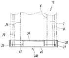
- FIG. 10 shows the lower end of the third embodiment of the filter element in cross section.
- the filter element 1B of the third embodiment differs from the lower end cap 24 of the filter element 1 of the first embodiment in the configuration of the lower end cap 24B. That is, the lower end cap 24B is obtained by concentrically integrating the inner side wall 37, the outer side wall 38 and the central protrusion 36 on the porous bottom wall 45 formed of a metal sintered body, An annular liquid discharge passage 25 formed between the inner side wall 37 and the outer side wall 38 communicates the continuous pores in the bottom wall 45 with the lower surface of the lower end cap 24 as a liquid discharge hole 25a. .
- the other configuration of the filter element 1B is the same as the filter element 1 of the first embodiment.
- the porous bottom wall 45 may be provided only at the bottom of the annular liquid discharge passage 25, and the bottom of the liquid storage chamber 41 and the central projection 36 may be a non-porous bottom wall.
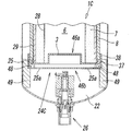
- FIG. 11 shows a lower end portion of a fourth embodiment of the filter element, and is a cross-sectional view of a state in which the filter element 1C is incorporated in a pneumatic filter.
- a lower end cap 24C is formed by an inner cap member 46a and an outer cap member 46b which are separately configured and fitted to each other.
- the inner cap member 46 a is a member that covers the lower end portion of the central space portion 6 and has a central protrusion 36 and an inner side wall 37.
- the outer cap member 46b is a plate-shaped member and has an outer wall 38 and the liquid discharge hole 25a, and a rib for supporting the outer periphery of the lower end portion of the inner cap member 46a on the inner peripheral surface. It has a plurality of inner support walls 48 shaped like a ring.
- a rib-like outer support wall 49 engaged with the inside of the housing main body 12 is radially attached to the outer surface of the outer cap member 46b, whereby the outer cap member 46b serves as the lower end of the filter element 1C.
- the liquid discharge passage 25 is formed between the inner side wall 37 and the outer side wall 38.
- the bottom wall of the outer cap member 46b may be formed in a conical surface shape, and the liquid discharge hole 25a may be provided in the center.
- the outer cap member 46b may be configured not to have the outer support wall 49, thereby eliminating the function as the support block and may have only the function as the lower end cap 24C. Further, the inner cap member 46a and the outer cap member 46b may be separable from each other, but may be integrally formed by being joined to each other by the inner support wall 48.
- the other configuration of the filter element 1C according to the fourth embodiment is the same as that of the filter element 1 according to the first embodiment, so the same main components as those in the first embodiment are denoted by the same reference numerals as in the first embodiment. The description is omitted.
- the cross-sectional shape of the filter element 1 is circular, but the cross-sectional shape may be other than circular.
- it may be a polygon such as a square or a hexagon, in which case the upper end cap and the lower end cap are similarly formed.
- the filter element is hollow inside the inner filter member 7 to protect the inner filter member 7 by removing in advance relatively large dust and the like contained in the compressed air. It is also possible to place a prefilter.
- the prefilter may be disposed either inside or outside the inner support cylinder 28.
- the inner filtration member 7 is finely formed, and the outer filtration member 8 is coarsely formed.
- the inner filtration member 7 is coarsely formed, and the outer filtration is performed.
- the member 8 can also be formed in detail.
Landscapes
- Chemical & Material Sciences (AREA)
- Chemical Kinetics & Catalysis (AREA)
- Physics & Mathematics (AREA)
- Geometry (AREA)
- Filtering Of Dispersed Particles In Gases (AREA)
- Separation Using Semi-Permeable Membranes (AREA)
- Filtration Of Liquid (AREA)
Abstract
Description
一方、前記圧縮空気から分離された油分や水分等の液体は、前記濾過部材に沿って流下する間に、小さい粒子同士が結合を繰り返すことにより次第に大きな液体粒子に成長し、前記下部キャップ内まで流下して一旦滞留したあと、該下部キャップから前記フィルタケースの内部に順次滴下し、ドレンとして排出される。
前記フィルタエレメントは、中央空間部の回りを取り囲む内側濾過部材と、該内側濾過部材の外周を取り囲む外側濾過部材とを有していて、前記中央空間部内に導入された圧縮空気が、前記内側濾過部材から前記外側濾過部材を通過する間に濾過されて前記塵埃及び液体が除去されるように構成されている。
前記内側濾過部材及び外側濾過部材の軸線方向の一端である上端部には、前記中央空間部内に圧縮空気を導入するための導入口を有する上部エンドキャップが取り付けられ、前記内側濾過部材及び外側濾過部材の軸線方向の他端である下端部には、前記中央空間部の下端部を塞ぐ下部エンドキャップが取り付けられている。
前記内側濾過部材の下端部外周は、前記下部エンドキャップに形成された内側壁で取り囲まれ、前記外側濾過部材の下端部外周は、圧縮空気の流れを遮断する外側壁で取り囲まれ、前記外側壁の上端面は前記内側壁の上端面より高い位置にある。また、前記外側壁と前記内側壁との間には、前記内側濾過部材及び外側濾過部材で捕集された液体を外部に排出するための液体排出路が形成され、該液体排出路は、前記下部エンドキャップの下面に開放する液体排出孔に連通している。
また、前記外側壁の、前記内側壁より上方で前記外側濾過部材の外周を取り囲んでいる壁部分の上下幅は、前記内側壁の、前記内側濾過部材の外周を取り囲んでいる壁部分の上下幅に対し、同等か又はそれ以上であることが望ましい。
更に、前記外側壁の内周面と前記外側濾過部材の外周面との間には、前記液体排出路に通じる隙間が形成されていても良い。
また、前記下部エンドキャップは、別構成されて相互に嵌合し合う内側キャップ部材と外側キャップ部材とを有していて、前記内側キャップ部材に前記内側壁が形成され、前記外側キャップ部材に前記外側壁と前記液体排出孔とが形成されていても良い。
この場合、前記外側キャップ部材は、前記フィルタエレメントの下端部を支持する支持ブロックを兼ねることもできる。
前記ハウジング本体12の上端部には、外周方向に張り出すフランジ部12bが形成され、該フランジ部12bが、前記仕切り部材3の外周のフランジ部3aと共に、前記ヘッド11の下面と固定部材17の上端部との間に挟持されて固定されることにより、該ハウジング本体12が前記ヘッド11に連結されている。図中の符号18は、前記フランジ部12bとヘッド11との間に介設されたシール部材である。
前記内側濾過部材7は、プリーツ状に折曲しているため、平坦なシート状の濾材をそのまま丸めて形成したものに比べ、濾過面積が拡大されている。しかし、濾過面積をそれほど大きくする必要がない場合には、平坦なシート状の濾材を円筒状に丸めて形成した通常の濾過部材を使用することもできる。
従って、前記液体排出路25は、前記外側壁38の、前記内側壁37より上方に延出している壁部分38bより低い位置に形成されていることになる。
前記外側支持筒29の外周面は、前記内側壁37の内周面に接触しているが、該内周面との間に僅かな間隙を介して近接した状態に配置されていても良い。
前記フィルタエレメント1Aのその他の構成は、前記第1実施形態のフィルタエレメント1と同じである。
前記フィルタエレメント1Bのその他の構成は、前記第1実施形態のフィルタエレメント1と同じである。
なお、前記多孔質の底壁45は、前記環状の液体排出路25の底部だけに設け、液溜室41及び中央突部36の底部は無孔の底壁としても良い。
なお、前記外側キャップ部材46bの底壁は、円錐面状に形成し、中央部に前記液体排出孔25aを設けても良い。
また、前記内側キャップ部材46aと外側キャップ部材46bとは、互いに分離自在であっても良いが、前記内側支持壁48で相互に接合することにより、一体に形成することもできる。
また、前記各実施形態において、前記フィルタエレメントには、内側濾過部材7の内側に、圧縮空気中に含まれる比較的大きな塵埃等を前もって除去することにより前記内側濾過部材7を保護する中空状のプリフィルターを配置することもできる。このプリフィルターは、前記内側支持筒28の内側又は外側のどちらに配置しても良い。
2 ハウジング
4 入口ポート
5 出口ポート
6 中央空間部
7 内側濾過部材
8 外側濾過部材
11 ヘッド
12 ハウジング本体
23 上部エンドキャップ
24,24A,24B,24C 下部エンドキャップ
25 液体排出路
25a 液体排出孔
31 導入口
37 内側壁
37a 上端面
37b 壁部分
38 外側壁
38a 上端面
38b 壁部分
40 連結壁
41 液溜室
46a 内側キャップ部材
46b 外側キャップ部材
Hi 内側壁の高さ
Ho 外側壁の高さ
hi 内側壁の壁部分の上下幅
ho 外側壁の壁部分の上下幅
Claims (17)
- 圧縮空気中に混入した塵埃及び液体を除去するための中空状をしたフィルタエレメントであって、
前記フィルタエレメントは、中央空間部の回りを取り囲む内側濾過部材と、該内側濾過部材の外周を取り囲む外側濾過部材とを有していて、前記中央空間部内に導入された圧縮空気が、前記内側濾過部材から前記外側濾過部材を通過する間に濾過されて前記塵埃及び液体が除去されるように構成され、
前記内側濾過部材及び外側濾過部材の軸線方向の一端である上端部には、前記中央空間部内に圧縮空気を導入するための導入口を有する上部エンドキャップが取り付けられ、
前記内側濾過部材及び外側濾過部材の軸線方向の他端である下端部には、前記中央空間部の下端部を塞ぐ下部エンドキャップが取り付けられ、
前記内側濾過部材の下端部外周は、前記下部エンドキャップに形成された内側壁で取り囲まれ、前記外側濾過部材の下端部外周は、圧縮空気の流れを遮断する外側壁で取り囲まれ、前記外側壁の上端面は前記内側壁の上端面より高い位置にあり、
前記外側壁と前記内側壁との間には、前記内側濾過部材及び外側濾過部材で捕集された液体を外部に排出するための液体排出路が形成され、該液体排出路は、前記下部エンドキャップの下面に開放する液体排出孔に連通している、
ことを特徴とするフィルタエレメント。 - 前記外側濾過部材の下端部は、前記内側濾過部材の下端部より高い位置にあり、且つ、前記内側壁の上端面と同等位置にあることを特徴とする請求項1に記載のフィルタエレメント。
- 前記外側壁の、前記内側壁より上方で前記外側濾過部材の外周を取り囲んでいる壁部分の上下幅は、前記内側壁の、前記内側濾過部材の外周を取り囲んでいる壁部分の上下幅に対し、同等か又はそれ以上であることを特徴とする請求項1に記載のフィルタエレメント。
- 前記外側壁の、前記内側壁より上方で前記外側濾過部材の外周を取り囲んでいる壁部分の上下幅は、前記内側壁の、前記内側濾過部材の外周を取り囲んでいる壁部分の上下幅に対し、同等か又はそれ以上であることを特徴とする請求項2に記載のフィルタエレメント。
- 前記外側壁の内周面と前記外側濾過部材の外周面との間に、前記液体排出路に通じる隙間が形成されていることを特徴とする請求項2に記載のフィルタエレメント。
- 前記外側壁の内周面と前記外側濾過部材の外周面との間に、前記液体排出路に通じる隙間が形成されていることを特徴とする請求項4に記載のフィルタエレメント。
- 前記外側壁は、前記下部エンドキャップに、前記内側壁を取り囲むように形成されていて、該外側壁と前記内側壁とは、放射状に配置された複数のリブ状の連結壁により連結されていることを特徴とする請求項1に記載のフィルタエレメント。
- 前記下部エンドキャップは、別構成されて相互に嵌合し合う内側キャップ部材と外側キャップ部材とを有していて、前記内側キャップ部材に前記内側壁が形成され、前記外側キャップ部材に前記外側壁と前記液体排出孔とが形成されていることを特徴とする請求項1に記載のフィルタエレメント。
- 入口ポート及び出口ポートを備えたヘッドと、該ヘッドに連結された中空のハウジング本体とからなるハウジング、及び、前記ハウジング本体の内部に軸線を垂直に向けて収容された中空のフィルタエレメント、を有し、前記フィルタエレメントは、中央空間部の回りを取り囲む内側濾過部材と、該内側濾過部材の外周を取り囲む外側濾過部材とを有していて、前記入口ポートから前記中央空間部内に導入された圧縮空気が、前記内側濾過部材から前記外側濾過部材を通過する間に濾過されて、前記出口ポートから流出するように構成された空気圧フィルタであって、
前記フィルタエレメントの前記内側濾過部材及び外側濾過部材の上端部には、前記入口ポートと中央空間部とを結ぶ導入口を有する上部エンドキャップが取り付けられ、前記内側濾過部材及び外側濾過部材の下端部には、前記中央空間部の下端部を塞ぐ下部エンドキャップが取り付けられ、
前記内側濾過部材の下端部外周は、前記下部エンドキャップに形成された内側壁で取り囲まれ、前記外側濾過部材の下端部外周は、圧縮空気の流れを遮断する外側壁で取り囲まれ、該外側壁の上端面は前記内側壁の上端面より高い位置にあり、
前記外側壁と前記内側壁との間には、前記内側濾過部材及び外側濾過部材で捕集された液体を前記ハウジング本体の内部に排出するための液体排出路が形成され、該液体排出路は、前記下部エンドキャップの下面に開放する液体排出孔に連通している、
ことを特徴とする空気圧フィルタ。 - 前記外側濾過部材の下端部は、前記内側濾過部材の下端部より高い位置にあり、且つ、前記内側壁の上端面と同等位置にあることを特徴とする請求項9に記載の空気圧フィルタ。
- 前記外側壁の、前記内側壁より上方で前記外側濾過部材の外周を取り囲んでいる壁部分の上下幅は、前記内側壁の、前記内側濾過部材の外周を取り囲んでいる壁部分の上下幅に対し、同等か又はそれ以上であることを特徴とする請求項9に記載の空気圧フィルタ。
- 前記外側壁の、前記内側壁より上方で前記外側濾過部材の外周を取り囲んでいる壁部分の上下幅は、前記内側壁の、前記内側濾過部材の外周を取り囲んでいる壁部分の上下幅に対し、同等か又はそれ以上であることを特徴とする請求項10に記載の空気圧フィルタ。
- 前記外側壁の内周面と前記外側濾過部材の外周面との間に、前記液体排出路に通じる隙間が形成されていることを特徴とする請求項10に記載の空気圧フィルタ。
- 前記外側壁の内周面と前記外側濾過部材の外周面との間に、前記液体排出路に通じる隙間が形成されていることを特徴とする請求項12に記載の空気圧フィルタ。
- 前記外側壁は、前記下部エンドキャップに、前記内側壁を取り囲むように形成されていて、該外側壁と前記内側壁とは、放射状に配置された複数のリブ状の連結壁により連結されていることを特徴とする請求項9に記載の空気圧フィルタ。
- 前記下部エンドキャップは、別構成されて相互に嵌合し合う内側キャップ部材と外側キャップ部材とを有していて、前記内側キャップ部材に前記内側壁が形成され、前記外側キャップ部材に前記外側壁と前記液体排出孔とが形成されていることを特徴とする請求項9に記載の空気圧フィルタ。
- 前記外側キャップ部材は、前記ハウジング本体の内部に係止することにより、前記フィルタエレメントの下端部を支持する支持ブロックを兼ねていることを特徴とする請求項16に記載の空気圧フィルタ。
Priority Applications (7)
| Application Number | Priority Date | Filing Date | Title |
|---|---|---|---|
| BR112017024042-4A BR112017024042B1 (pt) | 2015-05-11 | 2016-04-26 | Filtro pneumático e elemento de filtração |
| MX2017014143A MX2017014143A (es) | 2015-05-11 | 2016-04-26 | Filtro neumatico y elemento de filtro. |
| DE112016002154.2T DE112016002154T5 (de) | 2015-05-11 | 2016-04-26 | Pneumatischer Filter und Filterelement |
| CN201680027132.0A CN107530612B (zh) | 2015-05-11 | 2016-04-26 | 气压过滤器及过滤器元件 |
| KR1020177032076A KR102470779B1 (ko) | 2015-05-11 | 2016-04-26 | 공기압 필터 및 필터 엘리먼트 |
| RU2017142952A RU2716682C2 (ru) | 2015-05-11 | 2016-04-26 | Воздушный фильтр и фильтрующий элемент |
| US15/572,387 US10464005B2 (en) | 2015-05-11 | 2016-04-26 | Pneumatic filter and filter element |
Applications Claiming Priority (2)
| Application Number | Priority Date | Filing Date | Title |
|---|---|---|---|
| JP2015096629A JP6519862B2 (ja) | 2015-05-11 | 2015-05-11 | 空気圧フィルタ及びフィルタエレメント |
| JP2015-096629 | 2015-05-11 |
Publications (1)
| Publication Number | Publication Date |
|---|---|
| WO2016181820A1 true WO2016181820A1 (ja) | 2016-11-17 |
Family
ID=57248792
Family Applications (1)
| Application Number | Title | Priority Date | Filing Date |
|---|---|---|---|
| PCT/JP2016/062990 Ceased WO2016181820A1 (ja) | 2015-05-11 | 2016-04-26 | 空気圧フィルタ及びフィルタエレメント |
Country Status (10)
| Country | Link |
|---|---|
| US (1) | US10464005B2 (ja) |
| JP (1) | JP6519862B2 (ja) |
| KR (1) | KR102470779B1 (ja) |
| CN (1) | CN107530612B (ja) |
| BR (1) | BR112017024042B1 (ja) |
| DE (1) | DE112016002154T5 (ja) |
| MX (1) | MX2017014143A (ja) |
| RU (1) | RU2716682C2 (ja) |
| TW (1) | TWI725968B (ja) |
| WO (1) | WO2016181820A1 (ja) |
Cited By (3)
| Publication number | Priority date | Publication date | Assignee | Title |
|---|---|---|---|---|
| CN109011912A (zh) * | 2017-06-12 | 2018-12-18 | 阿特拉斯·科普柯空气动力股份有限公司 | 聚结过滤器 |
| RU2726386C1 (ru) * | 2019-10-01 | 2020-07-13 | Акционерное общество "Российская самолетостроительная корпорация "МиГ" (АО "РСК "МиГ") | Воздушный фильтр |
| JPWO2020188800A1 (ja) * | 2019-03-20 | 2020-09-24 |
Families Citing this family (14)
| Publication number | Priority date | Publication date | Assignee | Title |
|---|---|---|---|---|
| WO2017035123A1 (en) * | 2015-08-25 | 2017-03-02 | Cummins Filtration Ip, Inc | Filter precleaner |
| US10612258B2 (en) | 2016-10-22 | 2020-04-07 | Master Spas, Inc. | Filter assembly having an outer filter element and an inner filter element removably installed within the outer filter element |
| USD835233S1 (en) * | 2016-10-22 | 2018-12-04 | Master Spas, Inc. | Filter |
| CN113226508B (zh) * | 2018-07-30 | 2023-03-17 | 肖恩发展有限责任公司 | 具有掺气缓解的含水流体过滤器组件 |
| CN209155376U (zh) * | 2018-08-24 | 2019-07-26 | 深圳市贝腾科技有限公司 | 过滤装置 |
| DE102019001126A1 (de) * | 2019-02-15 | 2020-08-20 | Hydac Fluidcarecenter Gmbh | Filtervorrichtung |
| JP7292904B2 (ja) * | 2019-03-06 | 2023-06-19 | 住友重機械工業株式会社 | オイルセパレータ、フィルターエレメント、および極低温冷凍機用圧縮機 |
| CN110420517B (zh) * | 2019-08-13 | 2024-03-29 | 中国石油大学(北京) | 聚结滤芯结构以及过滤装置 |
| EP4081326A4 (en) * | 2019-12-23 | 2023-08-09 | Blade Filters Inc. | MULTIPLE CARTRIDGE AIR FILTRATION UNIT |
| RU2746559C1 (ru) * | 2020-02-26 | 2021-04-15 | Акционерное общество "Кондор" | Фильтр |
| GB202003117D0 (en) * | 2020-03-04 | 2020-04-15 | Parker Hannifin Emea Sarl | Filter element assembly |
| KR102814332B1 (ko) | 2020-04-22 | 2025-05-29 | 메르세데스-벤츠 그룹 아게 | 자동차의 공기 필터 장치 및 공기 필터 장치의 필터 부재 |
| CN112973295B (zh) * | 2021-03-18 | 2022-03-29 | 中国石油大学(北京) | 具有排液功能的聚结滤芯 |
| CN115779548A (zh) * | 2022-11-28 | 2023-03-14 | 无锡源美过滤净化设备有限公司 | 一种滤芯快速排污结构 |
Citations (7)
| Publication number | Priority date | Publication date | Assignee | Title |
|---|---|---|---|---|
| JPS609524U (ja) * | 1983-06-30 | 1985-01-23 | 株式会社 土屋製作所 | 空気圧機器用分離装置 |
| JPS6074723U (ja) * | 1983-10-25 | 1985-05-25 | シーケーデイ株式会社 | 排気フイルタ− |
| JPH04110118U (ja) * | 1991-03-13 | 1992-09-24 | 株式会社前田シエルサービス | 圧縮空気用フイルタ装置 |
| JPH07501479A (ja) * | 1991-11-26 | 1995-02-16 | プロセス サイエンティフィック イノヴェーションズ リミテッド | ガス清浄化フィルタ |
| WO2005105266A1 (en) * | 2004-04-23 | 2005-11-10 | Donaldson Company, Inc. | Mist collector arrangement and methods |
| JP2010221399A (ja) * | 2009-01-13 | 2010-10-07 | Panasonic Corp | 弾性体アクチュエータの制御装置及び制御方法、並びに、制御プログラム |
| JP2011218252A (ja) * | 2010-04-05 | 2011-11-04 | Wako Filter Technology Kk | 流体フィルタ |
Family Cites Families (27)
| Publication number | Priority date | Publication date | Assignee | Title |
|---|---|---|---|---|
| GB1473853A (en) * | 1974-02-16 | 1977-05-18 | Domnick Hunter Eng | Filters |
| US4516994A (en) * | 1984-04-11 | 1985-05-14 | Vilter Manufacturing Corporation | Apparatus for separating liquid droplets from gas |
| US5152890A (en) * | 1989-10-27 | 1992-10-06 | Pall Corporation | Filter device |
| US5180490A (en) * | 1992-01-31 | 1993-01-19 | Baldwin Filters, Inc. | Lubricant filter assembly with internal bypass lock-out |
| JPH07328364A (ja) | 1994-04-13 | 1995-12-19 | Koganei Corp | ドレン捕集フィルタおよびその製造方法 |
| US6068762A (en) * | 1995-09-29 | 2000-05-30 | Parker-Hannifin Corporation | Reusable oil filter assembly |
| US5833843A (en) * | 1995-11-13 | 1998-11-10 | Dana Corporation | Anti-drain back/pressure relieved filter cartridges |
| GB2381760B (en) * | 2001-11-12 | 2005-08-31 | Avilion Ltd | Water filter |
| GB2414196B (en) * | 2002-06-07 | 2006-06-14 | Baldwin Filters Inc | Environmentally friendly acid neutralizing full flow cartridge |
| RU2224579C1 (ru) * | 2002-07-12 | 2004-02-27 | Федеральное государственное унитарное предприятие "Тамбовский научно-исследовательский химический институт" | Способ фильтрования воздуха и устройство для его осуществления |
| US7704397B2 (en) | 2003-12-15 | 2010-04-27 | Filtran Llc | Coaxial full-flow and bypass oil filter having cap with blades |
| US7153346B2 (en) * | 2004-02-12 | 2006-12-26 | Honeywell International, Inc. | Pneumatic filter and method of making |
| GB0417455D0 (en) | 2004-08-05 | 2004-09-08 | Domnick Hunter Ltd | Filter element |
| US8057669B2 (en) * | 2005-02-22 | 2011-11-15 | Baldwin Filters, Inc. | Filter element and filter assembly including locking mechanism |
| US8292984B2 (en) * | 2007-07-20 | 2012-10-23 | Donaldson Company, Inc. | Air cleaner arrangments with end support for cartridge; components; and, methods |
| GB0715247D0 (en) * | 2007-08-04 | 2007-09-12 | Parker Hannifin Ltd | Filter assembly |
| US8480885B2 (en) * | 2009-05-18 | 2013-07-09 | Purolator Filters Na Llc | Full flow liquid filter with integral bypass filtration |
| DE102010003961A1 (de) * | 2010-01-02 | 2011-07-07 | Hydac Filtertechnik GmbH, 66280 | Filtervorrichtung sowie Filterelement zur Benutzung bei einer solchen Filtervorrichtung |
| US8828112B2 (en) * | 2010-09-07 | 2014-09-09 | Hdt Expeditionary Systems, Inc. | Air filter |
| CN201997201U (zh) * | 2010-12-24 | 2011-10-05 | 福州固力工业成套设备有限公司 | 压缩空气高效过滤器 |
| CN202036885U (zh) * | 2011-03-17 | 2011-11-16 | 派克汉尼汾液压系统(上海)有限公司 | 气体过滤器及其管型滤芯 |
| US8986539B2 (en) * | 2011-04-19 | 2015-03-24 | Cummins Filtration Ip Inc. | Inside-out flow filter with pressure recovery |
| CN103032208A (zh) * | 2011-09-30 | 2013-04-10 | 广西玉柴机器股份有限公司 | 气体发动机cng气体的低压过滤器 |
| DE102011120680A1 (de) * | 2011-12-08 | 2013-06-13 | Hydac Filtertechnik Gmbh | Filtervorrichtung und Filterelement |
| AT512506B1 (de) * | 2012-08-24 | 2013-09-15 | Ift Gmbh | Filtereinrichtung |
| CN104797320B (zh) * | 2012-10-10 | 2017-05-31 | 英格索兰公司 | 用于压缩空气过滤器的过滤器元件和过滤器杯 |
| US10434453B2 (en) * | 2014-12-31 | 2019-10-08 | Ingersoll-Rand Company | Compressor system having filter assembly with replaceable filter element holder |
-
2015
- 2015-05-11 JP JP2015096629A patent/JP6519862B2/ja active Active
-
2016
- 2016-04-26 MX MX2017014143A patent/MX2017014143A/es unknown
- 2016-04-26 DE DE112016002154.2T patent/DE112016002154T5/de active Pending
- 2016-04-26 WO PCT/JP2016/062990 patent/WO2016181820A1/ja not_active Ceased
- 2016-04-26 BR BR112017024042-4A patent/BR112017024042B1/pt not_active IP Right Cessation
- 2016-04-26 US US15/572,387 patent/US10464005B2/en active Active
- 2016-04-26 CN CN201680027132.0A patent/CN107530612B/zh active Active
- 2016-04-26 RU RU2017142952A patent/RU2716682C2/ru active
- 2016-04-26 KR KR1020177032076A patent/KR102470779B1/ko active Active
- 2016-05-03 TW TW105113728A patent/TWI725968B/zh active
Patent Citations (7)
| Publication number | Priority date | Publication date | Assignee | Title |
|---|---|---|---|---|
| JPS609524U (ja) * | 1983-06-30 | 1985-01-23 | 株式会社 土屋製作所 | 空気圧機器用分離装置 |
| JPS6074723U (ja) * | 1983-10-25 | 1985-05-25 | シーケーデイ株式会社 | 排気フイルタ− |
| JPH04110118U (ja) * | 1991-03-13 | 1992-09-24 | 株式会社前田シエルサービス | 圧縮空気用フイルタ装置 |
| JPH07501479A (ja) * | 1991-11-26 | 1995-02-16 | プロセス サイエンティフィック イノヴェーションズ リミテッド | ガス清浄化フィルタ |
| WO2005105266A1 (en) * | 2004-04-23 | 2005-11-10 | Donaldson Company, Inc. | Mist collector arrangement and methods |
| JP2010221399A (ja) * | 2009-01-13 | 2010-10-07 | Panasonic Corp | 弾性体アクチュエータの制御装置及び制御方法、並びに、制御プログラム |
| JP2011218252A (ja) * | 2010-04-05 | 2011-11-04 | Wako Filter Technology Kk | 流体フィルタ |
Cited By (12)
| Publication number | Priority date | Publication date | Assignee | Title |
|---|---|---|---|---|
| CN109011912A (zh) * | 2017-06-12 | 2018-12-18 | 阿特拉斯·科普柯空气动力股份有限公司 | 聚结过滤器 |
| WO2018229639A1 (en) | 2017-06-12 | 2018-12-20 | Atlas Copco Airpower N.V. | Coalescence filter |
| BE1025322B1 (nl) * | 2017-06-12 | 2019-01-29 | Atlas Copco Airpower Naamloze Vennootschap | Coalescentiefilter |
| US11596888B2 (en) | 2017-06-12 | 2023-03-07 | Atlas Copco Airpower, Naamloze Vennootschap | Coalescence filter |
| JPWO2020188800A1 (ja) * | 2019-03-20 | 2020-09-24 | ||
| WO2020188800A1 (ja) * | 2019-03-20 | 2020-09-24 | Smc株式会社 | フィルタエレメント |
| KR20210133975A (ko) * | 2019-03-20 | 2021-11-08 | 에스엠시 가부시키가이샤 | 필터 엘리먼트 |
| US20220176297A1 (en) * | 2019-03-20 | 2022-06-09 | Smc Corporation | Filter element |
| JP7243964B2 (ja) | 2019-03-20 | 2023-03-22 | Smc株式会社 | フィルタエレメント |
| US11980839B2 (en) | 2019-03-20 | 2024-05-14 | Smc Corporation | Filter element |
| KR102799962B1 (ko) | 2019-03-20 | 2025-04-29 | 에스엠시 가부시키가이샤 | 필터 엘리먼트 |
| RU2726386C1 (ru) * | 2019-10-01 | 2020-07-13 | Акционерное общество "Российская самолетостроительная корпорация "МиГ" (АО "РСК "МиГ") | Воздушный фильтр |
Also Published As
| Publication number | Publication date |
|---|---|
| JP2016209829A (ja) | 2016-12-15 |
| MX2017014143A (es) | 2018-03-15 |
| US20180117517A1 (en) | 2018-05-03 |
| CN107530612B (zh) | 2020-04-03 |
| DE112016002154T5 (de) | 2018-02-01 |
| BR112017024042B1 (pt) | 2022-10-04 |
| BR112017024042A2 (ja) | 2018-07-24 |
| RU2716682C2 (ru) | 2020-03-13 |
| TWI725968B (zh) | 2021-05-01 |
| RU2017142952A3 (ja) | 2019-09-24 |
| CN107530612A (zh) | 2018-01-02 |
| US10464005B2 (en) | 2019-11-05 |
| KR102470779B1 (ko) | 2022-11-25 |
| KR20180002671A (ko) | 2018-01-08 |
| TW201707767A (zh) | 2017-03-01 |
| JP6519862B2 (ja) | 2019-05-29 |
| RU2017142952A (ru) | 2019-06-11 |
Similar Documents
| Publication | Publication Date | Title |
|---|---|---|
| JP6519862B2 (ja) | 空気圧フィルタ及びフィルタエレメント | |
| US9718005B2 (en) | Fuel filter of an internal combustion engine, and filter element of a fuel filter | |
| JP4685760B2 (ja) | 燃料ろ過装置 | |
| US8025708B2 (en) | Liquid separator, particularly oil separator for compressed air systems | |
| US7081201B2 (en) | Encapsulated filter cartridge | |
| KR20100059796A (ko) | 필터 조립체 및 방법 | |
| JP6495222B2 (ja) | 合体フィルタエレメント | |
| CN102281935B (zh) | 组合式过滤器 | |
| EP3928849B1 (en) | Filter arrangement including prefiltration filter element and filter device | |
| US20140251889A1 (en) | Depth coalescing filter with barrier media patch | |
| JP2009503314A (ja) | 燃料フィルタ | |
| CN109011912B (zh) | 聚结过滤器 | |
| KR20200035028A (ko) | 액체 필터 및 액체 필터를 포함한 탱크 필터 시스템 | |
| JP2009172478A (ja) | ドレン分離装置 | |
| JP2023544380A (ja) | 水分離を伴う空気清浄器 | |
| US10617977B2 (en) | Outside-in water purification system | |
| JP4455744B2 (ja) | フィルタ装置 | |
| JP2003038916A (ja) | 交換可能なフィルターを有するフィルター要素及びフィルター装置 | |
| JP2024081897A (ja) | 圧縮空気用フィルタ装置 | |
| KR20190103837A (ko) | 정수기의 미분 방지 필터 모듈 |
Legal Events
| Date | Code | Title | Description |
|---|---|---|---|
| 121 | Ep: the epo has been informed by wipo that ep was designated in this application |
Ref document number: 16792545 Country of ref document: EP Kind code of ref document: A1 |
|
| WWE | Wipo information: entry into national phase |
Ref document number: MX/A/2017/014143 Country of ref document: MX |
|
| ENP | Entry into the national phase |
Ref document number: 20177032076 Country of ref document: KR Kind code of ref document: A |
|
| WWE | Wipo information: entry into national phase |
Ref document number: 15572387 Country of ref document: US |
|
| WWE | Wipo information: entry into national phase |
Ref document number: 112016002154 Country of ref document: DE |
|
| WWE | Wipo information: entry into national phase |
Ref document number: 2017142952 Country of ref document: RU |
|
| REG | Reference to national code |
Ref country code: BR Ref legal event code: B01A Ref document number: 112017024042 Country of ref document: BR |
|
| 122 | Ep: pct application non-entry in european phase |
Ref document number: 16792545 Country of ref document: EP Kind code of ref document: A1 |
|
| ENP | Entry into the national phase |
Ref document number: 112017024042 Country of ref document: BR Kind code of ref document: A2 Effective date: 20171108 |