WO2016178366A1 - 膜分離活性汚泥処理方法及び膜分離活性汚泥処理システム - Google Patents
膜分離活性汚泥処理方法及び膜分離活性汚泥処理システム Download PDFInfo
- Publication number
- WO2016178366A1 WO2016178366A1 PCT/JP2016/062373 JP2016062373W WO2016178366A1 WO 2016178366 A1 WO2016178366 A1 WO 2016178366A1 JP 2016062373 W JP2016062373 W JP 2016062373W WO 2016178366 A1 WO2016178366 A1 WO 2016178366A1
- Authority
- WO
- WIPO (PCT)
- Prior art keywords
- membrane separation
- activated sludge
- filtration
- biological treatment
- sludge treatment
- Prior art date
- Legal status (The legal status is an assumption and is not a legal conclusion. Google has not performed a legal analysis and makes no representation as to the accuracy of the status listed.)
- Ceased
Links
Images

Classifications
-
- B—PERFORMING OPERATIONS; TRANSPORTING
- B01—PHYSICAL OR CHEMICAL PROCESSES OR APPARATUS IN GENERAL
- B01D—SEPARATION
- B01D65/00—Accessories or auxiliary operations, in general, for separation processes or apparatus using semi-permeable membranes
- B01D65/02—Membrane cleaning or sterilisation ; Membrane regeneration
-
- B—PERFORMING OPERATIONS; TRANSPORTING
- B01—PHYSICAL OR CHEMICAL PROCESSES OR APPARATUS IN GENERAL
- B01D—SEPARATION
- B01D63/00—Apparatus in general for separation processes using semi-permeable membranes
- B01D63/02—Hollow fibre modules
-
- B—PERFORMING OPERATIONS; TRANSPORTING
- B01—PHYSICAL OR CHEMICAL PROCESSES OR APPARATUS IN GENERAL
- B01D—SEPARATION
- B01D63/00—Apparatus in general for separation processes using semi-permeable membranes
- B01D63/02—Hollow fibre modules
- B01D63/04—Hollow fibre modules comprising multiple hollow fibre assemblies
- B01D63/043—Hollow fibre modules comprising multiple hollow fibre assemblies with separate tube sheets
-
- C—CHEMISTRY; METALLURGY
- C02—TREATMENT OF WATER, WASTE WATER, SEWAGE, OR SLUDGE
- C02F—TREATMENT OF WATER, WASTE WATER, SEWAGE, OR SLUDGE
- C02F1/00—Treatment of water, waste water, or sewage
- C02F1/44—Treatment of water, waste water, or sewage by dialysis, osmosis or reverse osmosis
-
- C—CHEMISTRY; METALLURGY
- C02—TREATMENT OF WATER, WASTE WATER, SEWAGE, OR SLUDGE
- C02F—TREATMENT OF WATER, WASTE WATER, SEWAGE, OR SLUDGE
- C02F3/00—Biological treatment of water, waste water, or sewage
- C02F3/02—Aerobic processes
- C02F3/12—Activated sludge processes
-
- C—CHEMISTRY; METALLURGY
- C02—TREATMENT OF WATER, WASTE WATER, SEWAGE, OR SLUDGE
- C02F—TREATMENT OF WATER, WASTE WATER, SEWAGE, OR SLUDGE
- C02F3/00—Biological treatment of water, waste water, or sewage
- C02F3/02—Aerobic processes
- C02F3/12—Activated sludge processes
- C02F3/1236—Particular type of activated sludge installations
- C02F3/1268—Membrane bioreactor systems
- C02F3/1273—Submerged membrane bioreactors
-
- B—PERFORMING OPERATIONS; TRANSPORTING
- B01—PHYSICAL OR CHEMICAL PROCESSES OR APPARATUS IN GENERAL
- B01D—SEPARATION
- B01D2311/00—Details relating to membrane separation process operations and control
- B01D2311/04—Specific process operations in the feed stream; Feed pretreatment
-
- B—PERFORMING OPERATIONS; TRANSPORTING
- B01—PHYSICAL OR CHEMICAL PROCESSES OR APPARATUS IN GENERAL
- B01D—SEPARATION
- B01D2311/00—Details relating to membrane separation process operations and control
- B01D2311/26—Further operations combined with membrane separation processes
- B01D2311/2688—Biological processes
-
- B—PERFORMING OPERATIONS; TRANSPORTING
- B01—PHYSICAL OR CHEMICAL PROCESSES OR APPARATUS IN GENERAL
- B01D—SEPARATION
- B01D2315/00—Details relating to the membrane module operation
- B01D2315/06—Submerged-type; Immersion type
-
- B—PERFORMING OPERATIONS; TRANSPORTING
- B01—PHYSICAL OR CHEMICAL PROCESSES OR APPARATUS IN GENERAL
- B01D—SEPARATION
- B01D2317/00—Membrane module arrangements within a plant or an apparatus
- B01D2317/04—Elements in parallel
-
- B—PERFORMING OPERATIONS; TRANSPORTING
- B01—PHYSICAL OR CHEMICAL PROCESSES OR APPARATUS IN GENERAL
- B01D—SEPARATION
- B01D2321/00—Details relating to membrane cleaning, regeneration, sterilization or to the prevention of fouling
- B01D2321/18—Use of gases
- B01D2321/185—Aeration
-
- C—CHEMISTRY; METALLURGY
- C02—TREATMENT OF WATER, WASTE WATER, SEWAGE, OR SLUDGE
- C02F—TREATMENT OF WATER, WASTE WATER, SEWAGE, OR SLUDGE
- C02F2209/00—Controlling or monitoring parameters in water treatment
- C02F2209/40—Liquid flow rate
-
- C—CHEMISTRY; METALLURGY
- C02—TREATMENT OF WATER, WASTE WATER, SEWAGE, OR SLUDGE
- C02F—TREATMENT OF WATER, WASTE WATER, SEWAGE, OR SLUDGE
- C02F2303/00—Specific treatment goals
- C02F2303/16—Regeneration of sorbents, filters
-
- C—CHEMISTRY; METALLURGY
- C02—TREATMENT OF WATER, WASTE WATER, SEWAGE, OR SLUDGE
- C02F—TREATMENT OF WATER, WASTE WATER, SEWAGE, OR SLUDGE
- C02F2303/00—Specific treatment goals
- C02F2303/20—Prevention of biofouling
-
- Y—GENERAL TAGGING OF NEW TECHNOLOGICAL DEVELOPMENTS; GENERAL TAGGING OF CROSS-SECTIONAL TECHNOLOGIES SPANNING OVER SEVERAL SECTIONS OF THE IPC; TECHNICAL SUBJECTS COVERED BY FORMER USPC CROSS-REFERENCE ART COLLECTIONS [XRACs] AND DIGESTS
- Y02—TECHNOLOGIES OR APPLICATIONS FOR MITIGATION OR ADAPTATION AGAINST CLIMATE CHANGE
- Y02W—CLIMATE CHANGE MITIGATION TECHNOLOGIES RELATED TO WASTEWATER TREATMENT OR WASTE MANAGEMENT
- Y02W10/00—Technologies for wastewater treatment
- Y02W10/10—Biological treatment of water, waste water, or sewage
Definitions
- the present invention relates to a membrane separation activated sludge treatment method and a membrane separation activated sludge treatment system.
- MLR method membrane separation activated sludge method
- MF membrane microfiltration membrane
- UF membrane ultrafiltration membrane
- Examples of the purification treatment apparatus using the membrane separation activated sludge method include those in which an aeration tank and a membrane separation tank are separately provided, and those in a single tank type in which a filtration membrane is immersed in a reaction tank.
- An aeration tank is a tank that purifies sewage by allowing microorganisms propagated in large quantities to capture and consume pollutants, mainly organic matter in sewage.
- a mass of microorganisms having the ability to purify this wastewater is called activated sludge.
- Aeration means supplying oxygen by sending air to water. Oxygen may be necessary for microorganisms to live.
- aeration is performed by sending air from the lower part into the aeration tank with a blower or stirring the surface.
- the filtration membrane separates the purified water (treated water) and activated sludge in the aeration tank, but clogging (fouling) is unavoidably caused by the activated sludge adhering to the surface of the filtration membrane. For this reason, it has been proposed to remove activated sludge adhering to the surface of the filtration membrane by supplying bubbles from below the filtration membrane and rubbing (scrub) the surface of the filtration membrane with the bubbles (for example, Japanese Patent Application Laid-Open No. 2010-2010). 253355).
- the above publication discloses an apparatus configuration in which drainage (raw water) is temporarily stored in a regulating tank and can be supplied to the activated sludge tank at a constant flow rate.
- a membrane separation activated sludge treatment method is a membrane separation activated sludge treatment method comprising a step of biologically treating waste water and a step of membrane separation after the biological treatment step, wherein the membrane separation step And a plurality of filtration modules having a plurality of hollow fiber membranes aligned in one direction and a pair of holding members for fixing both ends of the plurality of hollow fiber membranes, and an inflow amount of wastewater into the biological treatment step
- the number of operations of the filtration module is varied according to the variation of the above.
- a membrane separation activated sludge treatment system is a membrane separation activated sludge treatment system comprising a tank for biologically treating wastewater and a device for membrane separation of treated water in the biological treatment tank.
- the membrane separation device includes a plurality of filtration modules having a plurality of hollow fiber membranes that are aligned in one direction and a pair of holding members that fix both ends of the plurality of hollow fiber membranes.
- the apparatus further includes a device that varies the number of operations of the filtration module in accordance with variation in the amount of wastewater flowing into the treatment tank.
- FIG. 1 is a schematic diagram showing a configuration of a membrane separation activated sludge treatment system according to an embodiment of the present invention.
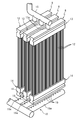
- FIG. 2 is a schematic perspective view showing a filtration block by a filtration module in the membrane separation apparatus of the membrane separation activated sludge treatment system of FIG.
- This invention is made
- the membrane separation activated sludge treatment system according to one aspect of the present invention and the membrane separation activated sludge treatment system according to another aspect can cope with fluctuations in the flow rate of waste water without using a regulating tank.
- a membrane separation activated sludge treatment method is a membrane separation activated sludge treatment method comprising a step of biologically treating waste water and a step of membrane separation after the biological treatment step, wherein the membrane separation step And a plurality of filtration modules having a plurality of hollow fiber membranes aligned in one direction and a pair of holding members for fixing both ends of the plurality of hollow fiber membranes, and an inflow amount of wastewater into the biological treatment step
- the number of operations of the filtration module is varied according to the variation of the above.
- the membrane separation activated sludge treatment method maintains the flux of treated water passing through the hollow fiber membrane by changing the number of operations of the filtration module in accordance with fluctuations in the amount of wastewater flowing into the biological treatment process. However, the discharge amount of the treated water can be adjusted according to the inflow amount of the waste water. For this reason, the said membrane separation activated sludge processing method can respond to the flow volume fluctuation
- the plurality of filtration modules may be a plurality of filtration blocks for each filtration module having a common suction system, and the number of operations of the filtration blocks may be varied in accordance with variation in the amount of wastewater flowing into the biological treatment process.
- the plurality of filtration modules are made into a plurality of filtration blocks for each filtration module having a common suction system, and the number of operations of the filtration blocks is varied according to the variation in the amount of wastewater flowing into the biological treatment process. Therefore, it is possible to simplify the control for responding to the flow rate fluctuation of the waste water.
- a plurality of cleaning modules that supply air bubbles from below the filtration module may be used, and only the cleaning module below the filtration module to be operated may be operated.
- the membrane separation step by using a plurality of cleaning modules that supply air bubbles from below the filtration module, by operating only the cleaning module below the filtration module to be operated among the plurality of cleaning modules.
- the daily minimum value of the inflow of wastewater into the biological treatment process is preferably 0.2 times or more the daily average value, and the daily maximum value of the inflow of wastewater into the biological treatment process is 2 times the daily average value. Double or less is preferable.
- the daily minimum value of the inflow of wastewater into the biological treatment process is not less than the above lower limit and the daily maximum value is not more than the above upper limit, the variation in the number of operation of the filtration module is not excessively increased and adjusted.
- a cost merit is obtained when a tank is provided to average the inflow of wastewater.
- the “daily minimum value”, “daily average value”, and “daily maximum value” mean the minimum value, average value, and maximum value for one day (24 hours) of the measured values every hour.
- a membrane separation activated sludge treatment system is a membrane separation activated sludge treatment system comprising a tank for biologically treating wastewater and a device for membrane separation of treated water in the biological treatment tank.
- the membrane separation device includes a plurality of filtration modules having a plurality of hollow fiber membranes that are aligned in one direction and a pair of holding members that fix both ends of the plurality of hollow fiber membranes.
- the apparatus further includes a device that varies the number of operations of the filtration module in accordance with variation in the amount of wastewater flowing into the treatment tank.
- the membrane separation activated sludge treatment system is provided with a device that varies the number of operations of the filtration module in accordance with fluctuations in the amount of wastewater flowing into the biological treatment tank, thereby allowing the flow of treated water that passes through the hollow fiber membrane. While maintaining the bundle, the discharge amount of the treated water can be adjusted according to the inflow amount of the waste water. For this reason, the said membrane separation activated sludge processing system can respond to the flow volume fluctuation
- the membrane separation activated sludge treatment system of FIG. 1 includes a biological treatment tank 1 for biologically treating wastewater, and a membrane separation device 2 for membrane-separating treated water in the biological treatment tank 1.
- the membrane separation activated sludge treatment system does not have an adjustment tank that adjusts the inflow of waste water. For this reason, the said membrane separation activated sludge processing system can suppress installation space and equipment cost.
- the biological treatment tank 1 is a water tank that stores water to be treated in which new wastewater that flows in and wastewater that is being treated are mixed. Wastewater flows directly into the biological treatment tank 1 from the generation source. Therefore, since the membrane separation activated sludge treatment system does not have a tank for adjusting the flow rate of the wastewater flowing into the biological treatment tank 1, the facility cost can be reduced.
- the treated water in the biological treatment tank 1 contains activated sludge (aerobic microorganisms).
- the activated sludge oxidatively decomposes or absorbs and separates organic substances in the water to be treated.
- the biological treatment tank 1 has a partition part 3, a biological treatment part 6 having a carrier 4 to which activated sludge adheres at a high concentration, and an air diffuser 5 for supplying air below the carrier 4, and a membrane separation device 2 is separated into a separation portion 7 in which 2 is disposed.
- the biological treatment unit 6 and the separation unit 7 communicate with each other, and the treated water is discharged from the separation unit 7 by the membrane separation device 2 as will be described later, so that the biological treatment unit 6 and the separation unit 7 are treated. Water flows in.
- the structure of the carrier 4 is not particularly limited as long as a plurality of activated sludges can be adhered and maintained, and for example, a porous film having a plurality of pores can be used.
- the material of the carrier 4 is not particularly limited, but polytetrafluoroethylene (PTFE) is preferably used from the viewpoints of strength, chemical resistance, and ease of hole formation.
- PTFE polytetrafluoroethylene
- the activated sludge may be attached to the carrier 4 using a flocculant.
- the carrier 4 may be fixed in the biological treatment tank 1 and may be arranged so as to swing or flow, but oxygen is efficiently added to the activated sludge carried by the bubbles supplied from the air diffuser 5. It is preferable to be arranged so that it can be supplied.
- the activated sludge can be appropriately supplied to the biological treatment tank 1 or the carrier 4 through the activated sludge addition tank and the activated sludge addition pipe (not shown).
- the membrane separation device 2 may include a device for observing the number of activated sludge in the biological treatment tank 1 by photographing or the like and automatically supplying activated sludge when the number of activated sludge becomes a lower limit value or less. Good.
- the membrane separation device 2 can draw the activated sludge from the bottom of the biological treatment tank 1, preferably from the bottom of the separation part 7, when the number of activated sludge in the biological treatment tank 1 exceeds the upper limit value. It is configured as follows.
- the membrane separation device 2 may include a device that automatically extracts the activated sludge.
- the air diffuser 5 supplies air containing oxygen to the activated sludge in the water to be treated in the biological treatment tank 1, particularly the activated sludge carried on the carrier 4. That is, the air diffuser 5 promotes reduction of organic substances by activated sludge by supplying oxygen.
- the membrane separation device 2 is connected to the plurality of filtration modules 8 capable of filtering the water to be treated, and sucks and discharges the treated water filtered by the filtration module 8 (operates the filtration module 8).
- the membrane separation activated sludge treatment system as the membrane separation device 2 includes the control device 11, as will be described in detail later, the amount of filtered water (flux) in each filtration module 8 is maintained within a certain range.
- the amount of treated water discharged can be adjusted according to the amount of wastewater flowing into the biological treatment tank 1. For this reason, the said membrane separation activated sludge processing system can respond to the flow volume fluctuation
- the filtration module 8 includes a plurality of hollow fiber membranes 12 that are aligned vertically, an upper holding member 13 that fixes the upper ends of the plurality of hollow fiber membranes 12, and the upper holding member. 13 and a lower holding member 14 that fixes the lower ends of the plurality of hollow fiber membranes 12.
- the plurality of filtration modules 8 have an upper holding member 13 and a lower holding member 14 formed in a rod shape, and a plurality of hollow fiber membranes 12 in a curtain shape along its axial direction (longitudinal direction). Lined up.
- the bundle of hollow fiber membranes 12 arranged in the form of a curtain is excellent in the cleaning efficiency by the cleaning module 10 described later, since the bubbles can relatively easily enter the central portion in the thickness direction.
- the plurality of filtration modules 8 are arranged in parallel and at equal intervals. In other words, the plurality of filtration modules 8 are held such that the longitudinal axes of the upper holding member 13 and the lower holding member 14 are parallel and equally spaced.
- the filtration module 8 is held such that the distance (straight line distance) between the pair of upper holding member 13 and lower holding member 14 is shorter than the average effective length of the hollow fiber membrane 12. It is preferable that the hollow fiber membrane 12 has a slack. More specifically, the average effective length of the hollow fiber membrane 12 is the average linear distance between both ends of the effective portion (the center of the lower surface of the portion holding the hollow fiber membrane 12 of the upper holding member 13 and the lower holding member 14 It is preferable that the distance is greater than the linear distance from the center of the upper surface of the portion that holds the hollow fiber membrane 12.
- the “average effective length” means the average length along the central axis of the portion of the hollow fiber membrane that is not held by the holding member.
- the hollow fiber membrane 12 Since the hollow fiber membrane 12 has slack in this manner, air bubbles can easily enter the bundle of the hollow fiber membranes 12, and the hollow fiber membrane 12 can swing and promote the cleaning effect by vibration thereof. .
- the hollow fiber membrane 12 is formed by tubularly forming a porous membrane that allows water to permeate while preventing permeation of impurities contained in the water to be treated.
- thermoplastic resin examples include polyethylene, polypropylene, polyvinylidene fluoride, ethylene-vinyl alcohol copolymer, polyamide, polyimide, polyetherimide, polystyrene, polysulfone, polyvinyl alcohol, polyphenylene ether, polyphenylene sulfide, cellulose acetate, and polyacrylonitrile. And polytetrafluoroethylene (PTFE).
- PTFE polytetrafluoroethylene
- PTFE which is excellent in mechanical strength, chemical resistance, heat resistance, weather resistance, nonflammability and the like and is porous is preferable, and uniaxially or biaxially stretched PTFE is more preferable.
- the material for forming the hollow fiber membrane 12 may be appropriately mixed with other polymers, additives such as a lubricant, and the like.
- the upper holding member 13 forms an internal space communicating with the lumens of the plurality of hollow fiber membranes 12 to be held, and has a drain nozzle 13a that discharges treated water filtered by the hollow fiber membranes 12 from the internal space. .
- the lower holding member 14 holds the lower end of the hollow fiber membrane 12.
- the lower holding member 14 may form an internal space similarly to the upper holding member 13, and may hold the lower end of the hollow fiber membrane 12 by a method that closes the opening of the hollow fiber membrane 12.
- the filtration module 8 may have a connecting member that connects the upper holding member 13 and the lower holding member 14 in order to facilitate handling (transportation, installation, replacement, etc.).
- a connecting member include a metal support rod and a resin casing (outer cylinder).
- the discharge mechanism 9 constitutes a suction system that sucks treated water from one or a plurality of filtration modules 8.
- the plurality of filtration modules 8 of the membrane separation device 2 are divided into a plurality of filtration blocks as shown in FIG. 2, and a discharge mechanism 9 that sucks the treated water is provided for each filtration block. Therefore, the membrane separation device 2 can be operated or stopped for each discharge mechanism 9, that is, for each filtration block constituted by a plurality of filtration modules 8 having a common suction system.
- the plurality of discharge mechanisms 9 are connected to drain nozzles 13 a of the plurality of filtration modules 8, and a water collection pipe 15 that collects treated water obtained by filtering the water to be treated by the hollow fiber membrane 12, and this water collection A suction pump 16 for sucking the treated water from the pipe 15 is provided.
- the plurality of filtration modules 8 are a plurality of filtration blocks for each filtration module 8 having a common suction system, and the control device 11 responds to fluctuations in the amount of wastewater flowing into the biological treatment tank 1. To change the number of operation of the filtration block. Therefore, in the membrane separation activated sludge treatment system, since the number of discharge mechanisms 9, that is, the filtration blocks for which the control device 11 controls the number of operations is smaller than the number of the filtration modules 8, the control for responding to the fluctuation of the waste water flow rate. Can be simplified.
- the lower limit of the daily minimum value of the inflow amount of wastewater into the biological treatment tank 1 of the membrane separation activated sludge treatment system is preferably 0.2 times the daily average value of the inflow rate, and more preferably 0.5 times.
- the upper limit of the daily maximum value of the inflow amount of wastewater into the biological treatment tank 1 is preferably twice the daily average value of the inflow amount, and more preferably 1.5 times.
- the membrane separation activated sludge treatment system operates all the filtration modules 8 when the amount of wastewater flowing into the biological treatment tank 1 is maximum, and the flux at this time is the optimum flow for the hollow fiber membrane 12. It is preferably designed to be a bundle.
- the cleaning module 10 is disposed below the plurality of filtration modules 8.
- the cleaning module 10 is preferably disposed for each filtration block.
- the cleaning module 10 only needs to be capable of discharging bubbles.
- the air supply unit 17 that supplies air and a plurality of airs disposed below the filtration module 8 are used.
- Each air header 18 may have a plurality of bubble discharge ports 19 formed therein.
- Air supply As the air supplier 17, for example, a blower, a compressor, or the like can be used.
- the air header 18 can be composed of, for example, a pipe. More specifically, as shown in FIG. 2, the air header 18 corresponds to the filtration module 8 on a one-to-one basis and extends along the region A where the hollow fiber membrane 12 is present in a plan view. It is preferable to have 18a.
- the bubble discharge ports 19 are preferably formed in a row in each pipe 18a.
- the bubble discharge ports 19 are preferably formed in a row in the longitudinal direction of the existence region A of the hollow fiber membrane 12. By arranging the bubble discharge ports 19 in the longitudinal direction of the existence area A, the bubbles released from the bubble discharge ports 19 rise along the bundle of curtain-shaped hollow fiber membranes 12, By rubbing, turbidity and the like adhering to the outer peripheral surface of the hollow fiber membrane 12 can be efficiently removed.
- control device 11 Based on the input signal from the sensor 20 that detects the amount of wastewater flowing into the biological treatment tank 1, the control device 11 operates the number of operations of the filtration module 8 and the cleaning module 10, that is, the operation of the suction pump 16 and the air supply device 17. Adjust the number.
- control device 11 for example, a personal computer, a programmable logic controller, or the like can be used.
- a flow meter or the like that detects the amount of wastewater flowing into the biological treatment tank 1 can be used.
- a flow meter suitable for the flow rate measurement of such waste water for example, a weir type flow meter and the like can be mentioned.
- the number of operations of the filtration module 8 may be determined so that the difference between the inflow amount of the wastewater detected by the sensor 20 and the total discharge amount of the treated water from the filtration module 8 is as small as possible. That is, it is preferable that the control device 11 performs control so as to increase or decrease the number of operations of the suction pump 16 (filtration block) one by one in accordance with increase or decrease of the inflow amount of waste water. In other words, it is preferable to adjust the total filtration area so that the flux is not changed as much as possible by controlling the number of operations of the filtration module 8 to be approximately proportional to the inflow amount of the waste water. In order to prevent hunting, the number of operations of the suction pump 16 may be increased or decreased by checking the detection value of the sensor 20 at regular intervals, for example, by a known control method such as PID. Good.
- the number of operation of the filtration module 8 when the inflow amount of wastewater is a daily average value is 10 and the optimum flux for the hollow fiber membrane 12 is 0.5 m / day
- the inflow amount of drainage Is 1.5 times the daily average value
- the number of operation of the filtration module 8 is 15 units
- the operation number of the filtration module 8 is
- the number of drainage inflows is 0.5 and the daily average value is 0.5 times
- the number of operation of the filtration module 8 may be controlled to be five. Thereby, even if the inflow amount of waste water fluctuates, the flux of the filtration module 8 can be maintained at 0.5 m / day.
- the control device 11 preferably continuously or intermittently operates only the cleaning module 10 below the operated filtration module 8 at the same time. Thereby, it is made not to supply air bubbles from the washing module 10 to the filtration module 8 which does not need to wash the hollow fiber membrane 12 because the operation is stopped, and as a result, the operation energy consumption of the washing module 10 is suppressed. be able to.
- control device 11 selects the filtration module 8 to be operated so that the operation time of each filtration module 8 becomes substantially equal.
- Membrane separation activated sludge treatment method [Membrane separation activated sludge treatment method] Subsequently, a membrane separation activated sludge treatment method according to an embodiment of the present invention performed using the membrane separation activated sludge treatment system will be described.
- the membrane separation activated sludge treatment method includes a step of biologically treating the waste water and a step of membrane separation after the biological treatment step.
- Bio treatment process organic matter in the water to be treated derived from the wastewater is oxidized and decomposed or absorbed and separated into activated sludge mainly in the biological treatment unit 6 of the biological treatment tank 1.
- treated water is obtained by filtering the water to be treated using the filtration module 8 and the discharge mechanism 9 of the membrane separation device 2.
- the number of operation of the filtration block composed of a plurality of filtration modules 8 is changed according to the fluctuation of the inflow amount of the wastewater into the biological treatment process.
- the membrane-separated activated sludge treatment system has been treated to pass through the hollow fiber membrane 12 by changing the number of operations of the filtration module 8 in accordance with the change in the amount of wastewater flowing into the biological treatment tank 1 (biological treatment step). While maintaining the water flux within an appropriate range, the discharge amount of the treated water can be adjusted to balance the inflow amount of the waste water. For this reason, the membrane separation activated sludge treatment system and the membrane separation activated sludge treatment method using the membrane separation activated sludge treatment system can cope with fluctuations in the flow rate of waste water without using an adjustment tank.
- the membrane separation activated sludge treatment system and the membrane separation activated sludge treatment method are connected to the same discharge mechanism 9 so as to integrally operate or stop a plurality of filtration modules 8 having a common suction system as a filtration block. Therefore, the control is relatively simple.
- the membrane separation activated sludge treatment system includes a biological treatment tank that biologically treats the water to be treated, and a filtration tank in which a filtration module is disposed to filter the treated water, and the water to be treated is filtered from the biological treatment tank.
- the sludge may be returned to the biological treatment tank from the filtration tank.
- the membrane separation activated sludge treatment system may have a discharge mechanism for each filtration module, and may be configured to vary the number of operations of the filtration module by operating or stopping for each filtration module.
- the cleaning module of the membrane separation activated sludge treatment system may have a tank or the like for storing compressed air supplied from a compressor or the like as an air supplier.
- the air supply device may be shared among a plurality of cleaning modules by providing a valve that opens and closes a ventilation path to each air header.
- a tank that stores compressed air is used as an air supply, it is difficult to reduce the energy efficiency of the air supply even if the air supply is shared by a plurality of cleaning modules.
- the inflow amount of waste water may be detected using, for example, a liquid level gauge that detects the liquid level of the biological treatment tank. Specifically, from the amount of change in the amount of treated water stored in the biological treatment tank detected by the liquid level gauge and the amount of treated water discharged from the filtration module in operation, The inflow amount can be calculated. Moreover, when using a liquid level gauge, you may control not to calculate the inflow amount of waste_water
- the liquid level height of the biological treatment tank is confirmed with a liquid level meter at regular intervals, and if the liquid level height is equal to or higher than a preset upper limit height, filtration is performed.
- a method of decreasing the operation of the filtration block (suction pump) by one is mentioned.
- the membrane separation activated sludge treatment system may have an adjustment tank that adjusts the inflow amount of waste water. For example, by providing a comparatively small capacity adjustment tank, the peak of the drainage inflow amount can be cut, and the number of filtration modules can be reduced.
- air bubbles may be supplied from the cleaning module to the stopped filtration module. In this case, you may perform the backwash which supplies processed water etc. to the filtration module from the discharge mechanism side.
Landscapes
- Chemical & Material Sciences (AREA)
- Life Sciences & Earth Sciences (AREA)
- Chemical Kinetics & Catalysis (AREA)
- Hydrology & Water Resources (AREA)
- Engineering & Computer Science (AREA)
- Environmental & Geological Engineering (AREA)
- Water Supply & Treatment (AREA)
- Organic Chemistry (AREA)
- Biodiversity & Conservation Biology (AREA)
- Microbiology (AREA)
- Separation Using Semi-Permeable Membranes (AREA)
- Activated Sludge Processes (AREA)
Abstract
Description
上記公報に開示される膜分離活性汚泥処理システムでは、排水を安定して処理可能とするために、排水の発生量の変動を吸収できるよう十分に大きな容量を有する調整槽を設ける必要がある。しかしながら、例えば昼間のみ稼働する工場等では、排水の発生量の変動が大きく、十分な容量を有する調整槽を設けることは、設備コストを大きく押し上げるという不都合がある。
本発明の一態様に係る膜分離活性汚泥処理システム及び別の態様に係る膜分離活性汚泥処理システムは、調整槽を使用することなく排水の流量変動に対応できる。
本発明の一態様に係る膜分離活性汚泥処理方法は、排水を生物処理する工程と、この生物処理工程後に膜分離する工程とを備える膜分離活性汚泥処理方法であって、上記膜分離工程で、一方向に引き揃えられる複数本の中空糸膜及びこれらの複数本の中空糸膜の両端を固定する一対の保持部材を有する複数の濾過モジュールを用い、上記生物処理工程への排水の流入量の変動に応じて上記濾過モジュールの運転数を変動させる。
以下、本発明に係る膜分離活性汚泥処理システムの実施形態について図面を参照しつつ詳説する。
図1の膜分離活性汚泥処理システムは、排水を生物処理する生物処理槽1と、この生物処理槽1での処理水を膜分離する膜分離装置2とを備える。
生物処理槽1は、流入する新たな排水と処理中の排水とが混合された被処理水を貯留する水槽である。この生物処理槽1には、発生源から排水が直接流入する。従って、当該膜分離活性汚泥処理システムは、生物処理槽1に流入する排水の流量を調整する槽を有しないため、設備コストを低減できる。
担体4の構造としては、複数の活性汚泥を付着維持できる構造であれば特に限定されず、例えば複数の孔を有する多孔質膜等とすることができる。また、この担体4の材質としては特に限定されないが、強度、耐薬品性、空孔形成容易性等の観点からポリテトラフルオロエチレン(PTFE)を用いることが好ましい。なお、凝集剤を用いて担体4に活性汚泥を付着させてもよい。
散気装置5は、生物処理槽1内の被処理水中の活性汚泥、特に担体4に担持されている活性汚泥に酸素を含む空気を供給する。つまり、散気装置5は、酸素の供給によって活性汚泥による有機物の低減を促進する。
膜分離装置2は、被処理水を濾過できる複数の濾過モジュール8と、この複数の濾過モジュール8に接続され、濾過モジュール8が濾過した処理済水を吸引して排出(濾過モジュール8を運転)する複数の排出機構9と、濾過モジュール8の下方から気泡を供給する1又は複数の洗浄モジュール10と、生物処理槽1への排水の流入量の変動に応じて濾過モジュール8の運転数(つまり排出機構9の運転数)を変動させる制御装置11とを備える。
濾過モジュール8は、図2に示すように、上下に引き揃えられる複数本の中空糸膜12と、これらの複数本の中空糸膜12の上端を固定する上側保持部材13と、この上側保持部材13と対をなし、上記複数本の中空糸膜12の下端を固定する下側保持部材14とをそれぞれ有する。
中空糸膜12は、水を透過させる一方、被処理水に含まれる不純物の透過を阻止する多孔性の膜を管状に成形したものである。
上側保持部材13は、保持する複数本の中空糸膜12の内腔と連通する内部空間を形成し、この内部空間から中空糸膜12によって濾過された処理済水を排出する排水ノズル13aを有する。
下側保持部材14は、中空糸膜12の下端を保持する。下側保持部材14は、上記上側保持部材13と同様に内部空間を形成してもよく、中空糸膜12の開口を閉塞するような方法で中空糸膜12の下端を保持してもよい。
排出機構9は、1又は複数の濾過モジュール8から処理済水を吸引する吸引系を構成する。換言すると、膜分離装置2の複数の濾過モジュール8は、図2に示すような複数の濾過ブロックに区分され、各濾過ブロック毎に処理済水を吸引する排出機構9が設けられる。従って、膜分離装置2では、排出機構9毎、つまり吸引系が共通する複数の濾過モジュール8から構成される濾過ブロック毎に運転又は停止することができる。
洗浄モジュール10は、図1及び図2に示すように、複数の濾過モジュール8の下方に配設される。この洗浄モジュール10は、濾過ブロック毎に配設されることが好ましい。
空気供給器17としては、例えばブロワー、コンプレッサー等を用いることができる。
空気ヘッダー18は、例えばパイプ等で構成することができる。より具体的には、空気ヘッダー18は、図2に示すように、濾過モジュール8に一対一に対応し、平面視で中空糸膜12の存在領域Aに沿って延在する1又は複数のパイプ18aを有することが好ましい。気泡吐出口19は、各パイプ18aに一列に並んで形成するとよい。
気泡吐出口19は、中空糸膜12の存在領域Aの長手方向に列をなして形成されることが好ましい。気泡吐出口19が存在領域Aの長手方向に列設されることによって、気泡吐出口19から放出される気泡が、カーテン状の中空糸膜12の束に沿って上昇し、中空糸膜12を擦過することによって、中空糸膜12の外周面に付着している濁質等を効率よく除去することができる。
制御装置11は、生物処理槽1への排水の流入量を検出するセンサー20からの入力信号に基づいて、濾過モジュール8及び洗浄モジュール10の運転数、つまり吸引ポンプ16及び空気供給器17の運転台数を調節する。
続いて、当該膜分離活性汚泥処理システムを用いて行われる本発明の一実施形態に係る膜分離活性汚泥処理方法について説明する。
生物処理工程では、上記生物処理槽1の主に生物処理部6において排水に由来する被処理水中の有機物を活性汚泥に酸化分解又は吸収分離させる。
膜分離工程では、膜分離装置2の濾過モジュール8及び排出機構9を用いて、被処理水を濾過することによって処理済水を得る。
当該膜分離活性汚泥処理システムは、生物処理槽1(生物処理工程)への排水の流入量の変動に応じて濾過モジュール8の運転数を変動させることによって、中空糸膜12を通過する処理済水の流束を適当な範囲内に維持しながら、排水の流入量とバランスするように処理水の排出量を調整することができる。このため、当該膜分離活性汚泥処理システム及び当該膜分離活性汚泥処理システムを用いる当該膜分離活性汚泥処理方法は、調整槽を使用することなく排水の流量変動に対応できる。
今回開示された実施の形態は全ての点で例示であって制限的なものではないと考えられるべきである。本発明の範囲は、上記実施形態の構成に限定されるものではなく、特許請求の範囲によって示され、特許請求の範囲と均等の意味及び範囲内での全ての変更が含まれることが意図される。
2 膜分離装置
3 仕切部
4 担体
5 散気装置
6 生物処理部
7 分離部
8 濾過モジュール
9 排出機構
10 洗浄モジュール
11 制御装置
12 中空糸膜
13 上側保持部材
13a 排水ノズル
14 下側保持部材
15 集水配管
16 吸引ポンプ
17 空気供給器
18 空気ヘッダー
18a パイプ
19 気泡吐出口
20 センサー
Claims (6)
- 排水を生物処理する工程と、この生物処理工程後に膜分離する工程とを備える膜分離活性汚泥処理方法であって、
上記膜分離工程で、一方向に引き揃えられる複数本の中空糸膜及びこれらの複数本の中空糸膜の両端を固定する一対の保持部材を有する複数の濾過モジュールを用い、
上記生物処理工程への排水の流入量の変動に応じて上記濾過モジュールの運転数を変動させる膜分離活性汚泥処理方法。 - 上記複数の濾過モジュールを吸引系が共通する濾過モジュール毎の複数の濾過ブロックとし、
上記生物処理工程への排水の流入量の変動に応じて上記濾過ブロックの運転数を変動させる請求項1に記載の膜分離活性汚泥処理方法。 - 上記膜分離工程で、上記濾過モジュールの下方から気泡を供給する複数の洗浄モジュールを用い、
これらの複数の洗浄モジュールのうち運転する濾過モジュールの下方の洗浄モジュールのみを運転する請求項1又は請求項2に記載の膜分離活性汚泥処理方法。 - 上記生物処理工程への排水の流入量の日最小値が日平均値の0.2倍以上であり、上記生物処理工程への排水の流入量の日最大値が日平均値の2倍以下である請求項1、請求項2又は請求項3に記載の膜分離活性汚泥処理方法。
- 排水を生物処理する槽と、この生物処理槽での処理水を膜分離する装置とを備える膜分離活性汚泥処理システムであって、
上記膜分離装置が、一方向に引き揃えられる複数本の中空糸膜及びこれらの複数本の中空糸膜の両端を固定する一対の保持部材を有する複数の濾過モジュールを有し、
上記生物処理槽への排水の流入量の変動に応じて上記濾過モジュールの運転数を変動させる装置をさらに備える膜分離活性汚泥処理システム。 - 上記生物処理槽に流入する排水の流量を調整する槽を有しない請求項5に記載の膜分離活性汚泥処理システム。
Priority Applications (4)
| Application Number | Priority Date | Filing Date | Title |
|---|---|---|---|
| CN201680020516.XA CN107531529A (zh) | 2015-05-07 | 2016-04-19 | 膜分离活性污泥处理方法以及膜分离活性污泥处理系统 |
| JP2016554701A JPWO2016178366A1 (ja) | 2015-05-07 | 2016-04-19 | 膜分離活性汚泥処理方法及び膜分離活性汚泥処理システム |
| US15/562,948 US20180111096A1 (en) | 2015-05-07 | 2016-04-19 | Membrane separation type activated sludge treatment method and membrane separation type activated sludge treatment system |
| TW105113122A TW201704157A (zh) | 2015-05-07 | 2016-04-27 | 膜分離活性污泥處理方法及膜分離活性污泥處理系統 |
Applications Claiming Priority (2)
| Application Number | Priority Date | Filing Date | Title |
|---|---|---|---|
| JP2015094657 | 2015-05-07 | ||
| JP2015-094657 | 2015-05-07 |
Publications (1)
| Publication Number | Publication Date |
|---|---|
| WO2016178366A1 true WO2016178366A1 (ja) | 2016-11-10 |
Family
ID=57217652
Family Applications (1)
| Application Number | Title | Priority Date | Filing Date |
|---|---|---|---|
| PCT/JP2016/062373 Ceased WO2016178366A1 (ja) | 2015-05-07 | 2016-04-19 | 膜分離活性汚泥処理方法及び膜分離活性汚泥処理システム |
Country Status (5)
| Country | Link |
|---|---|
| US (1) | US20180111096A1 (ja) |
| JP (1) | JPWO2016178366A1 (ja) |
| CN (1) | CN107531529A (ja) |
| TW (1) | TW201704157A (ja) |
| WO (1) | WO2016178366A1 (ja) |
Cited By (3)
| Publication number | Priority date | Publication date | Assignee | Title |
|---|---|---|---|---|
| JP2017109156A (ja) * | 2015-12-15 | 2017-06-22 | メタウォーター株式会社 | 浄水システムの制御方法及び浄水システム |
| WO2018181618A1 (ja) * | 2017-03-28 | 2018-10-04 | 東レ株式会社 | 膜分離活性汚泥における廃水処理方法、廃水処理装置および廃水処理システム管理プログラム |
| WO2025110077A1 (ja) * | 2023-11-21 | 2025-05-30 | 株式会社クボタ | 水処理装置の運転方法および水処理装置 |
Families Citing this family (1)
| Publication number | Priority date | Publication date | Assignee | Title |
|---|---|---|---|---|
| WO2017086313A1 (ja) * | 2015-11-19 | 2017-05-26 | 株式会社クラレ | 中空糸膜モジュール及びその洗浄方法 |
Citations (6)
| Publication number | Priority date | Publication date | Assignee | Title |
|---|---|---|---|---|
| JPH04267986A (ja) * | 1991-02-22 | 1992-09-24 | Ebara Corp | 流量変動対応型排水処理装置 |
| JPH07155758A (ja) * | 1993-12-07 | 1995-06-20 | Mitsubishi Rayon Co Ltd | 廃水処理装置 |
| JP2001334130A (ja) * | 2000-05-30 | 2001-12-04 | Kubota Corp | 流量調整機能付き膜分離ユニット |
| JP2006007103A (ja) * | 2004-06-25 | 2006-01-12 | Kobelco Eco-Solutions Co Ltd | 膜分離汚水処理装置及びその運転方法 |
| WO2009004725A1 (ja) * | 2007-07-04 | 2009-01-08 | Mitsubishi Rayon Engineering Co., Ltd. | 散気装置の洗浄方法 |
| JP2011147868A (ja) * | 2010-01-20 | 2011-08-04 | Hitachi Plant Technologies Ltd | 廃水処理システム、及び廃水処理方法 |
Family Cites Families (3)
| Publication number | Priority date | Publication date | Assignee | Title |
|---|---|---|---|---|
| JPH04267998A (ja) * | 1991-02-22 | 1992-09-24 | Ebara Corp | 流量変動対応型排水処理装置 |
| JP2008264772A (ja) * | 2007-03-27 | 2008-11-06 | Asahi Kasei Chemicals Corp | 膜分離活性汚泥装置及び有機物含有水の処理方法 |
| SG186047A1 (en) * | 2010-06-30 | 2013-01-30 | Sumitomo Elec Fine Polymer Inc | Immersion type membrane module unit and membrane separation activated sludge process equipment |
-
2016
- 2016-04-19 JP JP2016554701A patent/JPWO2016178366A1/ja active Pending
- 2016-04-19 US US15/562,948 patent/US20180111096A1/en not_active Abandoned
- 2016-04-19 CN CN201680020516.XA patent/CN107531529A/zh active Pending
- 2016-04-19 WO PCT/JP2016/062373 patent/WO2016178366A1/ja not_active Ceased
- 2016-04-27 TW TW105113122A patent/TW201704157A/zh unknown
Patent Citations (6)
| Publication number | Priority date | Publication date | Assignee | Title |
|---|---|---|---|---|
| JPH04267986A (ja) * | 1991-02-22 | 1992-09-24 | Ebara Corp | 流量変動対応型排水処理装置 |
| JPH07155758A (ja) * | 1993-12-07 | 1995-06-20 | Mitsubishi Rayon Co Ltd | 廃水処理装置 |
| JP2001334130A (ja) * | 2000-05-30 | 2001-12-04 | Kubota Corp | 流量調整機能付き膜分離ユニット |
| JP2006007103A (ja) * | 2004-06-25 | 2006-01-12 | Kobelco Eco-Solutions Co Ltd | 膜分離汚水処理装置及びその運転方法 |
| WO2009004725A1 (ja) * | 2007-07-04 | 2009-01-08 | Mitsubishi Rayon Engineering Co., Ltd. | 散気装置の洗浄方法 |
| JP2011147868A (ja) * | 2010-01-20 | 2011-08-04 | Hitachi Plant Technologies Ltd | 廃水処理システム、及び廃水処理方法 |
Cited By (8)
| Publication number | Priority date | Publication date | Assignee | Title |
|---|---|---|---|---|
| JP2017109156A (ja) * | 2015-12-15 | 2017-06-22 | メタウォーター株式会社 | 浄水システムの制御方法及び浄水システム |
| WO2018181618A1 (ja) * | 2017-03-28 | 2018-10-04 | 東レ株式会社 | 膜分離活性汚泥における廃水処理方法、廃水処理装置および廃水処理システム管理プログラム |
| CN110494395A (zh) * | 2017-03-28 | 2019-11-22 | 东丽株式会社 | 膜分离活性污泥的废水处理方法、废水处理装置和废水处理系统管理程序 |
| JPWO2018181618A1 (ja) * | 2017-03-28 | 2020-02-06 | 東レ株式会社 | 膜分離活性汚泥における廃水処理方法、廃水処理装置および廃水処理システム管理プログラム |
| US11414331B2 (en) | 2017-03-28 | 2022-08-16 | Toray Industries, Inc. | Effluent treatment method for membrane separation activated sludge, effluent treatment apparatus, and effluent treatment system management program |
| JP7188078B2 (ja) | 2017-03-28 | 2022-12-13 | 東レ株式会社 | 膜分離活性汚泥における廃水処理方法、廃水処理装置および廃水処理システム管理プログラム |
| CN110494395B (zh) * | 2017-03-28 | 2023-08-15 | 东丽株式会社 | 膜分离活性污泥的废水处理方法、废水处理装置和废水处理系统管理程序 |
| WO2025110077A1 (ja) * | 2023-11-21 | 2025-05-30 | 株式会社クボタ | 水処理装置の運転方法および水処理装置 |
Also Published As
| Publication number | Publication date |
|---|---|
| US20180111096A1 (en) | 2018-04-26 |
| TW201704157A (zh) | 2017-02-01 |
| CN107531529A (zh) | 2018-01-02 |
| JPWO2016178366A1 (ja) | 2018-03-01 |
Similar Documents
| Publication | Publication Date | Title |
|---|---|---|
| US20130264254A1 (en) | Oil-containing wastewater treatment system | |
| JP5822264B2 (ja) | 膜分離活性汚泥処理装置の運転方法 | |
| EP2980029B1 (en) | Operating method for organic wastewater treatment device and organic wastewater treatment device | |
| KR100645952B1 (ko) | 폐수 정화용 중공사막 여과 장치, 여과 모듈 및 그를 이용하는 물 또는 폐수 처리 방법 | |
| KR101050374B1 (ko) | 소규모 하수처리시설의 자동 운전장치 | |
| JP5803293B2 (ja) | 散気装置 | |
| KR102400040B1 (ko) | 수두차를 이용한 막여과 고도정수처리 장치 및 그 동압 제어 방법 | |
| WO2012002427A1 (ja) | 浸漬型膜モジュールユニット、及び膜分離活性汚泥処理装置 | |
| JPWO2016178366A1 (ja) | 膜分離活性汚泥処理方法及び膜分離活性汚泥処理システム | |
| JP2010253355A (ja) | 膜分離活性汚泥処理装置 | |
| JP5845673B2 (ja) | 散気装置 | |
| WO2018051630A1 (ja) | 膜分離活性汚泥処理システム | |
| US10040030B2 (en) | Filtration device having internal recirculation | |
| JP2006255587A (ja) | 水処理方法 | |
| JP5126153B2 (ja) | 膜分離活性汚泥処理装置 | |
| KR101522254B1 (ko) | 유동적 회수율을 갖는 2단 막여과 시스템 및 이의 운전방법 | |
| WO2017057501A1 (ja) | 膜分離活性汚泥処理方法及び膜分離活性汚泥処理システム | |
| JP7122761B2 (ja) | 水浄化システム | |
| JP2010046561A (ja) | 汚泥脱水濃縮方法及びその装置 | |
| JP3688146B2 (ja) | 浄化槽 | |
| KR102315906B1 (ko) | 수두차를 이용한 막여과 고도정수처리 장치 | |
| JPWO2014192416A1 (ja) | 濾過装置及びこれを用いた濾過方法 | |
| JP2024087250A (ja) | 膜ろ過装置及びそれを用いた浄水システム | |
| CN203741156U (zh) | 精细水处理成套装置 | |
| KR20140008039A (ko) | 침지식 막 여과장치를 사용하는 하수처리시설 및 이를 이용하여 에너지를 절약하는 방법 |
Legal Events
| Date | Code | Title | Description |
|---|---|---|---|
| ENP | Entry into the national phase |
Ref document number: 2016554701 Country of ref document: JP Kind code of ref document: A |
|
| 121 | Ep: the epo has been informed by wipo that ep was designated in this application |
Ref document number: 16789502 Country of ref document: EP Kind code of ref document: A1 |
|
| WWE | Wipo information: entry into national phase |
Ref document number: 15562948 Country of ref document: US |
|
| NENP | Non-entry into the national phase |
Ref country code: DE |
|
| 122 | Ep: pct application non-entry in european phase |
Ref document number: 16789502 Country of ref document: EP Kind code of ref document: A1 |