WO2016175212A1 - シートバックフレーム - Google Patents
シートバックフレーム Download PDFInfo
- Publication number
- WO2016175212A1 WO2016175212A1 PCT/JP2016/063085 JP2016063085W WO2016175212A1 WO 2016175212 A1 WO2016175212 A1 WO 2016175212A1 JP 2016063085 W JP2016063085 W JP 2016063085W WO 2016175212 A1 WO2016175212 A1 WO 2016175212A1
- Authority
- WO
- WIPO (PCT)
- Prior art keywords
- frame
- width direction
- seat back
- rear wall
- contact
- Prior art date
- Legal status (The legal status is an assumption and is not a legal conclusion. Google has not performed a legal analysis and makes no representation as to the accuracy of the status listed.)
- Ceased
Links
Images




Classifications
-
- B—PERFORMING OPERATIONS; TRANSPORTING
- B60—VEHICLES IN GENERAL
- B60N—SEATS SPECIALLY ADAPTED FOR VEHICLES; VEHICLE PASSENGER ACCOMMODATION NOT OTHERWISE PROVIDED FOR
- B60N2/00—Seats specially adapted for vehicles; Arrangement or mounting of seats in vehicles
- B60N2/64—Back-rests or cushions
-
- B—PERFORMING OPERATIONS; TRANSPORTING
- B60—VEHICLES IN GENERAL
- B60N—SEATS SPECIALLY ADAPTED FOR VEHICLES; VEHICLE PASSENGER ACCOMMODATION NOT OTHERWISE PROVIDED FOR
- B60N2/00—Seats specially adapted for vehicles; Arrangement or mounting of seats in vehicles
- B60N2/68—Seat frames
Definitions
- the present invention relates to a seat back frame, and more particularly, to a seat back frame including a communication frame that connects lower end portions of a pair of side frames.
- the seat back of a vehicle seat has a seat back frame as its skeleton.
- a configuration of the seat back frame a configuration including side frames at both ends in the seat width direction is generally known.
- Some seat back frames include a communication frame that connects the lower ends of each of the pair of side frames. This communication frame functions as a lower member frame, for example. That is, the lower end portions of the pair of side frames are brought into contact with each other by causing both end portions in the seat width direction of the connection frames to contact the rear walls of the corresponding side frames.
- the end portion in the seat width direction of the communication frame that is in contact with the rear wall of the side frame extends upward. There is something.
- the contact area between the rear wall of the side frame and the connecting frame is increased, and thus the rigidity at the contact portion is increased.
- the rigidity against the force (strictly speaking, the compressive force) acting on the rear wall of the side frame when a rearward load is applied to the seat back is improved.
- some seat back frames provided with a contact frame have holes formed at the end of the contact frame in the seat width direction as shown in Patent Document 2 for the purpose of weight reduction.
- Patent Document 2 a hole is formed at the end of the connecting frame in the sheet width direction.
- a cutout may be formed instead of the hole.
- the contact area between the connection frame and the side frame is reduced by the amount of the notch formed. When the contact area decreases, it becomes difficult to ensure the rigidity of the rear wall of the side frame.
- an object of the present invention is to provide a seat that can appropriately abut the contact frame on the rear wall of the side frame while ensuring the rigidity of the side frame.
- an object of the present invention is to provide a seat back frame capable of appropriately ensuring the rigidity of the rear wall of the side frame while providing a notch at the end of the connecting frame in the seat width direction.
- the subject is a pair of side frames that are spaced apart in the width direction of the seat back, and a communication frame that connects the lower ends of each of the pair of side frames
- Each of the pair of side frames has a side wall forming both ends of the seat back in the width direction, and a rear wall extending inward in the width direction from a rear end portion of the side wall.
- the rear wall is provided with a raised portion formed so as to extend in the vertical direction, and the end portion in the width direction of the connection frame is formed of a corresponding side frame of the pair of side frames.
- a contact portion that contacts the rear wall, and the contact portion is formed at an upper extension portion extending upward along the rear wall and at an upper end portion of the upper extension portion; Engage with bottom edge of ridge
- the contact portion of the end portion of the connecting frame in the width direction of the seat back (hereinafter simply referred to as the width direction) is in contact with the rear wall of the side frame. Along the top. Further, a raised portion extending in the vertical direction is formed on the rear wall of the side frame. With such a configuration, it is possible to effectively ensure the rigidity of the rear wall of the side frame. Further, of the contact portion of the connecting frame with the rear wall of the side frame at the end portion in the width direction, the upper end portion of the upper extension portion extending upward along the rear wall is engaged with the lower end portion of the raised portion. A mating engagement portion is provided.
- connection frame contact abuts to the rear wall of a side frame in the state which the lower end part of the protruding part engaged with the engaging part.
- the end portion in the width direction of the connection frame includes the contact portion that contacts the front surface of the rear wall of the corresponding side frame, and the side wall of the corresponding side frame. It is preferable that the upper extending portion and the protruding portion in the contact portion are adjacent to each other in a state of crossing each other. According to said structure, the contact part with a side frame and the protrusion part which protruded ahead are provided in the width direction edge part of the connection frame. Thereby, the rigidity of the rear wall of the side frame can be further increased.
- the end portion in the width direction of the connecting frame further includes a second projecting portion that is formed at a position facing the projecting portion in the width direction and projects forward.
- the second projecting portion may be adjacent to the projecting portion on the side opposite to the projecting portion in a state intersecting with the upward extending portion in the contact portion.
- connection frame is made of a plate-like member, and has a flange portion formed by bending the upper end portion of the connection frame forward, and the flange portion is It is good to form to the position which reaches the upper extension part, and the part which reached the upper extension part among the flange parts may constitute the 2nd projection part.
- the flange part formed in the upper end part of a connection frame reaches the width direction edge part (more specifically, it is an upward extension part among contact parts with a side frame). ing. Thereby, the rigidity of the rear wall of the side frame can be further increased.
- the portion of the flange portion that has reached the upwardly extending portion is formed by bending the end portion on the inner side of the rear wall in the width direction toward the front. It is good to line up along the part adjacent to the said upward extension part among wall side flange parts.
- the flange part which reached the width direction edge part (more specifically, it is an upper extension part among contact parts with a side frame), and the position adjacent to the said flange part
- the side frame flange portions (rear wall side flange portions) provided side by side are aligned. Thereby, the reinforcement effect by the flange part of a side frame can further be heightened by the flange part of a connection frame.
- the connecting frame since the connecting frame is bent at an intermediate position in the width direction, the central portion in the width direction of the connecting frame is more than the upward extending portion in the contact portion. It is good to be located forward. According to said structure, since the center part of the width direction of a connection frame is located ahead, the space
- the connecting frame may include a second raised portion formed so as to extend in the width direction at a center portion in the width direction. According to said structure, the rigidity of a connection frame comes to improve further by providing a 2nd protruding part.
- the connecting frame since the connecting frame is bent at an intermediate position in the width direction, the center portion in the width direction of the connecting frame is more than the upward extending portion of the contact portion. It is good to be located ahead and the bent part of the connecting frame in the width direction is good to be located outside the second raised part. According to said structure, the part in which the 2nd protruding part is provided among the connection frames is located ahead. As a result, it is possible to widen the distance from the feet (particularly the shin portion) of the seated person who is seated in the rear seat, and to secure a space around the feet.
- the end portion in the width direction of the connection frame includes the contact portion that contacts the front surface of the rear wall of the corresponding side frame, and the side wall of the corresponding side frame.
- a second abutting portion that abuts on the inner side surface of the abutting portion, and the upwardly extending portion in the abutting portion and the second abutting portion are adjacent to each other while intersecting each other.
- abuts to the rear wall of a side frame, and the 2nd contact part similarly provided in the width direction edge part is a side frame. It is in contact with the side wall.
- the engaging portion is a notch formed at an upper end portion of the upward extending portion, and the lower end portion of the raised portion enters the notched portion, thereby the raised portion. It is good to engage with the lower end part. According to said structure, it becomes easy to engage the upward extension part of the contact part provided in the width direction edge part of the connection frame with the protruding part provided in the rear wall of the side frame.
- the notch as the engaging portion when the communication frame is brought into contact with the rear wall of the side frame, the end of the connecting frame in the width direction with respect to the rear wall of the side frame. It becomes possible to position the part.
- both end portions in the width direction of the communication frame have the contact portions, and the vertical length of each end portion in the width direction of the connection frame is the contact length. It may be longer than the vertical length of the central portion in the width direction of the frame. According to said structure, it becomes possible to make a contact frame contact
- the abutting portion further includes a downward extending portion extending downward along the rear wall.
- the contact area between the rear wall of the side frame and the connection frame is further increased by providing the downwardly extending portion at the end in the width direction of the connection frame.
- the rigidity can be further increased.
- the lower extension portion may extend to the bottom side of the corresponding side frame and extend along the bottom surface. According to the above configuration, since the downward extending portion extends along the bottom surface of the side frame, the contact area between the rear wall of the side frame and the connection frame is further increased. The rigidity can be further increased.
- each of the pair of side frames has a side flange portion formed by bending an outer edge of the side wall outward in the width direction, and the width of the communication frame
- the end portion in the direction has a continuous portion that is continuous with the abutting portion in the front-rear direction, and the continuous portion overlaps the side wall-side flange portion formed on the side wall of the corresponding side frame in the vertical direction. It is good to be joined to this side wall side flange part in a state.
- the width direction edge part of the connection frame is equipped with the continuous part which continues in the front-back direction with the contact part, and the said continuous part joins the flange part (side wall side flange part) of a side frame. Has been. Thereby, the rigidity of a continuous part is ensured and the rigidity of the whole width direction edge part of a connection frame will improve.
- the contact portion is provided with a notch formed from the outer end of the contact portion in the width direction toward the inner side in the width direction.
- the extending portion may be located above the notch and extend upward along the rear wall.
- a notch directed inward in the width direction is formed in the contact portion of the end portion of the connecting frame in the width direction of the seat back (hereinafter simply referred to as the width direction) that is in contact with the rear wall of the side frame.
- the upper extending portion of the contact portion is located above the notch and extends upward along the rear wall of the side frame.
- connection frame By providing such an upwardly extending portion, it is possible to suppress a decrease in the contact area between the connection frame and the rear wall of the side frame while forming the above-described notches. Accordingly, it is possible to appropriately ensure the rigidity of the rear wall of the side frame while providing a notch at the width direction end of the connection frame.
- the seat back frame of the present invention it is possible to appropriately bring the connecting frame into contact with the rear wall of the side frame while ensuring the rigidity of the side frame.
- the rigidity of the rear wall of the side frame is provided by the contact portion with the side frame and the protruding portion protruding forward at the end in the width direction of the connecting frame. Is further enhanced.
- the contact portion with the side frame is provided at the end in the width direction of the connecting frame, and the two protruding portions that face each other with the contact portion interposed therebetween. As a result, the rigidity of the rear wall of the side frame is further increased.
- the flange portion formed at the upper end portion of the connecting frame is the end portion in the width direction of the connecting frame (strictly speaking, the upward extending portion of the contact portion with the side frame).
- the rigidity of the rear wall of the side frame is further increased.
- the flange portion that has reached the end in the width direction of the connection frame, and the flange portion of the side frame provided at a position adjacent to the flange portion are arranged side by side. The reinforcing effect by the flange portion of the side frame is enhanced.
- the center part in the width direction of the communication frame is positioned more forward, so that the distance from the feet (particularly the shin part) of the seated person seated on the seat at the rear is widened. Space around the foot is secured.
- the rigidity of the connection frame is further improved by providing the connection frame with the second raised portion. Further, according to the seat back frame of the present invention, by positioning the portion of the communication frame where the second raised portion is provided more forward, the foot of the seated person sitting on the seat at the back (particularly The space
- the contact portion and the second contact portion provided at the end portion in the width direction of the connection frame are in contact with the side frame, so that the connection frame is the side frame. Therefore, the rigidity of the lower end portion of the side frame is efficiently secured.
- the upper extension portion is provided on the side frame by providing a notch as an engagement portion in the upper extension portion of the contact portion provided at the end portion in the width direction of the communication frame. It becomes easy to engage with the raised portion provided on the rear wall.
- the rigidity of the rear wall of the side frame is made easier by making the portion of the connecting frame that contacts the rear wall of the side frame wider than the other portions. It becomes possible to raise.
- the rigidity of the rear wall of the side frame is further enhanced by providing the downward extending portion at the width direction end of the connecting frame.
- the rigidity of the rear wall of the side frame is further enhanced because the downwardly extending portion is along the bottom surface of the side frame.
- the rigidity of the continuous portion continuous in the front-rear direction with the contact portion is ensured in the width direction end portion of the connection frame, and the rigidity of the entire width direction end portion of the connection frame is improved. It becomes possible to make it. Further, according to the seat back frame of the present invention, it is possible to appropriately ensure the rigidity of the rear wall of the side frame while providing a cutout at the width direction end of the connecting frame.
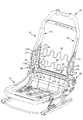
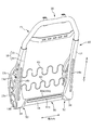
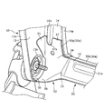
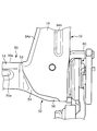
- FIG. 1 is an overall view of a vehicle seat. It is a figure which shows the seat frame containing the seat back frame which concerns on one Embodiment of this invention. It is a back perspective view of a seat back frame concerning one embodiment of the present invention. It is a figure when the width direction edge part of the seat back frame which concerns on one Embodiment of this invention is seen from diagonally forward. It is a perspective view of the lower member frame concerning one embodiment of the present invention. It is a figure when the width direction edge part of the seat back frame which concerns on one Embodiment of this invention is seen from back. It is a figure which shows the seat frame containing the seat back frame which concerns on other embodiment of this invention. It is a figure when the width direction edge part of the seat back frame which concerns on other embodiment of this invention is seen from diagonally forward. It is a perspective view of the lower member frame concerning other embodiments of the present invention.
- the “front-rear direction” means the front-rear direction of the vehicle seat, and specifically corresponds to the direction in which the vehicle travels.
- the “width direction” means the width direction (left-right direction) of the vehicle seat, and is the direction that matches the width direction of the seat back of the vehicle seat.
- the seat S includes a seat back S1, a seat cushion S2, and a headrest S3.
- the seat back S1 and the seat cushion S2 are configured by placing the pad material P on the seat frame illustrated in FIGS. 2 and 3 and covering the surface of the pad material P with the skin material W.
- the seat frame constituting the skeleton of the seat S includes a seat back frame F1 included in the seat back S1 and a seat cushion frame F2 included in the seat cushion S2, as shown in FIG. Further, the lower end portion of the seat back frame F1 is connected to the rear end portion of the seat cushion frame F2 via the reclining device 80.
- the seat back frame F1 forms a square frame when the seat frame F is viewed from the front. Further, the seat back frame F1 according to the present embodiment is lighter than a conventional general seat back frame.
- a material that is lighter than a material used for a conventional seat back frame is used as a material that constitutes the seat back frame F1 (for example, a steel plate that constitutes a side frame 10 described later).
- the components constituting the seat back frame F1 are fastened and connected by laser welding without using fasteners such as bolts, nuts, and screws.
- the seat back frame F1 includes a side frame 10, an upper frame 30, and a lower member frame 50 as shown in FIGS.
- a pair of side frames 10 is provided at the end of the seat back frame F1 in the width direction, and is spaced apart in the width direction.
- the upper frame 30 is a frame that connects the upper ends of each of the pair of side frames 10.
- the lower member frame 50 corresponds to a communication frame, and is a frame that connects the lower ends of each of the pair of side frames 10.
- an S spring 60 is installed between the side frames 10 to support the back of the occupant.
- each side frame will be described in detail. Since the pair of left and right side frames 10 have a symmetrical structure, only the structure of one side frame 10 will be described below.
- Each side frame 10 has a spindle-like outer shape when viewed from the side, and its front end portion is curved so as to swell in an arc from an intermediate position in the vertical direction.
- the side frame 10 is constituted by a thin steel plate (ultra high strength steel plate) having a thickness of 1 mm or less.
- Each side frame 10 has a side wall 13 and a rear wall 14 as shown in FIGS.
- the side wall 13 is a portion located on the outermost side in the width direction in the side frame 10 and forms an end portion on the outer side in the width direction of the seat back S1. Further, as shown in FIG. 4, a circular hole is formed in the lower portion of the side wall 13 as the attachment hole 13 b of the reclining device 80.
- the reclining device 80 is attached to the side wall 13 in a state where the reclining shaft 81 is inserted into the attachment hole 13b.
- a flange portion (hereinafter referred to as a front flange portion 13 a) is formed at the front end portion of the side wall 13.
- the front flange portion 13a corresponds to a side wall flange portion, and is formed by bending a front end portion of a thin steel plate constituting the side wall 13 in a substantially right angle toward the inner side in the width direction.
- the front flange portion 13a is formed in a wide range from the center portion to the lower end portion of the side wall 13 in the vertical direction.
- the side wall 13 is formed with a plurality of through holes. These through holes function as other member attachment holes, and are formed for attaching accessory devices such as side airbags (not shown) (strictly, clips for attaching an inflator and a bundling).
- accessory devices such as side airbags (not shown) (strictly, clips for attaching an inflator and a bundling).
- the steel sheet constituting the side wall 13 is subjected to uneven processing for the purpose of increasing rigidity. That is, as shown in FIG. 2 and FIG. 3, the side wall 13 is formed with a convex portion 13c and a concave portion 13d.
- the convex portion 13c is a portion of the side wall 13 where the outer surface is located on the outer side in the width direction (intelligibly, a portion protruding from the concave portion 13d).
- the concave portion 13d is a portion where the outer surface is located on the inner side in the width direction (intelligibly, a depressed portion).
- the convex portion 13c is arranged along the outer edge of the side wall 13 as shown in FIG.
- a part of the convex portion 13 c extends from the front end of the side wall 13 toward the rear end.
- a part of the convex portion 13c is surrounded by the concave portion 13d and formed in a floating island shape, and extends linearly from the rear end of the side wall 13 toward the front end.
- the recess 13d is disposed so as to extend from the lower end of the side wall 13 to a substantially central position of the side wall 13, and is disposed in a substantially C shape as shown in FIG. 3 in the present embodiment.
- the rear wall 14 is a portion provided so as to be orthogonal to the side wall 13, and extends inward in the width direction from the rear end of the side wall 13 as shown in FIGS. 2 and 3. Further, the rear wall 14 extends long in the up-down direction, and the lower end portion of the rear wall 14 turns forward while being curved in an arc shape and is connected to the front flange portion 13a as shown in FIG. That is, the lower end portion of the rear wall 14 corresponds to a portion constituting the bottom surface of the side frame 10, and the upper end surface of the lower end portion that wraps forward forms the bottom surface of the side frame 10. Yes.
- a portion of the rear wall 14 extending from the upper end position to the midway position in the vertical direction has a rectangular shape as shown in FIGS.
- a portion of the rear wall 14 located below the midway position is widened as shown in FIGS.
- a flange portion (hereinafter referred to as an inner flange portion 14a) is formed at the inner end of the rear wall 14 in the width direction.
- the inner flange portion 14a corresponds to the rear wall side flange portion, and is formed by bending the end portion on the inner side in the width direction of the thin steel plate constituting the rear wall 14 toward the front at a substantially right angle.
- the inner flange portion 14a is formed in a wide range from the upper end portion to the lower end portion of the rear wall 14 in the vertical direction, but avoids interference with the lower member frame 50 attached to the lower end portion of the rear wall 14. For reasons, it is interrupted at a position directly above the lower member frame 50. More specifically, the inner flange portion 14 a is formed along an edge line on the inner side in the width direction of the rear wall 14, and bends along the width direction at a position immediately above the lower member frame 50. Further, the inner flange portion 14a slightly extends inward in the width direction from the bent portion, and is interrupted at that position.
- the rear wall 14 is formed with a bead (hereinafter referred to as a reinforcement bead 14b) formed so as to extend in the vertical direction.
- This reinforcement bead 14b consists of a raised part formed by denting a predetermined part of the rear surface of the rear wall 14 forward.
- the reinforcing bead 14b is formed relatively long from the position slightly above the center position of the rear wall 14 in the vertical direction, and the lower end thereof is near the lower end portion of the rear wall 14 (specifically, Is slightly higher than the height at which the reclining device 80 is attached. Further, the reinforcing beads 14 b are formed at the end portions closer to the side walls 13 (that is, the outer end portions) among the both ends in the width direction of the rear wall 14.
- the lower member frame 50 is made of a metal plate-like member extending long in the width direction as shown in FIG. 5, and is formed by processing and molding the plate-like member into a predetermined shape. . Further, as shown in FIG. 2, the lower member frame 50 that is laid between the lower ends of the side frames 10 is positioned behind the reclining shaft 81 that is also laid between the lower ends of the side frames 10. It becomes like this.
- the lower member frame 50 includes a width direction center portion 51, a width direction end portion 52, and a step 53 formed at a boundary position between the width direction center portion 51 and the width direction end portion 52. It is divided into and.
- the lower member frame 50 includes a flange portion (hereinafter, referred to as a flange portion 50a of the lower member frame 50) formed by bending the upper end portion thereof at a substantially right angle toward the front.
- a flange portion 50a of the lower member frame 50 formed by bending the upper end portion thereof at a substantially right angle toward the front.
- the central portion 51 in the width direction of the lower member frame 50 is located between the rear walls 14 of the side frames 10 when the lower member frame 50 is assembled to each of the pair of side frames 10. It is a part to be located. Further, a flange portion 50 a of the lower member frame 50 is provided at the upper end portion of the center portion 51 in the width direction.
- a bead (hereinafter referred to as a reinforcement bead 51a) formed so as to extend along the width direction is formed in the center portion 51 in the width direction.
- the reinforcing bead 51a is composed of a raised portion formed by recessing a predetermined portion of the rear surface of the central portion 51 in the width direction toward the front, and corresponds to a second raised portion of the present invention.
- the reinforcing bead 51a is formed at a substantially central position of the central portion 51 in the width direction in the vertical direction.
- the reinforcing bead 51a is formed long along the width direction, and both ends of the reinforcing bead 51a are near the step 53 (that is, near the boundary position between the width direction central portion 51 and the width direction end portion 52). Has reached.
- the width direction end portion 52 of the lower member frame 50 has the same structure on one end side and the other end side.
- a contact portion 54, a second contact portion 55, and a continuous portion 56 to be described later are provided. It is provided at both the end on one end side and the end on the other end side. For this reason, below, the content of the edge part of one end side is demonstrated as a structure of the width direction edge part 52.
- the width direction end portion 52 of the lower member frame 50 is in contact with the corresponding side frame 10 in a state where the lower member frame 50 is assembled to each of the pair of side frames 10. It is joined.
- the corresponding side frame 10 is a side frame 10 located closer to one of the pair of side frames 10.
- the width direction end portion 52 includes a contact portion 54 that contacts the front surface of the rear wall 14 of the side frame 10 and a second contact surface that contacts the inner surface of the side wall 13 of the side frame 10.
- a contact portion 55 Furthermore, the width direction edge part 52 has the continuous part 56 which follows the lower part of the contact part 54 in the front-back direction, as shown in the figure.
- the abutting portion 54 extends in the vertical direction along the rear wall 14 of the corresponding side frame 10, and the upper end position thereof is located above the upper end position of the width direction central portion 51. Similarly, the lower end position of the contact portion 54 is located below the lower end position of the width direction central portion 51. That is, the vertical length of each of the width direction both ends of the lower member frame 50 is longer than the vertical length of the width direction center portion 51.
- the configuration of the contact portion 54 will be described more specifically.
- the contact portion 54 includes an upper extension portion 57 that forms an upper portion of the contact portion 54 and a lower extension that forms a lower portion of the contact portion 54. And an exit 58.
- the upper extending portion 57 is a portion that extends upward along the rear wall 14 of the corresponding side frame 10, and strictly speaking, is a portion that is located above the widthwise central portion 51 in the vertical direction. .
- the upper extending portion 57 has a hem-extended shape, and the edge line on the inner side in the width direction of the upper extending portion 57 is the edge of the lower end portion of the rear wall 14 in a state where the upper extending portion 57 is in contact with the lower end portion of the rear wall 14.
- the upper extension portion 57 extends to a position where the upper end portion reaches the lower end portion of the reinforcing bead 14 b formed on the rear wall 14.
- a semi-elliptical cutout 57a shown in FIG. 5 is formed at the upper end of the upward extension 57.
- This notch 57a corresponds to the engaging portion of the present invention, and when the lower member frame 50 is assembled to the side frame 10, the lower end portion of the reinforcing bead 14b enters the notch 57a so that the reinforcing bead 14b Engage with the lower end.
- the contact area between the rear wall 14 of the side frame 10 and the contact portion 54 is increased by extending the contact portion 54 upward.
- a reinforcing bead 14 b is formed on the rear wall 14. Thereby, the rigidity of the rear wall 14 is effectively ensured.
- a notch 57a for engaging with the lower end of the reinforcing bead 14b is formed at the upper end of the upward extension 57 in the contact portion 54. The formation of the cutout 57a effectively avoids interference between the reinforcing bead 14b and the upward extending portion 57.
- the width direction end portion 52 of the lower member frame 50 appropriately does not impair the reinforcing effect of the reinforcing bead 14b (in other words, without shortening the reinforcing bead 14b). And is joined to the rear wall 14.
- the notch 57a contacts the rear wall 14 of the side frame 10 in the width direction end portion 52 (strictly, the contact portion 54) when the lower member frame 50 is assembled to the side frame 10. Functions as a positioning hole. That is, by inserting (fitting) the lower end portion of the reinforcing bead 14b into the notch 57a, the contact portion 54 comes into contact with a predetermined portion in the rear wall 14 appropriately.
- the downward extending portion 58 is a portion extending downward along the rear wall 14 of the corresponding side frame 10 and is a portion positioned below the central portion 51 in the width direction in the vertical direction. Further, the downward extending portion 58 extends forward while curving in an arc shape along the lower end portion of the rear wall 14 so as to make good contact with the lower end portion of the rear wall 14. That is, the downward extending portion 58 reaches the lower end portion of the corresponding side frame 10 and extends along the bottom surface of the side frame 10 formed by the lower end portion. Thereby, since the contact area of the rear wall 14 and the contact part 54 of the side frame 10 further increases, the rigidity of the rear wall 14 is further improved.
- the downward extension part 58 becomes narrow as it goes to the front. Moreover, although the downward extension part 58 is piled up on the lower end part of the rear wall 14, you may protrude outside the width direction rather than the rear wall 14. FIG.
- the second contact portion 55 is a portion (protruding portion) protruding forward in a state along the side wall 13 of the corresponding side frame 10. Further, the second contact portion 55 has a substantially triangular shape when viewed from the side, and intersects with the upper extension portion 57 in the contact portion 54 (substantially orthogonal) as shown in FIGS. 4 and 5. ) Is adjacent to the upward extension 57. In other words, in the width direction end portion 52 of the lower member frame 50, the upper portion provided with the upper extension portion 57 and the second contact portion 55 is bent in a substantially right angle on the outer side in the width direction. It is in. Thereby, the rigidity of the upward extension part 57 and the 2nd contact part 55 is improved effectively.
- the second contact portion 55 is disposed at a position adjacent to the portion where the notch 57a is formed in the upper extension portion 57 in the vertical direction. Adjacent to the upper extension 57 at the position. As a result, it is possible to suppress a decrease in the rigidity of the upward extending portion 57 due to the formation of the notch 57a.
- the continuous portion 56 is a portion that is continuous with the lower portion of the contact portion 54 in the front-rear direction (specifically, the front end portion of the downward extending portion 58).
- the continuous portion 56 is curved in an arcuate shape. It extends to.
- the front flange portion 13a and the continuous portion 56 provided on the outer edge portion (strictly, the front end portion) of the side wall 13 of the side frame 10 are in the vertical direction. They are overlapping. More specifically, the continuous portion 56 is placed on the lower end portion of the front flange portion 13a as shown in FIG.
- the continuous portion 56 is laser-welded to the front flange portion 13a in a state of being overlapped with the front flange portion 13a. Thereby, the rigidity of the continuous portion 56 is ensured, and as a result, the rigidity of the entire width direction end portion 52 of the lower member frame 50 is improved.
- the continuous part 56 which concerns on this embodiment is extended until the front-end
- the step 53 is formed by bending the lower member frame 50 in a lightning-like shape at an intermediate position in the width direction. That is, the step 53 corresponds to a bent portion of the lower member frame 50. Further, the step 53 is formed in the lower member frame 50 at a position on the outer side in the width direction with respect to the reinforcing bead 51 a, strictly, at a boundary position between the width direction central portion 51 and the width direction end portion 52. In the present embodiment, the position where the step 53 is formed substantially coincides with the end position on the inner side in the width direction of the rear wall 14 of the side frame 10.
- the lower member frame 50 is bent at an intermediate position in the width direction, and the step 53 is formed in the lower member frame 50.
- a portion located inward in the width direction with respect to the step 53 in the lower member frame 50 in which the step 53 is formed (that is, the central portion 51 in the width direction). ) Is positioned in front of the upward extending portion 57 in the contact portion 54.
- the central portion 51 in the width direction when the central portion 51 in the width direction is positioned further forward, the rear portion of the seat S (strictly, the portion where the lower member frame 50 is positioned) is positioned further forward. Become. Thereby, the space
- the flange portion 50a of the lower member frame 50 is formed long along the width direction at the upper end portion of the lower member frame 50.
- the flange portion 50a includes a portion (hereinafter referred to as a flange center portion 50x) provided in the width direction center portion 51 of the lower member frame 50, a portion (hereinafter referred to as a flange end portion 50y) that is applied to the width direction end portion 52, and Have
- the flange center portion 50x extends along the width direction and is formed over the entire width direction center portion 51 of the lower member frame 50.
- the flange end portion 50 y is formed in an upward extending portion 57 in the contact portion 54 in the width direction end portion 52 of the lower member frame 50. More specifically, the flange end portion 50y is formed obliquely along the edge line on the inner side in the width direction of the upward extending portion 57.
- the flange portion 50a of the lower member frame 50 is formed up to the position reaching the upward extension portion 57, and the flange end portion 50y reaches the upward extension portion 57 of the flange portion 50a. The part is made.
- the flange end portion 50y will be described in more detail. As shown in FIG. 4, the flange end portion 50y is a portion protruding toward the front (second protruding portion), and the second contact portion 55 in the width direction. It is formed in the position facing. The flange end portion 50 y is adjacent to the second extending portion 55 on the opposite side to the upper extending portion 57 in the contacting portion 54. In other words, in the width direction end portion 52 of the lower member frame 50, the upper portion provided with the upper extension portion 57 and the flange end portion 50y is in a state where the width direction inner side is bent at a substantially right angle. Thereby, the rigidity of the upward extension part 57 is improved further effectively.
- the flange end portion 50y is formed so as to reach the formation position of the notch 57a in the upward extending portion 57 in the vertical direction. As a result, it is possible to more effectively suppress a decrease in the rigidity of the upward extending portion 57 due to the formation of the notch 57a.
- the flange end portion 50y faces the inner flange portion 14a provided on the rear wall 14 of the side frame 10 in the width direction. is doing. More specifically, the flange end portion 50y is arranged along a portion adjacent to the upward extending portion 57 in the inner flange portion 14a. Thereby, the reinforcing effect by the inner flange portion 14 a is further enhanced by the flange portion 50 a of the lower member frame 50.
- a slight gap is formed between the flange end portion 50y and a portion adjacent to the upper extension portion 57 in the inner flange portion 14a. Further, the flange end portion 50y and the portion adjacent to the upper extending portion 57 in the inner flange portion 14a are both inclined so as to descend toward the inner side in the width direction, and bent at the lowermost portion thereof. Then, it extends slightly linearly inward in the width direction.
- FIG. 7 is a view showing a seat frame including a seat back frame F1 according to a modification, and corresponds to FIG.
- FIG. 8 is a view of the end portion in the width direction of the seat back frame F1 according to the modification when viewed obliquely from the front, and corresponds to FIG.
- FIG. 9 is a perspective view of a lower member frame 50 according to a modification, and corresponds to FIG.
- the abutting portion 54 has a width from the outer end in the width direction.
- a substantially fan-shaped notch (hereinafter referred to as fan-shaped notch 59) is formed inward in the width direction.
- the fan-shaped notch 59 is formed at a substantially central portion of the contact portion 54 in the vertical direction.
- the fan-shaped notch 59 is formed for the purpose of weight reduction and is therefore somewhat wider (in other words, the opening width is somewhat longer in the vertical direction).
- the fan-shaped notch 59 is blocked by the rear wall 14 located on the rear side of the fan-shaped notch 59.
- the rear wall 14 of each of the pair of side frames 10 covers the fan-shaped notch 59 provided in the contact portion 54 located in front of the rear wall 14 from the rear.
- the entire fan-shaped notch 59 is covered by the rear wall 14 of the side frame 10.
- the present invention is not limited to this, and at least a part of the fan-shaped notch 59 is used. May be covered by the rear wall 14.
- the outer edge portion of the fan-shaped notch 59 is bent forward to form a flange portion (hereinafter, the flange portion 50b around the notch).
- the flange portion 50b By forming the flange portion 50b around the notch, it is possible to more effectively suppress the lowering of the rigidity of the lower member frame 50 due to the formation of the fan-shaped notch 59.
- the fan-shaped notch 59 is positioned below the reinforcing bead 14b provided on the rear wall 14 of the side frame 10 in the vertical direction as shown in FIG. It exists in the position along with the reinforcement bead 51a provided in the center part 51.
- FIG. Further, the fan-shaped notch 59 is located outside the reinforcing bead 51a provided in the central portion 51 in the width direction in the width direction, and extends downward from the lower end of the reinforcing bead 14b provided in the rear wall 14 along the vertical direction.
- a virtual line (indicated by a broken line in FIG. 8) is at a position where it passes.
- the reinforcement beads 14b and 51a are arranged around the fan-shaped notch 59, so that the rigidity around the fan-shaped notch 59 is appropriately ensured.
- the configuration of the contact portion 54 will be described again.
- the upper extension portion 57 that forms the upper portion of the contact portion 54 and the lower extension portion 58 that forms the lower portion of the contact portion 54. It is equipped with.
- the upper extending portion 57 is located above the fan-shaped notch 59 in the contact portion 54 and extends upward along the rear wall 14 of the corresponding side frame 10.
- the downward extending portion 58 is located at a position lower than the fan-shaped notch 59 in the contact portion 54 and extends downward along the rear wall 14 of the corresponding side frame 10.
- the upward extending portion 57 is located above the center portion 51 in the width direction of the lower member frame 50 in the vertical direction.
- the downward extension part 58 is located below the width direction center part 51 in the up-down direction.
- the contact portion 54 is provided with the upper extension 57 extending along the rear wall 14 of the side frame 10 above the fan-shaped notch 59. Accordingly, the width direction end portion 52 of the lower member frame 50 is brought into contact with the rear wall 14 of the side frame 10 while part of the contact portion 54 (width direction end portion) is notched for weight reduction. It is possible to appropriately exhibit the effect of improving the rigidity.
- a semi-elliptical cutout 57a is formed at the upper end of the upward extension 57.
- the semi-elliptical cutout 57a is formed by the lower end of the reinforcement bead 14b entering the inside of the semi-elliptical cutout 57a in a state where the lower member frame 50 is assembled to the side frame 10. Engage with the lower end.
- the reinforcing effect of the reinforcing bead 14b is not impaired (which is easy to understand) (Without shortening the reinforcing bead 14b), the end 52 in the width direction of the lower member frame 50 can be appropriately brought into contact with the rear wall 14 of the side frame 10 and joined to the rear wall 14.
Landscapes
- Engineering & Computer Science (AREA)
- Aviation & Aerospace Engineering (AREA)
- Transportation (AREA)
- Mechanical Engineering (AREA)
- Seats For Vehicles (AREA)
- Chair Legs, Seat Parts, And Backrests (AREA)
Abstract
サイドフレームの剛性を確保しつつ、サイドフレームの後壁に連絡フレームを適切に当接させる。 シートバックの幅方向において間隔を空けて設けられた一対のサイドフレーム(10)の各々は、側壁(13)と、側壁(13)の後端部から幅方向内側に延びた後壁(14)と、後壁(14)において上下方向に延出するように形成された補強ビード(14b)を有する。また、一対のサイドフレーム(10)の各々の下端部同士を連絡するロアメンバーフレーム(50)のうちの幅方向端部は、対応するサイドフレーム(10)の後壁(14)に当接する当接部分(54)を有する。そして、当接部分(54)には、後壁(14)に沿って上方に延出した上方延出部(57)と、上方延出部(57)の上端部に形成されており補強ビード(14b)の下端部と係合する切り欠き(57a)と、が設けられている。
Description
本発明は、シートバックフレームに係り、特に、一対のサイドフレームの下端部同士を連絡する連絡フレームを備えるシートバックフレームに関する。
車両用シートのシートバックは、その骨格としてのシートバックフレームを備えている。シートバックフレームの構成としては、一般的にシート幅方向両端部にサイドフレームを備えた構成が知られている。また、シートバックフレームの中には、一対のサイドフレームの各々の下端部同士を連絡する連絡フレームを備えているものがある。この連絡フレームは、例えばロアメンバーフレームとして機能する。すなわち、連絡フレームのシート幅方向両端部がそれぞれ、対応するサイドフレームの後壁に当接することで一対のサイドフレームの下端部同士が連絡されるようになる。
また、連絡フレームを備えたシートバックフレームの中には、特許文献1に示すように、サイドフレームの後壁に当接している連絡フレームのシート幅方向端部が上方に向かって延出しているものがある。このような構成のシートバックフレームによれば、サイドフレームの後壁と連絡フレームとの当接面積がより大きくなるため、当該当接箇所における剛性が高められることとなる。特に、シートバックに後方への荷重が掛かった際にサイドフレームの後壁に作用する力(厳密には圧縮力)に対する剛性が向上するようになる。
また、連絡フレームを備えたシートバックフレームの中には、軽量化等の目的のために、特許文献2に示すように連絡フレームのシート幅方向端部に穴が形成されているものがある。
ところで、上記のようにサイドフレームの剛性を高める構成としては、サイドフレームの後壁に補強ビードのような隆起部を形成することが考えられる。このようにサイドフレームの後壁に隆起部を設ける場合には、効果的に剛性を確保する目的から、当該隆起部を上下方向に沿って長く形成させるのが望ましい。その上で、サイドフレームの後壁には連絡フレームのシート幅方向端部を当接させる際には、上記の隆起部を考慮して適切にサイドフレームの後壁に連絡フレームを当接させることが求められる。
また、特許文献2では連結フレームのシート幅方向端部に穴が形成されていることとしたが、穴の代わりに切り欠きが形成される場合も考えられる。一方で、連絡フレームのシート幅方向端部に切り欠きが形成された場合、当該切り欠きが形成された分だけ、連絡フレームとサイドフレームとの当接面積が減少することになる。そして、当接面積が減少すると、その分だけ、サイドフレームの後壁の剛性を確保し難くなってしまう。
そこで、本発明は、上記の問題に鑑みてなされたものであり、その目的は、サイドフレームの剛性を確保しつつ、サイドフレームの後壁に連絡フレームを適切に当接させることが可能なシートバックフレームを提供することにある。
また、本発明の目的は、連絡フレームのシート幅方向端部に切り欠きを設けながらもサイドフレームの後壁の剛性を適切に確保することが可能なシートバックフレームを提供することにある。
前記課題は、本発明のシートバックフレームによれば、シートバックの幅方向において間隔を空けて設けられた一対のサイドフレームと、該一対のサイドフレームの各々の下端部同士を連絡する連絡フレームと、を備え、前記一対のサイドフレームの各々は、前記幅方向における前記シートバックの両端部をなす側壁と、該側壁の後端部から前記幅方向の内側に延びた後壁と、を有し、該後壁には、上下方向に延出するように形成された隆起部を備えており、前記連絡フレームの前記幅方向における端部は、前記一対のサイドフレームのうち、対応するサイドフレームの前記後壁に当接する当接部分を有し、該当接部分には、前記後壁に沿って上方に延出した上方延出部と、該上方延出部の上端部に形成されており前記隆起部の下端部と係合する係合部と、が設けられていることにより解決される。
以上のように構成されたシートバックフレームでは、シートバックの幅方向(以下、単に幅方向)における連絡フレームの端部のうち、サイドフレームの後壁に当接している当接部分が後壁に沿って上方に延出している。また、サイドフレームの後壁には上下方向に延出した隆起部が形成されている。このような構成により、サイドフレームの後壁の剛性を効果的に確保することが可能となる。さらに、連絡フレームが幅方向端部に有するサイドフレームの後壁との当接部分のうち、後壁に沿って上方に延出した上方延出部の上端部は、隆起部の下端部と係合する係合部が設けられている。そして、係合部に隆起部の下端部が係合した状態で連絡フレームの当接部分がサイドフレームの後壁に当接する。これにより、隆起部の補強効果を損なうことなく、連結フレームをサイドフレームの後壁に適切に当接させることが可能となる。
また、上記のシートバックフレームにおいて、前記連絡フレームの前記幅方向における端部は、前記対応するサイドフレームの前記後壁の前方表面に当接する前記当接部分と、前記対応するサイドフレームの前記側壁に沿った状態で前方に突出した突出部分とを有し、前記当接部分中の前記上方延出部と前記突出部分とは、互いに交差した状態で隣接しているとよい。
上記の構成によれば、連絡フレームの幅方向端部にサイドフレームとの当接部分と前方に突出した突出部分とが設けられている。これにより、サイドフレームの後壁の剛性をより一層高めることが可能となる。
上記の構成によれば、連絡フレームの幅方向端部にサイドフレームとの当接部分と前方に突出した突出部分とが設けられている。これにより、サイドフレームの後壁の剛性をより一層高めることが可能となる。
また、上記のシートバックフレームにおいて、前記連絡フレームの前記幅方向における端部は、前記幅方向において前記突出部分と対向する位置に形成され前方に向かって突出した第二の突出部分を更に有し、該第二の突出部分は、前記突出部分とは反対側で前記当接部分中の前記上方延出部と交差した状態で隣接しているとよい。
上記の構成によれば、連絡フレームの幅方向端部において、サイドフレームとの当接部分と、当該当接部分を挟んで対向する二つの突出部分と、が設けられている。これにより、サイドフレームの後壁の剛性を一段と高めることが可能となる。
上記の構成によれば、連絡フレームの幅方向端部において、サイドフレームとの当接部分と、当該当接部分を挟んで対向する二つの突出部分と、が設けられている。これにより、サイドフレームの後壁の剛性を一段と高めることが可能となる。
また、上記のシートバックフレームにおいて、前記連絡フレームは、板状部材からなり、前記連絡フレームの上端部を前方に向けて折り曲げることで形成されたフランジ部を有しており、該フランジ部は、前記上方延出部に達する位置まで形成されており、前記フランジ部のうち、前記上方延出部に達した部分が前記第二の突出部分を構成しているとよい。
上記の構成によれば、連絡フレームの上端部に形成されたフランジ部が連絡フレームの幅方向端部(より具体的には、サイドフレームとの当接部分のうち、上方延出部)に達している。これにより、サイドフレームの後壁の剛性を益々高めることが可能となる。
上記の構成によれば、連絡フレームの上端部に形成されたフランジ部が連絡フレームの幅方向端部(より具体的には、サイドフレームとの当接部分のうち、上方延出部)に達している。これにより、サイドフレームの後壁の剛性を益々高めることが可能となる。
また、上記のシートバックフレームにおいて、前記フランジ部のうち、前記上方延出部に達した部分は、前記幅方向における前記後壁の内側の端部を前方に向けて折り曲げることで形成された後壁側フランジ部のうち、前記上方延出部と隣り合う部分に沿って並んでいるとよい。
上記の構成によれば、連絡フレームの幅方向端部(より具体的には、サイドフレームとの当接部分のうち、上方延出部)に達したフランジ部と、当該フランジ部と隣り合う位置に設けられたサイドフレームのフランジ部(後壁側フランジ部)とが並んでいる。これにより、サイドフレームのフランジ部による補強効果を連絡フレームのフランジ部によって更に高めることが可能となる。
上記の構成によれば、連絡フレームの幅方向端部(より具体的には、サイドフレームとの当接部分のうち、上方延出部)に達したフランジ部と、当該フランジ部と隣り合う位置に設けられたサイドフレームのフランジ部(後壁側フランジ部)とが並んでいる。これにより、サイドフレームのフランジ部による補強効果を連絡フレームのフランジ部によって更に高めることが可能となる。
また、上記のシートバックフレームにおいて、前記連絡フレームが前記幅方向の中途位置にて屈曲していることにより前記連絡フレームの前記幅方向における中央部が前記当接部分中の前記上方延出部よりも前方に位置しているとよい。
上記の構成によれば、連絡フレームの幅方向中央部がより前方に位置していることから、例えば、後方にある座席に着座する着座者の足元(特に脛部)との間隔を広げて当該足元周りのスペースを確保することが可能となる。
上記の構成によれば、連絡フレームの幅方向中央部がより前方に位置していることから、例えば、後方にある座席に着座する着座者の足元(特に脛部)との間隔を広げて当該足元周りのスペースを確保することが可能となる。
また、上記のシートバックフレームにおいて、前記連絡フレームは、前記幅方向における中央部において前記幅方向に延出するように形成された第二の隆起部を備えているとよい。
上記の構成によれば、第二の隆起部を備えることで連絡フレームの剛性が更に向上するようになる。
上記の構成によれば、第二の隆起部を備えることで連絡フレームの剛性が更に向上するようになる。
また、上記のシートバックフレームにおいて、前記連絡フレームが前記幅方向の中途位置にて屈曲していることにより前記連絡フレームの前記幅方向における中央部が前記当接部分の前記上方延出部よりも前方に位置しており、前記幅方向において前記連絡フレームの屈曲箇所が前記第二の隆起部よりも外側に位置しているとよい。
上記の構成によれば、連絡フレームのうち、第二の隆起部が設けられている部分をより前方に位置させる。これにより、後方にある座席に着座する着座者の足元(特に脛部)との間隔を広げて当該足元周りのスペースを確保することが可能となる。
上記の構成によれば、連絡フレームのうち、第二の隆起部が設けられている部分をより前方に位置させる。これにより、後方にある座席に着座する着座者の足元(特に脛部)との間隔を広げて当該足元周りのスペースを確保することが可能となる。
また、上記のシートバックフレームにおいて、前記連絡フレームの前記幅方向における端部は、前記対応するサイドフレームの前記後壁の前方表面に当接する前記当接部分と、前記対応するサイドフレームの前記側壁の内側面に当接する第二の当接部分とを有し、前記当接部分中の前記上方延出部と前記第二の当接部分とは、互いに交差した状態で隣接しているとよい。
上記の構成によれば、連絡フレームの幅方向端部に設けられた当接部分がサイドフレームの後壁に当接し、同じく幅方向端部に設けられた第二の当接部分がサイドフレームの側壁に当接している。これにより、連絡フレームをサイドフレームに対してより強固に固定することが可能となるとともに、連絡フレームが取り付けられたサイドフレームの下端部の剛性を効率よく確保することが可能となる。
上記の構成によれば、連絡フレームの幅方向端部に設けられた当接部分がサイドフレームの後壁に当接し、同じく幅方向端部に設けられた第二の当接部分がサイドフレームの側壁に当接している。これにより、連絡フレームをサイドフレームに対してより強固に固定することが可能となるとともに、連絡フレームが取り付けられたサイドフレームの下端部の剛性を効率よく確保することが可能となる。
また、上記のシートバックフレームにおいて、前記係合部は、前記上方延出部の上端部に形成された切り欠きであり、該切り欠き内に前記隆起部の下端部が入り込むことにより前記隆起部の下端部と係合するとよい。
上記の構成によれば、連絡フレームの幅方向端部に設けられた当接部分の上方延出部を、サイドフレームの後壁に設けられた隆起部に係合させることが容易となる。また、上記の構成によれば、連絡フレームをサイドフレームの後壁に当接させる際に係合部としての切り欠きを利用することで、サイドフレームの後壁に対して連結フレームの幅方向端部の位置決めを行うことが可能となる。
上記の構成によれば、連絡フレームの幅方向端部に設けられた当接部分の上方延出部を、サイドフレームの後壁に設けられた隆起部に係合させることが容易となる。また、上記の構成によれば、連絡フレームをサイドフレームの後壁に当接させる際に係合部としての切り欠きを利用することで、サイドフレームの後壁に対して連結フレームの幅方向端部の位置決めを行うことが可能となる。
また、上記のシートバックフレームにおいて、前記連絡フレームの前記幅方向における両端部が前記当接部分を有しており、前記連絡フレームの前記幅方向における両端部の各々の上下長さは、前記連絡フレームの前記幅方向における中央部の上下長さよりも長いとよい。
上記の構成によれば、連絡フレームのうち、サイドフレームの後壁と当接する部分をそれ以外の部分よりも幅広にすることで、連絡フレームをサイドフレームにより容易に当接させることが可能となる。これにより、連絡フレームを当接させてサイドフレームの後壁の剛性を高めることが、より容易に実現されるようになる。
上記の構成によれば、連絡フレームのうち、サイドフレームの後壁と当接する部分をそれ以外の部分よりも幅広にすることで、連絡フレームをサイドフレームにより容易に当接させることが可能となる。これにより、連絡フレームを当接させてサイドフレームの後壁の剛性を高めることが、より容易に実現されるようになる。
また、上記のシートバックフレームにおいて、前記当接部分には、前記後壁に沿って下方に延出した下方延出部が更に設けられているとよい。
上記の構成によれば、連絡フレームの幅方向端部に下方延出部が設けられることにより、サイドフレームの後壁と連絡フレームとの当接面積が一段と大きくなるため、サイドフレームの後壁の剛性を更に高めることが可能となる。
上記の構成によれば、連絡フレームの幅方向端部に下方延出部が設けられることにより、サイドフレームの後壁と連絡フレームとの当接面積が一段と大きくなるため、サイドフレームの後壁の剛性を更に高めることが可能となる。
また、上記のシートバックフレームにおいて、前記下方延出部は、前記対応するサイドフレームのうち、底面を構成する部分まで至り当該底面に沿って延出しているとよい。
上記の構成によれば、下方延出部がサイドフレームの底面に沿って延出しているので、サイドフレームの後壁と連絡フレームとの当接面積が更に大きくなるため、サイドフレームの後壁の剛性をより一層高めることが可能となる。
上記の構成によれば、下方延出部がサイドフレームの底面に沿って延出しているので、サイドフレームの後壁と連絡フレームとの当接面積が更に大きくなるため、サイドフレームの後壁の剛性をより一層高めることが可能となる。
また、上記のシートバックフレームにおいて、前記一対のサイドフレームの各々は、前記側壁の外縁部を前記幅方向において外側に折り曲げることで形成された側壁側フランジ部を有し、前記連絡フレームの前記幅方向における端部は、前後方向において前記当接部分と連続する連続部分を有し、該連続部分は、前記対応するサイドフレームの前記側壁に形成された前記側壁側フランジ部と上下方向において重なり合った状態で該側壁側フランジ部に接合されているとよい。
上記の構成によれば、連絡フレームの幅方向端部が当接部分と前後方向において連続する連続部分を備えており、また、当該連続部分がサイドフレームのフランジ部(側壁側フランジ部)と接合されている。これにより、連続部分の剛性が確保され、連絡フレームの幅方向端部全体の剛性が向上することになる。
上記の構成によれば、連絡フレームの幅方向端部が当接部分と前後方向において連続する連続部分を備えており、また、当該連続部分がサイドフレームのフランジ部(側壁側フランジ部)と接合されている。これにより、連続部分の剛性が確保され、連絡フレームの幅方向端部全体の剛性が向上することになる。
また、上記のシートバックフレームにおいて、前記当接部分には、前記幅方向において前記当接部分の外側の端から前記幅方向の内側に向かって形成された切り欠きが設けられており、前記上方延出部は、前記切り欠きよりも上方位置に在り前記後壁に沿って上方に延出しているとよい。
以上の構成では、シートバックの幅方向(以下、単に幅方向)における連絡フレームの端部のうち、サイドフレームの後壁に当接している当接部分に、幅方向内側に向かう切り欠きが形成されている。また、当接部分の上方延出部は、切り欠きよりも上方に在り、サイドフレームの後壁に沿って上方に延出している。このような上方延出部が設けられていることで、上記の切り欠きを形成しながらも、連絡フレームとサイドフレームの後壁との当接面積の減少を抑えることが可能となる。これにより、連絡フレームの幅方向端部に切り欠きを設けながらもサイドフレームの後壁の剛性を適切に確保することが可能となる。
以上の構成では、シートバックの幅方向(以下、単に幅方向)における連絡フレームの端部のうち、サイドフレームの後壁に当接している当接部分に、幅方向内側に向かう切り欠きが形成されている。また、当接部分の上方延出部は、切り欠きよりも上方に在り、サイドフレームの後壁に沿って上方に延出している。このような上方延出部が設けられていることで、上記の切り欠きを形成しながらも、連絡フレームとサイドフレームの後壁との当接面積の減少を抑えることが可能となる。これにより、連絡フレームの幅方向端部に切り欠きを設けながらもサイドフレームの後壁の剛性を適切に確保することが可能となる。
本発明のシートバックフレームによれば、サイドフレームの剛性を確保しつつ、サイドフレームの後壁に連絡フレームを適切に当接させることが可能となる。
また、本発明のシートバックフレームによれば、連絡フレームの幅方向端部にサイドフレームとの当接部分と前方に突出した突出部分とが設けられていることで、サイドフレームの後壁の剛性がより一層高められる。
また、本発明のシートバックフレームによれば、連絡フレームの幅方向端部においてサイドフレームとの当接部分と、当該当接部分を挟んで対向する二つの突出部分と、が設けられていることで、サイドフレームの後壁の剛性が一段と高められる。
また、本発明のシートバックフレームによれば、連絡フレームの上端部に形成されたフランジ部が連絡フレームの幅方向端部(厳密には、サイドフレームとの当接部分の上方延出部)に達していることで、サイドフレームの後壁の剛性が益々高められる。
また、本発明のシートバックフレームによれば、連絡フレームの幅方向端部に達したフランジ部と、当該フランジ部と隣り合う位置に設けられたサイドフレームのフランジ部とが並んでいることで、サイドフレームのフランジ部による補強効果が高められる。
また、本発明のシートバックフレームによれば、連絡フレームの幅方向中央部がより前方に位置することで、後方にある座席に着座する着座者の足元(特に脛部)との間隔が広がり、当該足元周りのスペースが確保される。
また、本発明のシートバックフレームによれば、連絡フレームに第二の隆起部を備えることで連絡フレームの剛性が更に向上する。
また、本発明のシートバックフレームによれば、連絡フレームのうち、第二の隆起部が設けられている部分をより前方に位置させることで、後方にある座席に着座する着座者の足元(特に脛部)との間隔が広がり、当該足元周りのスペースが確保される。
また、本発明のシートバックフレームによれば、連絡フレームの幅方向端部に設けられた当接部分及び第二の当接部分がそれぞれサイドフレームに当接していることで、連絡フレームがサイドフレームに対してより強固に固定され、サイドフレームの下端部の剛性が効率よく確保されるようになる。
また、本発明のシートバックフレームによれば、連絡フレームの幅方向端部に設けられた当接部分の上方延出部に係合部として切り欠きを設けることで、上方延出部をサイドフレームの後壁に設けられた隆起部に係合させることが容易となる。また、連絡フレームをサイドフレームの後壁に当接させる際に上記の切り欠きを利用することで、サイドフレームの後壁に対して連結フレームの幅方向端部の位置決めを行うことが可能となる。
また、本発明のシートバックフレームによれば、連絡フレームのうち、サイドフレームの後壁と当接する部分をそれ以外の部分よりも幅広にすることで、サイドフレームの後壁の剛性をより容易に高めることが可能となる。
また、本発明のシートバックフレームによれば、連絡フレームの幅方向端部に下方延出部が設けられることで、サイドフレームの後壁の剛性が更に高められる。
また、本発明のシートバックフレームによれば、下方延出部がサイドフレームの底面に沿っていることで、サイドフレームの後壁の剛性がより一層高められる。
また、本発明のシートバックフレームによれば、連絡フレームの幅方向端部中、当接部分と前後方向において連続する連続部分の剛性が確保され、連絡フレームの幅方向端部全体の剛性を向上させることが可能となる。
また、本発明のシートバックフレームによれば、連絡フレームの幅方向端部に切り欠きを設けながらもサイドフレームの後壁の剛性を適切に確保することが可能となる。
また、本発明のシートバックフレームによれば、連絡フレームの幅方向端部にサイドフレームとの当接部分と前方に突出した突出部分とが設けられていることで、サイドフレームの後壁の剛性がより一層高められる。
また、本発明のシートバックフレームによれば、連絡フレームの幅方向端部においてサイドフレームとの当接部分と、当該当接部分を挟んで対向する二つの突出部分と、が設けられていることで、サイドフレームの後壁の剛性が一段と高められる。
また、本発明のシートバックフレームによれば、連絡フレームの上端部に形成されたフランジ部が連絡フレームの幅方向端部(厳密には、サイドフレームとの当接部分の上方延出部)に達していることで、サイドフレームの後壁の剛性が益々高められる。
また、本発明のシートバックフレームによれば、連絡フレームの幅方向端部に達したフランジ部と、当該フランジ部と隣り合う位置に設けられたサイドフレームのフランジ部とが並んでいることで、サイドフレームのフランジ部による補強効果が高められる。
また、本発明のシートバックフレームによれば、連絡フレームの幅方向中央部がより前方に位置することで、後方にある座席に着座する着座者の足元(特に脛部)との間隔が広がり、当該足元周りのスペースが確保される。
また、本発明のシートバックフレームによれば、連絡フレームに第二の隆起部を備えることで連絡フレームの剛性が更に向上する。
また、本発明のシートバックフレームによれば、連絡フレームのうち、第二の隆起部が設けられている部分をより前方に位置させることで、後方にある座席に着座する着座者の足元(特に脛部)との間隔が広がり、当該足元周りのスペースが確保される。
また、本発明のシートバックフレームによれば、連絡フレームの幅方向端部に設けられた当接部分及び第二の当接部分がそれぞれサイドフレームに当接していることで、連絡フレームがサイドフレームに対してより強固に固定され、サイドフレームの下端部の剛性が効率よく確保されるようになる。
また、本発明のシートバックフレームによれば、連絡フレームの幅方向端部に設けられた当接部分の上方延出部に係合部として切り欠きを設けることで、上方延出部をサイドフレームの後壁に設けられた隆起部に係合させることが容易となる。また、連絡フレームをサイドフレームの後壁に当接させる際に上記の切り欠きを利用することで、サイドフレームの後壁に対して連結フレームの幅方向端部の位置決めを行うことが可能となる。
また、本発明のシートバックフレームによれば、連絡フレームのうち、サイドフレームの後壁と当接する部分をそれ以外の部分よりも幅広にすることで、サイドフレームの後壁の剛性をより容易に高めることが可能となる。
また、本発明のシートバックフレームによれば、連絡フレームの幅方向端部に下方延出部が設けられることで、サイドフレームの後壁の剛性が更に高められる。
また、本発明のシートバックフレームによれば、下方延出部がサイドフレームの底面に沿っていることで、サイドフレームの後壁の剛性がより一層高められる。
また、本発明のシートバックフレームによれば、連絡フレームの幅方向端部中、当接部分と前後方向において連続する連続部分の剛性が確保され、連絡フレームの幅方向端部全体の剛性を向上させることが可能となる。
また、本発明のシートバックフレームによれば、連絡フレームの幅方向端部に切り欠きを設けながらもサイドフレームの後壁の剛性を適切に確保することが可能となる。
以下、本発明の一実施形態(本実施形態)について説明する。ただし、以下に説明する実施形態は、本発明の理解を容易にするための一例に過ぎず、本発明を限定するものではない。すなわち、本発明は、その趣旨を逸脱することなく、変更、改良され得ると共に、本発明にはその等価物が含まれることは勿論である。また、以下の説明中、各機器及びその構成部品の材質、形状及びサイズに関する内容は、あくまでも具体例の一つに過ぎず、本発明を限定するものではない。すなわち、各機器及びその構成部品の材質、形状及びサイズについては、本発明の特定事項を満たすものである限り自由に設計することが可能である。
また、以下の説明において「前後方向」とは、車両用シートの前後方向を意味し、具体的には車両の走行方向と一致する方向である。また、「幅方向」とは、車両用シートの幅方向(左右方向)を意味し、車両用シートが有するシートバックの幅方向と一致する方向である。
先ず、本実施形態に係るシートバックフレームF1を利用した車両用シート(以下、本シートS)の基本構成について図1乃至3を参照しながら基本構成を説明する。本シートSは、図1に示すように、シートバックS1、シートクッションS2及びヘッドレストS3を有する。シートバックS1及びシートクッションS2は、それぞれの図2や図3に図示のシートフレームにパッド材Pを載置して同パッド材Pの表面を表皮材Wで覆うことによって構成されている。
本シートSの骨格をなすシートフレームは、図2に示すように、シートバックS1が有するシートバックフレームF1、及び、シートクッションS2が有するシートクッションフレームF2を有する。また、シートバックフレームF1の下端部は、リクライニング装置80を介してシートクッションフレームF2の後端部に連結されている。
次に、シートバックフレームF1の詳細構成について図2乃至図6を参照しながら説明する。
シートバックフレームF1は、図2に示すように、シートフレームFを前方から見たときに方形枠をなしている。また、本実施形態に係るシートバックフレームF1は、従来の一般的なシートバックフレームと比較して軽量化されたものとなっている。
シートバックフレームF1は、図2に示すように、シートフレームFを前方から見たときに方形枠をなしている。また、本実施形態に係るシートバックフレームF1は、従来の一般的なシートバックフレームと比較して軽量化されたものとなっている。
具体的に説明すると、シートバックフレームF1を構成する材料(例えば、後述するサイドフレーム10を構成する鋼板)として、従来のシートバックフレームに用いられていた材料よりも軽量な材料が用いられている。さらに、シートバックフレームF1を構成する部品同士については、ボルト・ナットやビス等の締結具を使用せず、レーザ溶接にて部品同士が締結・連結されている。
また、本実施形態に係るシートバックフレームF1は、図2及び図3に示すようにサイドフレーム10とアッパフレーム30とロアメンバーフレーム50とを有する。サイドフレーム10は、幅方向におけるシートバックフレームF1の端部をなし、幅方向において間隔を空けて一対設けられている。アッパフレーム30は、一対のサイドフレーム10の各々の上端部同士を連絡するフレームである。ロアメンバーフレーム50は、連絡フレームに相当し、一対のサイドフレーム10の各々の下端部同士を連結するフレームである。さらに、サイドフレーム10の間には、乗員の背を支持するSバネ60が架設されている。
次に、各サイドフレームについて詳細に説明する。左右一対のサイドフレーム10は、左右対称の構造となっているため、以下では、一方のサイドフレーム10の構造のみを説明することとする。
各サイドフレーム10は、側方視で紡錘状の外形形状をなしており、その前端部分が上下方向の中途位置から円弧状に膨らむように湾曲している。なお、本実施形態では、厚み1mm以下の薄厚の鋼板(超高張力鋼板)によってサイドフレーム10が構成されている。また、各サイドフレーム10は、図2及び図3に示すように側壁13及び後壁14を有している。
側壁13は、サイドフレーム10中、幅方向において最も外側に位置する部分であり、シートバックS1の幅方向外側の端部をなしている。また、図4に示すように、側壁13の下部には、リクライニング装置80の取り付け穴13bとしての円穴が形成されている。リクライニング装置80は、この取り付け穴13b内にリクライニング軸81が挿通された状態で側壁13に取り付けられている。
また、側壁13の前端部には図2や図4に示すようにフランジ部(以下、前方フランジ部13a)が形成されている。この前方フランジ部13aは、側壁側フランジ部に相当し、側壁13を構成する薄厚鋼板の前端部を幅方向内側に向けて略直角に折り曲げることで形成されている。なお、前方フランジ部13aは、上下方向において側壁13の中央部から下端部に亘って広範囲に形成されている。
また、本実施形態では、図2や図3に示すように、側壁13には貫通孔が複数箇所に形成されている。これらの貫通孔は、他部材取り付け孔として機能し、不図示のサイドエアバッグ(厳密には、インフレータや力布取り付け用のクリップ)等の付属機器を取り付けるために形成されている。
また、側壁13を構成している鋼板に対しては、剛性を高める目的により凹凸加工が施されている。すなわち、図2や図3に示すように、側壁13には凸部13c及び凹部13dが形成されている。ここで、凸部13cとは、側壁13中、外表面がより幅方向外側に位置している部分(分かり易くは、凹部13dに対して突出した部分)である。凹部13dとは、外表面がより幅方向内側に位置している部分(分かり易くは、窪んだ部分)である。
なお、本実施形態おいて、凸部13cは、図3に示すように側壁13の外縁に沿って配置されている。また、凸部13cの一部分は、側壁13の前端から後端に向かって延出している。さらに、凸部13cの一部分は、その周囲が凹部13dに囲まれて浮島状に形成されており、側壁13の後端から前端に向かって線状に延出している。凹部13dは、側壁13の下端から側壁13の略中央位置まで延出するように配置されており、本実施形態では図3に示すように略C字状に配置されている。
後壁14は、側壁13に対して直交するように設けられた部分であり、図2及び図3に示すように側壁13の後端部から幅方向内側に向かって延出している。また、後壁14は、上下方向に長く延びており、その下端部は、図4に示すように、円弧状に湾曲しながら前方に回り込んで前方フランジ部13aに繋ぎ込まれている。つまり、後壁14の下端部は、サイドフレーム10の底面を構成する部分に相当しており、当該下端部のうち、前方に回り込んでいる部分の上端面がサイドフレーム10の底面をなしている。
なお、後壁14のうち、上下方向において上端位置から中途位置に亘る部分は、図2及び図3に示すように矩形状となっている。これに対し、後壁14のうち、上記の中途位置よりも下方に位置する部分は、図2及び6に示すように裾広がり状となっている。
また、後壁14の幅方向内側の端部には図4に示すようにフランジ部(以下、内側フランジ部14a)が形成されている。この内側フランジ部14aは、後壁側フランジ部に相当し、後壁14を構成する薄厚鋼板の幅方向内側の端部を前方に向けて略直角に折り曲げることで形成されている。
なお、内側フランジ部14aは、上下方向において後壁14の上端部から下端部に亘って広範囲に形成されているが、後壁14の下端部に取り付けられたロアメンバーフレーム50との干渉を避ける理由からロアメンバーフレーム50の直上位置で途切れている。より詳しく説明すると、内側フランジ部14aは、後壁14の幅方向内側の縁線に沿って形成されており、ロアメンバーフレーム50の直上位置で幅方向に沿うように屈曲する。さらに、内側フランジ部14aは、上記の屈曲箇所より幅方向内側に向かって若干延出し、その位置にて途切れている。
また、図3及び図4に示すように、後壁14には上下方向に沿って延出するように形成されたビード(以下、補強ビード14b)が形成されている。この補強ビード14bは、後壁14の後面の所定部位を前方に向かって窪ませることで形成された隆起部からなる。なお、本実施形態において、補強ビード14bは、上下方向において後壁14の中央位置よりもやや上方位置から比較的長く形成されており、その下端は、後壁14の下端部付近(具体的にはリクライニング装置80が取り付けられている高さよりも若干上方)に至っている。また、補強ビード14bは、後壁14の幅方向両端部のうち、側壁13により近い端部(すなわち、外側の端部)に形成されている。
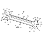
次に、ロアメンバーフレーム50について詳細に説明する。ロアメンバーフレーム50は、ロアメンバーフレーム50は、図5に示すように幅方向に長く延びた金属製の板状部材からなり、当該板状部材を所定形状に加工成形することで形成されている。また、サイドフレーム10の下端部間に架設された状態にあるロアメンバーフレーム50は、図2に示すように、同じくサイドフレーム10の下端部間に架設されたリクライニング軸81よりも後方に位置するようになる。
ロアメンバーフレーム50の構成について説明すると、ロアメンバーフレーム50は、幅方向中央部51と、幅方向端部52と、幅方向中央部51及び幅方向端部52の境界位置に形成された段差53とに分かれている。また、ロアメンバーフレーム50は、その上端部を前方に向かって略直角に折り曲げることで形成されたフランジ部(以下、ロアメンバーフレーム50のフランジ部50a)を備えている。以下、ロアメンバーフレーム50各部について詳しく説明する。
ロアメンバーフレーム50の幅方向中央部51は、図2及び図3に示すように、ロアメンバーフレーム50が一対のサイドフレーム10の各々に組み付けられた状態においてサイドフレーム10の後壁14の間に位置する部分である。また、幅方向中央部51の上端部には、ロアメンバーフレーム50のフランジ部50aが設けられている。
さらに、図2及び図5に示すように、幅方向中央部51には幅方向に沿って延出するように形成されたビード(以下、補強ビード51a)が形成されている。この補強ビード51aは、幅方向中央部51の後面の所定部位を前方に向かって窪ませることで形成された隆起部からなり、本発明の第二の隆起部に相当する。なお、本実施形態において、補強ビード51aは、上下方向において幅方向中央部51の略中央位置に形成されている。また、補強ビード51aは、幅方向に沿って長く形成されており、当該補強ビード51aの両端は、段差53付近(すなわち、幅方向中央部51と幅方向端部52との境界位置付近)に達している。
ロアメンバーフレーム50の幅方向端部52は、一端側及び他端側でそれぞれ同様の構造となっており、例えば、後述する当接部分54、第二の当接部分55及び連続部分56については一端側の端部及び他端側の端部の双方に備えられている。このため、以下では、幅方向端部52の構造として一端側の端部の内容を説明することとする。
ロアメンバーフレーム50の幅方向端部52は、図2乃至図4に示すように、ロアメンバーフレーム50が一対のサイドフレーム10の各々に組み付けられた状態において、対応するサイドフレーム10と当接して接合している。ここで、対応するサイドフレーム10とは、一対のサイドフレーム10のうち、より近くに位置するサイドフレーム10のことである。
また、幅方向端部52は、図4に示すように、サイドフレーム10の後壁14の前方表面に当接する当接部分54と、サイドフレーム10の側壁13の内側面に当接する第二の当接部分55とを有する。さらに、幅方向端部52は、同図に示すように、前後方向において当接部分54の下方部分と連続する連続部分56を有する。
当接部分54は、対応するサイドフレーム10の後壁14に沿った状態で上下方向に延出しており、その上端位置は、幅方向中央部51の上端位置よりも上方に位置している。同様に、当接部分54の下端位置は、幅方向中央部51の下端位置よりも下方に位置している。すなわち、ロアメンバーフレーム50の幅方向両端部の各々の上下長さは、幅方向中央部51の上下長さよりも長くなっている。
当接部分54の構成についてより具体的に説明すると、当接部分54には、当該当接部分54の上方部分をなす上方延出部57と、当該当接部分54の下方部分をなす下方延出部58と、が設けられている。上方延出部57は、対応するサイドフレーム10の後壁14に沿って上方に延出した部分であり、厳密に説明すると、上下方向において幅方向中央部51よりも上方に位置する部分である。
また、上方延出部57は、裾広がり状になっており、後壁14の下端部に当接した状態では上方延出部57の幅方向内側の縁線が後壁14の下端部の縁線と沿っている。さらに、図2及び図4に示すように、上方延出部57は、その上端部が後壁14に形成された補強ビード14bの下端部に差し掛かる位置まで延出している。そしてまた、上方延出部57の上端部には、図5に図示した半楕円状の切り欠き57aが形成されている。この切り欠き57aは、本発明の係合部に相当し、ロアメンバーフレーム50がサイドフレーム10に組み付けられた状態では切り欠き57a内に補強ビード14bの下端部が入り込むことで当該補強ビード14bの下端部と係合している。
以上のように本実施形態では、当接部分54を上方に延ばすことでサイドフレーム10の後壁14と当接部分54(換言すると、ロアメンバーフレーム50)との当接面積を増加させる。また、後壁14には補強ビード14bが形成されている。これにより、後壁14の剛性が効果的に確保されている。さらに、当接部分54中の上方延出部57の上端部には、補強ビード14bの下端部と係合させるための切り欠き57aが形成されている。この切り欠き57aの形成により補強ビード14bと上方延出部57との干渉が良好に回避されている。すなわち、本実施形態において、ロアメンバーフレーム50の幅方向端部52は、補強ビード14bの補強効果を損なうことなく(分かり易く言うと、補強ビード14bを短くすることなく)、適切に後壁14と当接して後壁14に接合されている。
なお、上記の切り欠き57aは、ロアメンバーフレーム50をサイドフレーム10に組み付けるにあたってサイドフレーム10の後壁14にロアメンバーフレーム50の幅方向端部52(厳密には当接部分54)を当接させる際に位置決め穴として機能する。つまり、上記の切り欠き57aに補強ビード14bの下端部を入れ込む(嵌め込む)ことで、当接部分54は、適切に後壁14中の所定部分と当接するようになる。
下方延出部58は、対応するサイドフレーム10の後壁14に沿って下方に延出した部分であり、上下方向において幅方向中央部51よりも下方に位置する部分である。また、下方延出部58は、後壁14の下端部と良好に当接すべく、後壁14の下端部に沿って円弧状に湾曲しながら前方に向かって延びている。つまり、下方延出部58は、対応するサイドフレーム10の下端部まで至っており当該下端部がなすサイドフレーム10の底面に沿って延出している。これにより、サイドフレーム10の後壁14と当接部分54との当接面積がより一層増加するため、後壁14の剛性が一段と向上する。
なお、下方延出部58は、前方に向かうに連れて幅狭となっている。また、下方延出部58は、後壁14の下端部の上に重ねられているが、後壁14よりも幅方向外側にはみ出していてもよい。
第二の当接部分55は、対応するサイドフレーム10の側壁13に沿った状態で前方に突出した部分(突出部分)である。また、第二の当接部分55は、側方視で略三角形状となっており、図4及び図5に示すように、当接部分54中の上方延出部57と互いに交差(略直交)した状態で当該上方延出部57と隣接している。換言すると、ロアメンバーフレーム50の幅方向端部52のうち、上方延出部57と第二の当接部分55とが設けられた上側部分は、その幅方向外側が略直角に折り曲げられた状態にある。これにより、上方延出部57及び第二の当接部分55の剛性が効果的に高められている。
なお、第二の当接部分55は、図2及び図5に示すように、上方延出部57のうち、切り欠き57aが形成されている部分と上下方向において隣り合う位置に配置され、かかる位置にて上方延出部57と隣り合っている。この結果、切り欠き57aの形成によって上方延出部57の剛性が低下してしまうのを抑えることが可能となる。
連続部分56は、前後方向において当接部分54の下方部分(具体的には、下方延出部58の前端部)と連続する部分であり、本実施形態では、弓状に湾曲しながら舌状に延出している。また、ロアメンバーフレーム50がサイドフレーム10に組み付けられた状態では、サイドフレーム10の側壁13の外縁部(厳密には前端部)に設けられた前方フランジ部13aと連続部分56とが上下方向において重なり合っている。より具体的に説明すると、連続部分56は、図4に示すように前方フランジ部13aの下端部の上に載せられている。
そして、連続部分56は、前方フランジ部13aに重なり合った状態で前方フランジ部13aにレーザ溶接されている。これにより、連続部分56の剛性が確保され、その結果、ロアメンバーフレーム50の幅方向端部52全体の剛性が向上することになる。
なお、本実施形態に係る連続部分56は、図4に示すように、その先端が上下方向においてリクライニング軸81と同じ位置に達するまで延出している。
段差53は、ロアメンバーフレーム50を幅方向中途位置にて稲妻状に屈曲させることにより形成されたものである。つまり、段差53は、ロアメンバーフレーム50の屈曲箇所に相当する。また、段差53は、ロアメンバーフレーム50において補強ビード51aよりも幅方向外側の位置、厳密には幅方向中央部51及び幅方向端部52の境界位置に形成されている。なお、本実施形態において、段差53の形成位置は、サイドフレーム10の後壁14の幅方向内側の端位置と略一致している。
以上のように本実施形態では、ロアメンバーフレーム50が幅方向中途位置にて屈曲しており、ロアメンバーフレーム50中に段差53が形成されている。そして、ロアメンバーフレーム50が一対のサイドフレーム10の各々に組み付けられると、段差53が形成されたロアメンバーフレーム50中、段差53よりも幅方向内側に位置する部分(すなわち、幅方向中央部51)が当接部分54中の上方延出部57よりも前方に位置するようになる。
そして、ロアメンバーフレーム50中、幅方向中央部51がより前方に位置するようになると、本シートSの後部(厳密には、ロアメンバーフレーム50が位置する部分)がより前方に位置するようになる。これにより、本シートSの直ぐ後ろに位置するシート、すなわち、後部座席に着座する着座者の足元(特に脛部)と本シートSの後部との間隔が広がる。この結果、後部座席に着座する着座者の足元周りに十分なスペースを確保することが可能となる。このような理由から、本実施形態ではロアメンバーフレーム50のうち、幅方向中央部51をより前方に配置させることとしている。
ロアメンバーフレーム50のフランジ部50aは、ロアメンバーフレーム50の上端部において幅方向に沿って長く形成されている。上記のフランジ部50aは、ロアメンバーフレーム50の幅方向中央部51に設けられた部分(以下、フランジ中央部50x)と、幅方向端部52に掛かる部分(以下、フランジ端部50y)と、を有する。
フランジ中央部50xは、幅方向に沿って延出しており、ロアメンバーフレーム50の幅方向中央部51の全域に亘って形成されている。フランジ端部50yは、ロアメンバーフレーム50の幅方向端部52のうち、当接部分54中の上方延出部57に形成されている。より具体的に説明すると、フランジ端部50yは、上方延出部57の幅方向内側の縁線に沿って斜めに形成されている。このように本実施形態では、ロアメンバーフレーム50のフランジ部50aが上方延出部57に達する位置まで形成されており、フランジ端部50yは、フランジ部50aのうち、上方延出部57に達した部分をなしている。
フランジ端部50yについて更に詳しく説明すると、フランジ端部50yは、図4に示すように、前方に向かって突出した部分(第二の突出部分)であり、幅方向において第二の当接部分55と対向する位置に形成されている。そして、フランジ端部50yは、第二の当接部分55とは反対側で当接部分54中の上方延出部57と交差した状態で隣接している。換言すると、ロアメンバーフレーム50の幅方向端部52のうち、上方延出部57とフランジ端部50yとが設けられた上側部分は、その幅方向内側が略直角に折り曲げられた状態にある。これにより、上方延出部57の剛性がより一層効果的に高められている。
なお、フランジ端部50yは、図4に示すように、上下方向において上方延出部57における切り欠き57aの形成位置に差し掛かるように形成されている。この結果、切り欠き57aの形成によって上方延出部57の剛性が低下してしまうのを、より効果的に抑えることが可能となる。
また、ロアメンバーフレーム50がサイドフレーム10に組み付けられた状態では、図4に示すように、フランジ端部50yが、サイドフレーム10の後壁14に設けられた内側フランジ部14aと幅方向において対向している。より具体的に説明すると、フランジ端部50yは、内側フランジ部14aのうち、上方延出部57と隣り合う部分に沿って並んでいる。これにより、内側フランジ部14aによる補強効果がロアメンバーフレーム50のフランジ部50aによって更に高められている。
なお、フランジ端部50yと、内側フランジ部14aのうちの上方延出部57と隣り合う部分との間には僅かな隙間が形成されている。また、フランジ端部50yと、内側フランジ部14aのうちの上方延出部57と隣り合う部分とは、いずれも幅方向内側に向かうに連れて下降するように傾斜し、その最下部にて屈曲して幅方向内側へ直線状に僅かに伸びている。
以上までに本実施形態に係るロアメンバーフレーム50の構成について説明してきたが、上述の構成とは異なるロアメンバーフレーム50の構成も考えられる。以下では、本発明の他の実施形態(以下、変形例)に係るロアメンバーフレーム50について図7乃至図9を参照しながら説明する。図7は、変形例に係るシートバックフレームF1を含むシートフレームを示す図であり、図2と対応する図である。図8は、変形例に係るシートバックフレームF1の幅方向端部を斜め前方から見たときの図であり、図4と対応する図である。図9は、変形例に係るロアメンバーフレーム50の斜視図であり、図5と対応する図である。
なお、変形例のうち、上述の実施形態と共通する内容については、省略することとする。また、変形例を図示している図7乃至図9では、上述の実施形態と共通する部品や部位(すなわち、図2、図4及び図5に図示されたものと同じ部品や部位)に対して同じ符号が付されている。
変形例のロアメンバーフレーム50の幅方向端部に設けられた当接部分54の構成について説明すると、図7乃至図9に示すように、当接部分54には、その幅方向外側の端から幅方向内側に向かって略扇形状の切り欠き(以下、扇状切り欠き59)が形成されている。この扇状切り欠き59は、上下方向における当接部分54の略中央部分に形成されている。なお、本実施形態において、扇状切り欠き59は、軽量化の目的で形成されており、そのために幾分幅広となっている(換言すると、開口幅が上下方向に幾分長くなっている)。
また、ロアメンバーフレーム50が一対のサイドフレーム10に組み付けられた状態において、扇状切り欠き59は、その後方に位置するサイドフレーム10の後壁14によって塞がれている。換言すると、一対のサイドフレーム10の各々が有する後壁14は、その前方に位置する当接部分54に設けられた扇状切り欠き59を後方から覆っている。このように扇状切り欠き59がサイドフレーム10の後壁14によって覆われていれば、扇状切り欠き59の形成によってロアメンバーフレーム50の剛性が低下するのを効果的に抑制することが可能となる。
なお、本実施形態では、扇状切り欠き59の全体がサイドフレーム10の後壁14によって覆われていることとしたが、これに限定されるものではなく、扇状切り欠き59のうちの少なくとも一部が後壁14によって覆われていればよい。
また、図8及び図9に示すように、扇状切り欠き59の外縁部分は、前方に向かって折り曲げられることでフランジ部(以下、切り欠き周りのフランジ部50b)を形成している。この切り欠き周りのフランジ部50bが形成されることにより、扇状切り欠き59の形成によってロアメンバーフレーム50の剛性が低下するのをより効果的に抑制することが可能となる。
さらに、本実施形態において扇状切り欠き59は、図8に示すように、上下方向においてサイドフレーム10の後壁14に設けられた補強ビード14bよりも下方位置に在り、ロアメンバーフレーム50の幅方向中央部51に設けられた補強ビード51aと並ぶ位置に在る。また、扇状切り欠き59は、幅方向において幅方向中央部51に設けられた補強ビード51aよりも外側に在り、後壁14に設けられた補強ビード14bの下端から上下方向に沿って下方に向かう仮想線(図8中、破線にて示す)が通過する位置に在る。以上のように本実施形態では、扇状切り欠き59の周りに補強ビード14b、51aを配置することで、扇状切り欠き59周辺の剛性が適切に確保されている。
当接部分54の構成について再度説明すると、図9に示すように、当接部分54の上方部分をなす上方延出部57と、当該当接部分54の下方部分をなす下方延出部58と、を備えている。上方延出部57は、当接部分54において扇状切り欠き59よりも上方位置に在り、対応するサイドフレーム10の後壁14に沿って上方に延出している。下方延出部58は、当接部分54において扇状切り欠き59よりも下方位置に在り、対応するサイドフレーム10の後壁14に沿って下方に延出している。なお、図9に示すように、上方延出部57は、上下方向においてロアメンバーフレーム50の幅方向中央部51よりも上方に位置する。また、下方延出部58は、上下方向において幅方向中央部51よりも下方に位置する。
以上のように変形例では、当接部分54において、扇状切り欠き59の上方でサイドフレーム10の後壁14に沿って延出する上方延出部57と、が設けられている。これにより、軽量化のために当接部分54の一部(幅方向端部)を切り欠きながらも、ロアメンバーフレーム50の幅方向端部52をサイドフレーム10の後壁14に当接させることによる剛性向上効果を適切に発揮させることが可能となる。
さらにまた、図9に示すように、上方延出部57の上端部には半楕円状の切り欠き57aが形成されている。この半楕円状の切り欠き57aは、ロアメンバーフレーム50がサイドフレーム10に組み付けられた状態において上記半楕円状の切り欠き57aの内側に補強ビード14bの下端部が入り込むことで当該補強ビード14bの下端部と係合している。このように補強ビード14bの下端部を係合させるために上方延出部57の上端部に半楕円状の切り欠き57aを設けることで、補強ビード14bの補強効果を損なうことなく(分かり易く言うと、補強ビード14bを短くすることなく)、ロアメンバーフレーム50の幅方向端部52を適切にサイドフレーム10の後壁14と当接させて後壁14に接合されることが可能となる。
10 サイドフレーム
13 側壁
13a 前方フランジ部(側壁側フランジ部)
13b 取り付け穴
13c 凸部
13d 凹部
14 後壁
14a 内側フランジ部(後壁側フランジ部)
14b 補強ビード(隆起部)
30 アッパフレーム
50 ロアメンバーフレーム(連絡フレーム)
50a フランジ部
50b 切り欠き周りのフランジ部
50x フランジ中央部
50y フランジ端部
51 幅方向中央部
51a 補強ビード(第二の隆起部)
52 幅方向端部
53 段差
54 当接部分
55 第二の当接部分
56 連続部分
57 上方延出部
57a 切り欠き(係合部)
58 下方延出部
59 扇状切り欠き(切り欠き)
60 Sバネ
80 リクライニング装置
81 リクライニング軸
F1 シートバックフレーム
F2 シートクッションフレーム
P パッド材
S 本シート
S1 シートバック
S2 シートクッション
S3 ヘッドレスト
W 表皮材
13 側壁
13a 前方フランジ部(側壁側フランジ部)
13b 取り付け穴
13c 凸部
13d 凹部
14 後壁
14a 内側フランジ部(後壁側フランジ部)
14b 補強ビード(隆起部)
30 アッパフレーム
50 ロアメンバーフレーム(連絡フレーム)
50a フランジ部
50b 切り欠き周りのフランジ部
50x フランジ中央部
50y フランジ端部
51 幅方向中央部
51a 補強ビード(第二の隆起部)
52 幅方向端部
53 段差
54 当接部分
55 第二の当接部分
56 連続部分
57 上方延出部
57a 切り欠き(係合部)
58 下方延出部
59 扇状切り欠き(切り欠き)
60 Sバネ
80 リクライニング装置
81 リクライニング軸
F1 シートバックフレーム
F2 シートクッションフレーム
P パッド材
S 本シート
S1 シートバック
S2 シートクッション
S3 ヘッドレスト
W 表皮材
Claims (15)
- シートバックの幅方向において間隔を空けて設けられた一対のサイドフレームと、
該一対のサイドフレームの各々の下端部同士を連絡する連絡フレームと、を備え、
前記一対のサイドフレームの各々は、前記幅方向における前記シートバックの両端部をなす側壁と、該側壁の後端部から前記幅方向の内側に延びた後壁と、を有し、
該後壁には、上下方向に延出するように形成された隆起部を備えており、
前記連絡フレームの前記幅方向における端部は、前記一対のサイドフレームのうち、対応するサイドフレームの前記後壁に当接する当接部分を有し、
該当接部分には、前記後壁に沿って上方に延出した上方延出部と、該上方延出部の上端部に形成されており前記隆起部の下端部と係合する係合部と、が設けられていることを特徴とするシートバックフレーム。 - 前記連絡フレームの前記幅方向における端部は、前記対応するサイドフレームの前記後壁の前方表面に当接する前記当接部分と、前記対応するサイドフレームの前記側壁に沿った状態で前方に突出した突出部分とを有し、
前記当接部分中の前記上方延出部と前記突出部分とは、互いに交差した状態で隣接していることを特徴とする請求項1に記載のシートバックフレーム。 - 前記連絡フレームの前記幅方向における端部は、前記幅方向において前記突出部分と対向する位置に形成され前方に向かって突出した第二の突出部分を更に有し、
該第二の突出部分は、前記突出部分とは反対側で前記当接部分中の前記上方延出部と交差した状態で隣接していることを特徴とする請求項2に記載のシートバックフレーム。 - 前記連絡フレームは、板状部材からなり、前記連絡フレームの上端部を前方に向けて折り曲げることで形成されたフランジ部を有しており、
該フランジ部は、前記上方延出部に達する位置まで形成されており、
前記フランジ部のうち、前記上方延出部に達した部分が前記第二の突出部分を構成していることを特徴とする請求項3に記載のシートバックフレーム。 - 前記フランジ部のうち、前記上方延出部に達した部分は、前記幅方向における前記後壁の内側の端部を前方に向けて折り曲げることで形成された後壁側フランジ部のうち、前記上方延出部と隣り合う部分に沿って並んでいることを特徴とする請求項4に記載のシートバックフレーム。
- 前記連絡フレームが前記幅方向の中途位置にて屈曲していることにより前記連絡フレームの前記幅方向における中央部が前記当接部分中の前記上方延出部よりも前方に位置していることを特徴とする請求項1に記載のシートバックフレーム。
- 前記連絡フレームは、前記幅方向における中央部において前記幅方向に延出するように形成された第二の隆起部を備えていることを特徴とする請求項1に記載のシートバックフレーム。
- 前記連絡フレームが前記幅方向の中途位置にて屈曲していることにより前記連絡フレームの前記幅方向における中央部が前記当接部分中の前記上方延出部よりも前方に位置しており、
前記幅方向において前記連絡フレームの屈曲箇所が前記第二の隆起部よりも外側に位置していることを特徴とする請求項7に記載のシートバックフレーム。 - 前記連絡フレームの前記幅方向における端部は、前記対応するサイドフレームの前記後壁の前方表面に当接する前記当接部分と、前記対応するサイドフレームの前記側壁の内側面に当接する第二の当接部分とを有し、
前記当接部分中の前記上方延出部と前記第二の当接部分とは、互いに交差した状態で隣接していることを特徴とする請求項1に記載のシートバックフレーム。 - 前記係合部は、前記上方延出部の上端部に形成された切り欠きであり、該切り欠き内に前記隆起部の下端部が入り込むことにより前記隆起部の下端部と係合する請求項1に記載のシートバックフレーム。
- 前記連絡フレームの前記幅方向における両端部が前記当接部分を有しており、
前記連絡フレームの前記幅方向における両端部の各々の上下長さは、前記連絡フレームの前記幅方向における中央部の上下長さよりも長いことを特徴とする請求項1に記載のシートバックフレーム。 - 前記当接部分には、前記後壁に沿って下方に延出した下方延出部が更に設けられていることを特徴とする請求項1に記載のシートバックフレーム。
- 前記下方延出部は、前記対応するサイドフレームのうち、底面を構成する部分まで至り当該底面に沿って延出していることを特徴とする請求項12に記載のシートバックフレーム。
- 前記一対のサイドフレームの各々は、前記側壁の外縁部を前記幅方向において外側に折り曲げることで形成された側壁側フランジ部を有し、
前記連絡フレームの前記幅方向における端部は、前後方向において前記当接部分と連続する連続部分を有し、
該連続部分は、前記対応するサイドフレームの前記側壁に形成された前記側壁側フランジ部と上下方向において重なり合った状態で該側壁側フランジ部に接合されていることを特徴とする請求項1に記載のシートバックフレーム。 - 前記当接部分には、前記幅方向において前記当接部分の外側の端から内側に向かって形成された切り欠きが設けられており、
前記上方延出部は、前記切り欠きよりも上方位置に在り前記後壁に沿って上方に延出していることを特徴とする請求項1に記載のシートバックフレーム。
Priority Applications (1)
| Application Number | Priority Date | Filing Date | Title |
|---|---|---|---|
| JP2017515559A JP6572972B2 (ja) | 2015-04-27 | 2016-04-26 | シートバックフレーム及び車両用シート |
Applications Claiming Priority (4)
| Application Number | Priority Date | Filing Date | Title |
|---|---|---|---|
| JP2015-090743 | 2015-04-27 | ||
| JP2015090744 | 2015-04-27 | ||
| JP2015-090744 | 2015-04-27 | ||
| JP2015090743 | 2015-04-27 |
Publications (1)
| Publication Number | Publication Date |
|---|---|
| WO2016175212A1 true WO2016175212A1 (ja) | 2016-11-03 |
Family
ID=57199505
Family Applications (1)
| Application Number | Title | Priority Date | Filing Date |
|---|---|---|---|
| PCT/JP2016/063085 Ceased WO2016175212A1 (ja) | 2015-04-27 | 2016-04-26 | シートバックフレーム |
Country Status (2)
| Country | Link |
|---|---|
| JP (1) | JP6572972B2 (ja) |
| WO (1) | WO2016175212A1 (ja) |
Cited By (3)
| Publication number | Priority date | Publication date | Assignee | Title |
|---|---|---|---|---|
| EP3357747A1 (en) * | 2017-02-02 | 2018-08-08 | TS Tech Co., Ltd. | Seat frame |
| CN109017465A (zh) * | 2018-07-13 | 2018-12-18 | 重庆延锋安道拓汽车部件系统有限公司 | 一种肩部角度可调的汽车座椅靠背骨架 |
| JP2020172120A (ja) * | 2019-04-08 | 2020-10-22 | 株式会社タチエス | バックフレーム |
Citations (3)
| Publication number | Priority date | Publication date | Assignee | Title |
|---|---|---|---|---|
| US20040113481A1 (en) * | 2002-09-13 | 2004-06-17 | Mohammad Saberan | Vehicle seat frame |
| JP2015003587A (ja) * | 2013-06-20 | 2015-01-08 | トヨタ紡織株式会社 | 乗物用シートのシートフレーム構造及びシートフレーム |
| JP2015067174A (ja) * | 2013-09-30 | 2015-04-13 | トヨタ紡織株式会社 | 乗物用シート |
Family Cites Families (2)
| Publication number | Priority date | Publication date | Assignee | Title |
|---|---|---|---|---|
| JP4210989B2 (ja) * | 2003-03-31 | 2009-01-21 | テイ・エス テック株式会社 | 超高張力鋼板製の自動車用シートバックフレーム |
| JP4728670B2 (ja) * | 2005-03-11 | 2011-07-20 | レカロ株式会社 | 自動車用シートのバックレストフレーム |
-
2016
- 2016-04-26 JP JP2017515559A patent/JP6572972B2/ja active Active
- 2016-04-26 WO PCT/JP2016/063085 patent/WO2016175212A1/ja not_active Ceased
Patent Citations (3)
| Publication number | Priority date | Publication date | Assignee | Title |
|---|---|---|---|---|
| US20040113481A1 (en) * | 2002-09-13 | 2004-06-17 | Mohammad Saberan | Vehicle seat frame |
| JP2015003587A (ja) * | 2013-06-20 | 2015-01-08 | トヨタ紡織株式会社 | 乗物用シートのシートフレーム構造及びシートフレーム |
| JP2015067174A (ja) * | 2013-09-30 | 2015-04-13 | トヨタ紡織株式会社 | 乗物用シート |
Cited By (7)
| Publication number | Priority date | Publication date | Assignee | Title |
|---|---|---|---|---|
| EP3357747A1 (en) * | 2017-02-02 | 2018-08-08 | TS Tech Co., Ltd. | Seat frame |
| JP2018122793A (ja) * | 2017-02-02 | 2018-08-09 | テイ・エス テック株式会社 | シートフレーム |
| US10604043B2 (en) | 2017-02-02 | 2020-03-31 | Ts Tech Co., Ltd. | Seat frame |
| CN109017465A (zh) * | 2018-07-13 | 2018-12-18 | 重庆延锋安道拓汽车部件系统有限公司 | 一种肩部角度可调的汽车座椅靠背骨架 |
| CN109017465B (zh) * | 2018-07-13 | 2024-04-19 | 安道拓(重庆)汽车部件有限公司 | 一种肩部角度可调的汽车座椅靠背骨架 |
| JP2020172120A (ja) * | 2019-04-08 | 2020-10-22 | 株式会社タチエス | バックフレーム |
| JP7240230B2 (ja) | 2019-04-08 | 2023-03-15 | 株式会社タチエス | バックフレーム |
Also Published As
| Publication number | Publication date |
|---|---|
| JPWO2016175212A1 (ja) | 2018-02-15 |
| JP6572972B2 (ja) | 2019-09-11 |
Similar Documents
| Publication | Publication Date | Title |
|---|---|---|
| JP5176555B2 (ja) | フレーム構造 | |
| US10315544B2 (en) | Vehicle seat | |
| US10245988B2 (en) | Vehicle seat provided with seat belt retractor | |
| JP6005164B2 (ja) | 車両用シート | |
| WO2014167639A1 (ja) | シート用フレーム | |
| WO2018179516A1 (ja) | 乗物用シート | |
| JP2017201999A (ja) | 乗物用シート | |
| JP6572972B2 (ja) | シートバックフレーム及び車両用シート | |
| US9725021B2 (en) | Vehicle seat, and seat frame for vehicle seat | |
| CN108202767A (zh) | 车辆后部结构 | |
| JP6583331B2 (ja) | 乗物用シート | |
| JP2011073548A (ja) | 車両用シート | |
| JP2016052820A (ja) | リヤシートバックフレーム構造 | |
| JP2018177124A (ja) | 車両前部構造 | |
| CN111954609B (zh) | 交通工具用座椅 | |
| JP7406136B2 (ja) | 乗物用シート | |
| JP6396522B2 (ja) | 車両用シートのシートフレーム | |
| JP6347406B2 (ja) | 自動車のフロア構造 | |
| JP6244853B2 (ja) | 車両後部のフロア構造 | |
| JP6565961B2 (ja) | 乗物用シート | |
| JP4859195B2 (ja) | 車両用シートのシートバックフレーム構造 | |
| JP2019177880A (ja) | 乗物用シート | |
| JP2009120063A (ja) | 車両の車体構造 | |
| JP7779049B2 (ja) | 車体フロア部構造 | |
| JP6641995B2 (ja) | 車両下部構造 |
Legal Events
| Date | Code | Title | Description |
|---|---|---|---|
| 121 | Ep: the epo has been informed by wipo that ep was designated in this application |
Ref document number: 16786489 Country of ref document: EP Kind code of ref document: A1 |
|
| ENP | Entry into the national phase |
Ref document number: 2017515559 Country of ref document: JP Kind code of ref document: A |
|
| NENP | Non-entry into the national phase |
Ref country code: DE |
|
| 122 | Ep: pct application non-entry in european phase |
Ref document number: 16786489 Country of ref document: EP Kind code of ref document: A1 |