WO2016175196A1 - フライホイール - Google Patents
フライホイール Download PDFInfo
- Publication number
- WO2016175196A1 WO2016175196A1 PCT/JP2016/063022 JP2016063022W WO2016175196A1 WO 2016175196 A1 WO2016175196 A1 WO 2016175196A1 JP 2016063022 W JP2016063022 W JP 2016063022W WO 2016175196 A1 WO2016175196 A1 WO 2016175196A1
- Authority
- WO
- WIPO (PCT)
- Prior art keywords
- flywheel
- main
- sub
- rotation
- auxiliary
- Prior art date
- Legal status (The legal status is an assumption and is not a legal conclusion. Google has not performed a legal analysis and makes no representation as to the accuracy of the status listed.)
- Ceased
Links
Images




Classifications
-
- F—MECHANICAL ENGINEERING; LIGHTING; HEATING; WEAPONS; BLASTING
- F16—ENGINEERING ELEMENTS AND UNITS; GENERAL MEASURES FOR PRODUCING AND MAINTAINING EFFECTIVE FUNCTIONING OF MACHINES OR INSTALLATIONS; THERMAL INSULATION IN GENERAL
- F16D—COUPLINGS FOR TRANSMITTING ROTATION; CLUTCHES; BRAKES
- F16D41/00—Freewheels or freewheel clutches
- F16D41/06—Freewheels or freewheel clutches with intermediate wedging coupling members between an inner and an outer surface
- F16D41/064—Freewheels or freewheel clutches with intermediate wedging coupling members between an inner and an outer surface the intermediate members wedging by rolling and having a circular cross-section, e.g. balls
- F16D41/066—Freewheels or freewheel clutches with intermediate wedging coupling members between an inner and an outer surface the intermediate members wedging by rolling and having a circular cross-section, e.g. balls all members having the same size and only one of the two surfaces being cylindrical
-
- F—MECHANICAL ENGINEERING; LIGHTING; HEATING; WEAPONS; BLASTING
- F16—ENGINEERING ELEMENTS AND UNITS; GENERAL MEASURES FOR PRODUCING AND MAINTAINING EFFECTIVE FUNCTIONING OF MACHINES OR INSTALLATIONS; THERMAL INSULATION IN GENERAL
- F16D—COUPLINGS FOR TRANSMITTING ROTATION; CLUTCHES; BRAKES
- F16D41/00—Freewheels or freewheel clutches
- F16D41/06—Freewheels or freewheel clutches with intermediate wedging coupling members between an inner and an outer surface
- F16D41/069—Freewheels or freewheel clutches with intermediate wedging coupling members between an inner and an outer surface the intermediate members wedging by pivoting or rocking, e.g. sprags
- F16D41/07—Freewheels or freewheel clutches with intermediate wedging coupling members between an inner and an outer surface the intermediate members wedging by pivoting or rocking, e.g. sprags between two cylindrical surfaces
-
- F—MECHANICAL ENGINEERING; LIGHTING; HEATING; WEAPONS; BLASTING
- F16—ENGINEERING ELEMENTS AND UNITS; GENERAL MEASURES FOR PRODUCING AND MAINTAINING EFFECTIVE FUNCTIONING OF MACHINES OR INSTALLATIONS; THERMAL INSULATION IN GENERAL
- F16D—COUPLINGS FOR TRANSMITTING ROTATION; CLUTCHES; BRAKES
- F16D41/00—Freewheels or freewheel clutches
- F16D41/12—Freewheels or freewheel clutches with hinged pawl co-operating with teeth, cogs, or the like
-
- F—MECHANICAL ENGINEERING; LIGHTING; HEATING; WEAPONS; BLASTING
- F16—ENGINEERING ELEMENTS AND UNITS; GENERAL MEASURES FOR PRODUCING AND MAINTAINING EFFECTIVE FUNCTIONING OF MACHINES OR INSTALLATIONS; THERMAL INSULATION IN GENERAL
- F16D—COUPLINGS FOR TRANSMITTING ROTATION; CLUTCHES; BRAKES
- F16D43/00—Automatic clutches
- F16D43/02—Automatic clutches actuated entirely mechanically
- F16D43/04—Automatic clutches actuated entirely mechanically controlled by angular speed
- F16D43/14—Automatic clutches actuated entirely mechanically controlled by angular speed with centrifugal masses actuating the clutching members directly in a direction which has at least a radial component; with centrifugal masses themselves being the clutching members
- F16D43/16—Automatic clutches actuated entirely mechanically controlled by angular speed with centrifugal masses actuating the clutching members directly in a direction which has at least a radial component; with centrifugal masses themselves being the clutching members with clutching members having interengaging parts
-
- F—MECHANICAL ENGINEERING; LIGHTING; HEATING; WEAPONS; BLASTING
- F16—ENGINEERING ELEMENTS AND UNITS; GENERAL MEASURES FOR PRODUCING AND MAINTAINING EFFECTIVE FUNCTIONING OF MACHINES OR INSTALLATIONS; THERMAL INSULATION IN GENERAL
- F16F—SPRINGS; SHOCK-ABSORBERS; MEANS FOR DAMPING VIBRATION
- F16F15/00—Suppression of vibrations in systems; Means or arrangements for avoiding or reducing out-of-balance forces, e.g. due to motion
- F16F15/30—Flywheels
-
- F—MECHANICAL ENGINEERING; LIGHTING; HEATING; WEAPONS; BLASTING
- F16—ENGINEERING ELEMENTS AND UNITS; GENERAL MEASURES FOR PRODUCING AND MAINTAINING EFFECTIVE FUNCTIONING OF MACHINES OR INSTALLATIONS; THERMAL INSULATION IN GENERAL
- F16F—SPRINGS; SHOCK-ABSORBERS; MEANS FOR DAMPING VIBRATION
- F16F15/00—Suppression of vibrations in systems; Means or arrangements for avoiding or reducing out-of-balance forces, e.g. due to motion
- F16F15/30—Flywheels
- F16F15/31—Flywheels characterised by means for varying the moment of inertia
Definitions
- the present invention relates to a flywheel provided on a rotating shaft such as a crankshaft of an engine, and particularly to a flywheel having a variable inertial mass corresponding to the rotational speed of the rotating shaft.
- a rotary wheel such as a crankshaft of an engine is often provided with a flywheel in order to prevent the rotational speed of the rotary shaft from fluctuating as the rotational torque of the engine fluctuates.
- Examples of the flywheel include those shown in Patent Documents 1 and 2 below.
- the flywheel shown in Patent Document 1 connects a boss portion fixed to a rotating shaft of a motor or the like and an outer ring with an arm, and is movable to this arm.
- a configuration is adopted in which the weight is externally fitted and the weight is biased toward the rotating shaft by a coil spring attached to the arm.
- each weight is brought close to the rotating shaft side by the biasing force of the coil spring, so that its inertial mass (inertia) is relatively small. For this reason, the burden of a rotational drive source such as a motor is small, and the motor can be started smoothly.
- each weight moves on the arm to the outer peripheral side against the urging force of the coil spring by centrifugal force acting on the weight. For this reason, the inertial mass is increased, and the rotational stability can be improved.
- the flywheel shown in Patent Document 2 includes a main flywheel fixed to a crankshaft (rotating shaft), a variable flywheel rotatably attached to the crankshaft, and a crank A control valve comprising a flywheel clutch that transmits the rotation of the shaft to a variable flywheel via a viscous fluid (silicon oil) having a high viscosity, and comprising a ball that closes the flow path of the viscous fluid and a spring that biases the ball
- a viscous fluid silicon oil having a high viscosity
- the control valve In the low-speed rotation state, the control valve opens and the flywheel clutch rotates both the main flywheel and the variable flywheel, ensuring a large inertial mass. For this reason, it can contribute to the smooth engine rotation in a low speed rotation area.
- the ball In the middle and high speed rotation state, the ball is displaced by centrifugal force against the urging force of the spring, the control valve is closed, and the variable flywheel is disconnected from the main flywheel. By disconnecting the variable flywheel, only the main flywheel rotates with the crankshaft. By rotating only the main flywheel, the inertial mass is smaller than when both flywheels rotate together. For this reason, it is possible to prevent a decrease in accelerator response and a decrease in the effectiveness of the engine brake in the middle and high speed rotation range.
- the weight is externally fitted so as not to be detached from the arm, and the inertial mass is adjusted by the position of the weight, so that the moving range of the weight is expanded.
- the variable range of inertial mass cannot be ensured so much.
- the main flywheel and the variable flywheel can be separated, so that a large variable range of inertial mass can be ensured, while the viscous fluid that operates the flywheel clutch can be secured.
- the structure is complicated and the cost is increased, for example, a seal for preventing the outflow is required.
- an object of the present invention is to make the inertial mass of the flywheel variable in a wide range with a simple configuration.
- a main flywheel that rotates around the axis coaxially with a rotation axis, a sub flywheel that is provided coaxially with the rotation axis and is relatively rotatable, and the main flywheel
- the main flywheel and the secondary flywheel are engaged with each other, While transmitting the rotation to the sub flywheel, when the rotation speed of the rotation shaft is larger than the predetermined rotation speed, the engagement between the main flywheel and the sub flywheel is released to release the main flywheel.
- blocks transmission of rotation between a flywheel and the said sub flywheel was comprised.
- inertial mass inertial mass
- a large variable range of inertial mass can be secured by connecting or disconnecting the main flywheel and the sub flywheel with the transmission mechanism that can be engaged with both flywheels.
- centrifugal force accompanying rotation of a rotating shaft such as an engine crankshaft is used.
- a complicated drive mechanism for driving the transmission mechanism is not required, and the inertial mass can be adjusted according to the number of rotations of the rotary shaft with a simple configuration.
- the transmission mechanism is provided with a swinging member provided so as to be swingable with respect to the main flywheel by a centrifugal force generated with rotation of the rotation shaft, and the swinging so as to face the sub flywheel.
- the engagement state of the main flywheel and the sub flywheel can be ensured. For this reason, no slip occurs between the flywheels, and the inertial mass can be varied in a wide range by increasing the weight of the auxiliary flywheel.
- At least one of the rocking member and the sub flywheel can be interposed between the rocking member and the sub flywheel. It can be set as the structure further provided with the member.
- the elastic member comes into contact with the sub flywheel (hereinafter referred to as a half-clutch state) without fitting between the main fitting portion and the sub fitting portion. it can.
- a half-clutch state transmission of rotation between the main flywheel and the sub flywheel is moderately performed. Therefore, when switching between the engaged state and the disconnected state of both flywheels, the rotation is transmitted. It is possible to prevent the engine from becoming unstable due to a sudden change.
- the transmission mechanism meshes between the main flywheel and the sub flywheel in accordance with the magnitude of the centrifugal force generated with the rotation of the rotating shaft. It can also be set as the structure which is a mechanism.
- the meshing mechanism has a sprag provided between the main flywheel and the sub flywheel whose inclination changes in accordance with the magnitude of the centrifugal force, and the sprag is attached in one direction. And a sprag biasing member that biases.
- the sprag When the rotational speed of the rotary shaft is small and the centrifugal force is low, the sprag is engaged between the main flywheel and the auxiliary flywheel by the biasing force of the sprag biasing member, and the rotary shaft (main flywheel) The secondary flywheel also rotates with the rotation of.
- the sprag when the rotational speed of the rotating shaft increases and the centrifugal force increases, the sprag is inclined against the urging force of the sprag urging member by the centrifugal force acting on the sprag, and the main flywheel and the auxiliary flywheel The meshing between the two is released. In this way, the inertial mass can be adjusted to an optimum state by changing the meshing state between the main flywheel and the sub flywheel and separating the sub flywheel according to the rotation speed of the rotating shaft. it can.
- the meshing mechanism changes the radial gap between the main flywheel and the sub flywheel, an inner diameter changing portion formed in the main flywheel, the main flywheel and the sub flywheel, A rotating body disposed at a position corresponding to the inner diameter changing portion between the rotating body and a rotating body urging member that urges the rotating body toward the smaller diameter side of the inner diameter changing portion can be provided. .
- the rotating body When the rotational speed of the rotating shaft is small and the centrifugal force is small, on the small diameter side of the inner diameter changing portion (the side where the main flywheel and the sub flywheel are closest to each other in the radial direction), The rotating body is engaged between the main flywheel and the auxiliary flywheel, and the auxiliary flywheel rotates as the rotating shaft (main flywheel) rotates.
- the rotating body resists the urging force of the rotator urging member due to the centrifugal force acting on the rotator.
- the main flywheel and the sub flywheel move to the side farthest in the radial direction, and the meshing between the main flywheel and the sub flywheel is released. In this way, the inertial mass can be adjusted to an optimum state by changing the meshing state between the main flywheel and the sub flywheel and separating the sub flywheel according to the rotation speed of the rotating shaft. it can.
- the meshing mechanism may be configured to be symmetrically disposed in the circumferential direction opposite to the main flywheel and the sub flywheel.
- a main flywheel that rotates around the axis coaxially with the rotation axis
- a sub flywheel that is coaxial with the rotation axis and provided so as to be relatively rotatable, and between the main flywheel and the sub flywheel.
- the rotation speed of the rotating shaft is smaller than a predetermined rotation speed
- the main flywheel and the sub flywheel are engaged with each other and the rotation of the main flywheel is transmitted to the sub flywheel.
- the number of rotations of the rotating shaft is larger than the predetermined number of rotations, the engagement between the main flywheel and the sub flywheel is released, and the main flywheel and the sub flywheel And a transmission mechanism that blocks transmission of rotation between the two.
- inertial mass inertial mass
- a large variable range of inertial mass can be secured by connecting or disconnecting the main flywheel and the sub flywheel with the transmission mechanism that can be engaged with both flywheels.
- centrifugal force accompanying rotation of a rotating shaft such as an engine crankshaft is used.
- a complicated drive mechanism for driving the transmission mechanism is not required, and the inertial mass can be adjusted according to the number of rotations of the rotary shaft with a simple configuration.
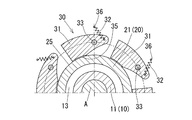
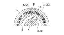
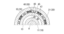
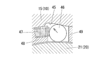
- Sectional view which shows 1st embodiment of the flywheel which concerns on this invention Sectional view along line bb in FIG. 1A
- Sectional view along line cc in FIG. 1A 1 is a longitudinal sectional view showing a transmission mechanism (swing member) of the flywheel shown in FIG. 1A
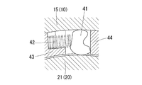
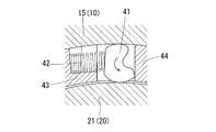
- a longitudinal sectional view showing a third embodiment of a flywheel according to the present invention It is a longitudinal cross-sectional view which shows the effect
- the flywheel includes a main flywheel 10 that rotates about an axis coaxially with a rotation axis A such as a crankshaft of an engine, a sub flywheel 20 that is provided coaxially with the rotation axis A and is relatively rotatable, and a main flywheel. 10 and a plurality of transmission mechanisms 30 provided between the auxiliary flywheel 20.
- the transmission mechanism 30 engages with the main flywheel 10 and the auxiliary flywheel 20 when the rotation speed of the rotation shaft A is smaller than a predetermined rotation speed, and rotates the main flywheel 10 (of the rotation shaft A).
- Rotation is transmitted to the auxiliary flywheel 20, while the rotation between the main flywheel 10 and the auxiliary flywheel 20 is released when the rotational speed of the rotary shaft A is larger than the predetermined rotational speed. It has the function of interrupting transmission of rotation between the flywheel 10 and the auxiliary flywheel 20.
- the predetermined number of revolutions can be determined as appropriate. For example, the number of revolutions can correspond to the idling state of the engine.
- the main flywheel 10 includes a boss portion 11 and a disc portion 12 that extends radially outward from one end of the boss portion 11.
- the rotary shaft A is fitted on the inner diameter surface side of the boss portion 11 by press-fitting or spline fitting, while the bearing 13 is fitted on the outer diameter surface side of the boss portion 11.
- a plurality of insertion holes 14 for inserting a swing shaft 33 of a swing member 31 to be described later are formed in the disc portion 12.
- two ball bearings are used in parallel as the bearing 13, and the inner ring of each bearing 13 is fitted into the boss portion 11 with a clearance fit, while the outer ring of each bearing 13 is the auxiliary flywheel 20.
- the secondary flywheel 20 is provided on the main flywheel 10 via the bearing 13.
- the auxiliary flywheel 20 has a boss portion 21 and a disc portion 22 that extends radially outward from one end of the boss portion 21 (the end opposite to the side on which the disc portion 12 of the main flywheel 10 is formed). And a widened portion 23 provided at the tip of the disc portion 22.
- the outer ring of the bearing 13 provided on the outer diameter side of the main flywheel 10 is press-fitted and fitted to the inner diameter surface side of the boss portion 21.
- the widened portion 23 protrudes in the axial direction so as to approach the main flywheel 10 from the surface of the disc portion 22.
- the outer diameter of the widened portion 23 is substantially the same as the outer diameter of the disc portion 12 of the main flywheel 10 (see FIG. 1A).
- the transmission mechanism 30 includes a plurality of oscillating members 31 provided at equal intervals in the circumferential direction and oscillating urging members 32 that urge each oscillating member 31 as main components.
- the oscillating member 31 is a plate-like member having a bullet shape in side view (see FIG. 1B and the like).
- a rocking shaft 33 is provided in parallel to the rotation axis A near the tip of the rocking member 31 (near the tip of the shell).
- the oscillating shaft 33 is inserted into the insertion hole 14 formed in the main flywheel 10, and the oscillating member 31 is applied to the main flywheel 10 by the centrifugal force generated with the rotation of the rotating shaft A. And can be rotated. By the rotation of the swing shaft 33, the swing member 31 can swing.
- a main fitting portion 34 having periodic peaks and valleys in the circumferential direction is formed on the surface side of the swing member 31 facing the boss portion 21 of the sub flywheel 20 (see FIG. 1C), and FIG. As shown, an elastic member 35 is provided side by side with the main fitting portion 34 in the axial direction. The elastic member 35 is slightly protruded radially inward from the main fitting portion 34 when no external force is applied. The swing member 31 is rotated around the rotation axis A together with the main flywheel 10 by the swing shaft 33.
- a sub fitting portion 24 that can be fitted to the main fitting portion 34 formed on the swing member 31 is formed so as to face the swing member 31.
- a contact surface 25 with which the elastic member 35 provided on the swing member 31 can contact is formed (see FIG. 1B).
- a swing urging member 32 is provided at the tip of the swing member 31 (the bullet-shaped tip).
- the swing biasing member 32 draws the tip end of the swing member 31 toward the fixed end 36 so that the main fitting portion 34 formed on the swing member 31 is changed to the sub flywheel 20.
- the fitting part 24 is securely fitted (see FIG. 1C). As described above, the main fitting portion 34 and the sub fitting portion 24 are fitted to each other, so that no slip occurs between the flywheels 10 and 20, and the inertia mass is widened by increasing the capacity of the sub flywheel 20. Can be made variable.
- the operation of the transmission mechanism 30 will be described with reference to FIGS. 3A to 3C.
- the main fitting portion 34 and the sub-fitting are engaged by the biasing force of the swing biasing member 32.
- the part 24 is in a fitted state (see FIG. 3A).
- the main fitting portion 34 and the sub fitting portion 24 are fitted, the rotation of the rotation axis A (the main flywheel 10) is reliably transmitted to the sub flywheel 20, and the main flywheel 10 and the sub flywheel 20 are transmitted.
- the total sum of the masses contributes to the inertial mass.
- the swing member 31 When the number of rotations of the rotating shaft A further increases and the magnitude of the centrifugal force increases, the swing member 31 further swings, and the contact between the elastic member 35 and the contact surface 25 is also eliminated. Thus, the swinging member 31 and the sub flywheel 20 are separated (see FIG. 3C). Since the swing member 31 and the auxiliary flywheel 20 are separated from each other, only the mass of the main flywheel 10 contributes to the inertial mass.
- the transmission mechanism 30 has a half-clutch state between a state in which the main fitting portion 34 and the sub-fitting portion 24 are fitted and a state in which the swing member 31 and the sub-flywheel 20 are separated from each other.
- this half-clutch state rotation transmission between the main flywheel 10 and the sub flywheel 20 is moderately performed. Therefore, when the flywheels 10 and 20 are switched between the engaged state and the disengaged state. It is possible to prevent the rotation of the engine from becoming unstable due to a sudden change in the transmission of rotation.
- the flywheel includes a main flywheel 10 that rotates about an axis coaxially with a rotation axis A such as a crankshaft of an engine, a sub flywheel 20 that is provided coaxially with the rotation axis A and is relatively rotatable, and a main flywheel.
- 10 is common to the flywheel according to the first embodiment in that it includes a plurality of transmission mechanisms 30 provided between the auxiliary flywheel 20 and the auxiliary flywheel 20.
- the engagement mechanism 40 that engages between the main flywheel 10 and the auxiliary flywheel 20 is different.
- the meshing mechanism 40 includes a sprag 41 provided between the main flywheel 10 and the sub flywheel 20 and a sprag biasing member 42 that biases the sprag 41 in one direction.
- the disc portion 12 of the main flywheel 10 is formed with a flange portion 15 that stands up toward the sub flywheel 20 side.
- support portions 43 and partition walls 44 are alternately formed at a predetermined interval over the entire circumferential direction.
- One sprag 41 is housed in the gap between the support portion 43 and the partition wall 44.
- One end side of the sprag urging member 42 is fixed to the support portion 43, and the other end side of the sprag urging member 42 urges the sprag 41 toward the partition wall 44.
- a seal member 16 is provided at the tip of the flange portion 15, and the seal member 16 prevents foreign matter from entering the inside of the meshing mechanism 40. Note that the sprag 41, the support portion 43, and the partition wall 44 rotate around the rotation axis A together with the main flywheel 10.
- the sprag 41 and the sprag urging member 42 are arranged symmetrically in opposite directions in adjacent gaps. Thus, by arranging symmetrically, even if the main flywheel 10 rotates to any direction of the circumferential direction, the engagement and engagement cutting
- FIG. 6 shows a third embodiment (main part) of a flywheel according to the present invention.
- the mesh mechanism 40 has an inner diameter changing portion 45 formed on the main flywheel 10, the main flywheel 10, and the auxiliary flywheel 20.
- a rotating body urging member 47 that urges the rotating body 46.
- the disc portion 12 of the main flywheel 10 is formed with a flange portion 15 that stands up toward the sub flywheel 20 (see FIG. 4A).
- support portions 48 and partition walls 49 are alternately formed at a predetermined interval over the entire circumferential direction. Roller-like rotating bodies 46 are stored one by one in the gap between the support portion 48 and the partition wall 49.
- the inner diameter changing unit 45 has an inclined surface formed so as to change the radial gap between the main flywheel 10 and the sub flywheel 20, and the rotating body 46 corresponds to the inner diameter changing unit 45. Placed in position. One end side of the rotating body urging member 47 is fixed to the support portion 48, and the other end side of the rotating body urging member 47 is connected to the small diameter side (the main flywheel 10 and the sub flywheel) of the rotating body 46. The wheel 20 is biased toward the partition wall 49 side closest to the radial direction. The rotating body 46, the support portion 48, and the partition wall 49 rotate around the rotation axis A together with the main flywheel 10.
- the rotating body 46 and the rotating body biasing member 47 are symmetrically arranged in the opposite directions in the adjacent gaps. Thus, by arranging symmetrically, even if the main flywheel 10 rotates to any direction of the circumferential direction, the engagement and engagement cutting
- the operation of the transmission mechanism 30 will be described with reference to FIGS. 7A and 7B.
- the rotating body 46 is biased toward the small diameter side of the inner diameter changing portion 45 by the rotating body biasing member 47.
- the rotating body 46 is engaged with the main flywheel 10 and the auxiliary flywheel 20 (see FIG. 7A). In this way, the rotation of the rotating shaft A (main flywheel 10) is reliably transmitted to the auxiliary flywheel 20 by the meshing of the rotating bodies 46, and the total mass of the main flywheel 10 and the auxiliary flywheel 20 is inertial. Contributes to mass.
- the mass of the main flywheel 10 is obtained by changing the meshing state between the main flywheel 10 and the sub flywheel 20 in accordance with the number of rotations of the rotation axis A and separating the sub flywheel 20. Contributes to the inertial mass, and the inertial mass can be adjusted to an optimum state.
- the flywheel shown in each of the above embodiments is merely an example, and as long as it can solve the problem of the present invention that the inertial mass of the flywheel is variable in a wide range with a simple configuration, It is also permitted to change the shape, arrangement, number, etc., or to add parts that do not appear in the above embodiments.
Landscapes
- Engineering & Computer Science (AREA)
- General Engineering & Computer Science (AREA)
- Mechanical Engineering (AREA)
- Physics & Mathematics (AREA)
- Acoustics & Sound (AREA)
- Aviation & Aerospace Engineering (AREA)
- One-Way And Automatic Clutches, And Combinations Of Different Clutches (AREA)
Abstract
回転軸(A)の回転数が予め定めた所定回転数より小さいときに、主フライホイール(10)及び副フライホイール(20)に係合して、主フライホイール(10)の回転を副フライホイール(20)に伝達する一方で、回転軸(A)の回転数が前記所定回転数よりも大きいときに、主フライホイール(10)と副フライホイール(20)との間の係合を解除して主フライホイール(10)と副フライホイール(20)との間の回転の伝達を遮断する伝達機構(30)とを備えたフライホイールである。
Description
この発明は、エンジンのクランクシャフト等の回転軸に設けられるフライホイールに関し、特に回転軸の回転数に対応して、慣性質量の大きさを可変としたものに関する。
エンジンのクランクシャフト等の回転軸には、エンジン等の回転トルクが変動するのに伴って、回転軸の回転数が変動するのを防止するために、フライホイールが設けられることが多い。このフライホイールとして、例えば、下記特許文献1、2に示すものがある。
特許文献1に示すフライホイール(特許文献1の第1図、第2図参照)は、モータ等の回転軸に固定されるボス部と外周リングとをアームで連結し、このアームに移動可能に重錘を外嵌するとともに、アームに装着したコイルスプリングで重錘を回転軸側に付勢する構成を採用している。回転起動時には、各重錘がコイルスプリングの付勢力によって回転軸側に寄せられているので、その慣性質量(イナーシャ)は比較的小さい。このため、モータ等の回転駆動源の負担が小さく、円滑に起動することができる。その一方で、高速回転状態では、重錘に作用する遠心力により各重錘がコイルスプリングの付勢力に抗してアーム上を外周側に移動する。このため、その慣性質量が増大して、回転安定性を向上することができる。
特許文献2に示すフライホイール(特許文献2の第1図等参照)は、クランクシャフト(回転軸)に固定された主フライホイールと、クランクシャフトに回転可能に取り付けられた可変フライホイールと、クランクシャフトの回転を高粘度の粘性流体(シリコンオイル)を介して可変フライホイールに伝達するフライホイールクラッチとを備え、粘性流体の流路を塞ぐボールと、ボールを付勢するスプリングとからなるコントロールバルブによって、フライホイールクラッチによる主フライホイールから可変フライホイールへの回転伝達を制御する構成を採用している。
低速回転状態では、コントロールバルブが開弁して、フライホイールクラッチによって主フライホイールと可変フライホイールがともに回転し、大きな慣性質量が確保される。このため、低速回転域におけるスムーズなエンジン回転に寄与することができる。その一方で、中高速回転状態では、スプリングの付勢力に抗してボールが遠心力で変位し、コントロールバルブか閉弁して、可変フライホイールが主フライホイールから切り離される。可変フライホイールが切り離されることにより、主フライホイールのみがクランクシャフトとともに回転する。主フライホイールのみが回転することにより、両フライホイールがともに回転する場合と比較して慣性質量が小さくなる。このため、中高速回転域におけるアクセルレスポンスの低下や、エンジンブレーキの利きの低下を防止することができる。
特許文献1、2に示すように、低速回転域又は中高速回転域のいずれにおいて慣性質量を大きくして回転の安定を図るのかについては、要求されるエンジン特性に応じて適宜決定される。
特許文献1に記載の構成においては、重錘がアームから着脱不能に外嵌されていて、この重錘の位置によって慣性質量を調節する構成となっており、重錘の移動範囲を拡大したり、重錘の大きさを大きくしたりすることが困難なことが多い。このため、慣性質量の可変範囲をそれほど大きく確保することができないという問題がある。また、特許文献2に記載の構成においては、主フライホイールと可変フライホイールを切り離し可能としたことにより、慣性質量の可変範囲を大きく確保することができる反面、フライホイールクラッチを作動させる粘性流体の流出を防ぐシールが必要になる等、構造が複雑となってコストが嵩む問題がある。
そこで、この発明は、簡便な構成でフライホイールの慣性質量を広い範囲で可変とすることを課題とする。
この課題を解決するために、この発明においては、回転軸と同軸に軸周りに回転する主フライホイールと、前記回転軸と同軸かつ相対回転可能に設けられた副フライホイールと、前記主フライホイールと前記副フライホイールとの間に設けられ、前記回転軸の回転数が予め定めた所定回転数より小さいときに、前記主フライホイール及び前記副フライホイールに係合して、前記主フライホイールの回転を前記副フライホイールに伝達する一方で、前記回転軸の回転数が前記所定回転数よりも大きいときに、前記主フライホイールと前記副フライホイールとの間の係合を解除して前記主フライホイールと前記副フライホイールとの間の回転の伝達を遮断する伝達機構と、を備えたフライホイールを構成した。
このように、主フライホイールと副フライホイールを、両フライホイールに係合自在に設けられた伝達機構で連結し又は切り離すことにより、慣性質量(イナーシャ)の可変範囲を大きく確保することができる。この伝達機構の駆動には、エンジンのクランクシャフト等の回転軸の回転に伴う遠心力が利用される。遠心力を利用することにより、伝達機構を駆動するための複雑な駆動機構を必要とせず、簡便な構成で、回転軸の回転数に対応して慣性質量の調節を行うことができる。
前記構成においては、前記伝達機構が、前記回転軸の回転に伴って生じる遠心力によって前記主フライホイールに対して揺動可能に設けた揺動部材と、前記副フライホイールに臨むように前記揺動部材に形成した主嵌合部と、前記揺動部材に臨むように前記副フライホイールに形成した副嵌合部と、前記揺動部材を前記副フライホイールに向けて付勢して、前記主嵌合部と前記副嵌合部を嵌合可能とする揺動付勢部材と、を備えた構成とすることができる。
このように、主嵌合部と副嵌合部を嵌合させることによって、主フライホイールと副フライホイールの係合状態を確実なものとすることができる。このため、両フライホイールの間で滑りが生じず、副フライホイールの大重量化によって慣性質量を広い範囲で可変とすることができる。
主嵌合部と副嵌合部を嵌合させる構成においては、前記揺動部材又は前記副フライホイールの少なくともいずれか一方に、前記揺動部材と前記副フライホイールとの間に介在可能な弾性部材をさらに備えた構成とすることができる。
このように、弾性部材を設けることにより、主嵌合部と副嵌合部か嵌合することなく弾性部材が副フライホイールに接触した状態(以下、半クラッチ状態と称する。)とすることができる。この半クラッチ状態においては、主フライホイールと副フライホイールとの間の回転の伝達が適度になされるため、両フライホイールの係合状態と係合切断状態の切り替えの際に、回転の伝達が急激に変化してエンジンの回転が不安定になるのを防止することができる。
伝達機構として揺動部材を採用する代わりに、前記伝達機構が、前記回転軸の回転に伴って生じる遠心力の大きさに対応して前記主フライホイールと前記副フライホイールとの間に噛み合う噛合機構である構成とすることもできる。
この構成においては、前記噛合機構が、前記遠心力の大きさに対応して傾きが変化する、前記主フライホイールと前記副フライホイールとの間に設けたスプラグと、前記スプラグを一方向に付勢するスプラグ付勢部材と、を備えた構成とすることができる。
回転軸の回転数が小さく遠心力が小さいときは、スプラグ付勢部材の付勢力によって、スプラグが主フライホイールと副フライホイールとの間に噛み合った状態となって、回転軸(主フライホイール)の回転に伴って副フライホイールも回転する。その一方で、回転軸の回転数が増大して遠心力が大きくなると、スプラグに作用する遠心力によって、スプラグ付勢部材の付勢力に抗してスプラグが傾いて、主フライホイール及び副フライホイールとの間の噛み合いが解除される。このように、回転軸の回転数に対応して、主フライホイールと副フライホイールとの間の噛合状態を変化させて副フライホイールを切り離すことにより、慣性質量を最適な状態に調節することができる。
あるいは、前記噛合機構が、前記主フライホイールと前記副フライホイールとの間の径方向の隙間を変化させる、前記主フライホイールに形成した内径変更部と、前記主フライホイールと前記副フライホイールとの間の前記内径変更部に対応する位置に配置される回転体と、前記回転体を前記内径変更部の小径側に付勢する回転体付勢部材と、を備えた構成とすることもできる。
回転軸の回転数が小さく遠心力が小さいときは、内径変更部の小径側(主フライホイールと副フライホイールが、径方向に最も接近する側)において、回転体付勢部材の付勢力によって、回転体が主フライホイールと副フライホイールとの間に噛み合った状態となって、回転軸(主フライホイール)の回転に伴って副フライホイールも回転する。その一方で、回転軸の回転数が増大して遠心力が大きくなると、回転体に作用する遠心力によって、回転体が回転体付勢部材の付勢力に抗して内径変更部の大径側(主フライホイールと副フライホイールが、径方向に最も離れる側)に移動し、主フライホイールと副フライホイールとの間の噛み合いが解除される。このように、回転軸の回転数に対応して、主フライホイールと副フライホイールとの間の噛合状態を変化させて副フライホイールを切り離すことにより、慣性質量を最適な状態に調節することができる。
噛合機構を採用する構成においては、前記噛合機構が、前記主フライホイール及び前記副フライホイールの周方向逆向きに対称に配置されている構成とすることができる。
このように、周方向逆向きに対称に配置することにより、主フライホイールが周方向のいずれの方向に回転しても、両フライホイールの係合及び係合切断作用が同じように発揮される。
この発明においては、回転軸と同軸に軸周りに回転する主フライホイールと、前記回転軸と同軸かつ相対回転可能に設けられた副フライホイールと、前記主フライホイールと前記副フライホイールとの間に設けられ、前記回転軸の回転数が予め定めた所定回転数より小さいときに、前記主フライホイール及び前記副フライホイールに係合して、前記主フライホイールの回転を前記副フライホイールに伝達する一方で、前記回転軸の回転数が前記所定回転数よりも大きいときに、前記主フライホイールと前記副フライホイールとの間の係合を解除して前記主フライホイールと前記副フライホイールとの間の回転の伝達を遮断する伝達機構と、を備えたフライホイールを構成した。
このように、主フライホイールと副フライホイールを、両フライホイールに係合自在に設けられた伝達機構で連結し又は切り離すことにより、慣性質量(イナーシャ)の可変範囲を大きく確保することができる。この伝達機構の駆動には、エンジンのクランクシャフト等の回転軸の回転に伴う遠心力が利用される。遠心力を利用することにより、伝達機構を駆動するための複雑な駆動機構を必要とせず、簡便な構成で、回転軸の回転数に対応して慣性質量の調節を行うことができる。
この発明に係るフライホイールの第一実施形態を図1A~図1Cに示す。このフライホイールは、エンジンのクランクシャフト等の回転軸Aと同軸に軸周りに回転する主フライホイール10と、回転軸Aと同軸かつ相対回転可能に設けられた副フライホイール20と、主フライホイール10と副フライホイール20の間に設けられる複数の伝達機構30とを備えている。伝達機構30は、回転軸Aの回転数が予め決めた所定回転数よりも小さいときに、主フライホイール10及び副フライホイール20に係合して、主フライホイール10の回転(回転軸Aの回転)を副フライホイール20に伝達する一方で、回転軸Aの回転数が所定回転数よりも大きいときに、主フライホイール10と副フライホイール20との間の係合を解除して、主フライホイール10と副フライホイール20との間の回転の伝達を遮断する機能を有している。この所定回転数は適宜決めることができるが、例えばエンジンのアイドリング状態に対応する回転数とすることができる。
主フライホイール10は、ボス部11と、ボス部11の一端から径方向外向きに拡がる円板部12とから構成される。ボス部11の内径面側には、回転軸Aが圧入又はスプライン嵌合により嵌め込まれる一方で、ボス部11の外径面側には、軸受13が嵌め込まれている。円板部12には、後述する揺動部材31の揺動軸33を挿し込むための挿し込み孔14が複数形成されている。この構成においては、軸受13として二つの玉軸受が並列して用いられており、各軸受13の内輪がボス部11に隙間嵌め嵌合される一方で、各軸受13の外輪が副フライホイール20の後述するボス部21に圧入嵌合されている。
副フライホイール20は、軸受13を介して、主フライホイール10に設けられている。この副フライホイール20は、ボス部21と、ボス部21の一端(主フライホイール10の円板部12を形成した側とは反対側の端部)から径方向外向きに拡がる円板部22と、円板部22の先端に設けられた拡幅部23とから構成される。ボス部21の内径面側には、上述したように、主フライホイール10の外径側に設けられた軸受13の外輪が圧入嵌合されている。この軸受13によって、主フライホイール10と副フライホイール20は、軸周りに相対回転可能となっている。拡幅部23は、円板部22の表面から主フライホイール10に接近するように軸方向に突出している。拡幅部23を形成して、副フライホイール20の質量を増大させることにより、主フライホイール10と副フライホイール20を係合させたときに、十分な大きさの慣性質量を確保することができ、エンジンの低速回転域におけるスムーズなエンジン回転に寄与することができる。拡幅部23の外径は、主フライホイール10の円板部12の外径とほぼ同じとなっている(図1A参照)。
伝達機構30は、円周方向に等間隔に設けられた複数の揺動部材31と、各揺動部材31を付勢する揺動付勢部材32とを主な構成要素としている。揺動部材31は、側面視砲弾形の板状の部材である(図1B等参照)。この揺動部材31の先端寄り(砲弾形の先端寄り)には回転軸Aと平行に揺動軸33が設けられている。揺動軸33は、主フライホイール10に形成された挿し込み孔14に挿し込まれており、揺動部材31は、回転軸Aの回転に伴って生じる遠心力によって、主フライホイール10に対して回転可能となっている。揺動軸33の回転によって、揺動部材31は揺動可能となっている。揺動部材31の副フライホイール20のボス部21に臨む面側には、周方向に周期的な山と谷を有する主嵌合部34が形成されるとともに(図1C参照)、図2に示すように、主嵌合部34と軸方向に並んで弾性部材35が設けられている。弾性部材35は、外力の無負荷時において、主嵌合部34よりも径方向内向きに若干突出した状態となっている。なお、揺動軸33によって、揺動部材31は主フライホイール10と一体となって回転軸A周りに回転する。
副フライホイール20のボス部21の外径面側には、揺動部材31に臨むように、この揺動部材31に形成した主嵌合部34に嵌合可能な副嵌合部24が形成されるとともに(図1C参照)、この揺動部材31に設けた弾性部材35が当接可能な当接面25が形成されている(図1B参照)。
揺動部材31の先端部(砲弾形の先端部)には、揺動付勢部材32が設けられている。この揺動付勢部材32は、揺動部材31の先端部を固定端36側に引き寄せることによって、揺動部材31に形成された主嵌合部34を、副フライホイール20に形成された副嵌合部24に確実に嵌合させる(図1C参照)。このように、主嵌合部34と副嵌合部24が嵌合することにより、両フライホイール10、20の間で滑りが生じず、副フライホイール20の大容量化によって慣性質量を広い範囲で可変とすることができる。
図3A~図3Cを用いて、この伝達機構30の作用について説明する。回転軸A(図1A等参照)の回転数が小さく、揺動部材31に作用する遠心力が比較的小さいときは、揺動付勢部材32の付勢力によって主嵌合部34と副嵌合部24が嵌合した状態となっている(図3A参照)。主嵌合部34と副嵌合部24が嵌合することにより、回転軸A(主フライホイール10)の回転が、確実に副フライホイール20に伝達され、主フライホイール10及び副フライホイール20の質量の総和が慣性質量に寄与する。
回転軸Aの回転数が増加すると、その増加に伴って遠心力の大きさも次第に大きくなる。すると、遠心力が揺動付勢部材32の付勢力に勝って揺動付勢部材32が伸びることで揺動部材31が揺動する。すると、主嵌合部34と副嵌合部24の嵌合が解消して、弾性部材35が当接面25に当接した状態(以下、半クラッチ状態と称する。)となる(図3B参照)。この半クラッチ状態においては、遠心力が相対的に小さく、弾性部材35と当接面25との間の当接力が大きいときは、両者の間の滑り量は小さい。これに対して、遠心力が相対的に大きくなって、弾性部材35と当接面25との当接力が小さくなると、両者の間の滑り量が大きくなる。
そして、さらに回転軸Aの回転数が増加して遠心力の大きさが大きくなると、揺動部材31がさらに揺動して、弾性部材35と当接面25との間の当接も解消して、揺動部材31と副フライホイール20が離間した状態となる(図3C参照)。揺動部材31と副フライホイール20が離間することにより、主フライホイール10の質量のみが慣性質量に寄与する。
この伝達機構30は、主嵌合部34と副嵌合部24が嵌合した状態と、揺動部材31と副フライホイール20が離間した状態との間に、半クラッチ状態が存在する。この半クラッチ状態においては、主フライホイール10と副フライホイール20との間の回転の伝達が適度になされるため、両フライホイール10、20の係合状態と係合切断状態の切り替えの際に、回転の伝達が急激に変化してエンジンの回転が不安定になるのを防止することができる。
この発明に係るフライホイールの第二実施形態を図4A、図4Bに示す。このフライホイールは、エンジンのクランクシャフト等の回転軸Aと同軸に軸周りに回転する主フライホイール10と、回転軸Aと同軸かつ相対回転可能に設けられた副フライホイール20と、主フライホイール10と副フライホイール20の間に設けられる複数の伝達機構30とを備えている点において、第一実施形態に係るフライホイールと共通する一方で、伝達機構30として、回転軸Aの回転に伴って生じる遠心力の大きさに対応して、主フライホイール10と副フライホイール20との間に噛み合う噛合機構40を採用した点において異なっている。
この噛合機構40は、主フライホイール10と副フライホイール20との間に設けられたスプラグ41と、スプラグ41を一方向に付勢するスプラグ付勢部材42とを備えている。主フライホイール10の円板部12には、副フライホイール20側に向けて起立する鍔部15が形成されている。この鍔部15の内径面側には、周方向全体に亘って、支持部43と仕切り壁44が、所定間隔を保って交互に形成されている。支持部43と仕切り壁44との間の隙間には、スプラグ41が一つずつ収納されている。支持部43にはスプラグ付勢部材42の一端側が固定されており、このスプラグ付勢部材42の他端側が、スプラグ41を仕切り壁44側に付勢している。鍔部15の先端にはシール部材16が設けられ、このシール部材16で、噛合機構40の内部に異物が侵入するのを防止している。なお、スプラグ41、支持部43、及び仕切り壁44は、主フライホイール10と一体となって回転軸A周りに回転する。
スプラグ41及びスプラグ付勢部材42は、隣り合う隙間にそれぞれ逆向きに対称に配置されている。このように、対称に配置することにより、主フライホイール10が周方向のいずれの方向に回転しても、両フライホイール10、20の係合及び係合切断作用が同じように発揮される。
図5A、図5Bを用いて、この伝達機構30の作用について説明する。回転軸Aの回転数が小さく、スプラグ41に作用する遠心力が比較的小さいときは、スプラグ付勢部材42によってスプラグ41の所定の傾きが保たれ、このスプラグ41が主フライホイール10(鍔部15)と副フライホイール20(ボス部21)との間に強く噛み合った状態となっている(図5A参照)。このように、スプラグ41が強く噛み合うことによって、回転軸A(主フライホイール10)の回転が、確実に副フライホイール20に伝達され、主フライホイール10及び副フライホイール20の質量の総和が慣性質量に寄与する。
回転軸Aの回転数が増加すると、その増加に伴って遠心力の大きさも次第に大きくなる。すると、この遠心力によって、スプラグ付勢部材42の付勢力に抗して所定の方向にスプラグ41が傾いて(図5B中の矢印参照)、主フライホイール10及び副フライホイール20との間の噛み合いが解除される(あるいは、噛み合いが弱まる)。このように、回転軸Aの回転数に対応して、主フライホイール10と副フライホイール20との間の噛合状態を変化させて副フライホイール20を切り離すことにより、主フライホイール10の質量のみが慣性質量に寄与することとなって、この慣性質量を最適な状態に調節することができる。
この発明に係るフライホイールの第三実施形態(要部)を図6に示す。このフライホイールは、第二実施形態に係るフライホイールの構成と共通する部分が多いが、噛合機構40が、主フライホイール10に形成した内径変更部45と、主フライホイール10と副フライホイール20との間に設けられた回転体(ローラ)46と、回転体46を付勢する回転体付勢部材47とを備えている点において異なっている。主フライホイール10の円板部12には、副フライホイール20側に向けて起立する鍔部15が形成されている(図4A参照)。この鍔部15の内径面側には、周方向全体に亘って、支持部48と仕切り壁49が、所定間隔を保って交互に形成されている。支持部48と仕切り壁49との間の隙間には、ローラ状の回転体46が一つずつ収納されている。内径変更部45は、主フライホイール10と副フライホイール20との間の径方向の隙間を変化させるように形成された傾斜面を有し、回転体46は、この内径変更部45に対応する位置に配置されている。支持部48には回転体付勢部材47の一端側が固定されており、この回転体付勢部材47の他端側が、回転体46を内径変更部45の小径側(主フライホイール10と副フライホイール20が、径方向に最も接近する仕切り壁49側)に付勢している。なお、回転体46、支持部48、及び仕切り壁49は、主フライホイール10と一体となって回転軸A周りに回転する。
回転体46及び回転体付勢部材47は、隣り合う隙間にそれぞれ逆向きに対称に配置されている。このように、対称に配置することにより、主フライホイール10が周方向のいずれの方向に回転しても、両フライホイール10、20の係合及び係合切断作用が同じように発揮される。
図7A、図7Bを用いて、この伝達機構30の作用について説明する。回転軸Aの回転数が小さく、回転体46に作用する遠心力が比較的小さいときは、回転体付勢部材47によって回転体46は内径変更部45の小径側に向けて付勢されており、この回転体46が主フライホイール10と副フライホイール20との間に噛み合った状態となっている(図7A参照)。このように、回転体46が噛み合うことによって、回転軸A(主フライホイール10)の回転が、確実に副フライホイール20に伝達され、主フライホイール10及び副フライホイール20の質量の総和が慣性質量に寄与する。
回転軸Aの回転数が増加すると、その増加に伴って遠心力の大きさも次第に大きくなる。すると、この遠心力によって、回転体付勢部材47の付勢力に抗して回転体46が内径変更部45の傾斜面に沿って、この内径変更部45の大径側(主フライホイールと副フライホイールが、径方向に最も離れる側)に移動し(図7B中の矢印参照)、主フライホイール10及び副フライホイール20との間の噛み合いが解除される(図7B参照)。このように、回転軸Aの回転数に対応して、主フライホイール10と副フライホイール20との間の噛合状態を変化させて副フライホイール20を切り離すことにより、主フライホイール10の質量のみが慣性質量に寄与することとなって、慣性質量を最適な状態に調節することができる。
上記の各実施形態において示したフライホイールはあくまでも一例であって、簡便な構成でフライホイールの慣性質量を広い範囲で可変とする、という本願発明の課題を解決し得る限りにおいて、各構成部品の形状、配置、数等を変更したり、上記の各実施形態には現れていない部品を別途追加したりすることも許容される。
10 主フライホイール
11 ボス部
12 円板部
13 軸受
14 挿し込み孔
15 鍔部
20 副フライホイール
21 ボス部
22 円板部
23 拡幅部
24 副嵌合部
25 当接面
30 伝達機構
31 揺動部材
32 揺動付勢部材
33 揺動軸
34 主嵌合部
35 弾性部材
36 固定端
40 噛合機構
41 スプラグ
42 スプラグ付勢部材
43、48 支持部
44、49 仕切り壁
45 内径変更部
46 回転体
47 回転体付勢部材
A 回転軸
11 ボス部
12 円板部
13 軸受
14 挿し込み孔
15 鍔部
20 副フライホイール
21 ボス部
22 円板部
23 拡幅部
24 副嵌合部
25 当接面
30 伝達機構
31 揺動部材
32 揺動付勢部材
33 揺動軸
34 主嵌合部
35 弾性部材
36 固定端
40 噛合機構
41 スプラグ
42 スプラグ付勢部材
43、48 支持部
44、49 仕切り壁
45 内径変更部
46 回転体
47 回転体付勢部材
A 回転軸
Claims (7)
- 回転軸(A)と同軸に軸周りに回転する主フライホイール(10)と、
前記回転軸(A)と同軸かつ相対回転可能に設けられた副フライホイール(20)と、
前記主フライホイール(10)と前記副フライホイール(20)との間に設けられ、前記回転軸(A)の回転数が予め定めた所定回転数より小さいときに、前記主フライホイール(10)及び前記副フライホイール(20)に係合して、前記主フライホイール(10)の回転を前記副フライホイール(20)に伝達する一方で、前記回転軸(A)の回転数が前記所定回転数よりも大きいときに、前記主フライホイール(10)と前記副フライホイール(20)との間の係合を解除して前記主フライホイール(10)と前記副フライホイール(20)との間の回転の伝達を遮断する伝達機構(30)と、
を備えたフライホイール。 - 前記伝達機構(30)が、
前記回転軸(A)の回転に伴って生じる遠心力によって前記主フライホイール(10)に対して揺動可能に設けた揺動部材(31)と、
前記副フライホイール(20)に臨むように前記揺動部材(31)に形成した主嵌合部(34)と、
前記揺動部材(31)に臨むように前記副フライホイール(20)に形成した副嵌合部(24)と、
前記揺動部材(31)を前記副フライホイール(20)に向けて付勢して、前記主嵌合部(34)と前記副嵌合部(24)を嵌合可能とする揺動付勢部材(32)と、
を備えた請求項1に記載のフライホイール。 - 前記揺動部材(31)又は前記副フライホイール(20)の少なくともいずれか一方に、前記揺動部材(31)と前記副フライホイール(20)との間に介在可能な弾性部材(35)をさらに備えた請求項2に記載のフライホイール。
- 前記伝達機構(30)が、前記回転軸(A)の回転に伴って生じる遠心力の大きさに対応して前記主フライホイール(10)と前記副フライホイール(20)との間に噛み合う噛合機構(40)である請求項1に記載のフライホイール。
- 前記噛合機構(40)が、
前記遠心力の大きさに対応して傾きが変化する、前記主フライホイール(10)と前記副フライホイール(20)との間に設けたスプラグ(41)と、
前記スプラグ(41)を一方向に付勢するスプラグ付勢部材(42)と、
を備えた請求項4に記載のフライホイール。 - 前記噛合機構(40)が、
前記主フライホイール(10)と前記副フライホイール(20)との間の径方向の隙間を変化させる、前記主フライホイール(10)に形成した内径変更部(45)と、
前記主フライホイール(10)と前記副フライホイール(20)との間の前記内径変更部(45)に対応する位置に配置される回転体(46)と、
前記回転体(46)を前記内径変更部(45)の小径側に付勢する回転体付勢部材(47)と、
を備えた請求項4に記載のフライホイール。 - 前記噛合機構(40)が、前記主フライホイール(10)及び前記副フライホイール(20)の周方向逆向きに対称に配置されている請求項4から6のいずれか1項に記載のフライホイール。
Applications Claiming Priority (2)
| Application Number | Priority Date | Filing Date | Title |
|---|---|---|---|
| JP2015-092691 | 2015-04-30 | ||
| JP2015092691A JP2016211597A (ja) | 2015-04-30 | 2015-04-30 | フライホイール |
Publications (1)
| Publication Number | Publication Date |
|---|---|
| WO2016175196A1 true WO2016175196A1 (ja) | 2016-11-03 |
Family
ID=57198481
Family Applications (1)
| Application Number | Title | Priority Date | Filing Date |
|---|---|---|---|
| PCT/JP2016/063022 Ceased WO2016175196A1 (ja) | 2015-04-30 | 2016-04-26 | フライホイール |
Country Status (2)
| Country | Link |
|---|---|
| JP (1) | JP2016211597A (ja) |
| WO (1) | WO2016175196A1 (ja) |
Cited By (2)
| Publication number | Priority date | Publication date | Assignee | Title |
|---|---|---|---|---|
| EP3318703A1 (en) * | 2016-11-07 | 2018-05-09 | Assa Abloy AB | Mechanisms, assemblies and electronic locking system |
| DE102020101505A1 (de) * | 2020-01-23 | 2020-11-19 | Schaeffler Technologies AG & Co. KG | Schwungrad |
Citations (6)
| Publication number | Priority date | Publication date | Assignee | Title |
|---|---|---|---|---|
| JPS59126039U (ja) * | 1983-02-15 | 1984-08-24 | 松下電工株式会社 | 建築用板 |
| JPS60109635A (ja) * | 1983-10-24 | 1985-06-15 | ルーク・ラメレン・ウント・クツプルングスバウ・ゲゼルシヤフト・ミツト・ベシユレンクテル・ハフツング | 回転衝撃を受容若しくは補償するための減衰装置 |
| JPS61103026A (ja) * | 1984-10-24 | 1986-05-21 | Mitsubishi Motors Corp | 可変慣性能率フライホイ−ルユニツト |
| JPH08200402A (ja) * | 1995-01-23 | 1996-08-06 | Aqueous Res:Kk | 発進装置 |
| WO2012073309A1 (ja) * | 2010-11-29 | 2012-06-07 | トヨタ自動車 株式会社 | 内燃機関及び内燃機関の組み付け方法 |
| JP2014177958A (ja) * | 2013-03-13 | 2014-09-25 | Fuji Heavy Ind Ltd | ダンパ装置 |
-
2015
- 2015-04-30 JP JP2015092691A patent/JP2016211597A/ja active Pending
-
2016
- 2016-04-26 WO PCT/JP2016/063022 patent/WO2016175196A1/ja not_active Ceased
Patent Citations (6)
| Publication number | Priority date | Publication date | Assignee | Title |
|---|---|---|---|---|
| JPS59126039U (ja) * | 1983-02-15 | 1984-08-24 | 松下電工株式会社 | 建築用板 |
| JPS60109635A (ja) * | 1983-10-24 | 1985-06-15 | ルーク・ラメレン・ウント・クツプルングスバウ・ゲゼルシヤフト・ミツト・ベシユレンクテル・ハフツング | 回転衝撃を受容若しくは補償するための減衰装置 |
| JPS61103026A (ja) * | 1984-10-24 | 1986-05-21 | Mitsubishi Motors Corp | 可変慣性能率フライホイ−ルユニツト |
| JPH08200402A (ja) * | 1995-01-23 | 1996-08-06 | Aqueous Res:Kk | 発進装置 |
| WO2012073309A1 (ja) * | 2010-11-29 | 2012-06-07 | トヨタ自動車 株式会社 | 内燃機関及び内燃機関の組み付け方法 |
| JP2014177958A (ja) * | 2013-03-13 | 2014-09-25 | Fuji Heavy Ind Ltd | ダンパ装置 |
Cited By (8)
| Publication number | Priority date | Publication date | Assignee | Title |
|---|---|---|---|---|
| EP3318703A1 (en) * | 2016-11-07 | 2018-05-09 | Assa Abloy AB | Mechanisms, assemblies and electronic locking system |
| WO2018083133A3 (en) * | 2016-11-07 | 2018-06-14 | Assa Abloy Ab | Mechanisms, assemblies and electronic locking system |
| CN109952405A (zh) * | 2016-11-07 | 2019-06-28 | 亚萨合莱有限公司 | 机构、组件和电子锁定系统 |
| CN109952405B (zh) * | 2016-11-07 | 2021-06-22 | 亚萨合莱有限公司 | 机构、组件和电子锁定系统 |
| US11514734B2 (en) | 2016-11-07 | 2022-11-29 | Assa Abloy Ab | Mechanisms, assemblies and electronic locking system |
| US11861958B2 (en) | 2016-11-07 | 2024-01-02 | Assa Abloy Ab | Mechanisms, assemblies and electronic locking system |
| US12159496B2 (en) | 2016-11-07 | 2024-12-03 | Assa Abloy Ab | Mechanisms, assemblies and electronic locking system |
| DE102020101505A1 (de) * | 2020-01-23 | 2020-11-19 | Schaeffler Technologies AG & Co. KG | Schwungrad |
Also Published As
| Publication number | Publication date |
|---|---|
| JP2016211597A (ja) | 2016-12-15 |
Similar Documents
| Publication | Publication Date | Title |
|---|---|---|
| CN104105897B (zh) | 隔离断开器 | |
| CN110651133B (zh) | 用于带传动装置的过滤带轮组件 | |
| CN101981351A (zh) | 皮带轮单元 | |
| KR20160127125A (ko) | 절연 디커플러 | |
| JP6906514B2 (ja) | アイソレーティング・デカップラ | |
| JP2015521723A (ja) | 付属装置駆動分断装置 | |
| WO2016175196A1 (ja) | フライホイール | |
| JP5716645B2 (ja) | 捩り振動低減装置 | |
| JP2017109544A (ja) | パワートレイン | |
| JP2006292140A (ja) | スプラグ型ワンウェイクラッチ | |
| JP2019158136A (ja) | 一方向クラッチ | |
| JP6539180B2 (ja) | トルク変動抑制装置、トルクコンバータ、及び動力伝達装置 | |
| US20190257398A1 (en) | Vibration damping device | |
| JP2012163139A (ja) | クラッチ装置 | |
| JP2005188558A (ja) | 逆入力遮断クラッチ | |
| JP2005337398A (ja) | 動力伝達装置 | |
| JP2006234034A (ja) | 逆入力遮断クラッチ | |
| JP2009150474A (ja) | ダンパ装置 | |
| JP4894574B2 (ja) | プーリユニット | |
| JP5256809B2 (ja) | フライホイール構造 | |
| JP2012127451A (ja) | ダイナミックダンパ | |
| JP6683099B2 (ja) | ダンパ付きプーリユニット | |
| JPH04101844U (ja) | 可変慣性フライホイール | |
| CN111801508A (zh) | 单向离合器 | |
| JP2009063040A (ja) | クラッチ内蔵プーリユニット |
Legal Events
| Date | Code | Title | Description |
|---|---|---|---|
| 121 | Ep: the epo has been informed by wipo that ep was designated in this application |
Ref document number: 16786473 Country of ref document: EP Kind code of ref document: A1 |
|
| NENP | Non-entry into the national phase |
Ref country code: DE |
|
| 122 | Ep: pct application non-entry in european phase |
Ref document number: 16786473 Country of ref document: EP Kind code of ref document: A1 |