WO2016175114A1 - 車両用制動装置 - Google Patents
車両用制動装置 Download PDFInfo
- Publication number
- WO2016175114A1 WO2016175114A1 PCT/JP2016/062587 JP2016062587W WO2016175114A1 WO 2016175114 A1 WO2016175114 A1 WO 2016175114A1 JP 2016062587 W JP2016062587 W JP 2016062587W WO 2016175114 A1 WO2016175114 A1 WO 2016175114A1
- Authority
- WO
- WIPO (PCT)
- Prior art keywords
- hydraulic pressure
- master
- bottoming
- pressure
- braking force
- Prior art date
- Legal status (The legal status is an assumption and is not a legal conclusion. Google has not performed a legal analysis and makes no representation as to the accuracy of the status listed.)
- Ceased
Links
Images


Classifications
-
- B—PERFORMING OPERATIONS; TRANSPORTING
- B60—VEHICLES IN GENERAL
- B60T—VEHICLE BRAKE CONTROL SYSTEMS OR PARTS THEREOF; BRAKE CONTROL SYSTEMS OR PARTS THEREOF, IN GENERAL; ARRANGEMENT OF BRAKING ELEMENTS ON VEHICLES IN GENERAL; PORTABLE DEVICES FOR PREVENTING UNWANTED MOVEMENT OF VEHICLES; VEHICLE MODIFICATIONS TO FACILITATE COOLING OF BRAKES
- B60T13/00—Transmitting braking action from initiating means to ultimate brake actuator with power assistance or drive; Brake systems incorporating such transmitting means, e.g. air-pressure brake systems
- B60T13/10—Transmitting braking action from initiating means to ultimate brake actuator with power assistance or drive; Brake systems incorporating such transmitting means, e.g. air-pressure brake systems with fluid assistance, drive, or release
- B60T13/12—Transmitting braking action from initiating means to ultimate brake actuator with power assistance or drive; Brake systems incorporating such transmitting means, e.g. air-pressure brake systems with fluid assistance, drive, or release the fluid being liquid
- B60T13/14—Transmitting braking action from initiating means to ultimate brake actuator with power assistance or drive; Brake systems incorporating such transmitting means, e.g. air-pressure brake systems with fluid assistance, drive, or release the fluid being liquid using accumulators or reservoirs fed by pumps
- B60T13/142—Systems with master cylinder
- B60T13/145—Master cylinder integrated or hydraulically coupled with booster
- B60T13/146—Part of the system directly actuated by booster pressure
-
- B—PERFORMING OPERATIONS; TRANSPORTING
- B60—VEHICLES IN GENERAL
- B60T—VEHICLE BRAKE CONTROL SYSTEMS OR PARTS THEREOF; BRAKE CONTROL SYSTEMS OR PARTS THEREOF, IN GENERAL; ARRANGEMENT OF BRAKING ELEMENTS ON VEHICLES IN GENERAL; PORTABLE DEVICES FOR PREVENTING UNWANTED MOVEMENT OF VEHICLES; VEHICLE MODIFICATIONS TO FACILITATE COOLING OF BRAKES
- B60T7/00—Brake-action initiating means
- B60T7/02—Brake-action initiating means for personal initiation
- B60T7/04—Brake-action initiating means for personal initiation foot actuated
- B60T7/042—Brake-action initiating means for personal initiation foot actuated by electrical means, e.g. using travel or force sensors
-
- B—PERFORMING OPERATIONS; TRANSPORTING
- B60—VEHICLES IN GENERAL
- B60T—VEHICLE BRAKE CONTROL SYSTEMS OR PARTS THEREOF; BRAKE CONTROL SYSTEMS OR PARTS THEREOF, IN GENERAL; ARRANGEMENT OF BRAKING ELEMENTS ON VEHICLES IN GENERAL; PORTABLE DEVICES FOR PREVENTING UNWANTED MOVEMENT OF VEHICLES; VEHICLE MODIFICATIONS TO FACILITATE COOLING OF BRAKES
- B60T8/00—Arrangements for adjusting wheel-braking force to meet varying vehicular or ground-surface conditions, e.g. limiting or varying distribution of braking force
- B60T8/17—Using electrical or electronic regulation means to control braking
- B60T8/172—Determining control parameters used in the regulation, e.g. by calculations involving measured or detected parameters
-
- B—PERFORMING OPERATIONS; TRANSPORTING
- B60—VEHICLES IN GENERAL
- B60T—VEHICLE BRAKE CONTROL SYSTEMS OR PARTS THEREOF; BRAKE CONTROL SYSTEMS OR PARTS THEREOF, IN GENERAL; ARRANGEMENT OF BRAKING ELEMENTS ON VEHICLES IN GENERAL; PORTABLE DEVICES FOR PREVENTING UNWANTED MOVEMENT OF VEHICLES; VEHICLE MODIFICATIONS TO FACILITATE COOLING OF BRAKES
- B60T8/00—Arrangements for adjusting wheel-braking force to meet varying vehicular or ground-surface conditions, e.g. limiting or varying distribution of braking force
- B60T8/17—Using electrical or electronic regulation means to control braking
- B60T8/176—Brake regulation specially adapted to prevent excessive wheel slip during vehicle deceleration, e.g. ABS
- B60T8/1761—Brake regulation specially adapted to prevent excessive wheel slip during vehicle deceleration, e.g. ABS responsive to wheel or brake dynamics, e.g. wheel slip, wheel acceleration or rate of change of brake fluid pressure
-
- B—PERFORMING OPERATIONS; TRANSPORTING
- B60—VEHICLES IN GENERAL
- B60T—VEHICLE BRAKE CONTROL SYSTEMS OR PARTS THEREOF; BRAKE CONTROL SYSTEMS OR PARTS THEREOF, IN GENERAL; ARRANGEMENT OF BRAKING ELEMENTS ON VEHICLES IN GENERAL; PORTABLE DEVICES FOR PREVENTING UNWANTED MOVEMENT OF VEHICLES; VEHICLE MODIFICATIONS TO FACILITATE COOLING OF BRAKES
- B60T8/00—Arrangements for adjusting wheel-braking force to meet varying vehicular or ground-surface conditions, e.g. limiting or varying distribution of braking force
- B60T8/32—Arrangements for adjusting wheel-braking force to meet varying vehicular or ground-surface conditions, e.g. limiting or varying distribution of braking force responsive to a speed condition, e.g. acceleration or deceleration
- B60T8/34—Arrangements for adjusting wheel-braking force to meet varying vehicular or ground-surface conditions, e.g. limiting or varying distribution of braking force responsive to a speed condition, e.g. acceleration or deceleration having a fluid pressure regulator responsive to a speed condition
- B60T8/36—Arrangements for adjusting wheel-braking force to meet varying vehicular or ground-surface conditions, e.g. limiting or varying distribution of braking force responsive to a speed condition, e.g. acceleration or deceleration having a fluid pressure regulator responsive to a speed condition including a pilot valve responding to an electromagnetic force
- B60T8/3615—Electromagnetic valves specially adapted for anti-lock brake and traction control systems
- B60T8/363—Electromagnetic valves specially adapted for anti-lock brake and traction control systems in hydraulic systems
-
- B—PERFORMING OPERATIONS; TRANSPORTING
- B60—VEHICLES IN GENERAL
- B60T—VEHICLE BRAKE CONTROL SYSTEMS OR PARTS THEREOF; BRAKE CONTROL SYSTEMS OR PARTS THEREOF, IN GENERAL; ARRANGEMENT OF BRAKING ELEMENTS ON VEHICLES IN GENERAL; PORTABLE DEVICES FOR PREVENTING UNWANTED MOVEMENT OF VEHICLES; VEHICLE MODIFICATIONS TO FACILITATE COOLING OF BRAKES
- B60T8/00—Arrangements for adjusting wheel-braking force to meet varying vehicular or ground-surface conditions, e.g. limiting or varying distribution of braking force
- B60T8/32—Arrangements for adjusting wheel-braking force to meet varying vehicular or ground-surface conditions, e.g. limiting or varying distribution of braking force responsive to a speed condition, e.g. acceleration or deceleration
- B60T8/34—Arrangements for adjusting wheel-braking force to meet varying vehicular or ground-surface conditions, e.g. limiting or varying distribution of braking force responsive to a speed condition, e.g. acceleration or deceleration having a fluid pressure regulator responsive to a speed condition
- B60T8/40—Arrangements for adjusting wheel-braking force to meet varying vehicular or ground-surface conditions, e.g. limiting or varying distribution of braking force responsive to a speed condition, e.g. acceleration or deceleration having a fluid pressure regulator responsive to a speed condition comprising an additional fluid circuit including fluid pressurising means for modifying the pressure of the braking fluid, e.g. including wheel driven pumps for detecting a speed condition, or pumps which are controlled by means independent of the braking system
- B60T8/4013—Fluid pressurising means for more than one fluid circuit, e.g. separate pump units used for hydraulic booster and anti-lock braking
-
- B—PERFORMING OPERATIONS; TRANSPORTING
- B60—VEHICLES IN GENERAL
- B60T—VEHICLE BRAKE CONTROL SYSTEMS OR PARTS THEREOF; BRAKE CONTROL SYSTEMS OR PARTS THEREOF, IN GENERAL; ARRANGEMENT OF BRAKING ELEMENTS ON VEHICLES IN GENERAL; PORTABLE DEVICES FOR PREVENTING UNWANTED MOVEMENT OF VEHICLES; VEHICLE MODIFICATIONS TO FACILITATE COOLING OF BRAKES
- B60T8/00—Arrangements for adjusting wheel-braking force to meet varying vehicular or ground-surface conditions, e.g. limiting or varying distribution of braking force
- B60T8/32—Arrangements for adjusting wheel-braking force to meet varying vehicular or ground-surface conditions, e.g. limiting or varying distribution of braking force responsive to a speed condition, e.g. acceleration or deceleration
- B60T8/34—Arrangements for adjusting wheel-braking force to meet varying vehicular or ground-surface conditions, e.g. limiting or varying distribution of braking force responsive to a speed condition, e.g. acceleration or deceleration having a fluid pressure regulator responsive to a speed condition
- B60T8/40—Arrangements for adjusting wheel-braking force to meet varying vehicular or ground-surface conditions, e.g. limiting or varying distribution of braking force responsive to a speed condition, e.g. acceleration or deceleration having a fluid pressure regulator responsive to a speed condition comprising an additional fluid circuit including fluid pressurising means for modifying the pressure of the braking fluid, e.g. including wheel driven pumps for detecting a speed condition, or pumps which are controlled by means independent of the braking system
- B60T8/4072—Systems in which a driver input signal is used as a control signal for the additional fluid circuit which is normally used for braking
- B60T8/4081—Systems with stroke simulating devices for driver input
-
- B—PERFORMING OPERATIONS; TRANSPORTING
- B60—VEHICLES IN GENERAL
- B60T—VEHICLE BRAKE CONTROL SYSTEMS OR PARTS THEREOF; BRAKE CONTROL SYSTEMS OR PARTS THEREOF, IN GENERAL; ARRANGEMENT OF BRAKING ELEMENTS ON VEHICLES IN GENERAL; PORTABLE DEVICES FOR PREVENTING UNWANTED MOVEMENT OF VEHICLES; VEHICLE MODIFICATIONS TO FACILITATE COOLING OF BRAKES
- B60T8/00—Arrangements for adjusting wheel-braking force to meet varying vehicular or ground-surface conditions, e.g. limiting or varying distribution of braking force
- B60T8/32—Arrangements for adjusting wheel-braking force to meet varying vehicular or ground-surface conditions, e.g. limiting or varying distribution of braking force responsive to a speed condition, e.g. acceleration or deceleration
- B60T8/34—Arrangements for adjusting wheel-braking force to meet varying vehicular or ground-surface conditions, e.g. limiting or varying distribution of braking force responsive to a speed condition, e.g. acceleration or deceleration having a fluid pressure regulator responsive to a speed condition
- B60T8/44—Arrangements for adjusting wheel-braking force to meet varying vehicular or ground-surface conditions, e.g. limiting or varying distribution of braking force responsive to a speed condition, e.g. acceleration or deceleration having a fluid pressure regulator responsive to a speed condition co-operating with a power-assist booster means associated with a master cylinder for controlling the release and reapplication of brake pressure through an interaction with the power assist device, i.e. open systems
- B60T8/441—Arrangements for adjusting wheel-braking force to meet varying vehicular or ground-surface conditions, e.g. limiting or varying distribution of braking force responsive to a speed condition, e.g. acceleration or deceleration having a fluid pressure regulator responsive to a speed condition co-operating with a power-assist booster means associated with a master cylinder for controlling the release and reapplication of brake pressure through an interaction with the power assist device, i.e. open systems using hydraulic boosters
- B60T8/442—Arrangements for adjusting wheel-braking force to meet varying vehicular or ground-surface conditions, e.g. limiting or varying distribution of braking force responsive to a speed condition, e.g. acceleration or deceleration having a fluid pressure regulator responsive to a speed condition co-operating with a power-assist booster means associated with a master cylinder for controlling the release and reapplication of brake pressure through an interaction with the power assist device, i.e. open systems using hydraulic boosters the booster being a fluid return pump, e.g. in combination with a brake pedal force booster
Definitions
- the present invention relates to a braking device for a vehicle.
- a vehicle braking device which causes a wheel to exert a braking force regardless of a brake operation by utilizing a brake assist control or the like.
- a vehicle braking device is described, for example, in Japanese Patent Laid-Open No. 2009-234407.
- ABS anti-lock brake system
- the basic configuration of the brake system that is, the physique of the master cylinder (and the weight associated therewith) is not discussed at all. That is, the conventional vehicle braking system has room for improvement in terms of the physique of the master cylinder. Accordingly, the inventor has newly focused on the point that the conventional master cylinder is configured to be able to further advance from the normal use area so as to generate an appropriate hydraulic pressure even when a fade occurs.
- the present invention has been made in view of such circumstances, and it is an object of the present invention to provide a vehicle braking device capable of miniaturizing a master cylinder.
- the vehicle braking system has a master cylinder and a master piston that slides in the master cylinder in accordance with a brake operation, and a master chamber whose volume changes according to the movement of the master piston,
- a first hydraulic pressure generation unit generates a hydraulic pressure according to the volume of the master chamber, and a desired hydraulic pressure can be generated in a bottoming state in which the master piston is moved forward by the master cylinder.
- the second hydraulic pressure generation unit generates a hydraulic pressure by the second hydraulic pressure generation unit in the bottoming state, the second hydraulic pressure generation unit, the braking force generation unit applying a braking force corresponding to the input hydraulic pressure to the wheel of the vehicle And a braking force control unit to be input to the braking force generation unit.
- the conventional master cylinder is formed in a size (volume) that can cope with the large braking force so that a large braking force can be generated when a fade occurs.
- the conventional master cylinder is configured to allow the master piston to move forward when a fade occurs. That is, the conventional master cylinder is formed with a volume larger than the volume (normal use area) used at normal times other than at the time of fade so as not to bottom when fade occurs.
- a desired braking force can be generated on the wheels of the vehicle in the bottoming state.
- the volume (stroke length) of the master cylinder which is assumed to be used at the time of fade, becomes unnecessary, and the master cylinder can be miniaturized.
- FIG. 7 is an explanatory view for explaining changes in master pressure and wheel pressure with respect to a brake operation in bottoming control of the first embodiment. It is a flowchart for demonstrating bottoming control of 1st Example. It is explanatory drawing for demonstrating the volume of the conventional master cylinder. It is a block diagram which shows the structure of brake ECU of 2nd Example. It is a flowchart for demonstrating the 2nd bottoming control of 2nd Example. It is a block diagram which shows the structure of the deformation
- the vehicle brake system includes a hydraulic pressure generating unit 1, an operation amount detecting unit 4, an actuator (corresponding to a "second hydraulic pressure generating unit") 5, and a brake.
- An ECU corresponding to a "braking force control unit" 6;
- the hydraulic pressure generation unit 1 includes a brake operation member 11, a booster 12, a cylinder mechanism (corresponding to a "first hydraulic pressure generation unit") 13, a wheel cylinder (W / C) ("the braking force generation unit 14) and 17).
- the brake operation member 11 of the first embodiment includes a brake pedal.
- the booster 12 is a known device and is a device that boosts the stepping force that the driver applies to the brake operation member 11 and transmits it to the cylinder mechanism 13.
- the booster 12 may be, for example, a hydraulic system (a system using a servo pressure) or an electric system. Further, the booster 12 can be said to be a master piston drive unit that drives the master pistons 131 and 132 in accordance with the brake operation.
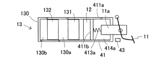
- the cylinder mechanism 13 includes a master cylinder (M / C) 130, master pistons 131 and 132, and a reservoir 133.
- the master pistons 131 and 132 are slidably disposed in the master cylinder 130.
- the master pistons 131 and 132 divide the inside of the master cylinder 130 into a first master chamber 130 a and a second master chamber 130 b.
- the reservoir 133 is a reservoir tank having a conduit communicating with the first master chamber 130a and the second master chamber 130b.
- the reservoir 133 and the master chambers 130 a and 130 b are communicated / blocked by the movement of the master pistons 131 and 132.
- the master cylinder 130 includes a connection port 21 connected to the reservoir 133, seal members 22 and 23, and a connection port 24 connected to the actuator 5.
- the connection port 21 is a port for communicating the reservoir 133 with the second master chamber 130 b.
- the connection port 21 is disposed between the seal members 22 and 23.
- the seal member 22 is disposed on the backward side (right side in FIG. 2) of the connection port 21 and the seal member 23 is disposed on the forward side (left side in FIG. 2) of the connection port 21.
- the seal members 22 and 23 are annular rubber members, and are in fluid-tight contact with the outer peripheral surface of the master piston 132.
- the cross section of the sealing members 22 and 23 cut in the front-rear direction is a convex arc (a U-shape) that is convex toward the connection port 21 side.
- the seal members 22 and 23 of the first embodiment are cup seals.
- the seal members 22 and 23 block the connection port 21 side (close side) and the opposite side (far side) of the connection port 21 with the seal members 22 and 23 as centers. If the pressure (hydraulic pressure and gravity of the reservoir 133) on the connection port 21 side is higher than the pressure (master pressure) on the side opposite to the connection port 21, the seal members 22 and 23 are from the master piston 132 according to their shapes. It deform
- the master piston 132 is formed with a passage 31 communicating the outer peripheral side and the inner peripheral side of the master piston 132.
- the reservoir 133 and the second master chamber 130 b are in communication via the flow path (corresponding to a “second flow path”) 2A.
- the flow path 2A includes the connection port 21, the inner peripheral surface of the master cylinder 130, the outer peripheral surface of the master piston 132, and the passage 31.
- the master piston 132 advances and the passage 31 moves to the advancing side of the seal member 23
- the reservoir 133 and the second master chamber 130 b are shut off by the seal member 23. That is, the flow path 2A of the brake fluid between the reservoir 133 and the second master chamber 130b is configured to be able to be shut off as the master piston 132 moves forward.
- connection port 24 is a port for connecting the second master chamber 130 b and the actuator 5 and is formed on the more advanced side than the seal member 23 of the master cylinder 130.
- the wheel cylinder 14 is disposed at the wheel RL (left rear wheel).
- the wheel cylinder 15 is disposed on a wheel RR (right rear wheel).
- the wheel cylinder 16 is disposed on a wheel FL (left front wheel).
- the wheel cylinder 17 is disposed on a wheel FR (right front wheel).
- Master cylinder 130 and wheel cylinders 14 to 17 are connected via actuator 5.
- the wheel cylinders 14-17 apply braking forces to the wheels RL-FR in accordance with the hydraulic pressure being input.
- a master cylinder pressure (hereinafter referred to as a master pressure) having the same pressure is generated in the first master chamber 130a and the second master chamber 130b.
- the hydraulic pressure generation unit 1 corresponds to the volumes of the first master chamber 130 a and the second master chamber 130 b in the first master chamber 130 a and the second master chamber 130 b whose volumes change according to the movement of the master pistons 131 and 132. Generate a master pressure.
- the master pressure is transmitted to the wheel cylinders 14 to 17 via the actuator 5.
- the operation amount detection unit 4 includes a stroke simulator 41, a pressure sensor (corresponding to a "liquid pressure detection unit") 42, and a conduit 4a.
- the stroke simulator 41 is a device for applying a reaction force to the brake operation member 11 in accordance with the operation of the brake operation member 11.
- the stroke simulator 41 is configured by slidably fitting a simulator piston 412 to a simulator cylinder 411.
- the simulator piston 412 is urged forward by a compression spring 413, and a simulator chamber 414 is formed on the front side of the simulator piston 412. A reaction force corresponding to the fluid pressure of the simulator chamber 414 is applied to the brake operation member 11.
- the pressure sensor 42 is provided in the conduit 4 a connecting the hydraulic pressure generation unit 1 and the simulator chamber 414, and detects the hydraulic pressure of the simulator chamber 414.
- the pressure sensor 42 is communicably connected to the brake ECU 6 and transmits the detection result to the brake ECU 6.
- the operation amount detection unit 4 is configured to be able to detect the brake operation amount even in the bottoming state in which the forward movement of the master pistons 131 and 132 is restricted by the master piston 132. That is, even in the bottoming state, the stroke simulator 41 is configured such that the simulator piston 412 can move forward according to the amount of brake operation on the brake operation member 11.
- the master piston 132 is in contact with the bottom surface (front end surface) of the master cylinder 130, and the master piston 131 is in contact with the rear end surface of the master piston 132.
- the actuator 5 is a device that controls the fluid pressure (hereinafter referred to as wheel pressure) of the wheel cylinders 14 to 17 in accordance with an instruction from the brake ECU 6.
- the actuator 5 includes a hydraulic circuit 5A and a motor 8.
- the hydraulic circuit 5A includes a first piping system 50a and a second piping system 50b.
- the first piping system 50a is a system that controls the hydraulic pressure (wheel pressure) applied to the wheels RL, RR.
- the second piping system 50b is a system that controls the fluid pressure (wheel pressure) applied to the wheels FL, FR. Since the basic configurations of the first piping system 50a and the second piping system 50b are the same, hereinafter, the first piping system 50a will be described, and the description of the second piping system 50b will be omitted.
- the first piping system 50a includes a main pipe (corresponding to a “first flow path”) A, a differential pressure control valve (corresponding to a “solenoid valve”) 51, pressure increasing valves 52 and 53, and a pressure reducing line B
- the pressure reducing valves 54 and 55, the pressure control reservoir 56, the return line C, the pump 57, and the auxiliary line D are provided.
- the main pipe line A is a flow path disposed between the master cylinder 130 and the wheel cylinders 14 and 15 and is a pipe line connecting the master cylinder 130 and the wheel cylinders 14 and 15.
- the differential pressure control valve 51 is a valve which is provided in the main conduit A and controls the main conduit A to a communication state and a differential pressure state.
- the differential pressure control valve 51 controls the differential pressure between the upstream side of the master cylinder 130 and the downstream side of the wheel cylinders 14 and 15 according to the instruction of the brake ECU 6.
- the differential pressure control valve 51 is configured to be able to control the differential pressure between the hydraulic pressure of the portion of the main conduit A on the master cylinder 130 side and the hydraulic pressure of the portion of the main conduit A on the wheel cylinders 14 and 15 side.
- the differential pressure control valve 51 is in the communication state in the non-energized state, and is controlled in the communication state in the normal brake control except for the specific control (automatic brake, anti-slip control, or bottoming control).
- the differential pressure control valve 51 is set such that the differential pressure on both sides becomes larger as the applied control current is larger.
- a check valve 51 a is provided for the differential pressure control valve 51.
- the main pipeline A branches into two pipelines A1 and A2 on the downstream side of the differential pressure control valve 51 so as to correspond to the wheel cylinders 14 and 15.
- the pressure-increasing valves 52 and 53 are electromagnetic valves that open and close in response to an instruction from the brake ECU 6, and are normally open valves that are in an open state (communication state) in a non-energized state.
- the pressure intensifying valve 52 is disposed in the line A1
- the pressure intensifying valve 53 is disposed in the line A2.
- the pressure reducing line B connects between the pressure increasing valve 52 and the wheel cylinder 14 in the line A1 and the pressure regulating reservoir 56, and connects between the pressure increasing valve 53 and the wheel cylinder 15 in the line A2 and the pressure regulating reservoir 56. It is a pipeline that
- the pressure increasing valves 52, 53 are mainly energized at the time of pressure reduction control to be in a closed state, and shut off the master cylinder 130 and the wheel cylinders 14, 15.
- the pressure reducing valves 54 and 55 are electromagnetic valves that open and close according to an instruction from the brake ECU 6, and are normally closed valves that are closed (shut off) when not energized.
- the pressure reducing valve 54 is disposed in the pressure reducing line B on the wheel cylinder 14 side.
- the pressure reducing valve 55 is disposed in the pressure reducing channel B on the wheel cylinder 15 side.
- the pressure reducing valves 54 and 55 are energized and open mainly at the time of pressure reducing control, and communicate the wheel cylinders 14 and 15 with the pressure control reservoir 56 through the pressure reducing pipe line B.
- the pressure control reservoir 56 is a reservoir having a cylinder, a piston, and a biasing member.
- the reflux line C is a line connecting the pressure reducing line B (or the pressure adjusting reservoir 56) and the differential pressure control valve 51 and the pressure increasing valves 52, 53 in the main line A.
- the pump 57 is provided in the reflux line C.
- the pump 57 is a self-priming pump driven by the motor 8.
- the pump 57 causes the brake fluid to flow from the pressure control reservoir 56 to the master cylinder 130 side or the wheel cylinders 14 and 15 side via the reflux line C.
- the motor 8 is energized by a command from the brake ECU 6 via a relay (not shown) and driven.
- the pump 57 and the motor 8 can be said to be one electric pump.
- the auxiliary pipe line D is a pipe line connecting the pressure control reservoir 56 and the upstream side (or the master cylinder 130) of the main pipe line A with respect to the differential pressure control valve 51.
- the brake fluid of the master cylinder 130 is further downstream than the differential pressure control valve 51 in the main conduit A, ie, the wheel cylinders 14, 15, via the auxiliary conduit D and the pressure control reservoir 56 and the like. It is discharged into the side pipeline.
- the pump 57 discharges the brake fluid in the second master chamber 130 b to the portion between the differential pressure control valve 51 of the main conduit A and the wheel cylinders 14 and 15 in response to the drive of the motor 8.
- the actuator 5 of the first embodiment functions as a skid prevention device (ESC) under the control of the brake ECU 6.
- the actuator 5 is configured to be capable of generating a desired fluid pressure in a bottoming state.
- a pressure sensor Y for detecting the fluid pressure (master pressure) of the portion is installed in a portion between the differential pressure control valve 51 of the main conduit A and the master cylinder 130. The pressure sensor Y transmits the detection result to the brake ECU 6.
- the brake ECU 6 is an electronic control unit provided with a CPU, a memory, and the like.
- the brake ECU 6 receives detection results (detection values) from various sensors and controls the operation of the actuator 5.
- the brake ECU 6 executes bottoming control in addition to the ESC control and the ABS control.
- the brake ECU 6 includes a bottoming determination unit 61, a pump control unit 62, an operation amount acquisition unit 63, and a differential pressure setting unit 64 as functions related to bottoming control.
- bottoming control of the brake ECU 6 will be described using the first piping system 50a as an example.
- the bottoming determination unit 61 is a part that determines whether the condition of the cylinder mechanism 13 is in the bottoming state. Specifically, in the bottoming determination unit 61, a master pressure (a detection value of the pressure sensor Y) when bottoming occurs while the pump 57 is not operating is recorded in advance as a determination value. The bottoming determination unit 61 compares the determination value with the received detection value of the pressure sensor Y, and determines the “bottoming state” when the detection value is greater than or equal to the determination value.
- the pump control unit 62 drives the motor 8 to drive the pump 57 when it is determined by the bottoming determination unit 61 to be in the bottoming state.
- the brake fluid in the second master chamber 130b is discharged to a portion between the differential pressure control valve 51 of the main conduit A and the wheel cylinders 14, 15.
- the fluid pressure (master pressure) of the second master chamber 130b becomes atmospheric pressure or negative pressure due to the outflow of the brake fluid.
- the seal member 23 is deformed by the suction of the pump 57, the flow path 2A is opened, and the reservoir 133 and the second master chamber 130b communicate with each other.
- the brake fluid in the reservoir 133 is discharged to the portion between the differential pressure control valve 51 of the main conduit A and the wheel cylinders 14, 15 via the second master chamber 130b. Be done.
- the master pressure is reduced by driving the pump 57 as shown in FIG.
- the operation amount corresponding amount in FIG. 3 relates to the magnitude of the brake operation, and is, for example, a pedal effort or a stroke amount.
- the operation amount acquisition unit 63 acquires the detection value of the pressure sensor 42, and calculates and acquires the operation amount of the brake operation member 11.
- the operation amount acquisition unit 63 calculates an operation amount based on the detection value of the pressure sensor 42.
- the operation amount acquisition unit 63 acquires the operation amount of the brake operation member 11 while the bottoming determination unit 61 determines that the bottoming state is set, and transmits the operation amount to the differential pressure setting unit 64.
- the operation amount acquired by the operation amount acquisition unit 63 is based on the pressure value in the first embodiment, but may be based on, for example, the stroke amount or the pedaling force.
- the differential pressure setting unit 64 sets a differential pressure state of the differential pressure control valve 51 so that a wheel pressure corresponding to the target braking force is generated in order to generate a target braking force corresponding to the received operation amount.
- the actuator 5 generates a desired differential pressure to both sides of the differential pressure control valve 51 in the bottoming state in accordance with an instruction from the brake ECU 6. As a result, as shown in FIG. 3, it is possible to exert the wheel pressure (that is, the braking force) according to the brake operation even after the bottoming state.
- the bottoming determination unit 61 determines whether the cylinder mechanism 13 is in the bottoming state (S101).
- the pump control unit 62 operates the pump 57 (S102).
- the operation amount acquisition unit 63 acquires the operation amount of the brake operation member 11 at the time of bottoming (S103).
- the differential pressure setting unit 64 sets, for the differential pressure control valve 51, a differential pressure according to the operation amount acquired by the operation amount acquisition unit 63 (S104).
- the bottoming control is ended and the brake control is continued.
- the differential pressure may be set to zero if no other control is performed.
- the braking forces corresponding to the brake operation can be generated on the wheels RL to FR. Therefore, the volume (use area at the time of fade) of master cylinder 130 for preventing bottoming at the time of fade becomes unnecessary, and the miniaturization of master cylinder 130 becomes possible.
- the conventional master cylinder is formed with a volume larger than that required for normal use (other than during fading). According to the vehicle brake system of the first embodiment, it is not necessary to provide the use area at the time of fade in FIG. 5, and the volume of the master cylinder 130 can be set to the volume required during normal use (normal use area).
- the master cylinder 130 can be miniaturized.
- the master cylinder is the basic configuration in all braking systems, and its compactness greatly improves the mountability on various vehicle types.
- the brake fluid in the reservoir 133 is drawn into the actuator 5 via the first master chamber 130a and the second master chamber 130b. Ru. That is, the reservoir 133 of the cylinder mechanism 13 and the reservoir of the actuator 5 are shared by the reservoir 133.
- the configuration of the vehicle braking system can be simplified, and the overall size of the vehicle braking system can be reduced.
- the vehicle brake system of the second embodiment has a configuration (hereinafter referred to as "bottoming determination unit 261") corresponding to the bottoming determination unit 61 of the vehicle brake system of the first embodiment, and the vehicle braking system of the first embodiment
- the control corresponding to the bottoming control (hereinafter referred to as “second bottoming control”) is different from the vehicle braking system of the first embodiment.
- the vehicle brake system according to the second embodiment is configured to include a decelerating slip determination unit 263 that determines whether decelerating slip has occurred on the wheels.
- the vehicle braking system of the second embodiment is substantially the same as the vehicle braking system of the first embodiment except for the above three points. Therefore, in the following description, the same reference numerals are given to the configurations substantially the same as the configurations of the vehicle braking system of the first embodiment, and the description thereof will be omitted.
- the bottoming determination unit 261 operates the pump 57 before the bottoming state occurs, and determines whether the bottoming state is set based on the master pressure. For example, the bottoming determination unit 261 operates the pump 57 when the master pressure indicated by the pressure sensor Y is equal to or higher than a predetermined pressure, and sets the differential pressure by the differential pressure control valve 51 to the predetermined pressure. Then, the bottoming determination unit 261 determines that it is in the bottoming state when the master pressure decreases as shown in FIG. 3.
- the predetermined pressure includes 0 Pa.
- the decelerating slip determination unit 263 determines whether decelerating slip has occurred on the wheel based on a known determination method. For example, the deceleration slip determination unit 263 calculates the slip ratio based on the vehicle body speed and the wheel speed, and determines that the deceleration slip is generated on the wheel when the slip ratio is larger than a predetermined threshold.
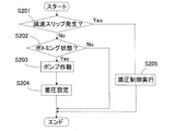
- FIG. 7 shows the flow of second bottoming control.
- the deceleration slip determination unit 263 determines whether or not a deceleration slip is generated on the wheel (S201). When the deceleration slip is not generated on the wheel (S201: No), the bottoming determination unit 261 determines whether or not the bottoming state is set (S202).
- the pump control unit 62 operates the pump (S203), and the differential pressure setting unit 64 sets the differential pressure of the differential pressure control valve 51 to a predetermined pressure (
- the differential pressure setting unit 64 sets the differential pressure of the differential pressure control valve 51 to zero.
- the predetermined pressure in S204 is preferably set based on the fluid pressure at which a reduction slip occurs on the wheel. Therefore, it is conceivable that the predetermined pressure in S204 is variably set based on the vehicle information and the information outside the vehicle.
- the vehicle information includes the steering state, the state of the transmission, the state of the engine, the wheel state, the vehicle body state and the like.
- the out-of-vehicle state includes road surface conditions, weather, navigation information, and the like.
- the differential pressure of the differential pressure control valve 51 set by the differential pressure setting unit 64 may be set to increase in accordance with the elapsed time in the bottoming state in which the deceleration slip is not generated on the wheels. .
- the brake ECU 6 executes the pressure reduction control (S205).
- the braking force can be generated on the wheels RL to FR even in the bottoming state without the pressure sensor 42.
- the operation amount detection unit 4 of the first embodiment may be a pedal force sensor or a stroke sensor.
- a stroke sensor (corresponding to a “movement amount detection unit”) 43 may be disposed.
- the stroke sensor 43 is a sensor that detects the stroke amount of the brake operation member 11 (or its rod).
- the stroke sensor 43 transmits the detection result to the brake ECU 6.
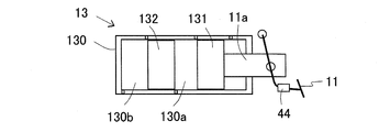
- a stroke simulator 41 may be incorporated into the cylinder mechanism 13.
- a portion corresponding to the simulator cylinder 411 is configured by the rear end portion 411 a of the master cylinder 130 and the wall portion 411 b provided in the master cylinder 130.
- a portion corresponding to the simulator piston 412 is constituted by the rod 11 a assembled to the brake operation member 11.
- the rod 11a is disposed slidably with respect to the opening of the rear end portion 411a, and advances in response to the brake operation.
- a compression spring 413a is disposed between the rod 11a and the wall 411b.
- a simulator chamber 414a is configured by the rear end portion 411a and the wall portion 411b.
- the elastic force of the compression spring 413a acts as a reaction force on the forward movement of the rod 11a.
- the rod 11a can move forward in the bottoming state.
- a configuration that functions as the stroke simulator 41 may be incorporated into the cylinder mechanism 13.
- a stroke sensor 43 may be installed on the vehicle braking device.
- the operation amount detection unit 4 may be configured by the stroke simulator 41 and the stroke sensor 43.
- the operation amount detection unit 4 may be configured by the pedal force sensor 44.
- the pedal force sensor 44 detects the pedal force applied to the brake operation member 11 and transmits it to the brake ECU 6.
- the rod 11 a is connected to the master piston 131.
- the operation amount detection unit 4 may include at least one of the pressure sensor 42, the stroke sensor 43, and the pedal force sensor 44.
- the operation amount acquisition unit 63 may acquire the operation amount based on the pressure value, the stroke amount, and / or the pedal effort.
- 8 to 10 are conceptual diagrams showing the arrangement of the cylinder mechanism 13 in a simplified manner.
- determination of the bottoming state by the bottoming determination unit 61 of the first embodiment may be performed by using the hydraulic pressure of the simulator chamber 414 (the detected value of the pressure sensor 42), the detected value of the stroke sensor 43, and / or the detected value of the pedal force sensor 44. It may be performed using.
- the bottoming determination unit 61 sets the bottoming state as a determination value using a sensor detection value (a detection value of the pressure sensor 42, a detection value of the stroke sensor 43, and / or a detection value of the pedal force sensor 44) at the bottoming simulated in advance. You may judge.
- the present invention is applied to a vehicle braking device having the cylinder mechanism 13 regardless of the presence or absence of the booster 12, the arrangement configuration of the booster 12, and the method of driving the master pistons 131 and 132 by the booster 12. can do.
- the pressure reduction control (S205) of the second embodiment may be part of the ABS control. That is, when the deceleration slip determination unit 263 determines that the deceleration slip is generated on the wheel, the mode of the braking control is shifted to the ABS control.
- the vehicle brake system includes a master cylinder 130 and master pistons 131 and 132 sliding in the master cylinder 130 in accordance with a brake operation, and the volume is adjusted according to the movement of the master pistons 131 and 132.
- the first hydraulic pressure generation unit 13 generates a hydraulic pressure according to the volume of the master chambers 130a and 130b in the master chambers 130a and 130b where the pressure changes, and bottoming in which the master pistons 131 and 132 move forward.
- a second hydraulic pressure generating unit 5 configured to generate a desired hydraulic pressure
- a braking force generating unit 14 applying a braking force corresponding to the input hydraulic pressure to the wheels RL to FL of the vehicle
- a braking force control unit 6 is provided which generates a hydraulic pressure by the second hydraulic pressure generation unit 5 in a bottoming state, and inputs the braking force generation units 14 to 17 to the braking force generation units 14 to 17.
- the vehicle braking system includes a bottoming determination unit 61, 261 that determines that the vehicle is in the bottoming state, and a reduction slip determination unit 263 that determines that a reduction slip is generated on the wheel.
- the second hydraulic pressure generation unit 5 may generate the hydraulic pressure until the reduction slip occurs on the wheel.
- the vehicle braking system includes the operation amount detection unit 4 configured to be capable of detecting the brake operation amount in the bottoming state, and the braking force control unit 6 is detected by the operation amount detection unit 4 in the bottoming state.
- the second hydraulic pressure generation unit 5 may generate a hydraulic pressure corresponding to a certain amount of brake operation.
- the second hydraulic pressure generation unit 5 is provided in a first flow path A of the brake fluid between the first hydraulic pressure generation portion 13 and the braking force generation portions 14 to 17.
- Solenoid valve 51 configured to be able to control the differential pressure between the hydraulic pressure of the portion on the hydraulic pressure generating portion 13 side and the hydraulic pressure of the portion on the braking force generating portion 14 to 17 side of the first flow path A;
- a pump 57 for discharging the brake fluid in 130a and 130b to a portion between the solenoid valve 51 and the braking force generating units 14 to 17 in the first flow path A to generate a desired fluid pressure;
- the pump 57 discharges the brake fluid in the master chambers 130a and 130b to the portion of the first flow path A between the solenoid valve 51 and the braking force generating units 14 to 17, and the solenoid valve 51 generates a differential pressure. It may be generated.
- the first hydraulic pressure generation unit 13 has a reservoir 133 in which the brake fluid is stored, and as the master pistons 131 and 132 move forward, the first fluid pressure generator 13 receives the first brake fluid between the reservoir 133 and the master chambers 130a and 130b.
- the second flow path 2A may be configured to be able to be shut off, and the second flow path 2A may be configured to be openable with the operation of the pump 57 in the bottoming state.
- the vehicle braking device is in a bottoming state when the fluid pressure in the master chambers 130a and 130b is less than or equal to a predetermined fluid pressure in a state in which the pump 57 is operated and a differential pressure is generated.
- the operation amount detection unit 4 includes a simulator cylinder 411 (411a, 411b), a simulator piston 412 (11a) that slides inside the simulator cylinder 411 (411a, 411b) along with a brake operation, and a simulator piston 412 (11a).
- the movement amount detection unit 43 may be configured to detect the movement amount, and the simulator piston 412 (11a) may be configured to be movable in the bottoming state.
- the operation amount detection unit 4 includes a simulator cylinder 411 (411a, 411b), a simulator piston 412 (11a) that slides inside the simulator cylinder 411 (411a, 411b) along with a brake operation, and a simulator piston 412 (11a).
- the hydraulic pressure detection unit 42 for detecting the hydraulic pressure in the simulator chamber 414 (414a) whose volume changes in response to the movement of the simulator piston 412 (11a) in the bottoming state. It is good.
- the first embodiment and the second embodiment may be combined.
- Hydraulic pressure generator 11: brake operation member, 13: cylinder mechanism (first hydraulic pressure generating unit) 130: master cylinder, 131, 132: master piston, 133: reservoir, 130a: first master chamber, 130b: second master chamber, 14, 15, 16, 17: wheel cylinder (braking force generating portion), 2A: flow path (second flow path), 4: Operation amount detection unit, 41: Stroke simulator, 411: Simulator cylinder, 412: Simulator piston, 414, 414a: Simulator room, 42: pressure sensor (liquid pressure detection unit) 43: stroke sensor (movement amount detection unit) 44: treading force sensor, 5: actuator (second hydraulic pressure generating unit), A: Main pipeline (first channel), 51: Differential pressure control valve (solenoid valve), 57: pump 6: 6: brake ECU (braking force control unit) 61, 261: bottoming determination unit 62: pump control unit 63: operation amount acquisition unit, 64: Differential pressure setting unit, 263: Deceleration slip determination unit, RL,
Landscapes
- Engineering & Computer Science (AREA)
- Physics & Mathematics (AREA)
- Transportation (AREA)
- Mechanical Engineering (AREA)
- Fluid Mechanics (AREA)
- Electromagnetism (AREA)
- Regulating Braking Force (AREA)
- Braking Systems And Boosters (AREA)
Priority Applications (3)
| Application Number | Priority Date | Filing Date | Title |
|---|---|---|---|
| DE112016001945.9T DE112016001945T5 (de) | 2015-04-28 | 2016-04-21 | Bremsvorrichtung für ein fahrzeug |
| CN201680024524.1A CN107531219B (zh) | 2015-04-28 | 2016-04-21 | 车用制动装置 |
| US15/568,955 US10449941B2 (en) | 2015-04-28 | 2016-04-21 | Braking device for vehicle |
Applications Claiming Priority (2)
| Application Number | Priority Date | Filing Date | Title |
|---|---|---|---|
| JP2015091765A JP6241448B2 (ja) | 2015-04-28 | 2015-04-28 | 車両用制動装置 |
| JP2015-091765 | 2015-04-28 |
Publications (1)
| Publication Number | Publication Date |
|---|---|
| WO2016175114A1 true WO2016175114A1 (ja) | 2016-11-03 |
Family
ID=57199612
Family Applications (1)
| Application Number | Title | Priority Date | Filing Date |
|---|---|---|---|
| PCT/JP2016/062587 Ceased WO2016175114A1 (ja) | 2015-04-28 | 2016-04-21 | 車両用制動装置 |
Country Status (5)
| Country | Link |
|---|---|
| US (1) | US10449941B2 (enExample) |
| JP (1) | JP6241448B2 (enExample) |
| CN (1) | CN107531219B (enExample) |
| DE (1) | DE112016001945T5 (enExample) |
| WO (1) | WO2016175114A1 (enExample) |
Cited By (1)
| Publication number | Priority date | Publication date | Assignee | Title |
|---|---|---|---|---|
| WO2023008486A1 (ja) * | 2021-07-27 | 2023-02-02 | 株式会社アドヴィックス | 車両の制動制御装置 |
Families Citing this family (3)
| Publication number | Priority date | Publication date | Assignee | Title |
|---|---|---|---|---|
| CN109204279B (zh) * | 2018-11-08 | 2022-08-26 | 清华大学 | 一种驻车制动系统的控制方法及装置 |
| CN109204258A (zh) * | 2018-11-08 | 2019-01-15 | 清华大学 | 一种电子驻车制动系统的控制方法及装置 |
| JP7505229B2 (ja) * | 2020-03-31 | 2024-06-25 | 株式会社アドヴィックス | 車両用制動装置 |
Citations (3)
| Publication number | Priority date | Publication date | Assignee | Title |
|---|---|---|---|---|
| JPH11222115A (ja) * | 1998-02-05 | 1999-08-17 | Toyota Motor Corp | 制動液圧制御装置 |
| JP2001219841A (ja) * | 2000-02-14 | 2001-08-14 | Toyota Motor Corp | ブレーキ装置 |
| JP2004291772A (ja) * | 2003-03-26 | 2004-10-21 | Advics:Kk | 車両用液圧ブレーキ装置 |
Family Cites Families (6)
| Publication number | Priority date | Publication date | Assignee | Title |
|---|---|---|---|---|
| JP3287259B2 (ja) * | 1996-08-02 | 2002-06-04 | トヨタ自動車株式会社 | 制動力制御装置 |
| JP3969169B2 (ja) * | 2002-04-24 | 2007-09-05 | 株式会社アドヴィックス | 車両用電動ブレーキ装置 |
| JP2004291777A (ja) * | 2003-03-26 | 2004-10-21 | Advics:Kk | 車両用液圧ブレーキ装置 |
| JP2004291925A (ja) * | 2003-03-28 | 2004-10-21 | Advics:Kk | 車両用液圧ブレーキ装置 |
| DE102006013626A1 (de) * | 2005-03-23 | 2006-10-05 | Continental Teves Ag & Co. Ohg | Elektrohydraulische Bremsanlage mit Fahrdynamikregelung |
| JP4790744B2 (ja) | 2008-03-27 | 2011-10-12 | 日信工業株式会社 | 車両用ブレーキ液圧制御装置 |
-
2015
- 2015-04-28 JP JP2015091765A patent/JP6241448B2/ja active Active
-
2016
- 2016-04-21 WO PCT/JP2016/062587 patent/WO2016175114A1/ja not_active Ceased
- 2016-04-21 CN CN201680024524.1A patent/CN107531219B/zh active Active
- 2016-04-21 US US15/568,955 patent/US10449941B2/en active Active
- 2016-04-21 DE DE112016001945.9T patent/DE112016001945T5/de active Pending
Patent Citations (3)
| Publication number | Priority date | Publication date | Assignee | Title |
|---|---|---|---|---|
| JPH11222115A (ja) * | 1998-02-05 | 1999-08-17 | Toyota Motor Corp | 制動液圧制御装置 |
| JP2001219841A (ja) * | 2000-02-14 | 2001-08-14 | Toyota Motor Corp | ブレーキ装置 |
| JP2004291772A (ja) * | 2003-03-26 | 2004-10-21 | Advics:Kk | 車両用液圧ブレーキ装置 |
Cited By (1)
| Publication number | Priority date | Publication date | Assignee | Title |
|---|---|---|---|---|
| WO2023008486A1 (ja) * | 2021-07-27 | 2023-02-02 | 株式会社アドヴィックス | 車両の制動制御装置 |
Also Published As
| Publication number | Publication date |
|---|---|
| CN107531219A (zh) | 2018-01-02 |
| JP2016203938A (ja) | 2016-12-08 |
| US20180118181A1 (en) | 2018-05-03 |
| CN107531219B (zh) | 2020-01-10 |
| US10449941B2 (en) | 2019-10-22 |
| JP6241448B2 (ja) | 2017-12-06 |
| DE112016001945T5 (de) | 2018-01-11 |
Similar Documents
| Publication | Publication Date | Title |
|---|---|---|
| US8496301B2 (en) | Vehicle brake mechanism and method for controlling the vehicle brake mechanism | |
| CN105492270B (zh) | 制动控制装置以及制动控制方法 | |
| US9522668B2 (en) | Brake apparatus | |
| US9434367B2 (en) | Brake control apparatus | |
| WO2016035742A1 (ja) | ブレーキ装置 | |
| US10793125B2 (en) | Vehicle braking device | |
| US11964643B2 (en) | Vehicle braking device | |
| WO2016175114A1 (ja) | 車両用制動装置 | |
| WO2018096978A1 (ja) | ブレーキ装置、及びブレーキ装置の制御方法 | |
| US8915555B2 (en) | Brake control device for vehicle | |
| CN111315621A (zh) | 车辆用制动装置 | |
| CN104709253B (zh) | 车辆用制动系统 | |
| CN115335266B (zh) | 车辆用制动装置 | |
| US10800390B2 (en) | Hydraulic pressure generating device and spool position presuming device | |
| JP7218570B2 (ja) | 制動制御装置 | |
| JP3899621B2 (ja) | ペダルストロークシミュレータ付き車両ブレーキ装置 | |
| CN112512876B (zh) | 制动控制装置 | |
| JP5859887B2 (ja) | ブレーキ制御装置 | |
| JP2019059409A (ja) | 車両用制動装置 | |
| WO2014104067A1 (ja) | 車両用液圧ブレーキ装置 | |
| JP6973065B2 (ja) | 車両用制動装置 | |
| JP6724470B2 (ja) | 車両用制動装置 | |
| JP2018144673A (ja) | ブレーキ装置、ブレーキ装置の制御方法およびブレーキシステム | |
| JP2017226383A (ja) | 車両用制動装置 |
Legal Events
| Date | Code | Title | Description |
|---|---|---|---|
| 121 | Ep: the epo has been informed by wipo that ep was designated in this application |
Ref document number: 16786391 Country of ref document: EP Kind code of ref document: A1 |
|
| WWE | Wipo information: entry into national phase |
Ref document number: 15568955 Country of ref document: US |
|
| WWE | Wipo information: entry into national phase |
Ref document number: 112016001945 Country of ref document: DE |
|
| 122 | Ep: pct application non-entry in european phase |
Ref document number: 16786391 Country of ref document: EP Kind code of ref document: A1 |