WO2016174921A1 - 荷電粒子線装置、設置方法 - Google Patents
荷電粒子線装置、設置方法 Download PDFInfo
- Publication number
- WO2016174921A1 WO2016174921A1 PCT/JP2016/056694 JP2016056694W WO2016174921A1 WO 2016174921 A1 WO2016174921 A1 WO 2016174921A1 JP 2016056694 W JP2016056694 W JP 2016056694W WO 2016174921 A1 WO2016174921 A1 WO 2016174921A1
- Authority
- WO
- WIPO (PCT)
- Prior art keywords
- unit
- charged particle
- particle beam
- auxiliary unit
- auxiliary
- Prior art date
- Legal status (The legal status is an assumption and is not a legal conclusion. Google has not performed a legal analysis and makes no representation as to the accuracy of the status listed.)
- Ceased
Links
Images



Classifications
-
- H—ELECTRICITY
- H01—ELECTRIC ELEMENTS
- H01J—ELECTRIC DISCHARGE TUBES OR DISCHARGE LAMPS
- H01J37/00—Discharge tubes with provision for introducing objects or material to be exposed to the discharge, e.g. for the purpose of examination or processing thereof
- H01J37/02—Details
- H01J37/16—Vessels; Containers
-
- H—ELECTRICITY
- H01—ELECTRIC ELEMENTS
- H01J—ELECTRIC DISCHARGE TUBES OR DISCHARGE LAMPS
- H01J37/00—Discharge tubes with provision for introducing objects or material to be exposed to the discharge, e.g. for the purpose of examination or processing thereof
- H01J37/02—Details
- H01J37/248—Components associated with high voltage supply
-
- H—ELECTRICITY
- H01—ELECTRIC ELEMENTS
- H01J—ELECTRIC DISCHARGE TUBES OR DISCHARGE LAMPS
- H01J37/00—Discharge tubes with provision for introducing objects or material to be exposed to the discharge, e.g. for the purpose of examination or processing thereof
- H01J37/26—Electron or ion microscopes; Electron or ion diffraction tubes
- H01J37/28—Electron or ion microscopes; Electron or ion diffraction tubes with scanning beams
-
- H—ELECTRICITY
- H01—ELECTRIC ELEMENTS
- H01J—ELECTRIC DISCHARGE TUBES OR DISCHARGE LAMPS
- H01J2237/00—Discharge tubes exposing object to beam, e.g. for analysis treatment, etching, imaging
- H01J2237/26—Electron or ion microscopes
- H01J2237/28—Scanning microscopes
- H01J2237/2813—Scanning microscopes characterised by the application
-
- H—ELECTRICITY
- H01—ELECTRIC ELEMENTS
- H01J—ELECTRIC DISCHARGE TUBES OR DISCHARGE LAMPS
- H01J37/00—Discharge tubes with provision for introducing objects or material to be exposed to the discharge, e.g. for the purpose of examination or processing thereof
- H01J37/26—Electron or ion microscopes; Electron or ion diffraction tubes
Definitions
- the present invention relates to a charged particle beam apparatus.
- a scanning electron microscope scans a sample with a focused electron beam, thereby detecting electrons generated from the sample, and uses the detected signal to scan the sample on the image display device. Display an image.
- a scanning electron microscope requires a high voltage of several tens of kilovolts due to the nature of an electron gun used to generate an electron beam. Moreover, the inside of an electron microscope must be kept in vacuum for a stable electron beam. Therefore, the conventional scanning electron microscope tends to be large.
- Patent Document 1 discloses the configuration of an electron microscope (FIG. 2).
- an electron microscope main body provided with an electron source, an electron optical system, a sample chamber, a stage, an exhaust system, and the like, and a control device that controls the electron microscope main body and a monitor that displays an observation image are separated. It is held on the gantry.
- Patent Document 1 further discloses a structure of a desktop electron microscope that can be installed on a table or a work table (FIG. 1).
- a desktop electron microscope an electron microscope main body, a control device, and the like including an electron source, an electron optical system, a sample chamber, a stage, an exhaust system, and the like are installed in the same housing.
- a high-performance apparatus can be provided, but it is necessary to ensure a wide installation space because it is large and has a large installation area.
- a transporter such as a lifter is indispensable for the movement, and it is necessary to carry it by a large truck at the time of transport, which is troublesome. For this reason, when it becomes necessary to observe a sample produced without an electron microscope, it must be transported to a laboratory where the electron microscope is located and observed, which is inconvenient from a time point of view.
- the present invention has been made in view of the above-described problems, and an object of the present invention is to provide a charged particle beam apparatus that is compact but has high performance and can be easily transported.
- the present invention relates to a charged particle beam apparatus configured such that a main unit having a functional unit related to a charged particle beam can be attached to and detached from an auxiliary unit having a power supply unit that supplies power to the main unit.
- a small and high performance charged particle beam apparatus can be provided by reducing the weight of the main unit. Moreover, it can be easily transported by separating the main unit and the auxiliary unit.
- FIG. 1 is a side view showing an overall configuration of a charged particle beam apparatus 100 according to Embodiment 1.
- FIG. It is a figure which shows a mode when the rotary pump 8 is accommodated in the auxiliary unit 14.
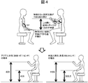
- FIG. 4 is a side view showing a state where a user 40 is sitting on a chair 41 and operates the charged particle beam device 100.
- FIG. It is a figure which shows the height which can change the sample without unreasonableness.
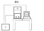
- FIG. 4 is a diagram showing a size example when a user 40 pulls out a sample stage 4 from a main body unit 15. It is a figure which shows the example which isolate
- FIG. 4 is a front view of the main unit 15.
- FIG. It is a side view which shows the whole structure of the charged particle beam apparatus 100 which concerns on Embodiment 3.
- FIG. 4 is a front view of the main unit 15.
- FIG. It is a side view which shows the whole structure of the charged particle beam apparatus 100 which concerns on Embodiment 3.
- FIG. 4 is a front view of the main unit 15.
- FIG. 1 is a side view showing the overall configuration of the charged particle beam apparatus 100 according to the first embodiment.
- the charged particle beam apparatus 100 includes a main unit 15 and an auxiliary unit 14.
- the main unit 15 includes a charged particle beam source 1, an electron optical system mirror body 2 (including a focusing lens, an objective lens, and a detector), a sample chamber 3, a sample stage 4, a turbo molecular pump 5 (main exhaust pump), and turbo molecules.
- An exhaust pipe 6 connecting between the pump 5 and the electron optical system mirror body 2 and the sample chamber 3 and a control board 7 for controlling each part are accommodated.
- the auxiliary unit 14 accommodates the control board 10 that communicates with the power supply unit 9 and the computer 16.
- the lower part of the auxiliary unit 14 is provided with a leg 12 for installing the auxiliary unit 14 and a caster 13 for conveying the auxiliary unit 14.
- a conveying member other than the caster 13 may be used.
- the rotary pump 8 is an auxiliary exhaust pump, is installed outside the main unit 15 and the auxiliary unit 14 and is connected to the turbo molecular pump 5 through an exhaust pipe or the like.
- the main unit 15 can be placed on top of the auxiliary unit 14. At this time, the body unit 15 and the auxiliary unit 14 can be fastened by the fastening member 17. By installing the main unit 15 and the auxiliary unit 14 in an overlapping manner, the entire charged particle beam apparatus 100 can be installed with only the installation area of the auxiliary unit 14 without securing the installation area of the main unit 15.
- the footprint of the main unit 15 and the footprint of the auxiliary unit 14 are substantially the same. Specifically, it is conceivable that the bottom area of the main unit 15 is substantially the same (or below) as the top surface area of the auxiliary unit 14. Thereby, the user can obtain a sense of unity as the entire charged particle beam apparatus 100 even in a state where two units are stacked.
- the whole main body unit 15 and the auxiliary unit 14 can be regarded as one rigid body.
- Some components such as the turbo-molecular pump 5 have a limited operating temperature (for example, 60 ° C. or lower).
- a limited operating temperature for example, 60 ° C. or lower.
- each component is densely packed. Therefore, heat generated from the control substrate 10 and the electron optical system mirror body 2 is trapped inside the apparatus, and the internal temperature of the apparatus tends to increase.
- the component stops or operates abnormally.
- the control board 10 and the power supply unit 9 that generate large heat in the auxiliary unit 14 it is possible to prevent the temperature in the main unit 15 from rising.
- the number of exhaust heat fans installed in the main unit 15 can be reduced, and the exhaust heat fans serving as vibration sources can be moved away from the electron optical system mirror body 2.
- there are plates that partition each unit such as the bottom plate of the main unit 15 and the upper plate of the auxiliary unit 14, it is possible to make it difficult to transmit heat, electromagnetic noise, and the like generated from the auxiliary unit 14 to the main unit 15. .
- a vibration isolating mount 11 is disposed between the bottom surface of the main unit 15 and the sample chamber 3.
- the anti-vibration mount 11 can be configured using a vibration absorbing member such as a damper, for example.
- the vibration isolation mount 11 can suppress external vibrations that propagate to the sample chamber 3 and the electron optical system mirror body 2.
- the leg 12 includes a vibration control mechanism 18.
- the vibration damping mechanism 18 can be configured using a vibration absorbing member such as rubber.
- the vibration suppression mechanism 18 can suppress the vibration generated on the ground from propagating to the auxiliary unit 14 and the main unit 15. As a result, vibration propagating to the sample chamber 3 and the electron optical system mirror body 2 can be reduced.
- a caster 13 is provided below the auxiliary unit 14. By the caster 13, the two units can be transported at the same time in a state where the auxiliary unit 14 and the main unit 15 are overlapped (or further, the fastening unit 17 is fastened).
- FIG. 2 is a diagram showing a state when the rotary pump 8 is housed in the auxiliary unit 14.
- a space for accommodating the rotary pump 8 and other members can be provided in addition to a space for accommodating the power supply unit 9 and the control board 10.
- the space in the auxiliary unit 14 can be used, for example, when the main unit 15 and the auxiliary unit 14 are separated from each other as shown in FIG. .
- the position of the sample stage is 800 to 1000 mm from the ground, and the user 40 needs to raise his arm a little to pull out the sample stage while sitting on the chair 41.
- the position of the sample stage is about 1000 mm from the ground as in the case of the desktop microscope, and it is necessary to pull out the sample stage with the arm raised.
- a load plate is provided under a sample chamber to which a sample stage is attached, and the load plate is larger in the circumferential direction than the sample stage and the sample chamber (see FIG. 2 of Patent Document 1).
- the charged particle beam apparatus 100 is sized so that the user can work without difficulty.
- FIG. 3 is a side view showing a state where the user 40 sits on the chair 41 and operates the charged particle beam device 100.
- the height of the auxiliary unit 14 is approximately the same as the height of the chair 41 (in FIG. 3, the chair 41 is 380 to 410 mm, and the auxiliary unit 14 is 400 mm).
- the height of the main unit 15 is 800 mm.
- the sample stage 4 that the user 40 pulls out from the main unit 15 when exchanging the sample is located at a position of 500 to 750 mm from the ground. This is about the same as the hand height when the user 40 places his hand on the knee. Therefore, the user 40 can easily pull out the sample stage 4 even when sitting on a chair.
- the height that is most important in terms of usability is the height of the sample stage 4 (the sample replacement position) that is actually a part touched by the user, and is 640 mm. This height was determined based on the concept shown in FIG.
- the body size of a large person is assumed to be a 95% male (American male, height of 189.5cm), and the body size of a small person is assumed to be a 5% female (Asian woman, height of 147.1cm). did.
- the shoulder height is 45 degrees forward from the center of the body and the elbow angle is 90 degrees
- the minimum height of the hand It was assumed that the angle was 0 degrees from the center of the body and the elbow angle was 120 degrees.
- the height range of the sample stage 4 that can be changed by a large person without difficulty is 505.5 mm to 1169 mm
- the height range of the sample stage 4 that can be changed by a small person without difficulty is 436 mm. It was found to be ⁇ 800 mm.
- the range where the two ranges overlap is 505 mm to 800 mm, which is the optimum height of the sample stage 4 that allows a large to small person to change the sample without difficulty.
- the height 640 mm of the sample stage 4 of the present embodiment is an almost intermediate position in this ideal range, and there is an advantage that work can be facilitated for many users 40.
- FIG. 5 is a diagram showing a size example when the user 40 pulls out the sample stage 4 from the main unit 15. Since the sample 43 is at a height of 640 mm from the ground, the user 40 can exchange the sample 43 without raising the arm in the same manner as when the sample stage 4 is pulled out. Moreover, since the sample 43 can be looked down from the top when the sample stage 4 is pulled out, the state of the sample 43 can be observed without removing the sample 43 from the sample stage 4 or starting up the user 40 itself. . On the other hand, in a conventional tabletop microscope or large electron microscope, the height of the sample 43 is about 1000 mm from the ground, and when the user 40 is sitting, the sample 43 can be observed only from the side or obliquely. According to the size example shown in FIG. 5, the operability at the time of sample exchange can be improved.
- FIG. 6 is a diagram showing an example in which the main unit 15 and the auxiliary unit 14 are installed separately. By removing the fastening member 17, the main unit 15 and the auxiliary unit 14 can be installed at different positions.
- the main unit 15 and the auxiliary unit 14 are connected by wiring for control and power supply and piping for connecting a back pump.
- the auxiliary unit 14 and the computer 16 are connected by wiring.
- the sample unit 15 In the case of an environment where the user works standing up in a clean room or the like, it is better to use the sample unit 15 with the main unit 15 placed on the desk 23 as shown in FIG. 6 than in a state where two units are stacked as shown in FIG. At this time, the sample stage 4 can be pulled out without the user bending.
- a vibration isolation table may be installed at the lower part of the apparatus. In a conventional large electron microscope, the entire apparatus must be placed on a vibration isolation table, and a large vibration isolation table is required. By separating the main unit 15 and placing it on the vibration isolation table, the size and load resistance of the vibration isolation table can be reduced.
- each unit By separating each unit, it is possible to load each unit even in a vehicle with a low vehicle height during transportation. Therefore, it can be transported without using a large vehicle such as a truck. Thereby, even a small vehicle can be transported, and the charged particle beam device 100 can be transported easily and also to a narrow place.
- the height is suitable for the user 40 to sit and work on the chair 41 with the main unit 15 placed on the auxiliary unit 14.
- the height can also be adjusted separately by the desk 23 by separating the main unit 15 and placing it on the desk 23.
- the charged particle beam apparatus 100 When a part of the charged particle beam apparatus 100 breaks down, it can be quickly restored by replacing one of the main unit 15 or the auxiliary unit 14.
- the conventional charged particle beam apparatus is large and requires a lot of transportation, the charged particle beam apparatus 100 according to the first embodiment can be transported even in a small car, and thus has high mobility and can respond quickly to each unit. It is also possible to replace the unit again after repairing the failed unit. With these characteristics, the operation rate of the charged particle beam apparatus 100 can be increased.
- the performance of the charged particle beam apparatus 100 can be installed in the auxiliary unit 14 different from the main body unit 15 while leaving the feature that it can be installed on a table.
- a power supply unit 9 and a control board 10 that are not affected by the function are arranged.
- the weight reduction of the main body unit 15 can be achieved.
- the charged particle beam device 100 can be enhanced in function, and can be multi-functionalized to cope with high vacuum and low vacuum.
- the charged particle beam apparatus 100 according to the first embodiment can be used even when the main unit 15 and the auxiliary unit 14 are overlapped, or can be used even when these units are separated and the main unit 15 is installed on a table, for example.
- the installation area by the auxiliary unit 14 can be prevented from expanding.
- the main unit 15 can be installed at a location desired by the user, such as on a desk or work table. That is, it can deal with a wide variety of installation environments.
- the charged particle beam device 100 according to the present embodiment can be transported without using a large transport vehicle by separating each unit during transport. Accordingly, it is possible to provide the same transportability as that of the desktop electron microscope while having high performance.
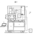
- FIG. 7 is a side view showing the overall configuration of the charged particle beam apparatus 100 according to the present embodiment.
- an anti-vibration mount 35 is provided in place of the anti-vibration mount 11 described in the first embodiment.
- the difference from the first embodiment will be mainly described.
- the anti-vibration mount 35 is attached between the anti-vibration mount mounting member 36 fixed to the side surface of the sample chamber 3 and the anti-vibration mount base 34 fixed to the mount of the main unit 15. Further, an exhaust pipe support member 31 that supports the exhaust pipe 6 was provided, one end of which was connected to the exhaust pipe 6, and the other end was connected to the outer wall of the sample chamber 3. Further, a fork insertion guide 32 is provided on the bottom surface of the main unit 15, and a positioning member 33 is provided on the top surface of the auxiliary unit 14.
- an anti-vibration mount is arranged between a load plate and a gantry arranged under the sample chamber.
- a load plate in Patent Document 1 a material such as iron is used, and its weight is as heavy as several tens of kilograms.
- the load plate is removed and the sample chamber 3 and the electron optical system mirror body 2 are reduced in weight so that the main unit 15 can be placed on the table.
- the vibration effect is weakened.
- the vibration isolating mount 11 is provided in the lower part of the sample chamber 3, the size of the vibration isolating mount 11 is limited, and the vibration isolating effect is suppressed.
- the anti-vibration mount 35 is installed on the side portion of the sample chamber 3. Accordingly, an anti-vibration mount base 34 fixed to the gantry of the main unit 15 and an anti-vibration mount attachment member 36 fixed to the side surface of the sample chamber 3 are provided. Since there is a space to which a detector or the like is attached on the side surface of the sample chamber 3, the width of the main unit 15 does not increase even when the anti-vibration mount 35 is installed on the side of the sample chamber 3. In other words.
- the vibration isolating mount 35 can be made larger than that of the first embodiment without increasing the size of the charged particle beam device 100. Therefore, the vibration isolation effect of the vibration isolation mount can be improved.
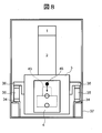
- FIG. 8 is a front view of the main unit 15.
- the upper surface of the anti-vibration mount 35 is disposed so as to substantially coincide with the height of the center of gravity 45 of the charged particle beam device 100 main body. This makes it difficult for vibration modes such as pitching and rolling to occur.
- the sample 43 has substantially the same height as the upper surface and the center of gravity 45 of the vibration-proof mount 35. Therefore, even when the vibration mode occurs, the center of rotation is in the vicinity of the sample 43, and the vibration amplitude in the vicinity of the sample 43 is reduced, so that the influence of vibration can be reduced.
- the turbo molecular pump 5 is not attached to the lower part of the sample chamber 3, but is connected to the electron optical system mirror 2 and the sample chamber 3 and extends to the rear of the apparatus. By attaching to the exhaust pipe 6, the height of the main unit 15 is reduced and the size is reduced.
- the weight of the turbo molecular pump 5 is about 3 kg, when it is attached to the exhaust pipe 6, it has a structure similar to a cantilever beam. For this reason, a vibration system with two degrees of freedom is formed by the vibration isolation mount 35 and the exhaust pipe 6, and there is a possibility that an extra vibration mode is developed and the vibration isolation performance is lowered. Therefore, in the second embodiment, the exhaust pipe support member 31 fixed to the sample chamber 3 and the exhaust pipe 6 are fastened to support the exhaust pipe 6. Thereby, the natural frequency of the vibration system caused by the exhaust pipe 6 and the turbo molecular pump 5 can be increased.
- the difference between the natural frequency and the natural frequency of the vibration isolation mount 35 is increased, and the influence of the vibration mode by the exhaust pipe 6 on the vibration mode of the vibration isolation mount 35 can be reduced.
- the turbo molecular pump 5 rotates at about 1500 Hz during steady operation and becomes a vibration source. Due to the exhaust pipe support member 31, the natural frequency of the higher-order mode of the exhaust pipe 6 is set to a frequency different from the rotational speed of the turbo molecular pump 5, thereby reducing the influence of vibration caused by the rotation of the turbo molecular pump 5.
- the main unit 15 is lighter than a conventional electron microscope, it has a weight of about 80 kg, for example. Therefore, it is assumed that a lifter or the like is used when each unit is attached / detached, when the main unit 15 is installed on a table, and when each unit is transported. Therefore, two rectangular fork insertion guides 32 are fixed to the lower part of the main unit 15. In consideration of the center of gravity of the main unit 15, it is desirable to arrange the main unit 15 so that the center of gravity of the main unit 15 comes to the center of the two fork insertion guides 32.
- the main unit 15 can be lifted in a stable state, and the fork insertion position is the same every time by the fork insertion guide 32, so that it depends on the operator. Stability can be secured when lifted
- the positioning member 33 is a member that assists in positioning when the main unit 15 is placed on the auxiliary unit 14.
- the fork insertion guide 32 is provided with a slit, and the positioning member 33 is fitted into the slit. Thereby, the main unit 15 can be placed at the same position every time.
- the positioning member 33 is arranged so as to position only the front-rear direction (left-right direction toward the drawing) of the charged particle beam apparatus 100, but the left-right direction (depth direction toward the drawing) of the charged particle beam apparatus 100. ) May be provided.
- the charged particle beam apparatus 100 can improve the vibration isolation performance while suppressing the size of the main unit 15 by arranging the vibration isolation mount 35 on the side of the sample chamber 3. it can. Further, by providing a member that supports the exhaust pipe 6, it is possible to suppress the influence of vibration caused by the turbo molecular pump 5.
- the charged particle beam device 100 includes a positioning member 33 and a fork insertion guide 32 in order to assist the work of placing the main unit 15 on the auxiliary unit 14.
- a positioning member 33 and a fork insertion guide 32 in order to assist the work of placing the main unit 15 on the auxiliary unit 14.
- Auxiliary unit 14 The main body unit 15 is placed on and transported by a transport vehicle or a caster 13, and (a1) both units are separated and installed at the installation location, or (a2) on the auxiliary unit 14 at the installation location.
- the main unit 15 is installed as it is, (b) the auxiliary unit 14 and the main unit 15 are separated and conveyed separately by a transport vehicle or caster 13, and (b1) both units are separated at the installation location.
- B2 The main unit 15 is placed on the auxiliary unit 14 at the installation location.
- the configuration example including the main body unit 15 and the auxiliary unit 14 has been described.
- a component such as a detector
- the third embodiment is a configuration example in which the installation area is not changed while maintaining portability even in such a situation.
- the description will focus on differences from the first and second embodiments.
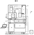
- FIG. 9 is a side view showing the overall configuration of the charged particle beam apparatus 100 according to the third embodiment.
- An optional detector 50 is installed in the sample chamber 3.
- An optional unit 52 that houses a control board 51 for controlling the optional detector 50 is installed between the main unit 15 and the auxiliary unit 14.
- Each unit can be stacked.
- Fastening members 17 fasten the body unit 15 and the option unit 52 and between the auxiliary unit 14 and the option unit 52, respectively.
- the option detector 50, the control board 51, the power supply unit 9 and the like are connected by wiring.
- the footprint of the option unit 52 is substantially the same as that of the main unit 15 and the auxiliary unit 14.
- the optional unit 52 By adding the optional unit 52, components that cannot be installed in the main unit 15 or the auxiliary unit 14 can be added without increasing the installation area of the charged particle beam apparatus 100 as a whole.
- the components accommodated in the option unit 52 can be changed as appropriate according to the components to be added. Specifically, a device or member that implements the function provided by the charged particle beam device 100 and that contains neither the main unit 15 nor the auxiliary unit 14 may be accommodated.
- the number of components accommodated in the option unit 52 is not limited to one, and other control boards and power supplies can be accommodated, for example. Also, a plurality of option units 52 can be added. Since each unit is configured to be able to be stacked, even if the function of the charged particle beam device 100 is added by the option unit 52, the installation area does not change, and the usability and design of the device are maintained. Further, all units can be transported at once by the caster 13.
- the option unit 52 can also be used to adjust the height of the main unit 15. Since the physique and feeling of use differ depending on the user, the height of the main unit 15 from the ground can be varied by using the option unit 52 as a spacer for height adjustment. Thereby, high operability can be provided to a wide range of users. Further, the vibration isolation effect can be improved by using the optional unit 52 as a vibration isolation table.
- the present invention is not limited to the embodiments described above, and includes various modifications.
- the above embodiment has been described in detail for easy understanding of the present invention, and is not necessarily limited to the one having all the configurations described.
- a part of the configuration of one embodiment can be replaced with the configuration of another embodiment.
- the configuration of another embodiment can be added to the configuration of a certain embodiment. Further, with respect to a part of the configuration of each embodiment, another configuration can be added, deleted, or replaced.
Landscapes
- Chemical & Material Sciences (AREA)
- Analytical Chemistry (AREA)
- Analysing Materials By The Use Of Radiation (AREA)
Abstract
Description
図1は、本実施形態1に係る荷電粒子線装置100の全体構成を示す側面図である。荷電粒子線装置100は、本体ユニット15と補助ユニット14を備える。本体ユニット15は、荷電粒子線源1、電子光学系鏡体2(集束レンズ、対物レンズ、検出器を含む)、試料室3、試料ステージ4、ターボ分子ポンプ5(主排気ポンプ)、ターボ分子ポンプ5と電子光学系鏡体2や試料室3との間をつなぐ排気管6、各部を制御する制御基板7を収容する。補助ユニット14は、電源ユニット9、コンピュータ16と通信する制御基板10を収容する。
図7は、本実施形態に係る荷電粒子線装置100の全体構成を示す側面図である。本実施形態においては、実施形態1で説明した防振マウント11に代えて防振マウント35を設けている。以下、実施形態1との相違点を中心に説明する。
実施形態1~2では、本体ユニット15と補助ユニット14を備える構成例について説明した。ユーザの要望によっては、検出器などの構成要素を追加的に装着する必要が生じる場合があり、その検出器を動作させるための制御基板も追加する必要がある。本実施形態3では、そのような状況においても可搬性を維持しつつ設置面積も変えない構成例である。以下、実施形態1~2との相違点を中心に説明する。
本発明は上記した実施形態の形態に限定されるものではなく、様々な変形例が含まれる。上記実施形態は本発明を分かりやすく説明するために詳細に説明したものであり、必ずしも説明した全ての構成を備えるものに限定されるものではない。また、ある実施形態の構成の一部を他の実施形態の構成に置き換えることもできる。また、ある実施形態の構成に他の実施形態の構成を加えることもできる。また、各実施形態の構成の一部について、他の構成を追加・削除・置換することもできる。
Claims (19)
- 本体ユニットと補助ユニットを有する荷電粒子線装置であって、
前記本体ユニットは、
荷電粒子を生成する荷電粒子源、
前記荷電粒子を試料に対して照射する光学系、
前記試料を載置する試料ステージ、
前記試料ステージを収容する試料室、
を収容し、
前記補助ユニットは、
前記本体ユニットに対して電力を供給する電源部を収容し、
前記補助ユニットの上に前記本体ユニットを着脱できるように構成されている
ことを特徴とする荷電粒子線装置。 - 前記本体ユニットの底面面積は、前記補助ユニットの上面面積以下に構成されている
ことを特徴とする請求項1記載の荷電粒子線装置。 - 前記補助ユニットの上に前記本体ユニットを載置したときに、前記試料ステージの試料設置位置が地面から505~800mmの位置にある
ことを特徴とする請求項1記載の荷電粒子線装置。 - 前記補助ユニットは、前記補助ユニットを床面に載置した状態で運搬するための運搬部品を備える
ことを特徴とする請求項1記載の荷電粒子線装置。 - 前記補助ユニットと設置面との間に前記補助ユニットに対して加えられる振動を抑制する制振機構を備える
ことを特徴とする請求項1記載の荷電粒子線装置。 - 前記荷電粒子線装置は、前記本体ユニットを前記補助ユニットの上に載置したとき前記本体ユニットと前記補助ユニットを締結する締結部材を備える
ことを特徴とする請求項1記載の荷電粒子線装置。 - 前記荷電粒子線装置は、前記光学系と前記試料室を排気する排気装置を備え、
前記補助ユニットは、前記排気装置を収容する空間を有する
ことを特徴とする請求項1記載の荷電粒子線装置。 - 前記本体ユニットは、前記本体ユニットの振動が前記試料室に対して伝搬することを抑制する防振部材を備える
ことを特徴とする請求項1記載の荷電粒子線装置。 - 前記防振部材は、前記試料室の側面に配置されている
ことを特徴とする請求項8記載の荷電粒子線装置。 - 前記本体ユニットは、搬送機器が前記本体ユニットを搬送するとき使用するリフトアームをガイドするガイド機構を備える
ことを特徴とする請求項1記載の荷電粒子線装置。 - 前記補助ユニットは、前記本体ユニットを前記補助ユニットの上に載置するとき前記本体ユニットを位置決めする位置決め部材を備える
ことを特徴とする請求項1記載の荷電粒子線装置。 - 前記荷電粒子線装置は、前記光学系と前記試料室を排気する排気装置を備えるとともに、前記排気装置と前記光学系および前記排気装置と前記試料室を接続する排気管を備え、
前記本体ユニットは、前記排気装置と前記排気管を収容し、
前記荷電粒子線装置はさらに、一端が前記試料室に接続され、他端が前記排気管に接続された排気管支持部材を備える
ことを特徴とする請求項1記載の荷電粒子線装置。 - 前記荷電粒子線装置はさらに、
前記本体ユニットと前記補助ユニットとの間に配置されるオプションユニット、
前記本体ユニットと前記オプションユニットを締結する部材、
前記補助ユニットと前記オプションユニットを締結する部材、
を備えることを特徴とする請求項1記載の荷電粒子線装置。 - 前記オプションユニットは、前記荷電粒子線装置が提供する機能を実装した装置のうち前記本体ユニットと前記補助ユニットのいずれも収容していないものを収容する
ことを特徴とする請求項13記載の荷電粒子線装置。 - 補助ユニットの上に本体ユニットを着脱できるように構成されている荷電粒子線装置の設置方法であって、
荷電粒子を生成する荷電粒子源、前記荷電粒子を試料に対して照射する光学系、前記試料を載置する試料ステージ、および前記試料ステージを収容する試料室、を収容する前記本体ユニットと、前記本体ユニットに対して電力を供給する電源部を収容する前記補助ユニットを分離して個別に、または前記補助ユニットの上に前記本体ユニットを載置して、設置場所に対して搬送する搬送ステップ、
前記本体ユニットと前記補助ユニットを前記設置場所においてそれぞれ設置する設置ステップ、
を有することを特徴とする設置方法。 - 前記搬送ステップにおいては、前記本体ユニットと前記補助ユニットを分離して個別に搬送し、
前記設置ステップにおいては、前記本体ユニットと前記補助ユニットを分離したままそれぞれ設置する
ことを特徴とする請求項15記載の設置方法。 - 前記搬送ステップにおいては、前記本体ユニットと前記補助ユニットを分離して個別に搬送し、
前記設置ステップにおいては、前記補助ユニットを前記設置場所において設置した後、前記本体ユニットを前記補助ユニットの上に載置する
ことを特徴とする請求項15記載の設置方法。 - 前記搬送ステップにおいては、前記本体ユニットを前記補助ユニットの上に載置した状態で前記荷電粒子線装置を搬送し、
前記設置ステップにおいては、前記本体ユニットと前記補助ユニットを分離して個別に設置する
ことを特徴とする請求項15記載の設置方法。 - 前記搬送ステップにおいては、前記本体ユニットを前記補助ユニットの上に載置した状態で前記荷電粒子線装置を搬送し、
前記設置ステップにおいては、前記本体ユニットを前記補助ユニットの上に載置した状態で前記設置場所において前記荷電粒子線装置をそのまま設置する
ことを特徴とする請求項15記載の設置方法。
Priority Applications (4)
| Application Number | Priority Date | Filing Date | Title |
|---|---|---|---|
| US15/318,455 US10008361B2 (en) | 2015-04-28 | 2016-03-04 | Charged particle beam device and installation method |
| CN201680001828.6A CN106537552B (zh) | 2015-04-28 | 2016-03-04 | 带电粒子射线装置、设置方法 |
| JP2016564285A JP6246393B2 (ja) | 2015-04-28 | 2016-03-04 | 荷電粒子線装置、設置方法 |
| DE112016000047.2T DE112016000047B4 (de) | 2015-04-28 | 2016-03-04 | Mit einem Strahl geladener Teilchen arbeitende Vorrichtung und Installationsverfahren |
Applications Claiming Priority (2)
| Application Number | Priority Date | Filing Date | Title |
|---|---|---|---|
| JP2015091732 | 2015-04-28 | ||
| JP2015-091732 | 2015-04-28 |
Publications (1)
| Publication Number | Publication Date |
|---|---|
| WO2016174921A1 true WO2016174921A1 (ja) | 2016-11-03 |
Family
ID=57199186
Family Applications (1)
| Application Number | Title | Priority Date | Filing Date |
|---|---|---|---|
| PCT/JP2016/056694 Ceased WO2016174921A1 (ja) | 2015-04-28 | 2016-03-04 | 荷電粒子線装置、設置方法 |
Country Status (5)
| Country | Link |
|---|---|
| US (1) | US10008361B2 (ja) |
| JP (1) | JP6246393B2 (ja) |
| CN (1) | CN106537552B (ja) |
| DE (1) | DE112016000047B4 (ja) |
| WO (1) | WO2016174921A1 (ja) |
Citations (4)
| Publication number | Priority date | Publication date | Assignee | Title |
|---|---|---|---|---|
| JPS5596558U (ja) * | 1978-12-27 | 1980-07-04 | ||
| JPS6179450U (ja) * | 1984-10-31 | 1986-05-27 | ||
| JPH0982258A (ja) * | 1995-09-14 | 1997-03-28 | Hitachi Ltd | 電子顕微鏡 |
| JP2007003397A (ja) * | 2005-06-24 | 2007-01-11 | Fuji Electric Holdings Co Ltd | 試料分析装置 |
Family Cites Families (12)
| Publication number | Priority date | Publication date | Assignee | Title |
|---|---|---|---|---|
| US3873831A (en) * | 1971-02-05 | 1975-03-25 | Max Planck Gesellschaft | Particle-beam device equipped with a foundation supported to permit swinging movement |
| US5160847A (en) * | 1989-05-03 | 1992-11-03 | The Parvus Corporation | Dynamic multivane electron arc beam collimator |
| DE69621540T2 (de) * | 1995-09-14 | 2003-01-09 | Hitachi, Ltd. | Elektronenmikroskop |
| JP3667884B2 (ja) * | 1996-06-27 | 2005-07-06 | Jfeスチール株式会社 | 局所分析装置 |
| JP2002184337A (ja) * | 2000-12-11 | 2002-06-28 | Jeol Ltd | 走査電子顕微鏡 |
| JP2008226683A (ja) * | 2007-03-14 | 2008-09-25 | Hitachi High-Technologies Corp | 荷電粒子線装置 |
| US8809782B2 (en) | 2009-07-30 | 2014-08-19 | Hitachi High-Technologies Corporation | Scanning electron microscope |
| JP5044005B2 (ja) * | 2010-11-08 | 2012-10-10 | マイクロXジャパン株式会社 | 電界放射装置 |
| JP5699023B2 (ja) * | 2011-04-11 | 2015-04-08 | 株式会社日立ハイテクノロジーズ | 荷電粒子線装置 |
| JP5825964B2 (ja) * | 2011-10-05 | 2015-12-02 | 株式会社日立ハイテクノロジーズ | 検査又は観察装置及び試料の検査又は観察方法 |
| JP2016027525A (ja) * | 2012-10-16 | 2016-02-18 | 株式会社日立ハイテクノロジーズ | 荷電粒子線源の冷却機構を具備する荷電粒子線装置及び荷電粒子線源 |
| US9994956B2 (en) * | 2014-08-11 | 2018-06-12 | University Of Kansas | Apparatus for in situ deposition of multilayer structures via atomic layer deposition and ultra-high vacuum physical or chemical vapor deposition |
-
2016
- 2016-03-04 DE DE112016000047.2T patent/DE112016000047B4/de not_active Expired - Fee Related
- 2016-03-04 WO PCT/JP2016/056694 patent/WO2016174921A1/ja not_active Ceased
- 2016-03-04 CN CN201680001828.6A patent/CN106537552B/zh active Active
- 2016-03-04 US US15/318,455 patent/US10008361B2/en active Active
- 2016-03-04 JP JP2016564285A patent/JP6246393B2/ja active Active
Patent Citations (4)
| Publication number | Priority date | Publication date | Assignee | Title |
|---|---|---|---|---|
| JPS5596558U (ja) * | 1978-12-27 | 1980-07-04 | ||
| JPS6179450U (ja) * | 1984-10-31 | 1986-05-27 | ||
| JPH0982258A (ja) * | 1995-09-14 | 1997-03-28 | Hitachi Ltd | 電子顕微鏡 |
| JP2007003397A (ja) * | 2005-06-24 | 2007-01-11 | Fuji Electric Holdings Co Ltd | 試料分析装置 |
Also Published As
| Publication number | Publication date |
|---|---|
| JP6246393B2 (ja) | 2017-12-13 |
| CN106537552B (zh) | 2018-11-06 |
| DE112016000047B4 (de) | 2021-01-28 |
| CN106537552A (zh) | 2017-03-22 |
| US20170169988A1 (en) | 2017-06-15 |
| DE112016000047T5 (de) | 2017-03-23 |
| JPWO2016174921A1 (ja) | 2017-05-18 |
| US10008361B2 (en) | 2018-06-26 |
Similar Documents
| Publication | Publication Date | Title |
|---|---|---|
| US7931243B2 (en) | Speaker with monitor mountable stand | |
| JP5867992B2 (ja) | 改良型能動振動絶縁システム | |
| CN102551770B (zh) | 具有驱动轮悬挂的便携式x射线机 | |
| CN105276073B (zh) | 一种用于光学载荷的多维多级减振装置 | |
| JP2008018938A (ja) | 幼児用座席を自動車に実装させるための基盤 | |
| CN1849467A (zh) | 除振方法及其装置 | |
| US20130213169A1 (en) | Mass damper for semiconductor wafer handling end effector | |
| JP6246393B2 (ja) | 荷電粒子線装置、設置方法 | |
| JPH09184537A (ja) | 除振装置 | |
| US9394966B2 (en) | Vibration suppression apparatus and vibration suppression method | |
| JP2015208573A (ja) | 放射線発生用装置 | |
| CN111594714A (zh) | 一种可移动电源设备减振系统 | |
| JP2001093456A (ja) | 荷電粒子ビーム装置 | |
| CN102473577B (zh) | 扫描电子显微镜 | |
| JP6695752B2 (ja) | 什器 | |
| KR101604269B1 (ko) | 수동자동조심형 수동수평레벨조절기구를 갖는 미세진동제어장치 | |
| JP5993716B2 (ja) | デスク | |
| JP2013036511A (ja) | 除振システム | |
| JP7336594B2 (ja) | 荷電粒子線装置 | |
| CN110850575A (zh) | 手术显微镜装置 | |
| JPH10169701A (ja) | 能動的除振装置 | |
| JPWO2015053209A1 (ja) | 荷電粒子装置 | |
| KR102836573B1 (ko) | 방진 브라켓을 포함하는 프레임 구조물 | |
| JP2008142260A (ja) | 被検体支持装置およびx線撮影装置 | |
| JP2017207928A (ja) | 制振装置 |
Legal Events
| Date | Code | Title | Description |
|---|---|---|---|
| ENP | Entry into the national phase |
Ref document number: 2016564285 Country of ref document: JP Kind code of ref document: A |
|
| WWE | Wipo information: entry into national phase |
Ref document number: 112016000047 Country of ref document: DE |
|
| WWE | Wipo information: entry into national phase |
Ref document number: 15318455 Country of ref document: US |
|
| 121 | Ep: the epo has been informed by wipo that ep was designated in this application |
Ref document number: 16786198 Country of ref document: EP Kind code of ref document: A1 |
|
| 122 | Ep: pct application non-entry in european phase |
Ref document number: 16786198 Country of ref document: EP Kind code of ref document: A1 |