WO2016167173A1 - 画像認識システム、画像認識方法、ホログラム記録媒体、ホログラム再生装置および画像撮影装置 - Google Patents
画像認識システム、画像認識方法、ホログラム記録媒体、ホログラム再生装置および画像撮影装置 Download PDFInfo
- Publication number
- WO2016167173A1 WO2016167173A1 PCT/JP2016/061377 JP2016061377W WO2016167173A1 WO 2016167173 A1 WO2016167173 A1 WO 2016167173A1 JP 2016061377 W JP2016061377 W JP 2016061377W WO 2016167173 A1 WO2016167173 A1 WO 2016167173A1
- Authority
- WO
- WIPO (PCT)
- Prior art keywords
- image
- hologram
- medium
- information
- recognition method
- Prior art date
- Legal status (The legal status is an assumption and is not a legal conclusion. Google has not performed a legal analysis and makes no representation as to the accuracy of the status listed.)
- Ceased
Links
Images









Classifications
-
- B—PERFORMING OPERATIONS; TRANSPORTING
- B42—BOOKBINDING; ALBUMS; FILES; SPECIAL PRINTED MATTER
- B42D—BOOKS; BOOK COVERS; LOOSE LEAVES; PRINTED MATTER CHARACTERISED BY IDENTIFICATION OR SECURITY FEATURES; PRINTED MATTER OF SPECIAL FORMAT OR STYLE NOT OTHERWISE PROVIDED FOR; DEVICES FOR USE THEREWITH AND NOT OTHERWISE PROVIDED FOR; MOVABLE-STRIP WRITING OR READING APPARATUS
- B42D25/00—Information-bearing cards or sheet-like structures characterised by identification or security features; Manufacture thereof
- B42D25/30—Identification or security features, e.g. for preventing forgery
- B42D25/328—Diffraction gratings; Holograms
-
- G—PHYSICS
- G03—PHOTOGRAPHY; CINEMATOGRAPHY; ANALOGOUS TECHNIQUES USING WAVES OTHER THAN OPTICAL WAVES; ELECTROGRAPHY; HOLOGRAPHY
- G03H—HOLOGRAPHIC PROCESSES OR APPARATUS
- G03H1/00—Holographic processes or apparatus using light, infrared or ultraviolet waves for obtaining holograms or for obtaining an image from them; Details peculiar thereto
- G03H1/0005—Adaptation of holography to specific applications
-
- G—PHYSICS
- G03—PHOTOGRAPHY; CINEMATOGRAPHY; ANALOGOUS TECHNIQUES USING WAVES OTHER THAN OPTICAL WAVES; ELECTROGRAPHY; HOLOGRAPHY
- G03H—HOLOGRAPHIC PROCESSES OR APPARATUS
- G03H1/00—Holographic processes or apparatus using light, infrared or ultraviolet waves for obtaining holograms or for obtaining an image from them; Details peculiar thereto
- G03H1/0005—Adaptation of holography to specific applications
- G03H1/0011—Adaptation of holography to specific applications for security or authentication
-
- G—PHYSICS
- G03—PHOTOGRAPHY; CINEMATOGRAPHY; ANALOGOUS TECHNIQUES USING WAVES OTHER THAN OPTICAL WAVES; ELECTROGRAPHY; HOLOGRAPHY
- G03H—HOLOGRAPHIC PROCESSES OR APPARATUS
- G03H1/00—Holographic processes or apparatus using light, infrared or ultraviolet waves for obtaining holograms or for obtaining an image from them; Details peculiar thereto
- G03H1/22—Processes or apparatus for obtaining an optical image from holograms
-
- G—PHYSICS
- G03—PHOTOGRAPHY; CINEMATOGRAPHY; ANALOGOUS TECHNIQUES USING WAVES OTHER THAN OPTICAL WAVES; ELECTROGRAPHY; HOLOGRAPHY
- G03H—HOLOGRAPHIC PROCESSES OR APPARATUS
- G03H1/00—Holographic processes or apparatus using light, infrared or ultraviolet waves for obtaining holograms or for obtaining an image from them; Details peculiar thereto
- G03H1/22—Processes or apparatus for obtaining an optical image from holograms
- G03H1/2286—Particular reconstruction light ; Beam properties
-
- G—PHYSICS
- G03—PHOTOGRAPHY; CINEMATOGRAPHY; ANALOGOUS TECHNIQUES USING WAVES OTHER THAN OPTICAL WAVES; ELECTROGRAPHY; HOLOGRAPHY
- G03H—HOLOGRAPHIC PROCESSES OR APPARATUS
- G03H1/00—Holographic processes or apparatus using light, infrared or ultraviolet waves for obtaining holograms or for obtaining an image from them; Details peculiar thereto
- G03H1/26—Processes or apparatus specially adapted to produce multiple sub- holograms or to obtain images from them, e.g. multicolour technique
- G03H1/268—Holographic stereogram
-
- G—PHYSICS
- G06—COMPUTING OR CALCULATING; COUNTING
- G06K—GRAPHICAL DATA READING; PRESENTATION OF DATA; RECORD CARRIERS; HANDLING RECORD CARRIERS
- G06K19/00—Record carriers for use with machines and with at least a part designed to carry digital markings
- G06K19/06—Record carriers for use with machines and with at least a part designed to carry digital markings characterised by the kind of the digital marking, e.g. shape, nature, code
- G06K19/08—Record carriers for use with machines and with at least a part designed to carry digital markings characterised by the kind of the digital marking, e.g. shape, nature, code using markings of different kinds or more than one marking of the same kind in the same record carrier, e.g. one marking being sensed by optical and the other by magnetic means
- G06K19/10—Record carriers for use with machines and with at least a part designed to carry digital markings characterised by the kind of the digital marking, e.g. shape, nature, code using markings of different kinds or more than one marking of the same kind in the same record carrier, e.g. one marking being sensed by optical and the other by magnetic means at least one kind of marking being used for authentication, e.g. of credit or identity cards
- G06K19/16—Record carriers for use with machines and with at least a part designed to carry digital markings characterised by the kind of the digital marking, e.g. shape, nature, code using markings of different kinds or more than one marking of the same kind in the same record carrier, e.g. one marking being sensed by optical and the other by magnetic means at least one kind of marking being used for authentication, e.g. of credit or identity cards the marking being a hologram or diffraction grating
-
- G—PHYSICS
- G06—COMPUTING OR CALCULATING; COUNTING
- G06K—GRAPHICAL DATA READING; PRESENTATION OF DATA; RECORD CARRIERS; HANDLING RECORD CARRIERS
- G06K7/00—Methods or arrangements for sensing record carriers, e.g. for reading patterns
- G06K7/10—Methods or arrangements for sensing record carriers, e.g. for reading patterns by electromagnetic radiation, e.g. optical sensing; by corpuscular radiation
-
- G—PHYSICS
- G06—COMPUTING OR CALCULATING; COUNTING
- G06K—GRAPHICAL DATA READING; PRESENTATION OF DATA; RECORD CARRIERS; HANDLING RECORD CARRIERS
- G06K7/00—Methods or arrangements for sensing record carriers, e.g. for reading patterns
- G06K7/10—Methods or arrangements for sensing record carriers, e.g. for reading patterns by electromagnetic radiation, e.g. optical sensing; by corpuscular radiation
- G06K7/10544—Methods or arrangements for sensing record carriers, e.g. for reading patterns by electromagnetic radiation, e.g. optical sensing; by corpuscular radiation by scanning of the records by radiation in the optical part of the electromagnetic spectrum
- G06K7/10712—Fixed beam scanning
- G06K7/10722—Photodetector array or CCD scanning
- G06K7/10732—Light sources
-
- G—PHYSICS
- G06—COMPUTING OR CALCULATING; COUNTING
- G06K—GRAPHICAL DATA READING; PRESENTATION OF DATA; RECORD CARRIERS; HANDLING RECORD CARRIERS
- G06K7/00—Methods or arrangements for sensing record carriers, e.g. for reading patterns
- G06K7/10—Methods or arrangements for sensing record carriers, e.g. for reading patterns by electromagnetic radiation, e.g. optical sensing; by corpuscular radiation
- G06K7/14—Methods or arrangements for sensing record carriers, e.g. for reading patterns by electromagnetic radiation, e.g. optical sensing; by corpuscular radiation using light without selection of wavelength, e.g. sensing reflected white light
- G06K7/1404—Methods for optical code recognition
-
- G—PHYSICS
- G06—COMPUTING OR CALCULATING; COUNTING
- G06V—IMAGE OR VIDEO RECOGNITION OR UNDERSTANDING
- G06V10/00—Arrangements for image or video recognition or understanding
- G06V10/10—Image acquisition
-
- G—PHYSICS
- G06—COMPUTING OR CALCULATING; COUNTING
- G06V—IMAGE OR VIDEO RECOGNITION OR UNDERSTANDING
- G06V10/00—Arrangements for image or video recognition or understanding
- G06V10/10—Image acquisition
- G06V10/12—Details of acquisition arrangements; Constructional details thereof
- G06V10/14—Optical characteristics of the device performing the acquisition or on the illumination arrangements
- G06V10/145—Illumination specially adapted for pattern recognition, e.g. using gratings
-
- G—PHYSICS
- G06—COMPUTING OR CALCULATING; COUNTING
- G06V—IMAGE OR VIDEO RECOGNITION OR UNDERSTANDING
- G06V10/00—Arrangements for image or video recognition or understanding
- G06V10/88—Image or video recognition using optical means, e.g. reference filters, holographic masks, frequency domain filters or spatial domain filters
-
- G—PHYSICS
- G06—COMPUTING OR CALCULATING; COUNTING
- G06V—IMAGE OR VIDEO RECOGNITION OR UNDERSTANDING
- G06V10/00—Arrangements for image or video recognition or understanding
- G06V10/94—Hardware or software architectures specially adapted for image or video understanding
- G06V10/95—Hardware or software architectures specially adapted for image or video understanding structured as a network, e.g. client-server architectures
-
- G—PHYSICS
- G03—PHOTOGRAPHY; CINEMATOGRAPHY; ANALOGOUS TECHNIQUES USING WAVES OTHER THAN OPTICAL WAVES; ELECTROGRAPHY; HOLOGRAPHY
- G03H—HOLOGRAPHIC PROCESSES OR APPARATUS
- G03H1/00—Holographic processes or apparatus using light, infrared or ultraviolet waves for obtaining holograms or for obtaining an image from them; Details peculiar thereto
- G03H1/22—Processes or apparatus for obtaining an optical image from holograms
- G03H1/2202—Reconstruction geometries or arrangements
- G03H2001/2244—Means for detecting or recording the holobject
-
- G—PHYSICS
- G03—PHOTOGRAPHY; CINEMATOGRAPHY; ANALOGOUS TECHNIQUES USING WAVES OTHER THAN OPTICAL WAVES; ELECTROGRAPHY; HOLOGRAPHY
- G03H—HOLOGRAPHIC PROCESSES OR APPARATUS
- G03H1/00—Holographic processes or apparatus using light, infrared or ultraviolet waves for obtaining holograms or for obtaining an image from them; Details peculiar thereto
- G03H1/22—Processes or apparatus for obtaining an optical image from holograms
- G03H1/2202—Reconstruction geometries or arrangements
- G03H2001/2244—Means for detecting or recording the holobject
- G03H2001/2247—Means for detecting or recording the holobject for testing the hologram or holobject
-
- G—PHYSICS
- G03—PHOTOGRAPHY; CINEMATOGRAPHY; ANALOGOUS TECHNIQUES USING WAVES OTHER THAN OPTICAL WAVES; ELECTROGRAPHY; HOLOGRAPHY
- G03H—HOLOGRAPHIC PROCESSES OR APPARATUS
- G03H1/00—Holographic processes or apparatus using light, infrared or ultraviolet waves for obtaining holograms or for obtaining an image from them; Details peculiar thereto
- G03H1/22—Processes or apparatus for obtaining an optical image from holograms
- G03H1/2286—Particular reconstruction light ; Beam properties
- G03H2001/2292—Using scanning means
-
- G—PHYSICS
- G06—COMPUTING OR CALCULATING; COUNTING
- G06V—IMAGE OR VIDEO RECOGNITION OR UNDERSTANDING
- G06V10/00—Arrangements for image or video recognition or understanding
- G06V10/20—Image preprocessing
- G06V10/24—Aligning, centring, orientation detection or correction of the image
- G06V10/247—Aligning, centring, orientation detection or correction of the image by affine transforms, e.g. correction due to perspective effects; Quadrilaterals, e.g. trapezoids
-
- G—PHYSICS
- G06—COMPUTING OR CALCULATING; COUNTING
- G06V—IMAGE OR VIDEO RECOGNITION OR UNDERSTANDING
- G06V20/00—Scenes; Scene-specific elements
- G06V20/95—Pattern authentication; Markers therefor; Forgery detection
Definitions
- the present invention relates to an image recognition system, an image recognition method, a hologram recording medium, a hologram reproducing device, and an image photographing device.
- the present invention relates to a technology for reading data embedded in a hologram to an apparatus for appreciating the hologram and accessing special contents that cannot be accessed unless the hologram is owned.
- a hologram can reproduce a three-dimensional image (hologram image) when reproduction light is incident thereon.
- coherent light such as laser light may be required.
- an incoherent light such as a halogen lamp or natural light is used.
- a white light source can be used as reproduction light.
- a hologram that can use a white light source as reproduction light has been widely used for the purpose of preventing counterfeiting in a credit card, for example.
- the resolution and color change depending on the illumination light source and although it looks like a hologram, there is an anti-counterfeit effect, but it has not reached a level where anyone can easily determine authenticity.
- the reproduction light When the reproduction light is incident on the hologram, the wavefront of the object light at the time of recording is reproduced, and this wavefront is observed as a hologram image by the observer.
- hologram is a so-called holographic stereogram.
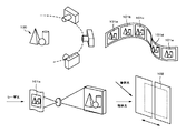
- a holographic stereogram uses a large number of images obtained by sequentially imaging a subject from different observation points as an original image, and sequentially exposes them as a strip or dot element hologram on a single hologram recording medium. It is made by recording.
- a holographic stereogram having parallax information only in the horizontal direction includes a plurality of original images 101a to 101e obtained by sequentially photographing the subject 100 from different observation points in the horizontal direction.
- the interference fringes generated by the interference between the object light and the reference light that are image-modulated by irradiating the displayed image with laser light are strip-shaped. It is manufactured by sequentially exposing and recording on the hologram recording medium 102 as an element hologram.
- the holographic stereogram produced in this way has image information obtained by sequentially capturing images from different observation points in the horizontal direction, and is recorded sequentially in the horizontal direction as strip-shaped element holograms.
- image information obtained by sequentially capturing images from different observation points in the horizontal direction, and is recorded sequentially in the horizontal direction as strip-shaped element holograms.
- a collection of image information recorded as a part of each element hologram is identified as a two-dimensional image, and another position different from this position
- the collection of image information recorded as the other part of each element hologram is identified as another two-dimensional image. Therefore, when the observer views the holographic stereogram with both eyes, the exposure recording image is recognized as a three-dimensional image by the parallax between the left and right eyes.
- various hologram display apparatuses are used as apparatuses for displaying hologram images for the purpose of viewing.
- an illumination device suitable for observing an image hologram or a holographic stereogram for viewing That is, as shown in FIGS. 6 and 7, by sequentially turning on a plurality of light sources from a predetermined position with respect to the hologram, it is possible to make a stereoscopic image appear to move to a stationary observer. it can.
- FIG. 7 shows a hologram reproducing apparatus 1000 incorporating the sound reproducing mechanism disclosed in FIG.
- the LED built in the main body 1003 is irradiated obliquely downward from a predetermined angle when the lid portion 1001 is opened.
- the main body incorporates an audio data storage device, an audio data amplification circuit, a speaker 1004, a battery 1006, an LED, an electronic circuit board 1007, and the like.
- a micro switch 1005 is arranged at a position where the main body is not conspicuous. When the lid is closed, the switch is pressed, and so-called power is turned off. When the lid is opened, the power is turned on by moving the switch to the open position.
- the lid 1001 is fixed at a predetermined angle ⁇ , for example, 115 ° by a stopper (not shown).
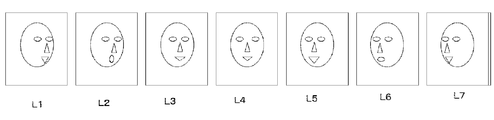
- a plurality of, for example, seven, LEDs are arranged in advance at different positions. By sequentially lighting the LEDs, it is possible to make it appear as if the hologram image is moving to a stationary observer.
- the positional relationship between the LED and the hologram is such that a central LED, L4 is arranged in an angle ⁇ , for example, 58 ° with respect to the normal from the center of the hologram, and a line connecting the center of the hologram and the central LED, L4.
- L1 to L3 and L5 to L7 are arranged so as to look at the center of the hologram at a different angle in the vicinity of the surface including.
- L1, L2, L3, L4, L5, L6, and L7 are turned on in order, so that the eyes of the person who is observing the hologram from almost the central normal direction.
- the hologram image frames of the recorded images are reproduced in the order of L1 to L7 in FIG. 8, and if it has a function of reproducing the stored audio data, the light lighting control speed is Synchronizing the audio playback speed is disclosed.
- Patent Document 2 discloses a hologram in which a different stereoscopic image can be seen depending on the viewing direction as a screen switching type, but it is not an image for authentication.
- Patent Document 3 discloses a hologram recording film with additional information, but it is not limited in view angle and is not like a barcode premised on machine reading.
- Patent Document 4 discloses a medium in which a management number can be seen only from a certain limited angle for the purpose of facilitating management in the printing process of the holographic stereogram, but it is not authentication information, Moreover, it was not the premise information that machine reading was possible.
- Patent Document 5 discloses a type of medium in which individual ID information can be observed as a hologram from a certain limited angle.
- the hologram cannot be observed unless the angle of illumination light is specified as well as the position of imaging, it is difficult for a person who does not have basic knowledge to carry out machine reading without fail in a short time.
- Patent Document 6 discloses an example in which an optical guide is displayed from an image sensor in order to limit the imaging position when reading a hologram having a narrow reproduction directivity angle.
- an optical guide is displayed from an image sensor in order to limit the imaging position when reading a hologram having a narrow reproduction directivity angle.
- Patent Document 7 in order to read the character information of the hologram recorded in the manufacturing inspection process, an example in which a partial captured image is synthesized by time-division illumination from a plurality of LED light sources arranged close to the hologram Is disclosed.
- this conventional example is a technique for making it possible to read a hologram recorded in the back or near side of the hologram surface with an adjacent light source, and so-called multiple images are reproduced when simultaneously illuminating from different light sources. This is effective for removing crosstalk, but when a barcode is printed on the hologram surface, multiple images are not reproduced in the first place and crosstalk does not occur. When it was used to make it stronger, it was necessary to add another element that could not be easily reverse engineered.
- JP 2008-122670 A “Screen Switching Hologram Manufacturing Method and Screen Switching Hologram Manufactured Using the Method” JP-A-11-258970 “Hologram recording film with additional information and recording method thereof” JP 2001-337588 A “Hologram printing system and holographic stereogram” JP 2010-176116 A “Image Recording Medium, Hologram Duplicating Apparatus and Method” Japanese Patent Application Laid-Open No. 2012-145612 “Optical Reader Module and Optical Reader” JP 2010-250191 A “Hologram Reproduction and Imaging Device, Hologram Reproduction and Imaging Method”
- Bar code information can be easily obtained from a portable information terminal such as a smartphone, portable game machine, or portable music player using a hologram medium on which a machine-readable barcode is superimposed and recorded when illuminated at a certain wavelength from a certain angle. Make it readable. Since the hologram cannot be easily forged, it can be used as a key that cannot be accessed unless the hologram medium is owned. Since many portable information terminals have an imaging device and a communication connection means to the Internet, various functions can be added without significant cost increase only by adding software.
- a barcode that can be imaged and decoded from the direction directly opposite the hologram is recorded on a part of the viewing hologram only when illuminated with illumination light of a specific direction and wavelength, and the light source that illuminates the hologram and the imaging device that images And the like, and an advanced authenticity determination is performed by analyzing a reproduced image obtained according to the change.
- a hologram-containing medium for example, by attaching a hologram-containing medium to an illumination device and controlling illumination in the illumination device from a smartphone or other terminal, authentication can be performed based on whether or not image information corresponding to illumination can be captured by the smartphone. I found the algorithm.
- the image information is preferably a two-dimensional barcode or the like that can determine whether or not the image information can be clearly recognized.
- the imaging apparatus performs decoding at a constant interval, and it is only necessary to determine whether the hologram actually exists by determining in real time whether or not the illumination light source can be switched and decoded. Even if a regular bar code is printed by hard copy, the captured image does not follow when illuminated from various directions.
- the authenticity determination function is further strengthened.
- the hologram has a function to accurately reproduce the above, it is difficult to produce the same image as a regular hologram unless it can be sensed three-dimensionally. Even if it is possible, it takes time to sense and generate an image corresponding to it and display it on the monitor. Therefore, it is significant to determine whether the captured image follows by switching the illumination light at high speed.
- the authentication algorithm, parameters, light emission control timing, etc. may be stored in the imaging device or lighting device, but for higher security, these are supplied from a remote server and changed accordingly. It can also be done.
- an algorithm was also invented that can be decoded not only in combination with an illuminating device but also in a mobile information terminal alone having an imaging element such as a smartphone and an imaging illumination light source. That is, the positional relationship among the light source, the image sensor, and the hologram is changed by shaking the smartphone held by hand to the left and right. At that time, the information recorded in the hologram was successfully read out by analyzing the captured image.
- the present invention is a method of performing image recognition using an information processing apparatus having an image sensor and a hologram, and creates at least two states in which the relative position relationship between the hologram medium, the light source, and the image sensor, or the light emission state of the light source is different.
- the above-described problem is solved by providing an image creation method including a procedure and a procedure for the information processing apparatus to acquire the image information in the different state from the image sensor.
- the present invention includes a procedure for comparing the information obtained by the above procedure with the information recorded in the hologram that is the recognition medium and determining the authenticity of the hologram in the image recognition method.
- the above-mentioned problem is solved by providing the image recognition method described in paragraph 0032, which is characterized.
- the present invention provides a procedure for sending information obtained by the above procedure to another apparatus in the image recognition method, and a procedure for obtaining a result compared with information recorded in a hologram as a recognized medium.
- the above problem is solved by providing an image recognition method according to paragraph 0032, which includes a procedure for performing different operations depending on the result.
- the present invention also provides the image recognition method according to paragraph 0032, wherein the image recognition method further includes a step of reading information recorded by a non-hologram method arranged near the hologram. This solves the above problem.
- the present invention provides the image recognition method according to paragraph 0032, wherein the image recognition method further includes a procedure for storing the unique ID information of the information processing apparatus including the image sensor together with the image information. This solves the above problem.
- the hologram reproducing apparatus having a light source can be separated from the procedure for holding the medium so that the relative positional relationship between the light source and the hologram medium is determined, and the hologram reproducing apparatus. Analyzing or decoding at least two images obtained by a procedure for controlling a light source in the hologram reproducing device and an image sensor arranged in the information processing device in a state where the information processing device is substantially stationary, The above problem is solved by providing an image recognition method according to paragraph 0032 including a procedure for performing authenticity determination of the hologram medium.
- the information processing apparatus analyzes a procedure for controlling light emission of at least two light sources arranged in the hologram reproducing apparatus, and an object change of a captured image is analyzed accordingly. Then, the above problem is solved by providing an image recognition method according to paragraph 0032, wherein authentication is performed.
- the hologram medium uses at least one authentication image code printed in a holographic manner, and the information processing apparatus performs a predetermined sampling interval with respect to the hologram medium.
- the authenticity determination is performed by at least one of the procedure for setting the image receiving state in step 1, the fact that decoding is possible when a predetermined light source is irradiated, decoding is not possible when a predetermined light source is not irradiated, and decoding is not possible when a plurality of light sources are simultaneously irradiated.
- the hologram medium is substantially stationary using a hologram medium printed with a hologram on which at least two different authentication image codes are reproduced under different illumination conditions.
- the method according to paragraph 0032 including a procedure for setting a focus using an imaging device to enter an image receiving state, a procedure for issuing a command to emit a different light source, and a procedure used for authenticity determination that the authentication image code information can be read accordingly.
- the present invention uses the medium in which the authentication image code is encrypted and recorded in the image recognition method, and creates at least two states in which the positional relationship between the illumination light, the medium, and the image sensor is different.
- Paragraph 0032 including a procedure for imaging, a procedure for reconstructing the captured partial region to regenerate one authentication image code, and a procedure for decoding from the regenerated authentication image code
- the information processing apparatus having an image sensor is a portable information terminal having a light source, and the procedure for controlling the light source and the entire portable information terminal are moved relative to the hologram medium.
- the information processing apparatus having an image sensor is a portable information terminal having a light source, and at least one detection value of an acceleration sensor or a gyro sensor built in the portable information terminal is obtained.
- the above problem is solved by providing an image recognition method according to paragraph 0042 including a procedure for obtaining and a procedure for using the obtained detection value for image analysis.
- the information processing apparatus having an image sensor has a communication means with an authentication server in a remote place, information on light emission control to the hologram reproduction apparatus, a captured image, and a decoded converted image.
- the above problem is solved by providing an image recognition method according to paragraph 0032, which includes a procedure for transmitting / receiving information such as data contents and time required for decoding to / from a server.
- the present invention also provides a procedure for reading a marking image displayed on a hologram medium, on a hologram surface, or on a nearby substrate by printing or processing using a method that is not holographic.
- the image according to paragraph 0032 further comprising: a procedure for estimating a hologram medium position from information obtained from the marking image; and a procedure for capturing or decoding a hologram image by limiting a region from the estimated information.
- the marking printed by two-dimensional printing is composed of a barcode
- the information processing apparatus decodes the barcode, and the focus is fixed when the decoding is completed.
- the present invention also provides a procedure for displaying an image captured by the image sensor on the display device in real time and a procedure for turning on the light source in an information processing apparatus having an image sensor, a light source, and a display device. And a procedure for displaying the first guide mark on the display device, and the guide mark on the display device is displayed on the hologram medium, on the hologram surface, or on the base material by non-holographic printing or processing.
- a procedure for prompting to match the first marking image, a procedure for displaying the second guide mark on the display device after reading the first hologram information, and a second on the hologram surface or in the vicinity of the base material is solved by providing an image recognition method according to paragraph 0032 including a procedure for prompting to match the marking images.
- an image recognition method described above in an information processing apparatus having an image sensor, a light source, and a display device, a procedure for transmitting model data of the information processing device to a storage device, and guide marks displayed on the display device.
- the image of the holographic barcode on the image sensor when the holographic barcode can be decoded, or parameter information such as the position and angle obtained therefrom is stored in the storage device.
- the above problem is solved by providing an image recognition method according to paragraph 0047, which includes a transmission procedure.
- the invention of the present application is a medium in which an authentication image code is recorded in a holographic manner, and when the same position on the medium surface is irradiated with light from different angles, at least two independent authentication image codes, or
- the above-described problem is solved by providing a medium in which a part of the authentication image code is recorded so as to be reproduced.
- the present invention is a medium in which an authentication image code is recorded in a holographic manner, and when irradiated with light of different wavelengths at the same position on the medium surface, at least two independent authentication image codes, or
- the above-described problem is solved by providing a medium in which a part of the authentication image code is recorded so as to be reproduced.
- the present invention solves the above problem by providing an authentication image code recorded medium of paragraph 0050 or paragraph 0051 in which the medium cannot be decoded by a kind of illumination light from one direction.
- a marking image is displayed on the hologram medium, on the hologram surface, or on a nearby substrate by printing or processing using a method other than holographic methods.
- the above problem is solved by providing the described medium.
- the present invention solves the above-mentioned problem by providing the image recording medium according to paragraph 0053, wherein the marking image is an authentication image code in the image recording medium.
- the invention according to paragraph 0054 is characterized in that, in the image recording medium, a symbol indicating a direction in which the image sensor and the medium should be moved relatively is printed when the authentication image code is read.
- the present invention also provides the image recording medium according to paragraph 0054, wherein at least one of the marking image and the holographic authentication image code is printed with a trapezoidal distortion in the image recording medium. This solves the above problem.
- the present invention also provides the medium according to paragraph 0050 or paragraph 0051, wherein an image for viewing different from the holographic authentication image code is formed on the same medium in the image recording medium. This solves the above problem.
- the present invention also relates to the above-described image recording medium, wherein the image recording medium includes a partition belt, a housing that can store the partition belt, a part of a partition stand that can be installed upright on a floor provided with the housing, or the partition.
- the image recording medium includes a partition belt, a housing that can store the partition belt, a part of a partition stand that can be installed upright on a floor provided with the housing, or the partition.
- the invention of the present application is characterized in that the hologram reproducing device has a communication means and controls light emission of the light source in accordance with an external control signal or transmits a control signal for controlling light emission of the light source to another device.
- the present invention provides an apparatus for reading a medium in which an authentication image code is recorded in a holographic manner, either an optical opening for combining an imaging lens unit or an optical opening for combining the holographic code portion.
- an information reading device in which both or both optical openings are formed.
- the invention of the present application is characterized in that, in the above information reading apparatus, the image reading element fixed inside and a portable information terminal incorporating a light source, and an optical opening for bringing the hologram medium close to each other are provided.
- the above problem is solved by providing the described medium.
- the invention of the present application is characterized in that in the above information reading apparatus, the medium has a holographic barcode medium fixed therein and an optical opening for bringing the imaging lens portion of the portable information terminal close to each other.
- the above problem is solved by providing the described medium.
- the line connecting the center of the medium of the holographic barcode and the opening of the imaging lens unit is substantially symmetric with respect to the medium normal of the holographic barcode or the optical line thereof.
- an authenticity determination function can be added to the viewing hologram.
- music bonus tracks and voice messages that cannot be accessed without an actual hologram can be downloaded to a smartphone or a storage device built in the hologram playback device, or special character content for games can be obtained. Additional functions can be provided.
- the present invention is applied to a system, a method, a medium, and an apparatus for adding an additional function to a hologram or holographic stereogram medium.
- a holographic stereogram will be specifically described as an example of a hologram or a holographic stereogram attached to these devices prior to description of devices to which the present invention is applied.
- the hologram recording medium 3 is a recording layer made of a photopolymerizable photopolymer on a base film 4 which is a support material made of, for example, polyethylene terephthalate (hereinafter referred to as PET) film.
- PET polyethylene terephthalate
- a photopolymer layer 5 is formed, and a cover film 6 made of, for example, a PET film is deposited on the photopolymer layer 5 to form a so-called film coating type recording medium.
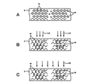
- the photopolymerization type photopolymer constituting the photopolymer layer 5 is in a state where the monomers M are uniformly dispersed in the matrix polymer in the initial state. is there.
- the photopolymerization type photopolymer is uniformly dispersed in the matrix polymer in the exposed portion when irradiated with laser light LA having a power of 10 mJ / cm @ 2 to 400 mJ / cm @ 2. Is polymerized into a polymerized state.
- the photopolymerization type photopolymer As the photopolymerization type photopolymer is polymerized, the monomer M moves from the surroundings to cause non-uniformity in the density of the monomer M, thereby causing a refractive index modulation between the exposed and unexposed areas. Thereafter, as shown in FIG. 2C, the photopolymerization type photopolymer is irradiated with ultraviolet rays or visible light LB having a power of about 1000 mJ / cm 2 to complete the polymerization of the monomer M in the matrix polymer.
- the photopolymerization type photopolymer constituting the photopolymer layer 5 changes its refractive index according to the incident laser beam LA, so that the object beam and the reference beam The interference fringes generated by the interference are recorded by exposure as changes in the refractive index.
- the hologram recording medium 3 is configured as a so-called film coating type recording medium, a step of performing a special development process after exposure recording is not required. Therefore, by recording a hologram image using such a hologram recording medium 3, a structure for performing a development process in the holographic stereogram manufacturing apparatus becomes unnecessary, the apparatus configuration can be simplified, and the holographic structure can be simplified. Stereograms can be made quickly.
- a holographic stereogram having parallax information in the horizontal direction is produced by exposing and recording a plurality of strip-shaped element holograms on one hologram recording medium 3.
- the holographic stereogram may have parallax information in the horizontal and vertical directions by, for example, exposing and recording a plurality of dot-shaped element holograms on one hologram recording medium. Not too long.
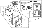
- the holographic stereogram manufacturing apparatus 10 exposes and records a holographic stereogram image on a hologram recording medium 3 made of a photosensitive film.
- the holographic stereogram production apparatus 10 includes an image data processing unit 11 that processes image data to be exposed and recorded, a control computer 12 that comprehensively controls the holographic stereogram production apparatus 10, and a holographic stereogram. And a holographic stereogram production unit 13 having an optical system for production.
- the image data processing unit 11 includes at least an image processing computer 14 and a storage device 15. For example, captured image data including parallax information supplied from a parallax image sequence imaging device 1 having a multi-lens camera, a mobile camera, or the like.
- a parallax image data sequence D3 is generated based on image data such as D1 and computer image data D2 including parallax information generated by the image data generation computer 2.
- the captured image data D1 is a plurality of image data obtained by, for example, simultaneous shooting with a multi-lens camera or continuous shooting with a mobile camera, and disparity information is included between the image data constituting the captured image data D1. included.
- the computer image data D2 is a plurality of image data created as, for example, CAD (Computer Aided Design) or CG (Computer Graphics), and disparity information is included between the image data constituting the computer image data D2. .
- the image data processing unit 11 performs predetermined image processing for the holographic stereogram by the image processing computer 14 on the parallax image data sequence D3 based on the captured image data D1 and / or the computer image data D2.
- Hologram image data D4 is generated.
- the hologram image data D4 is temporarily stored in a storage device 15 such as a memory or a hard disk device.
- a storage device 15 such as a memory or a hard disk device.
- the image data processing unit 11 when the image data processing unit 11 exposes and records an element hologram image on the hologram recording medium 3, the image data processing unit 11 performs element hologram images for each image from the hologram image data D4 stored in the storage device 15.
- Data D5 is sequentially read out, and the element hologram image data D5 is supplied to the control computer 12.
- the control computer 12 controls the holographic stereogram producing unit 13 so that the element display image based on the element hologram image data D5 supplied from the image data processing unit 11 is part of the holographic stereogram producing unit 13.
- the hologram recording medium 3 provided is sequentially exposed and recorded as strip-shaped element holograms. At this time, the control computer 12 controls the operation of each mechanism of the holographic stereogram production unit 13 as described later.
- each member constituting the optical system is disposed and supported on a support substrate (optical surface plate) (not shown), and this support substrate is supported on the apparatus housing via a damper (not shown).
- the structure is made.
- the holographic stereogram producing unit 13 includes an incident optical system, an object optical system, and a reference optical system as an optical system for producing the holographic stereogram. Since the holographic stereogram manufacturing apparatus 10 uses the hologram recording medium 3 that is a photosensitive material, the apparatus housing has a structure that retains at least the light shielding property of the optical system.
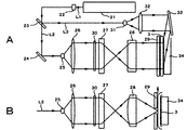
- the holographic stereogram preparation unit 13 is arranged as an incident optical system on a laser light source 21 that emits laser light of a predetermined wavelength and on the optical axis of the laser light L1 from the laser light source 21.
- the shutter mechanism 22 that makes the laser beam L1 incident or blocked at the subsequent stage and the half mirror 23 that divides the laser beam L1 into the object beam L2 and the reference beam L3.
- the laser light source 21 is composed of a laser device such as a semiconductor-excited YAG laser device, a water-cooled argon ion laser device, or a water-cooled krypton laser device that emits laser light L1 having a single wavelength and good coherence.
- a laser device such as a semiconductor-excited YAG laser device, a water-cooled argon ion laser device, or a water-cooled krypton laser device that emits laser light L1 having a single wavelength and good coherence.
- the shutter mechanism 22 is opened / closed by a control signal C1 output from the control computer 12 in response to the output timing of the element hologram image data D5, and causes the laser light L1 to enter a subsequent optical system. Alternatively, the incidence on the subsequent optical system of the laser beam L1 is blocked.
- the half mirror 23 divides the incident laser light L1 into transmitted light and reflected light.
- the laser light L1 uses the transmitted light as the above-described object light L2, while the reflected light is used as the reference light L3.
- the object light L2 and the reference light L3 are incident on an object optical system or a reference optical system provided in the subsequent stage.
- the incident optical system may be provided with a mirror or the like for the purpose of changing the traveling direction of the laser light L1 as appropriate so that the optical path lengths of the object light L2 and the reference light L3 are the same.
- the shutter mechanism 22 may be configured, for example, such that the shutter piece is mechanically driven or an electronic shutter using an acousto-optic modulator (AOM). . That is, the shutter mechanism 22 only needs to be openable and closable so as to shield and transmit the laser light L1.
- AOM acousto-optic modulator
- the holographic stereogram preparation unit 13 includes a mirror 24, a spatial filter 25, a collimator lens 26, a projection lens 27, a cylindrical lens 28, a mask 29, and the like as an object optical system.
- a mirror 24, a spatial filter 25, a collimator lens 26, a projection lens 27, a cylindrical lens 28, a mask 29, and the like as an object optical system.
- Each of these optical components is sequentially arranged from the input side along the optical axis.
- the mirror 24 reflects the object light L ⁇ b> 2 that has passed through the half mirror 23.
- the object light L ⁇ b> 2 reflected by the mirror 24 is incident on the spatial filter 25.
- the spatial filter 25 is configured by combining, for example, a convex lens and a pinhole, and isotropically reflects the object light L2 reflected by the mirror 24 in accordance with the display surface width of a transmissive liquid crystal display 30 described later. Enlarge.
- the collimator lens 26 converts the object light L ⁇ b> 2 expanded by the spatial filter 25 into parallel light and guides it to the transmissive liquid crystal display 30.
- the projection lens 27 slightly diffuses the object light L 2 and projects it onto the cylindrical lens 28.
- the projection lens 27 contributes to improving the image quality of the produced holographic stereogram by slightly diffusing the object light L2.
- the cylindrical lens 28 condenses the collimated object light L2 in the lateral direction.
- the mask 29 has a strip-shaped opening, and the object light L 2 collected by the cylindrical lens 28 that has passed through the opening is incident on the hologram recording medium 3.
- a transmissive liquid crystal display 30 is disposed between the collimator lens 26 and the projection lens 27. Element hologram images are sequentially displayed on the transmission type liquid crystal display 30 based on the element hologram image data D5 supplied from the control computer 12.
- the control computer 12 supplies a drive signal C2 to the recording medium feed mechanism 34 of the hologram recording medium 3 to be described later in response to the output timing of the element hologram image data D5, and controls the operation thereof.
- the feeding operation of the hologram recording medium 3 is controlled.
- the object light L2 that is in the form of a thin beam divided and incident from the incident optical system is magnified by the spatial filter 25 and incident on the collimator lens 26 to be converted into parallel light. Is done.
- the object light L 2 incident on the transmissive liquid crystal display 30 via the collimator lens 26 is image-modulated according to the element hologram image displayed on the transmissive liquid crystal display 30. At the same time, it enters the cylindrical lens 28 via the projection lens 27. Then, the object optical system causes the image-modulated object light L2 to enter the hologram recording medium 3 through the opening of the mask 29 while the shutter mechanism 22 is opened, and corresponds to the element hologram image. This is recorded by exposure.
- the holographic stereogram preparation unit 13 includes a spatial filter 31, a collimator lens 32, and a mirror 33 as a reference optical system, and these optical components are sequentially arranged from the input side along the optical axis. Yes.
- the spatial filter 31 is configured by combining, for example, a cylindrical lens and a slit, and the reference light L3 reflected and divided by the half mirror 23 has a predetermined width, specifically First, it is enlarged in a one-dimensional direction corresponding to the display surface width of the transmissive liquid crystal display 30.
- the collimator lens 32 converts the reference light L3 magnified by the spatial filter 31 into parallel light.
- the mirror 33 reflects the reference light L3, guides it to the rear of the hologram recording medium 3, and makes it incident.
- the holographic stereogram preparation unit 13 including such an optical system includes an object optical system that is an optical system through which the object light L2 divided by the half mirror 23 passes and a reference optical that is an optical system through which the reference light L3 passes.
- the optical path length with the system is almost the same. Therefore, the holographic stereogram producing unit 13 can produce a holographic stereogram in which the coherence between the object light L2 and the reference light L3 is improved and a clearer reproduced image can be obtained.
- the holographic stereogram production apparatus 10 includes a recording medium feeding mechanism 34 that intermittently feeds the hologram recording medium 3 by one element hologram in the direction indicated by the arrow in FIG. 4B.
- the recording medium feeding mechanism 34 intermittently drives the hologram recording medium 3 based on the drive signal C ⁇ b> 2 supplied from the control computer 12. Further, in the holographic stereogram producing apparatus 10, the above-described shutter mechanism 22 is operated based on the control signal C1 supplied from the control computer 12 in conjunction with the operation of the recording medium feeding mechanism 34, and the laser light L1. Open the light path.
- Such a holographic stereogram production apparatus 10 is supplied with a drive signal C2 corresponding to a one-element hologram from the control computer 12 to the recording medium feeding mechanism 34 every time exposure recording for one element image is completed. Then, the hologram recording medium 3 is driven to travel along the travel path by an amount corresponding to the one-element hologram, and the unexposed part is made to correspond to the opening of the mask 29 and stopped.
- the holographic stereogram manufacturing apparatus 10 is configured such that vibration generated in the hologram recording medium 3 in accordance with the traveling operation of the hologram recording medium 3 is quickly stopped.
- the hologram recording medium 3 is made of a long photosensitive film and is wound around a supply roll that is rotatably provided inside a film cartridge that is held in a light-shielded state, for example, although not shown. Yes.
- the film cartridge is loaded into the holographic stereogram manufacturing apparatus 10
- the hologram recording medium 3 is fed into the holographic stereogram manufacturing apparatus 10 and is driven to travel along the traveling path by the recording medium feeding mechanism 34. .
- the holographic stereogram manufacturing apparatus 10 opens the shutter mechanism 22 to provide the hologram recording medium 3 with the object light L2 and the reference light L3 that are image-modulated from the front and back surfaces of the hologram recording medium 3.
- the interference fringes corresponding to the element hologram image are recorded by exposure.
- the holographic stereogram production apparatus 10 is supplied with a drive signal C2 from the control computer 12 to the recording medium feeding mechanism 34 when the exposure recording of the one-element image is completed, and travels the hologram recording medium 3 quickly by a predetermined amount. Drive and stop.
- the holographic stereogram manufacturing apparatus 10 performs a fixing process including an ultraviolet irradiation process on the hologram recording medium 3 and a heating process on the hologram recording medium 3 at a predetermined temperature by a fixing processing unit (not shown). A holographic stereogram image exposed and recorded on the hologram recording medium 3 is fixed.
- the holographic stereogram production apparatus 10 sequentially cuts out the hologram recording medium 3 on which the fixing process has been performed into a predetermined size for each holographic stereogram image, and discharges it as a single holographic stereogram to the outside.
- the holographic stereogram manufacturing apparatus 10 sequentially performs this operation below, thereby sequentially exposing and recording a plurality of holographic stereogram images on the long hologram recording medium 3, thereby producing one holographic stereogram.
- a holographic stereogram in which a gram image is recorded by exposure is prepared.
- a specific example of a holographic stereogram constructed by applying the present invention and created as described above, a medium to which various holograms are attached, and a lighting device therefor will be described.
- the various holograms are not limited to the Lippmann type (volume type) one-step holographic stereogram with lateral parallax as described above, but a full parallax stereogram with vertical parallax added, a live-action hologram taken by laser irradiation of a model, etc. Also included are holograms replicated using them as masters, so-called embossed holograms of surface relief type, diffraction gratings and the like.
- a holographic stereogram is also included in a hologram as a kind of hologram.
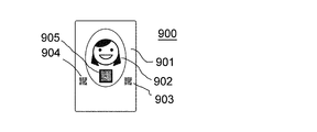
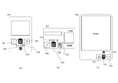
- FIG. 9 shows an example medium 900 to which the present invention is applied.
- a hologram 902 made by the above-described process is formed on a part or all of a credit card size medium 901 having a thickness of about 1 mm, a length of 85.4 mm, and a width of 54 mm.
- an image obtained by converting information at the position illustrated in 905 into a two-dimensional barcode is reproduced when illuminated from about 45 ° diagonally to the left and 30 ° obliquely downward.
- another bar code is reproduced at the same place.
- two other barcodes 903 and 904 are printed on the substrate of the medium.
- FIG. A slot into which a part of the medium 900 described in FIG. 9 can be inserted is formed on the base 913 of the image reproducing device 950.
- FIGS. A cross section and an XX cross section are also illustrated.
- Power can be supplied by connecting a household AC power source to the inlet 910.
- a dry battery or a rechargeable battery may be built in without supplying power from the outside, or power may be supplied from a smartphone or the like.
- the LED can be driven and controlled from the smartphone side by wire.
- L1 to L7 are controlled so that they are sequentially turned on one by one, it is possible to show a moving stereoscopic image to a non-moving observer that faces the hologram.
- L1 to L7 may be turned on in reverse order as L7, L6... L1, or may be turned on repeatedly as L1, L2.
- the light source can be controlled from the smartphone side, there is a great merit that the rendering effect can be enhanced in conjunction with various applications from the smartphone side.
- the smartphone can be charged by connecting with the USB cable, there is also an advantage that it is easy to enjoy viewing the hologram while charging.
- the AC adapter for charging the smartphone has a hologram reproduction function.
- a secondary battery such as lithium ion
- it can also function as a mobile battery, and can be added with a function that allows users to view holograms without always supplying AC power.
- the mobile battery has a hologram playback function.
- the image playback apparatus has a built-in speaker 915, so that music and audio content can be listened not only to the smartphone but also from the image playback apparatus.
- the image playback device is equipped with a storage device such as a memory or hard disk
- the content downloaded by the smartphone can be transferred to the image playback device and saved, so that the image playback device alone can be used without a smartphone.
- sound reproduction can also be performed.
- the image playback apparatus may not have a storage device, and audio data or the like may be transferred from the smartphone side in real time.
- the light source control signal and the audio data may be sent from the smartphone to the hologram reproducing device by a wired connection via a USB cable or the like, Bluetooth (registered trademark), WiFi (registered trademark), infrared, NFC, etc. It may be connected by non-contact communication means. Power can be supplied wirelessly.
- the smartphone has software with the following functions.
- A-1 Capture and decode 2D printed barcode information on a medium using an image sensor mounted on a smartphone.
- A-2. Fix the autofocus function of the image sensor at the stage where it was decoded.
- A-3. Determine the known holographic barcode imaging area based on the relative relationship with the position where the barcode was printed. Sampling starts at regular intervals within the area.
- A-4: A command to illuminate the L1 light source is issued to the holographic image reproducing apparatus.
- A-6 If it still cannot be decoded, the user is notified of the abnormality. If A-6 can be decoded, a command to illuminate the L7 light source is issued, and the same operations as in A-3 to A-5 are performed.
- A-7 The process proceeds to the next process based on the information decoded by A-5 and A-6. For example, if URL information that has not been disclosed by other means or encrypted password information is included in the decoded content, since it cannot be accessed without possessing this medium, an authentication function can be added. become. Although seven light sources from L1 to L7 have been described, any number of light sources can be applied. In order to effectively express the continuity of holographic stereogram images, the number may be increased to about 30 to 100.
- the positional relationship between the smartphone and the hologram medium may not be in a predetermined state. In that case, it is possible to try decoding by irradiating an adjacent light source such as irradiating L2 instead of L1. Alternatively, since it becomes easier to decode when the smartphone is slightly moved, that fact may be communicated to the operator by screen display or by voice.
- three or more types of barcodes recorded in a holographic manner may be printed, and a corresponding reproducing apparatus may be provided with more than that number of light sources. A higher number can provide a higher level of security functions.
- lenticular photography As a medium similar to a hologram, there is a technique called lenticular photography. In other words, different information and stereoscopic images are reproduced as multi-viewpoint images when viewed from different angles due to the lens-like lens effect. However, even if the illumination light is changed, the image seen from the front may change. Absent. That is, a phenomenon peculiar to holograms is used. Holograms must be counterfeited due to the fact that they can be recorded at a much higher density than ordinary printing media and lenticular photography, cannot be easily created, and have limited materials and devices. Is difficult.
- the algorithm for authenticity determination is not limited to the above, and various patterns are conceivable. If they are encrypted, and if software or libraries based on the authentication algorithm are supplied from the host server using a network, even if one algorithm is overlooked, the authentication function will be provided by a new algorithm. It is easy to update.
- two different barcodes can be recognized from two directions, but this number may be 1 or 3 or more.
- the authenticity determination function becomes more robust. This is because a malicious person, for example, installs a light receiving element in a lighting device, encodes a barcode image that should be reproduced as a hologram, displays it on another display in real time, and reads it with a smartphone for decoding This is because it is difficult to accurately detect from which direction the light is shining even when trying to do this.
- the order of light emission is not limited to the order of L1 ⁇ L4 ⁇ L7, but can be changed in any way, and if it is changed for each determination, it can be a measure against forgery.
- a light source with high-speed response characteristics such as an LED into an image reproducing device and using an image pickup device with high-speed response characteristics such as CMOS in the image pickup device, for example, switching to a high speed of 1 millisecond or less can be used for imaging. Even if the light source control method is reverse engineered, it is very difficult to disguise it with another light source in real time. If this is utilized, it is also possible to add to the point of authenticity determination.
- the conditions to be recorded in the hologram are defined and not disclosed. Various modifications can be considered by checking whether the recording condition and consistency can be taken based on the positional relationship between the light source and the imaging device during reproduction based on the conditions.
- Form (A) When a person who owns a portable hologram medium reads with a portable information terminal, Form (B) The information terminal for reading is fixed at a certain place, and the person who owns the hologram medium reads it at that specific place.
- the hologram card shows portraits of famous talents, animated characters, etc.
- you can listen to sound data related to the content that is, the voices of the talent and characters and bonus tracks. ing.
- the dedicated software on the smartphone can be downloaded if the user can obtain access right automatically without taking complicated steps in the process as described in A-1 to A-7 above. Become. Once downloaded, the data may be accessible anytime thereafter, or the access right may be determined each time it is listened to. Also, if the access right to the content that is updated every day is determined, the user can listen to new content data without being conscious of inputting a password or the like. If the light source for hologram illumination is sequentially turned on according to music and voice, it is possible to produce an effect as if speaking in synchronization with the hologram image. It is possible to increase the speed of flashing up-tempo songs in sequence, and to reduce the lighting speed in slow-tempo ballads.
- a medal-shaped hologram-related toy As another application to which the present invention is applied, a medal-shaped hologram-related toy will be described.
- the medal is affixed with a hologram of an animated character, and when it is attached to a wristwatch-shaped toy, the character's cry or name is reproduced as speech.
- a light source is built in an appropriate position in the toy, and the medal-shaped hologram portion is imaged with a portable game machine. If the portable game machine also has an image sensor and communication means, access to the data in the server that can be accessed only by the person who has this hologram by the same process as the combination of the hologram reproducing device and the smartphone as described above. It becomes possible to do.
- FIGS. 1-10 A second embodiment to which the present invention is applied will be described with reference to FIGS.
- the present invention it is possible to determine the authenticity of a hologram using a portable information terminal having an image sensor and an illumination light source without a special reproducing device.
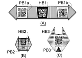
- a barcode as shown in Fig. 13 is two-dimensionally printed on the aforementioned music card, various certificates, pharmaceutical packages, brand product tags, etc., and a holographic barcode is affixed in part. .
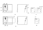
- a long arrow on the left and right and two-dimensional barcodes PB1a and PB1b on the left and right are printed by a normal two-dimensional printing method, and a barcode HB1 recorded in a holographic manner is pasted in the center.
- a holographic barcode HB2 and a two-dimensional printing barcode PB2 are arranged vertically in the arrows.
- FIG. 13A a long arrow on the left and right and two-dimensional barcodes PB1a and PB1b on the left and right are printed by a normal two-dimensional printing method, and a barcode HB1 recorded in a holographic manner is pasted in the center.
- a holographic barcode HB2 and a two-dimensional printing barcode PB2
- a large two-dimensional barcode is printed in an arrow, and a holographic barcode is affixed to the inside.
- the term “sticking” as used herein means that the medium including the hologram recording material layer is attached using a pressure-sensitive adhesive material or a heat-sensitive adhesive material, and desirably it cannot be separated from the substrate without destroying the hologram layer. It has become.
- the arrow indicates the direction of relative movement when reading the holographic barcode.
- the reason why the arrow image is composed of a fine texture is to make it easy to achieve autofocus of the image sensor.
- FIG. 13A A reading method in the example of FIG. 13A will be described with reference to FIG.
- an imaging device capable of high-speed photography and an illumination light source LED capable of high-speed driving are arranged approximately 10 mm apart.
- the smartphone In holding such a smartphone in landscape orientation and reading a holographic barcode.
- the hologram When an image of the printed barcode area is taken from the direction facing the medium, that is, from the normal direction, the hologram must read a reconstructed image with light incident at approximately 0 degrees, and the hologram surface is attached to the smartphone.
- the LED When the LED is illuminated, its direct regular reflection is incident on the image sensor, making it difficult to read the barcode.
- the image is tilted so as to aim at a depth of about 20 ° from the near side so that the regular reflection image does not enter.
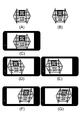
- FIG. 11A an image obtained by slightly adding a trapezoidal distortion as shown in FIG. 11B is actually printed.
- FIG. 11D shows a monitor image that can be seen on the screen of the smartphone.
- smartphones In general, smartphones often have an image sensor and a light source arranged on the opposite side of the monitor.
- the smartphone, and the holographic barcode In order to confirm that the holographic barcode is read on the monitor, it is easy to work intuitively if the user's eyes, the smartphone, and the holographic barcode are arranged in a substantially straight line in this order.
- the regular reflection of the hologram and the substrate enters the image sensor, making it difficult to read. Therefore, it is designed so that it can be read when tilted upward or downward by about 10 to 30 °. So far, the description has been made mainly on the assumption that reading is performed from below. This is easy to read when the card is placed on a table or the like.
- the direction of the medium shape of the holographic barcode is indicated so that the direction of the medium can be easily understood, as well as displaying the holographic barcode to be read from. Shaped. By doing so, there is also an effect of preventing a mistake in the upper and lower sides when pasting on a poster or a card.
- the base material of the holographic barcode was black to improve contrast. However, it may be made transparent so that what is printed on the lower surface can be seen through. In addition to the effect of maintaining design properties such as posters, it is also possible to print a two-dimensional barcode on the lower surface and read and decode both of them. If two-dimensional printing barcodes other than the holographic barcodes described in the present invention are superimposed on a plane, there is an effect of reducing the area required for this function, and the holographic barcodes have high adhesive strength. If it is pasted to the base material with a transparent adhesive, the base material will be broken at the same time when the holographic barcode is peeled off, and a tamper evidence effect can be obtained.
- an image hologram of a device illuminated obliquely from below is arranged, and the holographic barcode is obliquely viewed from above What is recorded in a readable manner will be described.
- the appreciation device does not require communication means and can be configured simply.
- the holographic bar code for reading information is not reproduced by the light source for viewing images, there is also an advantage that even if it is printed on the same material as the image hologram, it does not interfere with viewing.
- B-1 Hold the smartphone to the user and tell by voice or on-screen message to align the PB1a into a square in the frame of (D) (a).
- B-2 (D) Decode barcode in frame (a)
- B-3 Temporarily fix autofocus after decoding is completed
- B-4 Have holographic barcode in area (D)
- B-5 Tell the user by voice or on-screen message to move the smartphone to the right and align PB1b into a square within the frames of (E) and (c).
- the holographic barcode in the areas (E) and (b) is imaged at a certain sampling interval and read in the decode B-4, and the holographic barcode read in B-6
- the data of the graphic barcode can be made different because it is a hologram although it is data that can be decoded from the same area on one medium.
- the information of the holographic bar code changes every moment during the range in which the screen does not deviate, that is, during the reciprocation between the states (D) and (F).
- one barcode can be obtained by cutting out and reconstructing the barcode portion from the positional relationship of a plurality of holograms, light sources, and image sensors, and decoding the hologram It becomes possible to read the information recorded in the machine.
- the moving image barcode is recorded as a hard copy, and encrypted information can be obtained by performing reading while controlling the light source of the portable information terminal.
- iOS and Android smartphones are equipped with acceleration sensors, gyro sensors, etc., and their detection values can be used. For example, during a swinging reciprocating motion, it is possible to turn on the light source only when moving in one direction and to turn off the light source when moving in the opposite direction. By doing so, it is possible to detect the contrast of the barcode recorded in the holographic manner.
- Embossed holograms and Lippmann holograms have different appearances when the illumination is turned off or when illuminated with a monochromatic light source. Assuming that the Lippmann hologram is a regular one, even if it is forged by an embossed hologram, it can be excluded as a fake. In the case of a Lippmann hologram, light other than the light that meets the Bragg diffraction conditions is transmitted and absorbed by the back substrate, etc., whereas in the case of an embossed hologram, the transmitted light is reflected by the silver reflective layer on the back. Therefore, the difference can be proved by analyzing the captured image.
- the Lippmann method when illuminating a hologram that should reproduce a green hologram with a red LED, the Lippmann method is not reproduced at all, whereas the embossed method is reproduced only with a different diffraction direction. It will be.
- the barcode may be a barcode printed with the same information in content units or product units by a mass duplication method, or may be one that does not have the same two individual IDs. Individual IDs and serial numbers can be used not only for authenticity determination, but also for tracking and traceability systems. Although the holographic barcode may be an individual ID, it is possible to utilize the authenticity determination function together with the fact that the holographic barcode is not easily counterfeited only by making the two-dimensional printing barcode an individual ID.
- the portable information terminal When it swings at high speed, it may be difficult to read due to difficulty in focusing or image blurring. Therefore, first, the portable information terminal is focused on a marking image that is two-dimensionally printed in the vicinity of the hologram. Thereafter, by reducing the shutter speed and picking up an image at a high frame rate of about 240 fps, the sharpness of the picked-up image increases. The sharpness can be increased by turning on / off the LEDs at high speed without increasing the shutter speed or imaging at a high frame rate.
- the portable information terminal is read at an angle of about 15 ° to 20 ° with respect to the surface on which the two-dimensional marking or the holographic barcode is printed or pasted.
- the light source for flash purposes is often located in a location that is not far away from the image sensor.
- the light regularly reflected by the light source on the front and back surfaces of the hologram medium is directly incident on the image sensor, making it difficult to capture an image with good contrast. If the angle is too steep, it will be difficult to read the barcode. Therefore, a hologram Fic barcode that can be imaged at an angle of about 10 ° to 45 ° is recorded. In the examples of FIGS.
- FIG. 15 shows an example in which the holographic barcode is in a sticker shape and is affixed to the card. However, since the cut-out shape as the sticker is on the arrow, it is a type that images from obliquely below. You can understand this intuitively.
- a square frame is displayed on the screen of the smartphone so that the two-dimensional print barcode is aligned.
- this shape and method are not necessarily required.
- two or more two-dimensional barcodes and symbol marks are formed instead of one, and the positional relationship can be image-processed to be used as orientation information of the portable information terminal.
- a two-dimensional barcode is used as a marking image for aligning the position of the smartphone, it is not necessary to be limited to this.
- the image may be an image in which the positional relationship with the imaging element can be easily obtained by image processing. For example, if a grid-like image is printed in two dimensions, it is possible to know the relative position and relative angle between the portable information terminal and the hologram by analyzing the trapezoidal distortion of the captured image. It can be determined whether the obtained hologram image is normal. If the marking image is a fine image with high contrast, there is an advantage that focusing is easy.
- the texture in the arrow in FIG. 13A can also be used for this purpose.
- the marking image it is also possible to use a marking image in which a reading order such as 1, 2 is written in a square.
- the quadrangular shape is preferably a trapezoidal shape considering trapezoidal distortion. That is, the first marking guide 151, the second marking guide 152, and the two-dimensional barcode 154 are printed on the card 156 in the arrangement as shown in FIG. Is affixed on the card as a seal, and the shape of the seal is an upward arrow.
- the two-dimensional barcode is printed with black ink on a white background, whereas the holographic barcode is a green barcode on a black background.
- it may be formed by inverting negative or positive or in a different color.
- a figure drawn as 1 in a rectangle is displayed on the screen of the smartphone, and the figure and the image of the camera monitor of the smartphone are prompted to match.
- the size of ⁇ By adjusting the size of ⁇ , the distance between the smartphone and the hologram medium can be easily adjusted, and the printed rectangle is drawn slightly shorter on the lower side than the upper side.
- the marking shape is suitable.
- a figure drawn as 2 in a square is displayed on the smartphone screen and is guided so that the second code can be read easily.
- Smartphones or portable information terminals have different positions of the image sensor and the light source for each model.
- smartphones that use Android operating systems are designed by various manufacturers.
- whether or not the holographic bar code can be read properly depends on the positional relationship between the light source and the image sensor, and therefore the guide display for easy reading needs to be changed for each model. Since models with different specifications will be released one after another in the future, the present invention devised the following operation based on this.
- a series of flowcharts is shown in FIG.
- the information on the own model is first sent from the application on the smartphone to the server on the network, it is checked against the list of registered models, and in the case of the registered model, the recommended guide marking position coordinates are returned to the smartphone application.
- the smartphone app displays recommended guide markings. If it is not a registered model, information to that effect is sent from the server, so general guide markings that match the outline are displayed.
- the coordinate information is sent to the server when the user can read it over time. Thereby, information when it can be read can be collected and stored as a database. At this time, the time taken for reading is also sent to the server.
- the position coordinates of recommended guide markings are determined and added to the list of registered models together with model information. Including registered models, the position coordinates when 100% reading is successful and the time information required for successful reading are sent to the server. For example, the average of the top 5 points from the shorter reading time If automatic programming is performed so that the coordinates are listed as recommended guide marking coordinates, it is possible to provide a guide display that is easier to read without the need for manual analysis. If this system is used, there is an advantage that conditions that are easy to decode for each model can be automatically accumulated without experimenting and verifying an increasing number of portable information terminals by manpower and time.
- the hologram cannot be read by controlling the light source by utilizing the characteristics of the hologram. Simply, the hologram cannot be reproduced unless it is illuminated, so if it can be read without illuminating the light source, it can be judged as a fake. On the other hand, even if a plurality of light sources are irradiated, a plurality of images are overlapped and captured, so that the barcode cannot be decoded.
- the built-in LED attached to the auxiliary light source at the time of imaging with a portable information terminal includes a blue LED and a fluorescent white LED combined with a pseudo white LED and three red, green and blue LED chips combined into one package. .
- red, green, and blue three-color LEDs it is possible to emit red or green. Even if the holographic barcode is illuminated in white from the same position, if you record the code that diffracts red and the code that diffracts green, if you illuminate in red, you can decode the red barcode and illuminate in green If so, the green code can be decoded. In this way, even if the relative positional relationship between the portable information terminal and the hologram is not changed, the user can read the characteristic features of the hologram by changing the time axis and sequentially illuminating with red and green.
- a part of a barcode that can be reproduced in red and another part that can be reproduced in green are sequentially or simultaneously imaged, combined by image processing, and decoded into one barcode.
- a hologram having a corresponding color may be read by an LED having a wavelength such as blue, near infrared, or ultraviolet.
- a device that captures an image that is, a smartphone, a game machine, or a portable information terminal has communication means with an authentication server at a remote location, and transmits a light emission control signal, a captured image at that time, and photoelectric data conversion to the hologram reproducing device.
- Information such as completed data contents and time required for conversion may be transmitted to and received from the server.
- the portable information terminal is equipped with a GPS (global positioning system) function, the location where the reading was performed may be transmitted to and received from the server. Since information about the read location can be acquired, it can be used effectively depending on the application.
- the light source control information for illuminating the hologram is sent from the remote authentication server, and the real-time captured video and its photoelectric data converted data content are sent back to the authentication server, and the authenticity determination is performed on the server side You may do it. That is, information obtained by reading a holographic barcode is encrypted from a portable information terminal having a light source and an image sensor together with its reading conditions and parameters, and then sent to an authentication server on the network. On the authentication server side, the read information is compared with the reading conditions, and if it can be determined that it is a legitimate hologram, it can be redirected to another content server or the access right information can be returned to the terminal side. .
- the information sent from the terminal side to the authentication server may include terminal specific information, terminal owner information, and the like.
- a legitimate holographic bar code to which the present invention is applied can be accessed only from a specific terminal or a specific person without giving an access right unconditionally. Or, conversely, it is possible to operate such that access from a specific terminal or a specific person is prohibited.
- the terminal information at the time of the first activation is stored on the terminal or the authentication server side by associating the information of the holographic barcode and the information of the print barcode, and is verified when accessed. For example, access from a terminal other than the activated terminal can be disabled. This can reduce the risk of misuse even if the security card is lost or stolen.
- At least a part of the authenticity determination algorithm may be sent from the remote server side to the photographing apparatus side, and the authenticity determination may be performed in the imaging apparatus in real time of imaging without communication.
- the information processing apparatus having the image sensor and the method of performing authenticity determination using the hologram, the relative positional relationship between the hologram medium, the light source, and the image sensor, or the procedure for creating at least two different states of the light source
- the information processing device obtains information defining different states using means other than the image sensor, and at least two images obtained from the image sensor by the information processing device are analyzed or decoded to obtain the different states.
- An image recognition method and a medium including a procedure for determining the authenticity of a hologram medium based on whether or not consistency with prescribed information is obtained have been described together with specific examples thereof.
- the information processing apparatus has been described mainly with respect to portable information terminals including smartphones, mobile phones, portable game machines, etc., but if the apparatus has an image sensor and has information processing capability, Applicable.
- the hologram medium In order to make the relative positional relationship of the hologram medium, the light source, and the image sensor different, it can be realized by moving one or two of these three devices.
- the means for the information processing device to obtain information defining different states has been described mainly with respect to an example in which the light source is controlled from the information processing device. Even so, information and control signals related to the control may be transmitted to the information processing apparatus by wire or wirelessly.
- the hologram reproducing apparatus has a communication means with an external device, and the hologram reproducing apparatus and the information processing apparatus share information on the state in real time during which light is emitted.
- the hologram reproducing apparatus and the information processing apparatus share information on the state in real time during which light is emitted.
- the portable information terminal may be a wearable type such as a wristwatch type as well as a hand-held type.
- the portable information terminal may be fixed and the hologram medium side moved to the left and right.
- the portable information terminal is operated only by hand.
- a simple adapter that can fix the hologram position is attached to the portable information terminal.
- a transparent window or hole indicating the position of the hologram is formed in the protective case of the smartphone, and if the hologram is aligned there, the positional relationship between the light source, the image sensor, and the hologram is uniquely determined. it can.
- a smartphone 161 is built in and held in the housing 160, and light is designed to reach the opening 165 from the imaging element 163 and the LED light source 162 attached to the smartphone via the reflecting mirror 164.
- the card 157 with the holographic barcode as shown in FIG. 15B is moved so as to pass through the guide slot 166 formed in the housing, the holographic barcode or print ID code on the card is opened.
- Information can be read when close to 165. Since the angle and position can be fixed, it can be read more accurately and reliably than when reading with a smartphone. Since the distance from the image sensor to the card and the brightness inside the housing are constant, the focus and gain can be fixed.
- the reading area is limited as compared with the case of hand-held, the decoding area can be reduced, the interval of image processing can be shortened, and high-speed reading can be performed.
- a light comes on after passing the guide.
- the image information may be read while being stopped at positions 1 and 2, but the image information may be processed by scanning while moving. The light is turned on and off at a known speed.
- the card is provided with a line & space scale 155 or a marking indicating a code application position, whereby the scan position and the scan speed can be known.
- FIG. 16 shows an example in which one reflecting mirror is used, two or more reflecting mirrors may be used. When an odd number of reflecting mirrors are used, it is necessary to invert the image on the application software.
- the present invention can be applied as a time and attendance system that also serves as a time card.
- a hologram barcode is attached to the employee ID card and the like, and the read information is sent to the authentication server.
- the authentication server determines whether the data is legitimate data and records time stamp information and the like.
- the recording location may be any of an authentication server, another server, a terminal as a reading device, and the like.
- the form (B) it may be a credit card or cash card reading information at a store or the like, or an ATM additional authentication system. If the present invention is applied to a financial card and authentication is performed with a hand-held smartphone as described above, the card can be used as an additional authentication key for Internet shopping on the Internet.
- a credit card number, security code information on the back side, and the like are often transmitted electronically. Since credit card numbers and security codes can be transmitted electronically without a card at hand, there are many crimes. Although measures have been taken to embed an IC card or a non-contact IC card in a credit card, a scanner for reading out is required, which is expensive and difficult to spread to general consumers.
- the present invention that can use a smartphone with a high penetration rate as a scanner has a great advantage.
- the above description has been made as a portable information terminal in which both the image sensor and the light source are built in from the beginning.
- the information terminal does not have either the image sensor or the light source, or both, It can be applied if it can be wired or wirelessly connected after defining the relative positional relationship with the light source, and can satisfy the object and function of the present invention.
- an adapter that connects an LED light source to a tablet or notebook PC via USB and fixes the positional relationship between the image sensor and the LED light source can be used.
- templates such as TYPE A, TYPE B, etc. may be prepared, and the model template may be replaced before installation.
- a plurality of openings may be opened according to the specifications of the holographic barcode. For example, when reading is successfully performed in accordance with the first first opening 15, sound or a screen may be displayed so as to match the second opening 176 from the application software side.
- the opening is a long hole 177, and information while sliding the smartphone over a certain distance can be used continuously or discretely.
- the opening means that light is optically transmitted. If the whole is hermetically sealed, and the opening is made of colorless and transparent plastic or tempered glass that is not easily damaged, dust is not needed and mischief is possible. It can be made difficult.
- the security can be further improved by adding a device that makes it difficult to read the information of the holographic barcode by a method other than the application software using the present invention.
- the holographic bar code in a normal state, is arranged at a position where the illumination angle does not match or at an angle where the LED light source directly enters the image sensor by regular reflection so that it cannot be read.
- the encrypted information is transmitted via Bluetooth, voice, etc., and it moves to a position where it can be read for a certain period of time only when the information is received by the receiving device built in the box. It may be a structure.
- the position in the box where the specularly reflected light enters the image sensor is approximately symmetric with respect to the medium normal of the holographic barcode, the line connecting the center of the holographic barcode medium and the aperture of the imaging lens section. Or an optical extension of the line.
- the optical extension line refers to an extension line in consideration of the reflected light even when a mirror or the like is used.
- Means that can be communicated as legitimate software can be realized not only by Bluetooth, voice, etc., but also by rapidly modulating the LED on the smartphone side and analyzing the modulation with a light receiving element built in the box side.
- a structure that cannot be removed without destroying the hologram itself may be used. If the peel strength of the adhesive material directly in contact with the hologram recording medium is set higher than the cohesive force of the hologram recording medium itself, the hologram itself will be broken even if replacement is attempted. Even in this case, if a new regular holographic barcode is set, it can be used again without replacing the entire apparatus.
- the administrator may be able to replace several types of holographic barcodes.
- the authentication server can know which code is operated by activation by the administrator.
- the holographic barcode cannot be read due to some trouble, it is not necessary to replace the entire apparatus, and only the holographic barcode may be replaced and loaded.
- the administrator When applied to a hotel room key or coin locker used by many people, the administrator activates the association between the number of the hotel room or locker location and the information of the holographic barcode or 2D barcode. If it can be redone, the security level can be raised.
- the system may be a system in which the user activates again without an administrator.
- safety boxes and safes installed in hotel rooms, lockers for sports facilities, umbrella stands in public facilities, etc. are useful if only you can unlock them for a certain period of time. Many. At present, these use a physical key or set a secret code. Each could be lost, stolen or forgotten, making it difficult to use. Since smartphones are one of the most portable items, it would be useful to be able to use them as temporary keys.
- the present invention is applied as a form (C)
- the device is obtained by combining the holographic barcode alone or a two-dimensional barcode printed in the vicinity.
- the unique ID information and the unique ID information of the smartphone are sent to the authentication server and linked.
- the user reads the holographic barcode again from the same smartphone, it will be unlocked if it matches the data at the time of linking, otherwise it will not be unlocked as a key To be able to function.
- activation can be made remotely without actually reading the target holographic barcode.
- a unique ID of a certain smartphone is acquired, and access permission to the unique ID determined by a combination of information such as a holographic barcode or a two-dimensional barcode printed in the vicinity thereof is given to the smartphone.
- the unique ID of the smartphone can be confirmed by the owner himself / herself, provided with dedicated application software, or preferably using a holographic barcode reader for check-in to increase security. Also good. For example, at the time of customer check-in at the hotel reception, if the customer's smartphone is registered with a sealed device as shown in FIG. 17 or a simple card-shaped registration holographic barcode, the unique ID of the smartphone is read and specified. It associates with the unique ID attached to the key of the door of the room. It can be set so that access can be granted and unlocked for a limited time.
- the holographic barcode for registration and the first smartphone are linked using the unique ID of the smartphone, and the holographic barcode is linked with another holographic barcode and the second smartphone.
- the holographic barcode of the present invention is installed at the entrance of a store, near a cash register, a restaurant table, a tourist facility, a station, etc., and a user can store the holographic barcode and accompanying information.
- incentives such as store visit points, coupons, service tickets, prizes, prize money, special contents, preferential entrance tickets to events and facilities, handshake tickets with artists, etc. be able to.
- O2O online-to-offline
- the operating entity may bear the costs if the operating entity in the place where the equipment is installed can achieve the purpose of attracting customers.
- the advertiser bears a part or all of the expenses by showing a general advertisement.
- Similar technologies applied to such applications include those that use short-range wireless communication technologies such as Bluetooth, which are representative of iBeacon (trademark), and those that generate ultrasonic waves and receive them using a smartphone microphone to recognize voice.
- Bluetooth short-range wireless communication technologies
- iBeacon trademark
- a device that authenticates using a non-contact IC has been proposed.
- a special device is required on either the transmission side or the reception side or both for introduction, which requires a lot of initial costs.
- there are mobile phones that use the GPS function but there is a disadvantage that they cannot be used in environments where GPS reception is difficult or checkpoints are close.
- the system using this holographic barcode can provide a highly reliable solution even if the checkpoint is close while keeping the introduction cost low.
- a holographic bar code when a holographic bar code is installed at the location of a feature you want to appeal in an exhibition car at a car dealership and you have a customer read it, you can obtain information about the feature on the smartphone screen or voice.
- a system that gives incentives. This cannot be achieved only by a system such as GPS, iBeacon, or voice recognition.
- the respective technologies may be combined. For example, when a certain store is approached, a secure check-in function using a holographic barcode may be prompted nearby by GPS, iBeacon, or the like.
- FIG. 19 shows an example of a glasses-type see-through display.
- the glasses incorporate light sources 1 and 2 and a small image sensor 3.
- a holographic barcode is recognized by a two-dimensional printing code or other digital watermark information arranged near the holographic barcode
- a guide is automatically displayed on the see-through display.
- the guide is combined with the holographic barcode or another mark indicating the positional relationship, the positional relationship between the holographic barcode and the glasses is uniquely determined, so that the light source 1 is illuminated and the image detected by the image sensor is decoded.
- the light source 2 is illuminated, the second image can be decoded, and the present invention can be applied.
- a partition pole 201 and a flat belt as shown in FIG. 203 and rope are often used.
- a holographic barcode 205 can be disposed on the upper surface of the belt housing 202 of the partition pole so as to be enlarged in FIG.
- a holographic bar code is built under the clear tempered glass to increase durability and cannot be removed.
- the holographic barcode Since the individual ID information is incorporated, if the holographic barcode is activated for a limited time, various contents can be provided only during the event period without changing the holographic barcode. This can be done using normal 2D barcodes, but using holographic barcodes proves that you are on the spot, providing users with special incentives and attracting customers. In addition, there are many merits for operators, such as advertising and information provision for people who gather at specific events, and customer management. By arranging different holographic barcodes on a plurality of guide poles and checking in at several points, it is possible to give a game or give a special incentive.
- positioned at the upper part of the partition guide pole was demonstrated as an example, if it is a place where a queue is possible, you may arrange
- the medium of the holographic barcode has been described as sticking, but it may be formed as a transfer foil as well as sticking to the base material with an adhesive.
- Hologram recording medium 4 ... Base film 5
- Photopolymer layer 10 Holographic stereogram production apparatus 900: Medium 901: Card-like support 902: Holograms 903 and 904: Two-dimensional printed barcode 905: holographic barcode 910: AC inlet 911: USB connector 913: pedestal 914: smartphone 915: speakers L1 to L7: LED light sources HB1, HB2, HB3: holographic barcodes PB1a, PB1b, PB2, PB3: Two-dimensionally printed barcode 955: Battery storage unit 960: Bracket unit 965: Switch 969: Desk 980: Light source moving penlight 981: Slide rail 982: Slide units L1 to L7: Light sources LX1, LX2: LED
Landscapes
- Engineering & Computer Science (AREA)
- Physics & Mathematics (AREA)
- General Physics & Mathematics (AREA)
- Theoretical Computer Science (AREA)
- Electromagnetism (AREA)
- Computer Vision & Pattern Recognition (AREA)
- Artificial Intelligence (AREA)
- Multimedia (AREA)
- General Health & Medical Sciences (AREA)
- Toxicology (AREA)
- Health & Medical Sciences (AREA)
- Computer Security & Cryptography (AREA)
- Software Systems (AREA)
- Holo Graphy (AREA)
- Credit Cards Or The Like (AREA)
Abstract
Description
A-1・スマートフォンに搭載された撮像素子により、媒体上の2次元印刷されたバーコード情報を撮像、デコード。
A-2・デコードできた段階で撮像素子のオートフォーカス機能をフィックス
A-3・2次元印刷されたバーコードを撮像した位置との相対関係より、既知のホログラフィックバーコード撮像領域を決定し、その領域内、一定時間間隔でサンプリング開始。
A-4・ホログラフィック画像再生装置に対して、L1の光源を光らせる指令を出す。
A-5・サンプリング間隔で、ホログラフィックバーコードの撮像、デコードを行い、デコードできれば次のプロセスへ移行。できなければ限定回数(例えば10回)デコードを試行する。それでもデコードできなければ異常をユーザーに知らせる。
A-6・デコードできたら、L7の光源を光らせる指令を出し、上記のA-3~A-5と同様のことを行う。
A-7:A-5、A-6でデコードできた情報により次のプロセスに移行する。
例えば、他の手段では公開していないURL情報や暗号化されたパスワード情報がデコード内容に含まれていれば、この媒体を所有していないとアクセスできないため真贋判定機能を付加することができるようになる。光源はL1からL7の7個として説明したが、何個でも応用できる。ホログラフィックステレオグラムの画像の連続性を効果的に表現するためには、30~100個程度まで増やしても良い。
なお、主に、
形態(A)持ち運べるホログラム媒体を所有する人が、持ち運べる情報端末にて読み取る場合、
形態(B)読み取るための情報端末はある場所に固定されており、ホログラム媒体を所有する人が
その特定の場所で読み取る場合
形態(C)ホログラム媒体は可搬性を前提とせず、ある場所に固定されている媒体を、利用者の所有する情報端末で読み取る場合、
によって、目的、必須構成要件などが異なるため、その分類を明記して説明する。
B-1:ユーザーにスマートフォンを構え、(D)(a)の枠内にPB1aを正方形になるように合わせるように、音声または画面上メッセージにて伝える。
B-2:(D)(a)の枠内バーコードをデコード
B-3:上記デコードが完了したらオートフォーカス等を仮に固定
B-4:(D)(b)エリアのホログラフィックバーコードをあるサンプリング間隔で撮像しデコード
B-5:ユーザーに、スマートフォンを右に動かし、(E)(c)の枠内にPB1bを正方形になるように合わせるように、音声または画面上メッセージにて伝える。
B-6:上記デコードが完了したら(E)(b)エリアのホログラフィックバーコードをあるサンプリング間隔で撮像しデコード
B-4において読み取ったホログラフィックバーコードのデータと、B-6において読み取ったホログラフィックバーコードのデータとは、一つの媒体で同じ領域からデコードできるデータであるにも関わらず、ホログラムであるが故に異なるようにしておくことが可能である。
4・・・・ベースフィルム
5・・・・フォトポリマ層
10・・・ホログラフィックステレオグラム作製装置
900:媒体
901:カード状支持体
902:ホログラム
903、904:2次元印刷されたバーコード
905:ホログラフィックバーコード
910:ACインレット
911:USBコネクタ
913:台座
914:スマートフォン
915:スピーカー
L1~L7:LED光源
HB1,HB2、HB3:ホログラフィックバーコード
PB1a、PB1b、PB2、PB3:2次元印刷されたバーコード
955:電池収納部
960:ブラケット部
965:スイッチ
969:机
980:光源移動型ペンライト
981:スライドレール
982:スライドユニット
L1~L7:光源
LX1、LX2:LED
Claims (32)
- 撮像素子を有する情報処理装置とホログラムを用いて画像認識をおこなう方法であって、
ホログラム媒体と光源と撮像素子の相対位置関係、または光源の発光状態が異なる少なくとも2つの状態を作る手順と、
上記情報処理装置が撮像素子から上記異なる状態の画像情報を取得する手順
を含む情報作成方法。 - 上記画像認識方法において、上記手順によって得られた情報と、被認識媒体であるホログラムに記録されている情報とを比較し、
該ホログラムの真贋判定を行う手順を含むことを特徴とする請求項1に記載の画像認識方法。 - 上記画像認識方法において、上記手順によって得られた情報を別の装置に送る手順と、
被認識媒体であるホログラムに記録されている情報と比較された結果を取得する手順と、
その結果により異なる動作を行う手順
を含むことを特徴とする請求項1に記載の画像認識方法。 - 上記画像認識方法において、
さらに、該ホログラム近傍に配されホログラムではない方法にて記録された情報を読み取る手順、
を含むことを特徴とする請求項1に記載の画像認識方法。 - 上記画像認識方法において、
さらに、撮像素子を含む情報処理装置のもつ固有ID情報を前記画像情報とともに保存する手順を含むことを特徴とする請求項1に記載の画像認識方法。 - 上記画像認識方法において、光源を有するホログラム再生装置が、光源と前記ホログラム媒体との相対位置関係が決まるように媒体を保持する手順と、
前記ホログラム再生装置とは分離可能な前記情報処理装置が、略静止した状態で、前記ホログラム再生装置内の光源を制御する手順と、
前記情報処理装置に配された撮像素子が得る少なくとも2つの画像を、分析、またはデコードして、前記ホログラム媒体の真贋判定を行う手順とを
含む請求項1記載の画像認識方法。 - 上記画像認識方法において、前記情報処理装置が、ホログラム再生装置内に配された少なくとも二つの光源を発光制御する手順と、
それに応じて、撮像される映像のオブジェクト変化を分析して真贋判定を行う手順とを
含む請求項1記載の画像認識方法。 - 上記画像認識方法において、ホログラム媒体には、少なくとも一つの認証用画像コードがホログラフィックに印画されているものを用いて、情報処理装置がホログラム媒体に対して所定のサンプリング間隔で受像状態にする手順と、
所定の光源を照射したときにデコードできること、所定の光源を照射しないときにはデコードできないこと、複数の光源を同時照射するときにはデコードできないことの少なくともひとつにより、真贋判定を行う手順とを
含む請求項1記載の画像認識方法。 - 上記画像認識方法において、ホログラム媒体には、異なる照明条件により少なくとも二つの異なる認証用画像コードが再生されるようなホログラムが印画されているものを用い、略静止している撮像装置を用いて焦点を定めておいて受像状態にする手順と、
異なる光源を発光する指令を出す手順、それに応じた認証用画像コード情報が読み取れることを真贋判定に用いる手順とを
含む請求項1記載の画像認識方法。 - 上記画像認識方法において、ホログラフィックに認証用画像コードが暗号化されて記録された媒体を用い、照明光と前記媒体と撮像素子の位置関係が異なる少なくとも2つの状態を作り撮像する手順と、
撮像した部分領域を再構築して一つの認証用画像コードを生成しなおす手順と、
前記生成しなおされた認証用画像コードからデコードする手順とを
含む請求項1記載の画像認識方法。 - 上記画像認識方法において、撮像素子を有する情報処理装置は光源を有する携帯情報端末であって、光源を制御する手順と、
携帯情報端末全体をホログラム媒体に対して相対移動させることにより複数の異なる状態の画像を撮像する手順と、
撮像された画像を分析、またはデコードして、前記ホログラム媒体の真贋判定を行う手順とを含む
請求項1記載の画像認識方法。 - 上記画像認識方法において、撮像素子を有する情報処理装置は光源を有する携帯情報端末であって、携帯情報端末に内蔵されている加速度センサー、ジャイロセンサーの少なくとも一つの検出値を得る手順と、
得られた検出値を画像解析に利用する手順とを含む
請求項7記載の画像認識方法。 - 上記画像認識方法において、撮像素子を有する情報処理装置は、遠隔地にある認証サーバーとの通信手段をもっており、
ホログラム再生装置への発光制御に関する情報、撮像画像、デコード変換済のデータ内容、デコードに必要な時間などの情報をサーバーと送受する手順を
含む請求項1記載の画像認識方法。 - 上記画像認識方法において、ホログラム媒体上、ホログラム面上または近傍基材の上にホログラフィックではない方法での印刷や加工などにより表示されてあるマーキング画像を読み取る手順と、
読み取った前記マーキング画像から得られる情報からホログラム媒体位置を推定する手順と、
前記推定した情報から領域を限定してホログラム画像を撮像、またはデコードを行う手順とを
含む請求項1記載の画像認識方法。 - 上記画像認識方法において、2次元印刷により印画されてあるマーキングは、バーコードにより構成されており、情報処理装置がバーコードをデコードする手順と、
デコードできた段階でフォーカスを固定する手順と、その後ホログラム画像を撮像する手順とを
含む請求項1記載の画像認識方法。 - 上記画像認識方法において、撮像素子と光源と表示装置を有する情報処理装置で、撮像素子にて撮像した画像を実時間で表示装置に表示する手順と、光源を点灯させる手順と、第一のガイドマークを表示装置に表示する手順と、表示装置上のガイドマークをホログラム媒体上、ホログラム面上または近傍基材の上にホログラフィックではない方法での印刷や加工などにより表示されてある第一のマーキング画像を合わせるように促す手順と、第一のホログラム情報を読み取れた後に、第二のガイドマークを表示装置に表示する手順と、ホログラム面上または近傍基材の第二のマーキング画像を合わせるように促す手順を含む請求項1記載の画像認識方法。
- 上記画像認識方法において、撮像素子と光源と表示装置を有する情報処理装置で、
情報処理装置の機種データを記憶装置に送信する手順と、表示装置上に表示するガイドマークの位置に関するデータを該記憶装置から取得する手順と、取得したデータに基づき表示装置上に表示する手順を含むことを特徴とする請求項16記載の画像認識方法。 - 上記画像認識方法において、さらに、ホログラフィックバーコードをデコードできたときの撮像素子上ホログラフィックバーコードの画像、またはそれから得られる位置、角度などのパラメータ情報を該記憶装置に送信する手順を含むことを特徴とする請求項16記載の画像認識方法。
- 認証用画像コードがホログラフィックに記録された媒体であって、該媒体面上で同じ位置に異なる角度から光を照射したとき、少なくとも2つの独立した認証用画像コード、または認証用画像コードの一部分が再生されるように記録されていることを特徴とする媒体。
- 認証用画像コードがホログラフィックに記録された媒体であって、該媒体面上で同じ位置に異なる波長の光を照射したとき、少なくとも2つの独立した認証用画像コード、または認証用画像コードの一部分が再生されるように記録されていることを特徴とする媒体。
- 上記、媒体において、一方向からの一種の照明光ではデコードできないようにした請求項19または20記載の認証用画像コード記録済媒体。
- 上記、ホログラム媒体上、ホログラム面上または近傍基材の上にホログラフィックではない方法での印刷や加工などによりマーキング画像が表示されていることを特徴とする請求項19または20記載の媒体。
- 上記、画像記録媒体において、前記マーキング画像は認証用画像コードであることを特徴とする請求項22記載の画像記録媒体。
- 上記、画像記録媒体において、認証用画像コードを読み取る際に撮像素子と媒体を相対的に動かすべき方向を記したシンボルを印画してあることを特徴とする請求項22記載の画像記録媒体。
- 上記、画像記録媒体において、マーキング画像やホログラフィック認証用画像コードの少なくともひとつは、台形歪を持たせて印画してあることを特徴とする請求項22記載の画像記録媒体。
- 上記、画像記録媒体において、ホログラフィック認証用画像コードとは別の鑑賞用画像が、同一媒体上に形成されていることを特徴とする請求項19または20記載の画像記録媒体。
- 上記、画像記録媒体において、該画像記録媒体は、
パーティションベルトとそれを収納できるハウジングとそのハウジングを設けた床面上に起立設置可能なパーティションスタンドの一部、または該パーティションベルトの一部に形成されていることを特徴とする請求項19または20記載の画像記録媒体。 - ホログラム再生装置において、通信手段を持ち、外部からの制御信号に応じて光源の発光を制御するか、光源の発光を制御する制御信号を他の装置に伝達することを特徴とする画像再生装置。
- 認証用画像コードがホログラフィックに記録された媒体を読み取る装置において、
撮像レンズ部を合わせる光学的開口部と、上記ホログラフィックコード部分とを合わせる光学的開口部との、いずれか、または両方の光学的開口部が形成された情報読取装置。 - 上記情報読取装置において、内部に固定された撮像素子と光源が内蔵された携帯情報端末と、
ホログラム媒体を近接させるための光学的開口部を有することを特徴とする請求項29記載の情報読取装置 - 上記情報読取装置において、内部に固定されたホログラフィックバーコードの媒体と、
携帯情報端末の撮像レンズ部を近接させるための光学的開口部を有することを特徴とする請求項29記載の情報読取装置 - 上記情報読取装置において、ホログラフィックバーコードの媒体中心と撮像レンズ部の開口部とを結ぶ線の、ホログラフィックバーコードの媒体法線に対して略対称の線またはその光学的延長線上に光源を有することを特徴とする請求項29記載の情報読取装置
Priority Applications (3)
| Application Number | Priority Date | Filing Date | Title |
|---|---|---|---|
| US15/565,186 US10592708B2 (en) | 2015-04-11 | 2016-04-07 | Image recognition system, image recognition method, hologram recording medium, hologram playback device, and image capture device |
| JP2017512280A JP6999080B2 (ja) | 2015-04-11 | 2016-04-07 | 画像認識システム、画像認識方法、ホログラム記録媒体、ホログラム再生装置および画像撮影装置 |
| CN201680021298.1A CN107430379B (zh) | 2015-04-11 | 2016-04-07 | 影像识别系统、影像识别方法、全息图记录媒介、全息图再现装置以及影像摄影装置 |
Applications Claiming Priority (2)
| Application Number | Priority Date | Filing Date | Title |
|---|---|---|---|
| JP2015-081309 | 2015-04-11 | ||
| JP2015081309 | 2015-04-11 |
Publications (1)
| Publication Number | Publication Date |
|---|---|
| WO2016167173A1 true WO2016167173A1 (ja) | 2016-10-20 |
Family
ID=57126449
Family Applications (1)
| Application Number | Title | Priority Date | Filing Date |
|---|---|---|---|
| PCT/JP2016/061377 Ceased WO2016167173A1 (ja) | 2015-04-11 | 2016-04-07 | 画像認識システム、画像認識方法、ホログラム記録媒体、ホログラム再生装置および画像撮影装置 |
Country Status (4)
| Country | Link |
|---|---|
| US (1) | US10592708B2 (ja) |
| JP (1) | JP6999080B2 (ja) |
| CN (2) | CN107430379B (ja) |
| WO (1) | WO2016167173A1 (ja) |
Cited By (15)
| Publication number | Priority date | Publication date | Assignee | Title |
|---|---|---|---|---|
| KR101889533B1 (ko) | 2017-02-07 | 2018-09-20 | 강윤순 | 홀로그램 구조물을 이용한 모바일 단말기 및 이를 포함하는 콘텐츠 제공 시스템 |
| CN109767235A (zh) * | 2017-11-01 | 2019-05-17 | 杭州沃朴物联科技有限公司 | 一种基于纹理图像特征和随机金葱粉的nfc识别防伪系统 |
| WO2020080367A1 (ja) | 2018-10-16 | 2020-04-23 | 凸版印刷株式会社 | 一体化3次元表示体および識別情報記録方法 |
| CN111474180A (zh) * | 2019-01-24 | 2020-07-31 | 联策科技股份有限公司 | 检测数据串接系统与方法 |
| JP2020141209A (ja) * | 2019-02-27 | 2020-09-03 | 京セラドキュメントソリューションズ株式会社 | 画像処理装置及び画像形成装置 |
| JP2020533654A (ja) * | 2018-08-31 | 2020-11-19 | ▲衆▼安信息技▲術▼服▲務▼有限公司Zhongan Information Technology Service Co., Ltd. | ホログラフィック偽造防止コードの検査方法及び装置 |
| EP3713150A4 (en) * | 2017-11-15 | 2020-11-25 | Toppan Printing Co., Ltd. | AUTHENTICATION DEVICE, SERVER COMPUTER, AUTHENTICATION PROCESS, MOBILE DEVICE EQUIPPED WITH A CAMERA AND CODE TAG |
| JP2021500604A (ja) * | 2017-10-20 | 2021-01-07 | パルステック セキュリティ リミテッド | ホログラム |
| JP2021167964A (ja) * | 2016-10-07 | 2021-10-21 | 株式会社アーティエンス・ラボ | 情報認識方法 |
| EP3759645A4 (en) * | 2018-02-28 | 2021-11-24 | Neursciences, Llc. | OPTICAL IDENTIFIER AND SYSTEM FOR READING THEM |
| WO2021261047A1 (ja) * | 2020-06-22 | 2021-12-30 | コニカミノルタ株式会社 | 識別子、及び商品管理システム |
| JP2022536443A (ja) * | 2019-04-08 | 2022-08-17 | バッド・アンドリュー | 制御照明を用いた表面外観の判定による文書認証方法 |
| US11443559B2 (en) | 2019-08-29 | 2022-09-13 | PXL Vision AG | Facial liveness detection with a mobile device |
| CN118654587A (zh) * | 2024-08-08 | 2024-09-17 | 西安汉海航测科技股份有限公司 | 一种基于智能传感系统的航空零部件测试方法 |
| WO2024190816A1 (ja) * | 2023-03-13 | 2024-09-19 | 大日本印刷株式会社 | プログラム、情報処理方法及び情報処理装置 |
Families Citing this family (14)
| Publication number | Priority date | Publication date | Assignee | Title |
|---|---|---|---|---|
| SG176088A1 (en) | 2009-05-29 | 2011-12-29 | Glaxosmithkline Llc | Methods of administration of thrombopoietin agonist compounds |
| US11042955B2 (en) * | 2016-06-02 | 2021-06-22 | Nextlabs, Inc. | Manipulating display content of a graphical user interface |
| US20250272939A1 (en) * | 2019-09-07 | 2025-08-28 | Franck Guigan | Improved authentification method |
| JP6741923B1 (ja) * | 2019-11-25 | 2020-08-19 | 株式会社安川電機 | 産業機器の情報収集システム、産業機器の制御装置、及び、産業機器の情報収集方法 |
| US12519659B2 (en) * | 2020-10-02 | 2026-01-06 | Nec Corporation | Information processing device, information processing method, and recording medium |
| CN114494930B (zh) * | 2021-09-09 | 2023-09-22 | 马上消费金融股份有限公司 | 语音与图像同步性衡量模型的训练方法及装置 |
| IT202100023912A1 (it) * | 2021-09-17 | 2023-03-17 | TraceToo Srl | Sistema e metodo per consentire ad una persona di verificare agevolmente l’autenticità di un prodotto |
| US12035040B2 (en) | 2021-10-20 | 2024-07-09 | Fujifilm Business Innovation Corp. | Collation device and non-transitory computer readable medium storing program |
| KR102621252B1 (ko) * | 2021-12-06 | 2024-01-05 | 한국전자기술연구원 | 복사가 불가능한 홀로그램 qr 코드 |
| CN114596511B (zh) * | 2022-02-10 | 2025-01-03 | 深圳市瑞立视多媒体科技有限公司 | 主动光刚体识别方法、装置、设备及存储介质 |
| EP4312150B1 (de) * | 2022-07-25 | 2024-07-10 | Sick Ag | Lesen eines optischen codes |
| US12596782B2 (en) * | 2022-08-26 | 2026-04-07 | International Business Machines Corporation | Continuous authentication for a real time hologram |
| CN115994947B (zh) * | 2023-03-22 | 2023-06-02 | 万联易达物流科技有限公司 | 基于定位的智能打卡的估算方法 |
| GB2701412A (en) * | 2024-10-04 | 2026-04-29 | H010 Ltd | Systems,apparatus and methods for authentication |
Citations (3)
| Publication number | Priority date | Publication date | Assignee | Title |
|---|---|---|---|---|
| JP2006292989A (ja) * | 2005-04-11 | 2006-10-26 | Sony Corp | 光記録媒体、再生装置、再生方法 |
| JP2008145991A (ja) * | 2006-12-13 | 2008-06-26 | Hisami Kenmotsu | ホログラムパターン識別方法 |
| WO2014027644A1 (ja) * | 2012-08-17 | 2014-02-20 | 株式会社アーティエンス・ラボ | 照明装置及び画像記録媒体 |
Family Cites Families (22)
| Publication number | Priority date | Publication date | Assignee | Title |
|---|---|---|---|---|
| JPH114462A (ja) * | 1997-06-13 | 1999-01-06 | Citizen Watch Co Ltd | ホログラフィtv装置 |
| JP3945728B2 (ja) | 1998-03-09 | 2007-07-18 | 大日本印刷株式会社 | ホログラム記録フィルムの記録方法 |
| JP2001142382A (ja) * | 1999-11-12 | 2001-05-25 | Sony Corp | 画像再生装置、ホログラム作成方法、ホログラム並びにホログラムシート |
| JP2001176116A (ja) | 1999-12-14 | 2001-06-29 | Fujitsu Ltd | 光磁気装置及び光学ヘッド |
| JP4501228B2 (ja) | 2000-05-29 | 2010-07-14 | ソニー株式会社 | ホログラムプリントシステム及びホログラフィックステレオグラム |
| CN100429587C (zh) * | 2004-02-16 | 2008-10-29 | 王知衍 | 全息立体图像记录与显示方法及其装置与应用 |
| US7792507B2 (en) * | 2004-07-29 | 2010-09-07 | Microsoft Corporation | Automatic TV signal and tuner setup |
| JP4905673B2 (ja) | 2006-11-13 | 2012-03-28 | 大日本印刷株式会社 | 画面切替型ホログラム作製方法及びその方法により作製された画面切替型ホログラム |
| KR20070106428A (ko) * | 2006-04-28 | 2007-11-01 | 가부시끼가이샤 도시바 | 기록 매체의 검증 장치 및 검증 방법 |
| JP2008268878A (ja) * | 2007-03-27 | 2008-11-06 | Seiko Epson Corp | ホログラム素子、照明装置、プロジェクタ、及びホログラム素子の製造方法 |
| JP5079736B2 (ja) * | 2009-04-20 | 2012-11-21 | ソニー株式会社 | ホログラム再生および撮像装置、ホログラム再生および撮像方法 |
| JP5041187B2 (ja) * | 2009-09-01 | 2012-10-03 | 大日本印刷株式会社 | 真贋判定ホログラム作製方法 |
| JP2011158788A (ja) * | 2010-02-02 | 2011-08-18 | Sony Corp | ホログラム付き媒体、ホログラム付き媒体製造装置および情報判定方法 |
| JP2012018324A (ja) * | 2010-07-08 | 2012-01-26 | Sony Corp | 多視点画像記録媒体および真贋判定方法 |
| EP2615494B1 (en) * | 2010-09-07 | 2016-11-09 | Dai Nippon Printing Co., Ltd. | Projection-type footage display device |
| JP2012145612A (ja) | 2011-01-07 | 2012-08-02 | Sony Corp | 光学式読取モジュールおよび光学式読取装置 |
| JP2012173300A (ja) * | 2011-02-17 | 2012-09-10 | Sony Corp | ホログラム付き媒体、ロール状媒体、判別装置およびホログラム付き媒体製造装置ならびに情報判定方法 |
| JP5677272B2 (ja) * | 2011-11-18 | 2015-02-25 | 日立コンシューマエレクトロニクス株式会社 | 光情報記録再生装置、光情報再生装置、光情報記録再生方法および光情報再生方法 |
| JP5982854B2 (ja) * | 2012-02-16 | 2016-08-31 | 株式会社ニコン | 光源装置および光学装置 |
| JP6618048B2 (ja) | 2013-01-04 | 2019-12-11 | 株式会社アーティエンス・ラボ | 照明装置及び画像記録媒体 |
| CH708368A1 (de) * | 2013-07-25 | 2015-01-30 | Unica Technology Ag | Verfahren und Gerät zur Verifikation von diffraktiven Elementen. |
| JP2015043317A (ja) | 2013-08-12 | 2015-03-05 | 株式会社アーティエンス・ラボ | 照明装置及び画像記録媒体 |
-
2016
- 2016-04-07 CN CN201680021298.1A patent/CN107430379B/zh active Active
- 2016-04-07 US US15/565,186 patent/US10592708B2/en active Active
- 2016-04-07 WO PCT/JP2016/061377 patent/WO2016167173A1/ja not_active Ceased
- 2016-04-07 JP JP2017512280A patent/JP6999080B2/ja active Active
- 2016-04-07 CN CN202010319112.9A patent/CN111399357A/zh active Pending
Patent Citations (3)
| Publication number | Priority date | Publication date | Assignee | Title |
|---|---|---|---|---|
| JP2006292989A (ja) * | 2005-04-11 | 2006-10-26 | Sony Corp | 光記録媒体、再生装置、再生方法 |
| JP2008145991A (ja) * | 2006-12-13 | 2008-06-26 | Hisami Kenmotsu | ホログラムパターン識別方法 |
| WO2014027644A1 (ja) * | 2012-08-17 | 2014-02-20 | 株式会社アーティエンス・ラボ | 照明装置及び画像記録媒体 |
Cited By (26)
| Publication number | Priority date | Publication date | Assignee | Title |
|---|---|---|---|---|
| JP7191345B2 (ja) | 2016-10-07 | 2022-12-19 | 株式会社アーティエンス・ラボ | 情報認識方法 |
| JP2021167964A (ja) * | 2016-10-07 | 2021-10-21 | 株式会社アーティエンス・ラボ | 情報認識方法 |
| KR101889533B1 (ko) | 2017-02-07 | 2018-09-20 | 강윤순 | 홀로그램 구조물을 이용한 모바일 단말기 및 이를 포함하는 콘텐츠 제공 시스템 |
| JP2021500604A (ja) * | 2017-10-20 | 2021-01-07 | パルステック セキュリティ リミテッド | ホログラム |
| CN109767235A (zh) * | 2017-11-01 | 2019-05-17 | 杭州沃朴物联科技有限公司 | 一种基于纹理图像特征和随机金葱粉的nfc识别防伪系统 |
| CN109767235B (zh) * | 2017-11-01 | 2024-04-02 | 杭州沃朴物联科技有限公司 | 一种基于纹理图像特征和随机金葱粉的nfc识别防伪系统 |
| JP2023090727A (ja) * | 2017-11-15 | 2023-06-29 | 凸版印刷株式会社 | コードラベル |
| EP3713150A4 (en) * | 2017-11-15 | 2020-11-25 | Toppan Printing Co., Ltd. | AUTHENTICATION DEVICE, SERVER COMPUTER, AUTHENTICATION PROCESS, MOBILE DEVICE EQUIPPED WITH A CAMERA AND CODE TAG |
| US11887639B2 (en) | 2018-02-28 | 2024-01-30 | Neursciences Llc | Optical identifier and system for reading same |
| US12142308B2 (en) | 2018-02-28 | 2024-11-12 | Neursciences Llc | Optical identifier and system for reading same |
| US11244705B2 (en) | 2018-02-28 | 2022-02-08 | Neursciences Llc | Optical identifier and system for reading same |
| EP3759645A4 (en) * | 2018-02-28 | 2021-11-24 | Neursciences, Llc. | OPTICAL IDENTIFIER AND SYSTEM FOR READING THEM |
| JP2020533654A (ja) * | 2018-08-31 | 2020-11-19 | ▲衆▼安信息技▲術▼服▲務▼有限公司Zhongan Information Technology Service Co., Ltd. | ホログラフィック偽造防止コードの検査方法及び装置 |
| US11356649B2 (en) | 2018-10-16 | 2022-06-07 | Toppan Printing Co., Ltd. | Integrated three dimensional display and method of recording identification information |
| WO2020080367A1 (ja) | 2018-10-16 | 2020-04-23 | 凸版印刷株式会社 | 一体化3次元表示体および識別情報記録方法 |
| CN111474180A (zh) * | 2019-01-24 | 2020-07-31 | 联策科技股份有限公司 | 检测数据串接系统与方法 |
| JP2020141209A (ja) * | 2019-02-27 | 2020-09-03 | 京セラドキュメントソリューションズ株式会社 | 画像処理装置及び画像形成装置 |
| JP7159911B2 (ja) | 2019-02-27 | 2022-10-25 | 京セラドキュメントソリューションズ株式会社 | 画像処理装置及び画像形成装置 |
| JP2022536443A (ja) * | 2019-04-08 | 2022-08-17 | バッド・アンドリュー | 制御照明を用いた表面外観の判定による文書認証方法 |
| JP7541028B2 (ja) | 2019-04-08 | 2024-08-27 | バッド・アンドリュー | 制御照明を用いた表面外観の判定による文書認証方法 |
| US11669607B2 (en) | 2019-08-29 | 2023-06-06 | PXL Vision AG | ID verification with a mobile device |
| US11443559B2 (en) | 2019-08-29 | 2022-09-13 | PXL Vision AG | Facial liveness detection with a mobile device |
| WO2021261047A1 (ja) * | 2020-06-22 | 2021-12-30 | コニカミノルタ株式会社 | 識別子、及び商品管理システム |
| WO2024190816A1 (ja) * | 2023-03-13 | 2024-09-19 | 大日本印刷株式会社 | プログラム、情報処理方法及び情報処理装置 |
| CN118654587A (zh) * | 2024-08-08 | 2024-09-17 | 西安汉海航测科技股份有限公司 | 一种基于智能传感系统的航空零部件测试方法 |
| CN118654587B (zh) * | 2024-08-08 | 2025-02-07 | 西安汉海航测科技股份有限公司 | 一种基于智能传感系统的航空零部件测试方法 |
Also Published As
| Publication number | Publication date |
|---|---|
| CN107430379A (zh) | 2017-12-01 |
| US20180144160A1 (en) | 2018-05-24 |
| CN107430379B (zh) | 2020-05-19 |
| US10592708B2 (en) | 2020-03-17 |
| JPWO2016167173A1 (ja) | 2018-02-08 |
| CN111399357A (zh) | 2020-07-10 |
| JP6999080B2 (ja) | 2022-02-04 |
Similar Documents
| Publication | Publication Date | Title |
|---|---|---|
| JP6999080B2 (ja) | 画像認識システム、画像認識方法、ホログラム記録媒体、ホログラム再生装置および画像撮影装置 | |
| JP3744442B2 (ja) | 認証システム及び認証方法、並びに、認証用媒体製造装置及び認証端末装置 | |
| US20220050982A1 (en) | Systems and methods to Authenticate a Security Device | |
| US8976432B2 (en) | Hologram-including medium, hologram-including medium producing apparatus, and information authentication method | |
| US20120212789A1 (en) | Hologram-mounted medium, roll-shaped medium, determination device, hologram-mounted medium producing apparatus, and information determination method | |
| JP7191345B2 (ja) | 情報認識方法 | |
| FR2895125A1 (fr) | Procede d'authentification de documents et dispositif de lecture desdits documents a des fins d'enregistrement pour preuve | |
| US20070206248A1 (en) | Biometric Hologram Based Data Verification Methods And Apparatus | |
| EA031721B1 (ru) | Способ и устройство для проверки дифракционного элемента | |
| CN102314894A (zh) | 全息图记录介质及其制造方法、全息图再生装置以及方法 | |
| JP2022536443A (ja) | 制御照明を用いた表面外観の判定による文書認証方法 | |
| CN102393621A (zh) | 多视点图像记录媒体和真伪判定方法 | |
| CN111448524B (zh) | 全息图 | |
| WO2008110787A1 (en) | System and method for encoding and authentication | |
| CN100501859C (zh) | 内容分发系统、内容提供介质产生方法、内容获取设备以及内容获取方法 | |
| CN100447686C (zh) | 光记录介质、再现装置和再现方法 | |
| CN118556259A (zh) | 摄像头、用于检测光学身份标签的系统和用于识别的方法 | |
| JP2013164524A (ja) | 画像表示体および梱包材料ならびに画像表示ユニット | |
| JP7435173B2 (ja) | プログラム、真贋判定方法及び真贋判定装置 | |
| GB2317237A (en) | Holographic imaging using a lenticular screen | |
| KR20030019988A (ko) | 홀로그램 기록 장치, 홀로그램 카드 및 홀로그램 카드인식 장치 | |
| KR20140122030A (ko) | 디지털 홀로그래피를 이용하여 위조 방지가 가능한 여권을 제조하는 방법 | |
| JP2002123162A (ja) | ホログラフィックステレオグラム作製方法およびホログラフィックステレオグラム作製装置 | |
| KR20030088100A (ko) | 홀로그램 기록 장치, 홀로그램 카드 및 홀로그램 카드인식 장치 | |
| KR20040018607A (ko) | 홀로그램 기록 장치 및 홀로그램 기록 장치에 의해 제조된홀로그램 카드 |
Legal Events
| Date | Code | Title | Description |
|---|---|---|---|
| 121 | Ep: the epo has been informed by wipo that ep was designated in this application |
Ref document number: 16779964 Country of ref document: EP Kind code of ref document: A1 |
|
| ENP | Entry into the national phase |
Ref document number: 2017512280 Country of ref document: JP Kind code of ref document: A |
|
| WWE | Wipo information: entry into national phase |
Ref document number: 15565186 Country of ref document: US |
|
| NENP | Non-entry into the national phase |
Ref country code: DE |
|
| 122 | Ep: pct application non-entry in european phase |
Ref document number: 16779964 Country of ref document: EP Kind code of ref document: A1 |