WO2016167107A1 - 単芯線およびワイヤハーネス - Google Patents
単芯線およびワイヤハーネス Download PDFInfo
- Publication number
- WO2016167107A1 WO2016167107A1 PCT/JP2016/059822 JP2016059822W WO2016167107A1 WO 2016167107 A1 WO2016167107 A1 WO 2016167107A1 JP 2016059822 W JP2016059822 W JP 2016059822W WO 2016167107 A1 WO2016167107 A1 WO 2016167107A1
- Authority
- WO
- WIPO (PCT)
- Prior art keywords
- core wire
- wire
- wall
- single core
- electric wire
- Prior art date
- Legal status (The legal status is an assumption and is not a legal conclusion. Google has not performed a legal analysis and makes no representation as to the accuracy of the status listed.)
- Ceased
Links
Images



Classifications
-
- H—ELECTRICITY
- H02—GENERATION; CONVERSION OR DISTRIBUTION OF ELECTRIC POWER
- H02G—INSTALLATION OF ELECTRIC CABLES OR LINES, OR OF COMBINED OPTICAL AND ELECTRIC CABLES OR LINES
- H02G1/00—Methods or apparatus specially adapted for installing, maintaining, repairing or dismantling electric cables or lines
- H02G1/14—Methods or apparatus specially adapted for installing, maintaining, repairing or dismantling electric cables or lines for joining or terminating cables
-
- H—ELECTRICITY
- H01—ELECTRIC ELEMENTS
- H01R—ELECTRICALLY-CONDUCTIVE CONNECTIONS; STRUCTURAL ASSOCIATIONS OF A PLURALITY OF MUTUALLY-INSULATED ELECTRICAL CONNECTING ELEMENTS; COUPLING DEVICES; CURRENT COLLECTORS
- H01R4/00—Electrically-conductive connections between two or more conductive members in direct contact, i.e. touching one another; Means for effecting or maintaining such contact; Electrically-conductive connections having two or more spaced connecting locations for conductors and using contact members penetrating insulation
- H01R4/10—Electrically-conductive connections between two or more conductive members in direct contact, i.e. touching one another; Means for effecting or maintaining such contact; Electrically-conductive connections having two or more spaced connecting locations for conductors and using contact members penetrating insulation effected solely by twisting, wrapping, bending, crimping, or other permanent deformation
-
- H—ELECTRICITY
- H01—ELECTRIC ELEMENTS
- H01B—CABLES; CONDUCTORS; INSULATORS; SELECTION OF MATERIALS FOR THEIR CONDUCTIVE, INSULATING OR DIELECTRIC PROPERTIES
- H01B7/00—Insulated conductors or cables characterised by their form
- H01B7/0009—Details relating to the conductive cores
-
- H—ELECTRICITY
- H01—ELECTRIC ELEMENTS
- H01R—ELECTRICALLY-CONDUCTIVE CONNECTIONS; STRUCTURAL ASSOCIATIONS OF A PLURALITY OF MUTUALLY-INSULATED ELECTRICAL CONNECTING ELEMENTS; COUPLING DEVICES; CURRENT COLLECTORS
- H01R11/00—Individual connecting elements providing two or more spaced connecting locations for conductive members which are, or may be, thereby interconnected, e.g. end pieces for wires or cables supported by the wire or cable and having means for facilitating electrical connection to some other wire, terminal, or conductive member, blocks of binding posts
- H01R11/11—End pieces or tapping pieces for wires, supported by the wire and for facilitating electrical connection to some other wire, terminal or conductive member
-
- H—ELECTRICITY
- H02—GENERATION; CONVERSION OR DISTRIBUTION OF ELECTRIC POWER
- H02G—INSTALLATION OF ELECTRIC CABLES OR LINES, OR OF COMBINED OPTICAL AND ELECTRIC CABLES OR LINES
- H02G1/00—Methods or apparatus specially adapted for installing, maintaining, repairing or dismantling electric cables or lines
- H02G1/14—Methods or apparatus specially adapted for installing, maintaining, repairing or dismantling electric cables or lines for joining or terminating cables
- H02G1/145—Moulds
Definitions
- the technique disclosed by this specification is related with a single core wire and a wire harness.
- the ultrasonic joining method as described above has a problem that when the stranded wire is pulled upward, the stranded wire conductor is easily pulled off from the round bar wire conductor.
- the protruding wire is likely to be generated, and the protruding wire may be brought into contact with another circuit and may be short-circuited between the circuits.
- a single core wire disclosed in the present specification is a single core wire connected to the core wire of a covered electric wire in which a core wire formed by combining a plurality of strands is covered with an insulating coating, and is solid and has a rod shape. None, a main body portion extending in the axial direction, and a part of the main body portion, and having an inner wall that is continuous with the outer periphery of the core wire before the core wire is fixed, and the core wire is surrounded by the inner wall It was set as the structure provided with the electric wire fixing
- the core wire can be surrounded by the inner wall before the core wire is fixed to the electric wire fixing portion, it is possible to prevent a part of the plurality of strands from protruding from the inner wall and be fixed, and to fix the electric wire.
- the size of the part can also be reduced. Therefore, it is possible to prevent the protruding wires from coming into contact with other circuits and causing a short circuit between the circuits.
- the single core wire disclosed by this specification is good also as the following structures.
- the wire fixing part before the core wire is fixed may be configured to have a bottomed concave shape as a whole. According to such a configuration, the core wire can be positioned by inserting the core wire into the inner wall and abutting the tip of the core wire against the inner wall.
- the inner wall may be an inner wall of an axial recess having an end portion of the main body portion opened in the axial direction. According to such a structure, a single core wire and a covered electric wire will be arrange
- the inner wall may be configured as an inner wall of a radial recess having an end portion of the main body portion opened in a radial direction. According to such a configuration, for example, when the covered electric wire needs to be bent by 90 ° with respect to the single core wire, the space for bending the covered electric wire becomes unnecessary, which can contribute to space saving.
- the wire harness disclosed in this specification includes a solid and rod-shaped single core wire, a terminal portion in which a part of the single core wire is configured in a concave shape, and a core wire configured by combining a plurality of strands. It is good also as a structure provided with the covered electric wire which the said core wire was connected to the inner wall of the said terminal part so that conduction
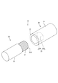
- the perspective view which showed the state after providing the axial recessed part in the single core wire The perspective view which showed the state after inserting and crimping
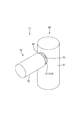
- the perspective view which showed the state after providing the radial direction recessed part in the single core wire Sectional drawing which showed the state which cut
- the wire harness 10 in the present embodiment includes a single core wire 20 and a covered electric wire 30.
- the wire harness 10 is an underfloor harness disposed, for example, under the floor of a vehicle.
- the covered electric wire 30 includes a core wire 31 and an insulating coating 32 made of an insulating resin that covers the core wire 31, and the core wire 31 is a combination of a plurality of metal strands 31A made of a conductive metal. Yes.
- the core wire 31 is illustrated as a single wire for simplification of the drawing, but the core wire 31 includes not only a single wire but also a core wire configured as a stranded wire.
- the single-core wire 20 is configured to include a solid body and a rod-like body portion 21 that extends in the axial direction and a wire fixing portion 22 that constitutes a part of the body portion 21.
- the electric wire fixing portion 22 before the core wire 31 is fixed has a bottomed concave shape as a whole, and has an axial concave portion 23 that opens in the axial direction of the main body portion 21.
- the inner wall of the axial recess 23 includes a peripheral wall 23A that is continuous in the circumferential direction and a back wall 23B that is disposed at the back end of the peripheral wall 23A.
- the term “solid” refers to a member that is used as an opposite word of hollow and is not hollowed out, that is, a member that is clogged inside.
- the core wire 31 is inserted into the axial recess 23 in a state surrounded by the peripheral wall 23A. Then, the peripheral wall 23A is crimped to the core wire 31 by caulking the peripheral wall 23A over, for example, hexagonal caulking. Thereby, the core wire 31 of the covered electric wire 30 is fixed to the electric wire fixing portion 22, and at the same time, the peripheral wall 23A of the electric wire fixing portion 22 and the core wire 31 of the covered electric wire 30 are connected to be conductive. That is, the electric wire fixing portion 22 is formed into a terminal by configuring a part of the single core wire 20 in a concave shape, and can also be referred to as a terminal portion.
- fixed part 22 in this embodiment forms the end part of the single core wire 20 in the columnar shape from the axial direction, it is formed by processing methods other than cutting, for example, press work etc. It may be formed.
- the core wire 31 is being fixed to the electric wire fixing
- the core wire 31 can be surrounded by the inner wall (the peripheral wall 23A) before the core wire 31 is fixed to the electric wire fixing portion 22, a part of the plurality of strands 31A protrudes from the inner wall. It is possible to prevent the wire from being fixed, and to reduce the size of the wire fixing portion. Therefore, it is possible to prevent the protruding wire 31A from coming into contact with another circuit and causing a short circuit between the circuits.
- the electric wire fixing part 22 before the core wire 31 is fixed may have a bottomed concave shape as a whole. According to such a configuration, the core wire 31 can be positioned by inserting the core wire 31 into the inner wall (circumferential wall 23A) and abutting the tip of the core wire 31 against the inner wall (the inner wall 23B). .
- An inner wall is good also as a structure which is an inner wall of the axial direction recessed part 23 which opened the edge part of the main-body part 21 to the axial direction. According to such a configuration, the single core wire 20 and the covered electric wire 30 are arranged side by side in the axial direction of the main body portion 21.
- the wire harness 10 disclosed by this specification is a solid and rod-shaped single core wire 20, the terminal part (electric wire fixing part 22) which comprised some single core wires 20 in concave shape, and several strands It is good also as a structure provided with the covered electric wire 30 which has the core wire 31 comprised combining 31A, and the core wire 31 was connected to the inner wall of a terminal part so that conduction
- the wire harness 11 in the present embodiment includes the single core wire 40 illustrated in FIG. 6 and the same covered electric wire 30 as that in the first embodiment.
- the single core wire 40 in the present embodiment is different from the single core wire 20 in the first embodiment in the opening direction of the recess, and as shown in FIGS. 6 and 7, the end of the main body 41 is opened in the radial direction.
- a radial recess 43 is provided.
- the inner wall of the radial recess 43 includes a circumferential wall 43A that is continuous in the circumferential direction and a back wall 43B that is disposed at the back end of the circumferential wall 43A.
- the core wire 31 is arranged from the side of the main body 41. It can be fixed simply by inserting it into the radial recess 43 and crimping it. If it does in this way, it can comprise in L shape by the straight single core wire 40 and the linear covered electric wire 30, without bending the covered electric wire 30, and the bending space of the covered electric wire 30 becomes unnecessary, Therefore It can contribute to space.
- the single core wire has a round bar shape in the above embodiment, it may be a square bar single core wire.
- the electric wire fixing part which makes bottomed concave shape is illustrated in Embodiment 2, it is good also considering an electric wire fixing part as a through-hole.
Landscapes
- Connections Effected By Soldering, Adhesion, Or Permanent Deformation (AREA)
- Insulated Conductors (AREA)
Abstract
本明細書によって開示される単芯線(20)は、複数の素線(31A)を合わせて構成された芯線(31)が絶縁被覆(32)によって覆われた被覆電線(30)の芯線(31)に接続される単芯線(20)であって、中実でかつ棒状をなし、軸方向に延びる本体部(21)と、本体部(21)の一部を構成し、芯線(31)が固定される前において芯線(31)の外周に配されかつ連続する内壁を有し、芯線(31)が内壁に囲われた状態で固定される電線固定部(22)とを備えた構成とした。
Description
本明細書によって開示される技術は、単芯線およびワイヤハーネスに関する。
従来、丸棒線および撚り線の導体同士を接続する方法として、特開2013-25997号公報(下記特許文献1)に記載のものが知られている。この丸棒線は、平板状の板体に成形された導体を有している。一方、撚り線は、複数本の素線を撚り合わせた導体を有している。丸棒線の導体に撚り線の導体を重ね合わせて超音波接合を行うことにより、これらが超音波接合された接続箇所が形成される。
しかしながら、上記のような超音波による接合方法では、撚り線が上方に引っ張られた場合に、撚り線の導体が丸棒線の導体から引きはがれやすいという問題がある。かといって、一対のバレルによって撚り線の導体を巻き込む圧着では、素線のはみ出しが発生しやすく、はみ出した素線が他回路に接触する等して回路間で短絡するおそれがある。
本明細書によって開示される単芯線は、複数の素線を合わせて構成された芯線が絶縁被覆によって覆われた被覆電線の前記芯線に接続される単芯線であって、中実でかつ棒状をなし、軸方向に延びる本体部と、前記本体部の一部を構成し、前記芯線が固定される前において前記芯線の外周に配されかつ連続する内壁を有し、前記芯線が前記内壁に囲われた状態で固定される電線固定部とを備えた構成とした。
このような構成によると、芯線が電線固定部に固定される前に内壁によって芯線を囲うことができるため、複数の素線の一部が内壁からはみ出して固定されることを防止でき、電線固定部の小型化も図ることができる。したがって、はみ出した素線が他回路に接触する等して回路間で短絡することを防止できる。
本明細書によって開示される単芯線は、以下の構成としてもよい。
前記芯線が固定される前の前記電線固定部は、全体として有底の凹形状をなす構成としてもよい。
このような構成によると、芯線を内壁の内側に挿入し、芯線の先端を内壁の奥端に突き当てることにより、芯線の位置決めを行うことができる。
前記芯線が固定される前の前記電線固定部は、全体として有底の凹形状をなす構成としてもよい。
このような構成によると、芯線を内壁の内側に挿入し、芯線の先端を内壁の奥端に突き当てることにより、芯線の位置決めを行うことができる。
前記内壁は、前記本体部の端部を軸方向に開口させた軸方向凹部の内壁である構成としてもよい。
このような構成によると、単芯線と被覆電線が本体部の軸方向に並んで配置されることになる。
このような構成によると、単芯線と被覆電線が本体部の軸方向に並んで配置されることになる。
前記内壁は、前記本体部の端部を径方向に開口させた径方向凹部の内壁である構成としてもよい。
このような構成によると、例えば被覆電線を単芯線に対して90°曲げて配置する必要がある場合に、被覆電線の曲げスペースが不要になるため、省スペース化に寄与しうる。
このような構成によると、例えば被覆電線を単芯線に対して90°曲げて配置する必要がある場合に、被覆電線の曲げスペースが不要になるため、省スペース化に寄与しうる。
また、本明細書によって開示されるワイヤハーネスは、中実でかつ棒状の単芯線と、前記単芯線の一部を凹状に構成した端子部と、複数の素線を合わせて構成された芯線を有し、前記芯線が前記端子部の内壁に導通可能に接続された被覆電線とを備えた構成としてもよい。
このような構成によると、単芯線の一部を端子部としているため、端子の新設が不要になる。
このような構成によると、単芯線の一部を端子部としているため、端子の新設が不要になる。
本明細書によって開示される単芯線によれば、電線固定部における素線のはみ出しを防ぐことができる。
<実施形態1>
実施形態1を図1から図3の図面を参照しながら説明する。本実施形態におけるワイヤハーネス10は、図3に示すように、単芯線20と、被覆電線30とを備えて構成されている。このワイヤハーネス10は、例えば車両の床下等に配設される床下ハーネスとされている。
実施形態1を図1から図3の図面を参照しながら説明する。本実施形態におけるワイヤハーネス10は、図3に示すように、単芯線20と、被覆電線30とを備えて構成されている。このワイヤハーネス10は、例えば車両の床下等に配設される床下ハーネスとされている。
被覆電線30は、芯線31と、この芯線31を被覆する絶縁樹脂からなる絶縁被覆32とを備え、芯線31は、導電性の金属からなる複数本の金属素線31Aを合わせたものとされている。なお、本実施形態では図面の簡素化のため、単線として芯線31を図示しているが、芯線31は単線のみならず撚り線として構成された芯線も含む。
単芯線20は、図2に示すように、中実でかつ棒状をなし、軸方向に延びる本体部21と、本体部21の一部を構成する電線固定部22とを備えて構成されている。芯線31が固定される前の電線固定部22は、全体として有底の凹形状をなし、本体部21の軸方向に開口する軸方向凹部23を有している。この軸方向凹部23の内壁は、周方向に連続した周壁23Aと、周壁23Aの奥端に配された奥壁23Bとからなる。ここで、中実とは、中空の反対語として使用しており、内部がくりぬかれていない部材、すなわち内部が詰まった部材のことである。
軸方向凹部23の内部には、芯線31が周壁23Aに囲われた状態で挿入されるようになっている。そして、周壁23Aを例えば六角かしめ等によって全周に亘ってかしめることで、周壁23Aが芯線31に圧着される。これにより、被覆電線30の芯線31が電線固定部22に固定されると同時に、電線固定部22の周壁23Aと被覆電線30の芯線31とが導通可能に接続される。すなわち、電線固定部22は、単芯線20の一部を凹状に構成することで端子化としたものであり、端子部ということもできる。
なお、本実施形態における電線固定部22は、単芯線20の端部をその軸方向から円柱状に切削加工を施すことによって形成したものであるが、切削以外の加工方法、例えばプレス加工等によって形成してもよい。また、本実施形態では、圧着によって芯線31を電線固定部22に固定しているが、芯線31の固定方法は圧着に限らず、超音波や抵抗溶接などの溶着方法を用いてもよい。
以上のように本実施形態では、芯線31が電線固定部22に固定される前に内壁(周壁23A)によって芯線31を囲うことができるため、複数の素線31Aの一部が内壁からはみ出して固定されることを防止でき、電線固定部の小型化も図ることができる。したがって、はみ出した素線31Aが他回路に接触する等して回路間で短絡することを防止できる。
芯線31が固定される前の電線固定部22は、全体として有底の凹形状をなす構成としてもよい。
このような構成によると、芯線31を内壁(周壁23A)の内側に挿入し、芯線31の先端を内壁の奥端(奥壁23B)に突き当てることにより、芯線31の位置決めを行うことができる。
このような構成によると、芯線31を内壁(周壁23A)の内側に挿入し、芯線31の先端を内壁の奥端(奥壁23B)に突き当てることにより、芯線31の位置決めを行うことができる。
内壁は、本体部21の端部を軸方向に開口させた軸方向凹部23の内壁である構成としてもよい。
このような構成によると、単芯線20と被覆電線30が本体部21の軸方向に並んで配置されることになる。
このような構成によると、単芯線20と被覆電線30が本体部21の軸方向に並んで配置されることになる。
また、本明細書によって開示されるワイヤハーネス10は、中実でかつ棒状の単芯線20と、単芯線20の一部を凹状に構成した端子部(電線固定部22)と、複数の素線31Aを合わせて構成された芯線31を有し、芯線31が端子部の内壁に導通可能に接続された被覆電線30とを備えた構成としてもよい。
このような構成によると、単芯線20の一部を端子部(電線固定部22)としているため、端子の新設が不要になる。
このような構成によると、単芯線20の一部を端子部(電線固定部22)としているため、端子の新設が不要になる。
<実施形態2>
次に、実施形態2を図4から図8の図面を参照しながら説明する。本実施形態におけるワイヤハーネス11は、図6に示す単芯線40と、実施形態1と同じ被覆電線30とを備えて構成されている。本実施形態における単芯線40は、実施形態1の単芯線20とは凹部の開口方向が異なっており、図6および図7に示すように、本体部41の端部を径方向に開口させた径方向凹部43を有している。この径方向凹部43の内壁は、周方向に連続した周壁43Aと、周壁43Aの奥端に配された奥壁43Bとからなる。
次に、実施形態2を図4から図8の図面を参照しながら説明する。本実施形態におけるワイヤハーネス11は、図6に示す単芯線40と、実施形態1と同じ被覆電線30とを備えて構成されている。本実施形態における単芯線40は、実施形態1の単芯線20とは凹部の開口方向が異なっており、図6および図7に示すように、本体部41の端部を径方向に開口させた径方向凹部43を有している。この径方向凹部43の内壁は、周方向に連続した周壁43Aと、周壁43Aの奥端に配された奥壁43Bとからなる。
このような構成によると、図4および図5に示すように、例えば被覆電線30を単芯線40に対して90°曲げて配置する必要がある場合に、芯線31を本体部41の側方から径方向凹部43の内部に挿入してかしめて圧着するだけで固定することができる。このようにすると、被覆電線30を曲げることなく、直線状の単芯線40と直線状の被覆電線30とによってL字形に構成することができ、被覆電線30の曲げスペースが不要になるため、省スペース化に寄与しうる。
<他の実施形態>
本明細書によって開示される技術は上記記述及び図面によって説明した実施形態に限定されるものではなく、例えば次のような種々の態様も含まれる。
(1)上記実施形態では単芯線を丸棒状としているものの、角棒状の単芯線としてもよい。
(2)実施形態2では有底の凹形状をなす電線固定部を例示しているものの、電線固定部を貫通孔としてもよい。
本明細書によって開示される技術は上記記述及び図面によって説明した実施形態に限定されるものではなく、例えば次のような種々の態様も含まれる。
(1)上記実施形態では単芯線を丸棒状としているものの、角棒状の単芯線としてもよい。
(2)実施形態2では有底の凹形状をなす電線固定部を例示しているものの、電線固定部を貫通孔としてもよい。
10、11…ワイヤハーネス
20、40…単芯線
21、41…本体部
22、42…電線固定部(端子部)
23…軸方向凹部
23A…周壁(内壁)
23B…奥壁(内壁)
30…被覆電線
31…芯線
31A…素線
32…絶縁被覆
43…径方向凹部
43A…周壁
43B…奥壁
20、40…単芯線
21、41…本体部
22、42…電線固定部(端子部)
23…軸方向凹部
23A…周壁(内壁)
23B…奥壁(内壁)
30…被覆電線
31…芯線
31A…素線
32…絶縁被覆
43…径方向凹部
43A…周壁
43B…奥壁
Claims (5)
- 複数の素線を合わせて構成された芯線が絶縁被覆によって覆われた被覆電線の前記芯線に接続される単芯線であって、
中実でかつ棒状をなし、軸方向に延びる本体部と、
前記本体部の一部を構成し、前記芯線が固定される前において前記芯線の外周に配されかつ連続する内壁を有し、前記芯線が前記内壁に囲われた状態で固定される電線固定部とを備えた単芯線。 - 前記芯線が固定される前の前記電線固定部は、全体として有底の凹形状をなす請求項1に記載の単芯線。
- 前記内壁は、前記本体部の端部を軸方向に開口させた軸方向凹部の内壁である請求項2に記載の単芯線。
- 前記内壁は、前記本体部の端部を径方向に開口させた径方向凹部の内壁である請求項2に記載の単芯線。
- 中実でかつ棒状の単芯線と、
前記単芯線の一部を凹状に構成した端子部と、
複数の素線を合わせて構成された芯線を有し、前記芯線が前記端子部の内壁に導通可能に接続された被覆電線とを備えたワイヤハーネス。
Priority Applications (2)
| Application Number | Priority Date | Filing Date | Title |
|---|---|---|---|
| CN201680021509.1A CN107431279A (zh) | 2015-04-17 | 2016-03-28 | 单芯线以及电线束 |
| US15/564,228 US20180131167A1 (en) | 2015-04-17 | 2016-03-28 | Single-core wire and wire harness |
Applications Claiming Priority (2)
| Application Number | Priority Date | Filing Date | Title |
|---|---|---|---|
| JP2015084969A JP2016207335A (ja) | 2015-04-17 | 2015-04-17 | 単芯線およびワイヤハーネス |
| JP2015-084969 | 2015-04-17 |
Publications (1)
| Publication Number | Publication Date |
|---|---|
| WO2016167107A1 true WO2016167107A1 (ja) | 2016-10-20 |
Family
ID=57126726
Family Applications (1)
| Application Number | Title | Priority Date | Filing Date |
|---|---|---|---|
| PCT/JP2016/059822 Ceased WO2016167107A1 (ja) | 2015-04-17 | 2016-03-28 | 単芯線およびワイヤハーネス |
Country Status (4)
| Country | Link |
|---|---|
| US (1) | US20180131167A1 (ja) |
| JP (1) | JP2016207335A (ja) |
| CN (1) | CN107431279A (ja) |
| WO (1) | WO2016167107A1 (ja) |
Cited By (3)
| Publication number | Priority date | Publication date | Assignee | Title |
|---|---|---|---|---|
| JP2018078060A (ja) * | 2016-11-11 | 2018-05-17 | 住友電装株式会社 | 電線の接合構造及びワイヤハーネス |
| WO2019004214A1 (ja) * | 2017-06-29 | 2019-01-03 | 住友電装株式会社 | 導電路及びワイヤハーネス |
| WO2021182113A1 (ja) * | 2020-03-10 | 2021-09-16 | 住友電装株式会社 | ワイヤハーネス |
Citations (5)
| Publication number | Priority date | Publication date | Assignee | Title |
|---|---|---|---|---|
| JPS54146381U (ja) * | 1978-04-03 | 1979-10-11 | ||
| JPH06275325A (ja) * | 1993-03-24 | 1994-09-30 | Mitsubishi Electric Home Appliance Co Ltd | 導電線の接続構造 |
| JPH0817487A (ja) * | 1994-06-30 | 1996-01-19 | Toshiba Corp | 超電導線の接続方法 |
| JP2010198978A (ja) * | 2009-02-26 | 2010-09-09 | Hitachi Cable Ltd | 導体接続構造 |
| JP2013025997A (ja) * | 2011-07-20 | 2013-02-04 | Yazaki Corp | 電線の接続方法 |
Family Cites Families (7)
| Publication number | Priority date | Publication date | Assignee | Title |
|---|---|---|---|---|
| US4247382A (en) * | 1979-07-18 | 1981-01-27 | Smith Noel E | Cathode assembly for electro-chemical apparatus |
| EP0619443B1 (de) * | 1993-04-20 | 1994-10-26 | Brugg Drahtseil AG | Anschlussstück an einem Drahtseilende |
| JP2002216864A (ja) * | 2001-01-19 | 2002-08-02 | Yazaki Corp | 電線の接続構造及び接続方法 |
| FR2917244B1 (fr) * | 2007-06-06 | 2012-12-21 | Peugeot Citroen Automobiles Sa | Cosse de connexion. |
| US7690936B1 (en) * | 2009-02-25 | 2010-04-06 | Octio Geophysical As | Subsea electrical penetrator |
| JP5904355B2 (ja) * | 2011-08-02 | 2016-04-13 | 矢崎総業株式会社 | 単芯電線の端子圧着構造 |
| JP2013246886A (ja) * | 2012-05-23 | 2013-12-09 | Auto Network Gijutsu Kenkyusho:Kk | 端子付き電線およびその製造方法、ならびに治具 |
-
2015
- 2015-04-17 JP JP2015084969A patent/JP2016207335A/ja active Pending
-
2016
- 2016-03-28 US US15/564,228 patent/US20180131167A1/en not_active Abandoned
- 2016-03-28 CN CN201680021509.1A patent/CN107431279A/zh active Pending
- 2016-03-28 WO PCT/JP2016/059822 patent/WO2016167107A1/ja not_active Ceased
Patent Citations (5)
| Publication number | Priority date | Publication date | Assignee | Title |
|---|---|---|---|---|
| JPS54146381U (ja) * | 1978-04-03 | 1979-10-11 | ||
| JPH06275325A (ja) * | 1993-03-24 | 1994-09-30 | Mitsubishi Electric Home Appliance Co Ltd | 導電線の接続構造 |
| JPH0817487A (ja) * | 1994-06-30 | 1996-01-19 | Toshiba Corp | 超電導線の接続方法 |
| JP2010198978A (ja) * | 2009-02-26 | 2010-09-09 | Hitachi Cable Ltd | 導体接続構造 |
| JP2013025997A (ja) * | 2011-07-20 | 2013-02-04 | Yazaki Corp | 電線の接続方法 |
Cited By (6)
| Publication number | Priority date | Publication date | Assignee | Title |
|---|---|---|---|---|
| JP2018078060A (ja) * | 2016-11-11 | 2018-05-17 | 住友電装株式会社 | 電線の接合構造及びワイヤハーネス |
| CN108075242A (zh) * | 2016-11-11 | 2018-05-25 | 住友电装株式会社 | 电线的接合结构以及电线束 |
| CN108075242B (zh) * | 2016-11-11 | 2020-07-17 | 住友电装株式会社 | 电线的接合结构以及电线束 |
| WO2019004214A1 (ja) * | 2017-06-29 | 2019-01-03 | 住友電装株式会社 | 導電路及びワイヤハーネス |
| US10937567B2 (en) | 2017-06-29 | 2021-03-02 | Sumitomo Wiring Systems, Ltd. | Conduction path and wire harness |
| WO2021182113A1 (ja) * | 2020-03-10 | 2021-09-16 | 住友電装株式会社 | ワイヤハーネス |
Also Published As
| Publication number | Publication date |
|---|---|
| JP2016207335A (ja) | 2016-12-08 |
| CN107431279A (zh) | 2017-12-01 |
| US20180131167A1 (en) | 2018-05-10 |
Similar Documents
| Publication | Publication Date | Title |
|---|---|---|
| JP5945155B2 (ja) | 電線の外部導体端子の接続構造 | |
| JP6281448B2 (ja) | 導電路 | |
| JP6607405B2 (ja) | 導電路 | |
| JP6471909B2 (ja) | ワイヤハーネス | |
| JP5690538B2 (ja) | 繊維導体の接続構造 | |
| WO2016167107A1 (ja) | 単芯線およびワイヤハーネス | |
| CN115298766B (zh) | 线束 | |
| KR102513547B1 (ko) | 코일단말의 접속구조 | |
| JP6471910B2 (ja) | ワイヤハーネス | |
| JP6409672B2 (ja) | 電線モジュール | |
| JP6158539B2 (ja) | 電線の分岐構造 | |
| US10630003B2 (en) | Conductor connecting structure and wire harness | |
| WO2017187954A1 (ja) | 導電部材 | |
| JP4503458B2 (ja) | シールド電線のアース接続具およびアース接続方法 | |
| JP2019012598A (ja) | 導電路及びワイヤハーネス | |
| JP2014089913A (ja) | 保護カバー | |
| JP6068222B2 (ja) | ノイズ低減構造 | |
| JP6514555B2 (ja) | 中継端子、及び、ワイヤハーネス | |
| JP6556512B2 (ja) | ワイヤハーネス | |
| JP6225074B2 (ja) | 端子付き電線及びその製造方法 | |
| JP2012038673A (ja) | ワイヤハーネス | |
| JP7107186B2 (ja) | リード線と端子台の接続構造 | |
| JP2017107730A (ja) | アース端子、及び、ワイヤハーネス | |
| JP5213645B2 (ja) | アース処理端子上でのケーブル接続構造 | |
| JP2020053252A (ja) | 端子付電線及びその製造方法 |
Legal Events
| Date | Code | Title | Description |
|---|---|---|---|
| 121 | Ep: the epo has been informed by wipo that ep was designated in this application |
Ref document number: 16779898 Country of ref document: EP Kind code of ref document: A1 |
|
| DPE1 | Request for preliminary examination filed after expiration of 19th month from priority date (pct application filed from 20040101) | ||
| WWE | Wipo information: entry into national phase |
Ref document number: 15564228 Country of ref document: US |
|
| NENP | Non-entry into the national phase |
Ref country code: DE |
|
| 122 | Ep: pct application non-entry in european phase |
Ref document number: 16779898 Country of ref document: EP Kind code of ref document: A1 |