WO2016167092A1 - ガラス基板梱包体 - Google Patents
ガラス基板梱包体 Download PDFInfo
- Publication number
- WO2016167092A1 WO2016167092A1 PCT/JP2016/059216 JP2016059216W WO2016167092A1 WO 2016167092 A1 WO2016167092 A1 WO 2016167092A1 JP 2016059216 W JP2016059216 W JP 2016059216W WO 2016167092 A1 WO2016167092 A1 WO 2016167092A1
- Authority
- WO
- WIPO (PCT)
- Prior art keywords
- glass substrate
- shaped glass
- disk
- shaped
- disc
- Prior art date
- Legal status (The legal status is an assumption and is not a legal conclusion. Google has not performed a legal analysis and makes no representation as to the accuracy of the status listed.)
- Ceased
Links
Images

Classifications
-
- H—ELECTRICITY
- H10—SEMICONDUCTOR DEVICES; ELECTRIC SOLID-STATE DEVICES NOT OTHERWISE PROVIDED FOR
- H10P—GENERIC PROCESSES OR APPARATUS FOR THE MANUFACTURE OR TREATMENT OF DEVICES COVERED BY CLASS H10
- H10P72/00—Handling or holding of wafers, substrates or devices during manufacture or treatment thereof
- H10P72/10—Handling or holding of wafers, substrates or devices during manufacture or treatment thereof using carriers specially adapted therefor, e.g. front opening unified pods [FOUP]
- H10P72/19—Handling or holding of wafers, substrates or devices during manufacture or treatment thereof using carriers specially adapted therefor, e.g. front opening unified pods [FOUP] closed carriers
- H10P72/1908—Handling or holding of wafers, substrates or devices during manufacture or treatment thereof using carriers specially adapted therefor, e.g. front opening unified pods [FOUP] closed carriers specially adapted for containing substrates other than wafers
-
- B—PERFORMING OPERATIONS; TRANSPORTING
- B65—CONVEYING; PACKING; STORING; HANDLING THIN OR FILAMENTARY MATERIAL
- B65D—CONTAINERS FOR STORAGE OR TRANSPORT OF ARTICLES OR MATERIALS, e.g. BAGS, BARRELS, BOTTLES, BOXES, CANS, CARTONS, CRATES, DRUMS, JARS, TANKS, HOPPERS, FORWARDING CONTAINERS; ACCESSORIES, CLOSURES, OR FITTINGS THEREFOR; PACKAGING ELEMENTS; PACKAGES
- B65D85/00—Containers, packaging elements or packages, specially adapted for particular articles or materials
- B65D85/30—Containers, packaging elements or packages, specially adapted for particular articles or materials for articles particularly sensitive to damage by shock or pressure
- B65D85/48—Containers, packaging elements or packages, specially adapted for particular articles or materials for articles particularly sensitive to damage by shock or pressure for glass sheets
-
- B—PERFORMING OPERATIONS; TRANSPORTING
- B65—CONVEYING; PACKING; STORING; HANDLING THIN OR FILAMENTARY MATERIAL
- B65D—CONTAINERS FOR STORAGE OR TRANSPORT OF ARTICLES OR MATERIALS, e.g. BAGS, BARRELS, BOTTLES, BOXES, CANS, CARTONS, CRATES, DRUMS, JARS, TANKS, HOPPERS, FORWARDING CONTAINERS; ACCESSORIES, CLOSURES, OR FITTINGS THEREFOR; PACKAGING ELEMENTS; PACKAGES
- B65D81/00—Containers, packaging elements, or packages, for contents presenting particular transport or storage problems, or adapted to be used for non-packaging purposes after removal of contents
- B65D81/02—Containers, packaging elements, or packages, for contents presenting particular transport or storage problems, or adapted to be used for non-packaging purposes after removal of contents specially adapted to protect contents from mechanical damage
- B65D81/05—Containers, packaging elements, or packages, for contents presenting particular transport or storage problems, or adapted to be used for non-packaging purposes after removal of contents specially adapted to protect contents from mechanical damage maintaining contents at spaced relation from package walls, or from other contents
-
- B—PERFORMING OPERATIONS; TRANSPORTING
- B65—CONVEYING; PACKING; STORING; HANDLING THIN OR FILAMENTARY MATERIAL
- B65D—CONTAINERS FOR STORAGE OR TRANSPORT OF ARTICLES OR MATERIALS, e.g. BAGS, BARRELS, BOTTLES, BOXES, CANS, CARTONS, CRATES, DRUMS, JARS, TANKS, HOPPERS, FORWARDING CONTAINERS; ACCESSORIES, CLOSURES, OR FITTINGS THEREFOR; PACKAGING ELEMENTS; PACKAGES
- B65D81/00—Containers, packaging elements, or packages, for contents presenting particular transport or storage problems, or adapted to be used for non-packaging purposes after removal of contents
- B65D81/02—Containers, packaging elements, or packages, for contents presenting particular transport or storage problems, or adapted to be used for non-packaging purposes after removal of contents specially adapted to protect contents from mechanical damage
- B65D81/05—Containers, packaging elements, or packages, for contents presenting particular transport or storage problems, or adapted to be used for non-packaging purposes after removal of contents specially adapted to protect contents from mechanical damage maintaining contents at spaced relation from package walls, or from other contents
- B65D81/051—Containers, packaging elements, or packages, for contents presenting particular transport or storage problems, or adapted to be used for non-packaging purposes after removal of contents specially adapted to protect contents from mechanical damage maintaining contents at spaced relation from package walls, or from other contents using pillow-like elements filled with cushioning material, e.g. elastic foam, fabric
-
- B—PERFORMING OPERATIONS; TRANSPORTING
- B65—CONVEYING; PACKING; STORING; HANDLING THIN OR FILAMENTARY MATERIAL
- B65D—CONTAINERS FOR STORAGE OR TRANSPORT OF ARTICLES OR MATERIALS, e.g. BAGS, BARRELS, BOTTLES, BOXES, CANS, CARTONS, CRATES, DRUMS, JARS, TANKS, HOPPERS, FORWARDING CONTAINERS; ACCESSORIES, CLOSURES, OR FITTINGS THEREFOR; PACKAGING ELEMENTS; PACKAGES
- B65D85/00—Containers, packaging elements or packages, specially adapted for particular articles or materials
- B65D85/62—Containers, packaging elements or packages, specially adapted for particular articles or materials for stacks of articles; for special arrangements of groups of articles
-
- H—ELECTRICITY
- H10—SEMICONDUCTOR DEVICES; ELECTRIC SOLID-STATE DEVICES NOT OTHERWISE PROVIDED FOR
- H10P—GENERIC PROCESSES OR APPARATUS FOR THE MANUFACTURE OR TREATMENT OF DEVICES COVERED BY CLASS H10
- H10P14/00—Formation of materials, e.g. in the shape of layers or pillars
- H10P14/20—Formation of materials, e.g. in the shape of layers or pillars of semiconductor materials
- H10P14/29—Formation of materials, e.g. in the shape of layers or pillars of semiconductor materials characterised by the substrates
- H10P14/2901—Materials
- H10P14/2922—Materials being non-crystalline insulating materials, e.g. glass or polymers
-
- H—ELECTRICITY
- H10—SEMICONDUCTOR DEVICES; ELECTRIC SOLID-STATE DEVICES NOT OTHERWISE PROVIDED FOR
- H10P—GENERIC PROCESSES OR APPARATUS FOR THE MANUFACTURE OR TREATMENT OF DEVICES COVERED BY CLASS H10
- H10P72/00—Handling or holding of wafers, substrates or devices during manufacture or treatment thereof
- H10P72/10—Handling or holding of wafers, substrates or devices during manufacture or treatment thereof using carriers specially adapted therefor, e.g. front opening unified pods [FOUP]
- H10P72/19—Handling or holding of wafers, substrates or devices during manufacture or treatment thereof using carriers specially adapted therefor, e.g. front opening unified pods [FOUP] closed carriers
- H10P72/1911—Handling or holding of wafers, substrates or devices during manufacture or treatment thereof using carriers specially adapted therefor, e.g. front opening unified pods [FOUP] closed carriers characterised by materials, roughness, coatings or the like
- H10P72/1912—Handling or holding of wafers, substrates or devices during manufacture or treatment thereof using carriers specially adapted therefor, e.g. front opening unified pods [FOUP] closed carriers characterised by materials, roughness, coatings or the like characterised by shock absorbing elements, e.g. retainers or cushions
Definitions
- the present invention relates to a glass substrate package in which a plurality of glass substrates are packaged in a packing material, and more particularly to a package in which a disk-shaped glass substrate is packed.
- Patent Document 1 discloses a package including a substrate container that can accommodate a plurality of disk-shaped glass substrates in a vertical orientation in parallel.
- the substrate storage container is composed of a storage portion for vertically storing a plurality of disc-shaped glass substrates, and a lid portion attached to the storage portion. Are formed with a plurality of holding guides for accommodating a plurality of disc-shaped glass substrates at predetermined intervals.
- the lid is formed with a plurality of holes for inserting each disk-shaped glass substrate into the housing.
- the package disclosed in Patent Document 1 has the following problems to be solved. That is, in the package, it is necessary that the number of holding guides and holes corresponding to the number of disc-shaped glass substrates to be accommodated be formed in the substrate accommodating container (accommodating portion, lid portion). Therefore, as the number of disc-shaped glass substrates to be accommodated increases, the number of holding guides and holes to be formed in the substrate accommodating container inevitably increases, and the manufacturing cost of the substrate accommodating container increases. As a result, there is a difficulty that the cost required for packaging increases.
- the portion located at the lower end of the outer peripheral end of the disk-shaped glass substrate placed vertically is the storage section. Excessive stress acts locally on the part in a point contact state.
- the outer peripheral edge part of a disk shaped glass substrate is chamfered with a grinding tool or the like. For this reason, the disc-shaped glass substrate may be damaged starting from the outer peripheral end due to the action of stress on cracks or the like generated during processing.
- the present invention made in view of the above circumstances has a technical problem to enable packaging of a plurality of disc-shaped glass substrates at a low cost while preventing damage to the disc-shaped glass substrate.
- the present invention devised to solve the above problems is a glass substrate package in which a plurality of disc-shaped glass substrates are packed in a packing material, and a protective sheet is provided between the plurality of disc-shaped glass substrates. It is characterized in that a plurality of disc-shaped glass substrates are stacked in a flat state and packed in an intervening state.
- a plurality of disk-shaped glass substrates are stacked in a flat position, and a plurality of disk-shaped glass substrates are packed with a packing material only by interposing a protective sheet therebetween. Can do. Therefore, it is possible to suppress the cost required for packing these disk-shaped glass substrates. Furthermore, since a plurality of disk-shaped glass substrates are stacked in a flat position, it is possible to avoid an excessive stress from acting on the outer peripheral edge of each disk-shaped glass substrate. As a result, it is possible to accurately prevent the occurrence of a situation in which the disc-shaped glass substrate is damaged starting from the outer peripheral end. As described above, according to the glass substrate package of the present invention, it is possible to pack a plurality of disc-shaped glass substrates at low cost while preventing the disc-shaped glass substrate from being damaged.
- the disk-shaped glass substrate may have a positioning portion obtained by removing a part of the outer peripheral end portion in order to position the disk-shaped glass substrate.
- the glass substrate package according to the present invention As described above, it is possible to accurately prevent the damage of each disk-shaped glass substrate due to the fact that a plurality of disk-shaped glass substrates are stacked flat. Is possible. Therefore, when packing a disk-shaped glass substrate having a positioning portion, if the glass substrate packing body according to the present invention is adopted, its usefulness can be further enhanced.
- a plurality of disc-shaped glass substrates are laminated in a state where the positions of the positioning portions are aligned with each other.
- a packing material has a side wall part surrounding the outer peripheral edge part of a disk shaped glass substrate, and the disk shaped glass substrate is packed so that a positioning part may become non-contact with a side wall part.
- each disk-shaped glass substrate moves within the packing material due to vibrations generated in the package, or a plurality of disk-shaped packages. It becomes easy to prevent the occurrence of a situation in which positional deviation occurs between the glass substrates.
- the side wall portion forms a square that circumscribes the disk-shaped glass substrate.
- the packing material has an upper wall portion facing the disk-shaped glass substrate positioned in the uppermost layer among the plurality of disk-shaped glass substrates, and the disk-shaped glass substrate and upper wall positioned in the uppermost layer It is preferable that a cushioning material is filled between the portions.
- the packing material is a box-like body, and the box-like body is configured to be deployable.
- each disk-shaped glass substrate can be easily accommodated in the box-shaped body, and each disk-shaped glass substrate can be easily taken out from the box-shaped body when unpacking.
- the disk-shaped glass substrate has a warp, and a plurality of disk-shaped glass substrates are laminated in a state where the directions of the warp are aligned with each other.
- the disc-shaped glass substrate is provided with a marking for determining the direction of warpage.
- the present invention it is possible to pack a plurality of disc-shaped glass substrates at a low cost while preventing damage to the disc-shaped glass substrate.
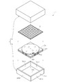
- a glass substrate package 1 is formed by packing a plurality of disc-shaped glass substrates 2 in a box 3 as a packing material (box-shaped body). It is.
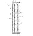
- a plurality of disk-shaped glass substrates 2 are stacked in a flat state and packaged with a slip sheet 4 as a protective sheet interposed between the plurality of disk-shaped glass substrates 2.
- a slip sheet 4 as a protective sheet interposed between the plurality of disk-shaped glass substrates 2.
- Each of the plurality of disk-shaped glass substrates 2 is a glass substrate that serves as a support for supporting the semiconductor wafer in the back grinding process of the semiconductor wafer.
- Each disk-shaped glass substrate 2 is provided with a notch 2aa as a positioning portion formed by removing a part of the outer peripheral end 2a. This notch 2aa is formed in order to determine the orientation of the disk-shaped glass substrate 2 in a plan view and perform positioning.
- Each disk-shaped glass substrate 2 has a curved curvature so that one of its upper and lower surfaces is convex, and the vicinity of the notch 2aa in each disk-shaped glass substrate 2 is based on the SEMI standard. Marking 2b for discriminating the direction of warpage is applied.
- the marking 2b is, for example, a character string drawn by a large number of dots formed on the disk-shaped glass substrate 2 by laser irradiation.
- the plurality of disk-shaped glass substrates 2 are laminated in a state where the positions of the notches 2aa and the warping directions are aligned with each other.
- a plurality of disk-shaped glass substrates 2 are laminated in a state where the lower surfaces of the disk-shaped glass substrates 2 are aligned so that the lower surfaces are convex.
- the average thermal expansion coefficient in the temperature range of 30 ° C. to 380 ° C. of the disk-shaped glass substrate 2 has a small proportion of semiconductor chips in the semiconductor wafer supported by the disk-shaped glass substrate 2, and the sealing material
- the ratio is large, it is preferable to increase, and conversely, when the ratio of the semiconductor chip is large in the semiconductor substrate and the ratio of the sealing material is small, it is preferable to decrease.
- the disc-shaped glass substrate 2 Is a glass composition in terms of mass%, SiO 2 : 55 to 75%, Al 2 O 3 : 15 to 30%, Li 2 O: 0.1 to 6%, Na 2 O + K 2 O (Na 2 O and K the total amount of 2 O): 0 ⁇ 8% , MgO + CaO + SrO + BaO (MgO, CaO, SrO and BaO in total amount): a preferably contains 0-10%, or, SiO 2: 55 ⁇ 75% , Al 2 O 3 : 10 to 30%, Li 2 O + Na 2 O + K 2 O (total amount of Li 2 O, Na 2 O and K 2 O): 0 to 0.3%, MgO + CaO
- the disc-shaped glass substrate 2 Is a glass composition in mass%, SiO 2 : 55 to 75%, Al 2 O 3 : 3 to 15%, B 2 O 3 : 5 to 20%, MgO: 0 to 5%, CaO: 0 to 10 %, SrO: 0-5%, BaO: 0-5%, ZnO: 0-5%, Na 2 O: 5-15%, K 2 O: 0-10%, SiO 2 : 64 to 71%, Al 2 O 3 : 5 to 10%, B 2 O 3 : 8 to 15%, MgO: 0 to 5%, CaO: 0 to 6%, SrO: 0 to 3%, BaO: 0 to 3%, ZnO: 0 ⁇ 3 %
- the average thermal expansion coefficient of the disc-shaped glass substrate 2 in the temperature range of 30 ° C. to 380 ° C. to 70 ⁇ 10 ⁇ 7 / ° C. or more and 85 ⁇ 10 ⁇ 7 / ° C.
- the disc-shaped glass substrate 2 Has a glass composition of mass%, SiO 2 : 60 to 75%, Al 2 O 3 : 5 to 15%, B 2 O 3 : 5 to 20%, MgO: 0 to 5%, CaO: 0 to 10 %, SrO: 0-5%, BaO: 0-5%, ZnO: 0-5%, Na 2 O: 7-16%, K 2 O: 0-8%, SiO 2 : 60 to 68%, Al 2 O 3 : 5 to 15%, B 2 O 3 : 5 to 20%, MgO: 0 to 5%, CaO: 0 to 10%, SrO: 0 to 3%, BaO: 0 to 3%, ZnO: 0 ⁇ 3 %, Na 2 O: 8 ⁇ 16%, K 2 O: 0 favored more to contain ⁇ 3% There.
- the disc-shaped glass substrate 2 is a glass composition in mass%, SiO 2 : 55 to 70%, Al 2 O 3 : 3 to 13%, B 2 O 3 : 2 to 8%, MgO: 0 to 5%, CaO: 0 to It is preferable to contain 10%, SrO: 0 to 5%, BaO: 0 to 5%, ZnO: 0 to 5%, Na 2 O: 10 to 21%, K 2 O: 0 to 5%.
- the average coefficient of thermal expansion of the disk-shaped glass substrate 2 in the temperature range of 30 ° C. to 380 ° C. is to be controlled to be over 120 ⁇ 10 ⁇ 7 / ° C. and 165 ⁇ 10 ⁇ 7 / ° C.
- the disk-shaped glass substrate 2 Has a glass composition of mass%, SiO 2 : 53 to 65%, Al 2 O 3 : 3 to 13%, B 2 O 3 : 0 to 5%, MgO: 0.1 to 6%, CaO: 0 ⁇ 10%, SrO: 0-5%, BaO: 0-5%, ZnO: 0-5%, Na 2 O + K 2 O: 20-40%, Na 2 O: 12-21%, K 2 O: 7 It preferably contains ⁇ 21%.
- the disk-shaped glass substrate 2 with small variation in plate thickness is obtained. It becomes easy.
- the interleaf paper 4 is made of, for example, a pulp sheet or a polyethylene sheet.
- the interleaf paper 4 is formed in a square shape, and the length of one side of the square is equal to the diameter of the disk-shaped glass substrate 2.
- the interleaving paper 4 can cover the entire main surface (upper surface, lower surface) of the disc-shaped glass substrate 2 and protect the main surface from the occurrence of scratches.
- the corner part (part corresponding to a square corner) of the interleaf paper 4 is in a state of protruding from the outer peripheral end part 2 a of the disk-shaped glass substrate 2.
- the slip sheet 4 is used as the protective sheet, but the present invention is not limited to this, and for example, a resin sheet, a film, or the like may be used as the protective sheet.
- a resin sheet, a film, or the like may be used as the protective sheet.
- the shape of the slip sheet 4 is formed in the square, it is not restricted to this, The slip sheet 4 formed in arbitrary shapes may be used.
- the interleaving paper 4 does not necessarily have to protrude from the outer peripheral end 2a of the disk-shaped glass substrate 2.
- a circular slip sheet 4 having the same area as the main surface of the disc-shaped glass substrate 2 may be used so that the outer contour of the disc-shaped glass substrate 2 and the outer contour of the slip sheet 4 overlap in plan view. .
- the box 3 includes a box body 3a that houses a plurality of disk-shaped glass substrates 2 therein, and a lid 3b that covers the box body 3a from above.
- a material of the box body 3a and the lid 3b resin, wood, paper, plastic, or the like can be used. Both the box body 3 a and the lid 3 b can be fixed via the adhesive tape 5.
- the box body 3a has a bottom 3aa on which a plurality of disk-shaped glass substrates 2 are placed, and a side wall 3ab that is connected to the bottom 3aa and surrounds the outer peripheral end 2a of each disk-shaped glass substrate 2. ing.
- the bottom 3aa is formed in a square shape in plan view.
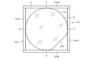
- the side wall portion 3ab has a square shape that circumscribes the disk-shaped glass substrate 2 when the disk-shaped glass substrate 2 is viewed in plan. Thereby, a part of outer peripheral end 2a of each disk-shaped glass substrate 2 and the side wall 3ab are in contact with each other.
- the outer peripheral end 2a of the disk-shaped glass substrate 2 and the side wall 3ab are in contact with each other at four points P, and these four points P are in the circumferential direction of the disk-shaped glass substrate 2. Are located at regular intervals.
- Each disk-shaped glass substrate 2 is accommodated (packed) in the box body 3a so that the notch 2aa in the substrate is not in contact with the side wall 3ab. More specifically, each disk-shaped glass substrate 2 is accommodated (packed) in the box body 3a so that the notch 2aa in each disk-shaped glass substrate 2 is arranged facing a square corner formed by the side wall 3ab. .
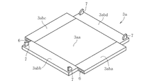
- the side wall 3ab of the box body 3a is composed of four wall portions 3aba to 3abd, and each of the wall portions 3aba to 3abd has its posture from the vertical placement posture shown in FIG. 1 to the flat placement posture shown in FIG. It is possible to change.
- the four wall portions 3aba to 3abd are placed in a flat position, and the box body It is possible to perform the storing operation and the taking-out operation in a state where 3a is expanded.
- holes 6 are formed at both ends in the longitudinal direction of the wall portion 3aba and the wall portion 3abc.
- the wall 3abb and the wall 3abd are formed with projections 7 at both ends in the longitudinal direction. Then, each of the wall portions 3aba to 3abd is placed in a vertical posture, and the projection 7 formed on the wall portion 3abb and the wall portion 3abd is inserted into the hole 6 formed on the wall portion 3aba and the wall portion 3abc, thereby The box body 3a shown in Fig. 1 can be assembled.
- the inner wall surface facing the outer peripheral end portion 2a of the disc-shaped glass substrate 2 is made of a cushioning material (for example, polystyrene foam).
- the lid 3b has an upper wall portion 3ba facing the disc-shaped glass substrate 2 located in the uppermost layer of the plurality of disc-shaped glass substrates 2.
- a bubble cushioning material 8 serving as a cushioning material is filled between the upper wall 3ba of the lid 3b and the disk-shaped glass substrate 2 located in the uppermost layer.
- the cushioning material is not limited to the bubble cushioning material 8, and resin, paper, polystyrene foam, or the like may be used.
- both the box main body 3a and the lid 3b are fixed via the adhesive tape 5.
- the present invention is not limited to this, and both the box main body 3a and the lid 3b are bound with a string.
- a rubber band may be wound around the two to fix it.
- all the four wall portions 3aba to 3abd constituting the side wall portion 3ab of the box body 3a can change the posture from the vertical posture to the flat posture. It is not limited to. The posture may be changed only for a part of the four wall portions 3aba to 3abd.
- a plurality of disk-shaped glass substrates 2 are laminated in a flat position, and a plurality of disk-shaped glass substrates 2 are formed by simply interposing a slip sheet 4 between them. It can be packed by the box 3. Therefore, it is possible to suppress the cost required for packing these disk-shaped glass substrates 2. Furthermore, since a plurality of disk-shaped glass substrates 2 are stacked in a flat manner, it is possible to avoid excessive stress from acting on the outer peripheral end 2a of each disk-shaped glass substrate 2. As a result, it is possible to accurately prevent the occurrence of a situation in which the disc-shaped glass substrate 2 is damaged starting from the outer peripheral end 2a.
- the glass substrate package according to the present invention is not limited to the configuration described in the above embodiment.
- the bottom of the box body is formed in a square shape in plan view, but may be formed in a circular shape or a polygonal shape.
- the side wall portion when the side wall portion is a plan view of the disk-shaped glass substrate, it forms a square that circumscribes the disk-shaped glass substrate. However, it may be circular or polygonal. .
- a protective tape may be attached so as to cover the notch in the glass substrate package according to the above embodiment.
- the protective tape may be individually attached to the notches in each of the plurality of disc-shaped glass substrates, or the notches in each of the plurality of disc-shaped glass substrates may be collectively covered with a single protective tape. May be.
- a circular paper having the same area as the main surface of the disk-shaped glass substrate is used as a slip sheet interposed between the plurality of disk-shaped glass substrates. It is preferable to use paper.
- the disk-shaped glass substrate on which the notch as the positioning portion is formed is packed, but this is not restrictive. As shown in FIG. 5, it is good also as a structure which packed the disk shaped glass substrate 2 in which orientation flat 2ab as a positioning part was formed.
- the disc-shaped glass substrate 2 is preferably accommodated (packed) in the box body 3a so that the orientation flat 2ab on the substrate is not in contact with the side wall 3ab.
- a box is used as a packing material for packing a plurality of disk-shaped glass substrates, but this is not restrictive.
- a bag, wrapping paper, or the like may be used as the packaging material.
Landscapes
- Engineering & Computer Science (AREA)
- Mechanical Engineering (AREA)
- Packaging Frangible Articles (AREA)
- Wrapping Of Specific Fragile Articles (AREA)
Abstract
Description
2 円盤状ガラス基板
2a 外周端部
2aa ノッチ
2ab オリエンテーションフラット
2b マーキング
3 箱
3a 箱本体
3aa 底部
3ab 側壁部
3aba 壁部
3abb 壁部
3abc 壁部
3abd 壁部
4 合紙
5 粘着テープ
6 穴
7 突起
8 気泡緩衝材
P 点
Claims (10)
- 複数枚の円盤状ガラス基板が梱包材に梱包されてなるガラス基板梱包体において、
前記複数枚の円盤状ガラス基板の相互間に保護シートを介在させた状態で、該複数枚の円盤状ガラス基板が平置きで積層されて梱包されていることを特徴とするガラス基板梱包体。 - 前記円盤状ガラス基板が、該円盤状ガラス基板の位置決めを行うために、その外周端部の一部が除去されてなる位置決め部を有することを特徴とする請求項1に記載のガラス基板梱包体。
- 前記複数枚の円盤状ガラス基板が、前記位置決め部の位置を互いに揃えられた状態で積層されていることを特徴とする請求項2に記載のガラス基板梱包体。
- 前記梱包材が、前記円盤状ガラス基板の外周端部を囲う側壁部を有し、
前記円盤状ガラス基板は、前記位置決め部が前記側壁部と非接触となるように梱包されていることを特徴とする請求項2又は3に記載のガラス基板梱包体。 - 前記円盤状ガラス基板の外周端部の一部が、前記側壁部と接触していることを特徴とする請求項4に記載のガラス基板梱包体。
- 前記円盤状ガラス基板を平面視した場合に、前記側壁部が該円盤状ガラス基板に外接する正方形をなすことを特徴とする請求項5に記載のガラス基板梱包体。
- 前記梱包材が、前記複数枚の円盤状ガラス基板のうちの最上層に位置する円盤状ガラス基板に対向する上壁部を有し、
前記最上層に位置する円盤状ガラス基板と前記上壁部との間に、緩衝材が充填されていることを特徴とする請求項1~6のいずれかに記載のガラス基板梱包体。 - 前記梱包材が箱状体でなり、該箱状体が展開可能に構成されていることを特徴とする請求項1~7のいずれかに記載のガラス基板梱包体。
- 前記円盤状ガラス基板が反りを有し、
前記複数枚の円盤状ガラス基板が、前記反りの向きを互いに揃えられた状態で積層されていることを特徴とする請求項1~8のいずれかに記載のガラス基板梱包体。 - 前記円盤状ガラス基板に前記反りの向きを判別するためのマーキングが施されていることを特徴とする請求項9に記載のガラス基板梱包体。
Priority Applications (3)
| Application Number | Priority Date | Filing Date | Title |
|---|---|---|---|
| CN201680005470.4A CN107108111B (zh) | 2015-04-17 | 2016-03-23 | 玻璃基板捆包体 |
| US15/558,591 US10173833B2 (en) | 2015-04-17 | 2016-03-23 | Glass substrate package |
| KR1020177015961A KR102490288B1 (ko) | 2015-04-17 | 2016-03-23 | 유리 기판 곤포체 |
Applications Claiming Priority (2)
| Application Number | Priority Date | Filing Date | Title |
|---|---|---|---|
| JP2015-085130 | 2015-04-17 | ||
| JP2015085130A JP6617433B2 (ja) | 2015-04-17 | 2015-04-17 | ガラス基板梱包体 |
Publications (1)
| Publication Number | Publication Date |
|---|---|
| WO2016167092A1 true WO2016167092A1 (ja) | 2016-10-20 |
Family
ID=57126485
Family Applications (1)
| Application Number | Title | Priority Date | Filing Date |
|---|---|---|---|
| PCT/JP2016/059216 Ceased WO2016167092A1 (ja) | 2015-04-17 | 2016-03-23 | ガラス基板梱包体 |
Country Status (6)
| Country | Link |
|---|---|
| US (1) | US10173833B2 (ja) |
| JP (1) | JP6617433B2 (ja) |
| KR (1) | KR102490288B1 (ja) |
| CN (1) | CN107108111B (ja) |
| TW (1) | TWI640459B (ja) |
| WO (1) | WO2016167092A1 (ja) |
Families Citing this family (2)
| Publication number | Priority date | Publication date | Assignee | Title |
|---|---|---|---|---|
| JP7434752B2 (ja) * | 2018-11-28 | 2024-02-21 | Agc株式会社 | 被梱包体および梱包体 |
| WO2021054054A1 (ja) * | 2019-09-19 | 2021-03-25 | 日本電気硝子株式会社 | 梱包体の輸送方法及び梱包体の輸送計画立案方法 |
Citations (8)
| Publication number | Priority date | Publication date | Assignee | Title |
|---|---|---|---|---|
| JPH10335429A (ja) * | 1997-06-04 | 1998-12-18 | Tokyo Electron Ltd | 基板整列方法およびその装置 |
| JP2004273867A (ja) * | 2003-03-11 | 2004-09-30 | Okamoto Machine Tool Works Ltd | 極薄ウエハの搬出方法およびそれに用いる多段式収納カセット |
| JP2005289436A (ja) * | 2004-03-31 | 2005-10-20 | Kyokuhei Glass Kako Kk | ガラス基板搬送用ボックス |
| JP2008184186A (ja) * | 2007-01-30 | 2008-08-14 | Nippon Electric Glass Co Ltd | スペーサシート及び板状物梱包体 |
| JP2009040431A (ja) * | 2007-08-06 | 2009-02-26 | Nippon Electric Glass Co Ltd | 板状物梱包体及びその製造方法並びにスペーサ |
| JP2009123814A (ja) * | 2007-11-13 | 2009-06-04 | Shin Etsu Polymer Co Ltd | 緩衝体及び梱包体 |
| JP2010275006A (ja) * | 2009-06-01 | 2010-12-09 | Yodogawa Hu-Tech Kk | 基板保護用の保護部材および該保護部材を用いた基板の保護方法 |
| JP2013544214A (ja) * | 2010-11-30 | 2013-12-12 | コーニング インコーポレイテッド | ガラスシートを梱包するパッケージおよび梱包方法 |
Family Cites Families (22)
| Publication number | Priority date | Publication date | Assignee | Title |
|---|---|---|---|---|
| JPH0353546A (ja) * | 1989-07-21 | 1991-03-07 | Mitsubishi Electric Corp | 半導体装置の製造方法およびその製造装置 |
| CN1332392C (zh) * | 1998-05-28 | 2007-08-15 | 诚实公司 | 复合基质载体 |
| JP2002231665A (ja) * | 2001-02-06 | 2002-08-16 | Sumitomo Metal Ind Ltd | エピタキシャル膜付き半導体ウエーハの製造方法 |
| US20020144927A1 (en) * | 2001-04-10 | 2002-10-10 | Brooks Ray G. | IC wafer cushioned separators |
| US7040487B2 (en) * | 2001-07-14 | 2006-05-09 | Entegris, Inc. | Protective shipper |
| US7425362B2 (en) | 2002-09-06 | 2008-09-16 | E.Pak International, Inc. | Plastic packaging cushion |
| CN2584527Y (zh) * | 2002-09-30 | 2003-11-05 | 叶远鸿 | 一种海棉体制造箱 |
| US7325692B2 (en) * | 2002-11-26 | 2008-02-05 | Disco Corporation | Cassette having separation plates for storing a plurality of semiconductor wafers |
| JPWO2004089784A1 (ja) * | 2003-04-10 | 2006-07-06 | アキレス株式会社 | ウエハ保護シート |
| US6915906B2 (en) * | 2003-07-14 | 2005-07-12 | Peak Plastic & Metal Products (International) Limited | Wafer storage container with wafer positioning posts |
| US7131248B2 (en) * | 2003-07-14 | 2006-11-07 | Peak Plastic & Metal Products (Int'l) Limited | Wafer shipper with orientation control |
| CN1288047C (zh) * | 2003-12-25 | 2006-12-06 | 友达光电股份有限公司 | 包装容器 |
| WO2005113375A1 (ja) * | 2004-05-21 | 2005-12-01 | Dai Nippon Printing Co., Ltd | 基板収納容器、基板収納体及び基板輸送装置 |
| CN2711086Y (zh) * | 2004-07-08 | 2005-07-20 | 常宏保丽龙有限公司 | 一种玻璃基板的封装结构 |
| JP2007084124A (ja) * | 2005-09-22 | 2007-04-05 | High Mold:Kk | パネルの梱包装置 |
| US20070187286A1 (en) * | 2006-02-16 | 2007-08-16 | Pylant James D | Wafer storage container and apparatus |
| CN101888957B (zh) * | 2007-10-12 | 2013-01-02 | 大元半导体包装产业有限公司 | 带有交错壁结构的晶圆容器 |
| CN102017119B (zh) * | 2008-03-13 | 2014-01-01 | 安格斯公司 | 具有管状环境控制部件的晶圆容器 |
| US8393471B2 (en) * | 2008-04-18 | 2013-03-12 | Texas Instruments Incorporated | Packing insert for disc-shaped objects |
| WO2011064915A1 (ja) * | 2009-11-25 | 2011-06-03 | シャープ株式会社 | 表示パネル保護用シート |
| JP5818417B2 (ja) | 2010-09-06 | 2015-11-18 | 昭和電工株式会社 | 円盤状基板の梱包体および円盤状基板の製造方法 |
| JP5700434B2 (ja) * | 2011-05-18 | 2015-04-15 | 信越ポリマー株式会社 | ウェーハ収納容器 |
-
2015
- 2015-04-17 JP JP2015085130A patent/JP6617433B2/ja active Active
-
2016
- 2016-03-23 CN CN201680005470.4A patent/CN107108111B/zh active Active
- 2016-03-23 WO PCT/JP2016/059216 patent/WO2016167092A1/ja not_active Ceased
- 2016-03-23 US US15/558,591 patent/US10173833B2/en active Active
- 2016-03-23 KR KR1020177015961A patent/KR102490288B1/ko active Active
- 2016-03-31 TW TW105110343A patent/TWI640459B/zh active
Patent Citations (8)
| Publication number | Priority date | Publication date | Assignee | Title |
|---|---|---|---|---|
| JPH10335429A (ja) * | 1997-06-04 | 1998-12-18 | Tokyo Electron Ltd | 基板整列方法およびその装置 |
| JP2004273867A (ja) * | 2003-03-11 | 2004-09-30 | Okamoto Machine Tool Works Ltd | 極薄ウエハの搬出方法およびそれに用いる多段式収納カセット |
| JP2005289436A (ja) * | 2004-03-31 | 2005-10-20 | Kyokuhei Glass Kako Kk | ガラス基板搬送用ボックス |
| JP2008184186A (ja) * | 2007-01-30 | 2008-08-14 | Nippon Electric Glass Co Ltd | スペーサシート及び板状物梱包体 |
| JP2009040431A (ja) * | 2007-08-06 | 2009-02-26 | Nippon Electric Glass Co Ltd | 板状物梱包体及びその製造方法並びにスペーサ |
| JP2009123814A (ja) * | 2007-11-13 | 2009-06-04 | Shin Etsu Polymer Co Ltd | 緩衝体及び梱包体 |
| JP2010275006A (ja) * | 2009-06-01 | 2010-12-09 | Yodogawa Hu-Tech Kk | 基板保護用の保護部材および該保護部材を用いた基板の保護方法 |
| JP2013544214A (ja) * | 2010-11-30 | 2013-12-12 | コーニング インコーポレイテッド | ガラスシートを梱包するパッケージおよび梱包方法 |
Also Published As
| Publication number | Publication date |
|---|---|
| CN107108111B (zh) | 2019-03-29 |
| JP6617433B2 (ja) | 2019-12-11 |
| KR102490288B1 (ko) | 2023-01-19 |
| TW201700366A (zh) | 2017-01-01 |
| TWI640459B (zh) | 2018-11-11 |
| US20180072489A1 (en) | 2018-03-15 |
| KR20170140151A (ko) | 2017-12-20 |
| US10173833B2 (en) | 2019-01-08 |
| CN107108111A (zh) | 2017-08-29 |
| JP2016204000A (ja) | 2016-12-08 |
Similar Documents
| Publication | Publication Date | Title |
|---|---|---|
| JP3046010B2 (ja) | 収納容器および収納方法 | |
| JPH1050815A (ja) | ウエハー容器 | |
| JP6617433B2 (ja) | ガラス基板梱包体 | |
| KR102781877B1 (ko) | 포장용 완충 구조체 | |
| JP5721576B2 (ja) | 梱包体及び緩衝体 | |
| JP4737940B2 (ja) | 太陽電池素子の梱包方法 | |
| JP6500068B1 (ja) | 結束バンド用切欠きを有する半導体集積回路用トレー | |
| WO2021153583A1 (ja) | セラミックス基板の輸送用の梱包容器 | |
| TWI848670B (zh) | 保護包裝組件 | |
| JPH10261701A (ja) | 薄板形状の半導体装置の包装用部材及び包装方法 | |
| JP5241285B2 (ja) | 太陽電池素子の梱包体 | |
| US20070187835A1 (en) | Packaging box | |
| WO2023127336A1 (ja) | 梱包体、密閉収納容器の梱包方法、及び輸送方法 | |
| JP2019057612A (ja) | リングスペーサー | |
| JP6095942B2 (ja) | 基板収納容器の梱包体 | |
| JPS6145013Y2 (ja) | ||
| ES2299607T3 (es) | Envase para un carrete de cinta magnetica. | |
| JPH08310560A (ja) | セラミックシートの梱包構造 | |
| JPH03187881A (ja) | フェライト製品の包装装置 | |
| JP3236453U (ja) | 研磨パッド用の包装体及び研磨パッド梱包体 | |
| JPH07149385A (ja) | 包装体 | |
| JP2009040478A (ja) | 梱包ケース | |
| TW201819264A (zh) | 光學膜的包裝方法、承載裝置及應用其之包裝箱 | |
| JP2005075428A (ja) | 梱包容器 | |
| TWI634058B (zh) | Buffer material and packaging container structure |
Legal Events
| Date | Code | Title | Description |
|---|---|---|---|
| 121 | Ep: the epo has been informed by wipo that ep was designated in this application |
Ref document number: 16779883 Country of ref document: EP Kind code of ref document: A1 |
|
| ENP | Entry into the national phase |
Ref document number: 20177015961 Country of ref document: KR Kind code of ref document: A |
|
| WWE | Wipo information: entry into national phase |
Ref document number: 15558591 Country of ref document: US |
|
| NENP | Non-entry into the national phase |
Ref country code: DE |
|
| 122 | Ep: pct application non-entry in european phase |
Ref document number: 16779883 Country of ref document: EP Kind code of ref document: A1 |