WO2016163522A1 - ハイドロフルオロオレフィンの製造方法 - Google Patents
ハイドロフルオロオレフィンの製造方法 Download PDFInfo
- Publication number
- WO2016163522A1 WO2016163522A1 PCT/JP2016/061560 JP2016061560W WO2016163522A1 WO 2016163522 A1 WO2016163522 A1 WO 2016163522A1 JP 2016061560 W JP2016061560 W JP 2016061560W WO 2016163522 A1 WO2016163522 A1 WO 2016163522A1
- Authority
- WO
- WIPO (PCT)
- Prior art keywords
- hydrofluoroolefin
- carbon dioxide
- gas
- hfc
- producing
- Prior art date
- Legal status (The legal status is an assumption and is not a legal conclusion. Google has not performed a legal analysis and makes no representation as to the accuracy of the status listed.)
- Ceased
Links
Images

Classifications
-
- C—CHEMISTRY; METALLURGY
- C07—ORGANIC CHEMISTRY
- C07C—ACYCLIC OR CARBOCYCLIC COMPOUNDS
- C07C17/00—Preparation of halogenated hydrocarbons
- C07C17/25—Preparation of halogenated hydrocarbons by splitting-off hydrogen halides from halogenated hydrocarbons
-
- C—CHEMISTRY; METALLURGY
- C07—ORGANIC CHEMISTRY
- C07C—ACYCLIC OR CARBOCYCLIC COMPOUNDS
- C07C21/00—Acyclic unsaturated compounds containing halogen atoms
- C07C21/02—Acyclic unsaturated compounds containing halogen atoms containing carbon-to-carbon double bonds
- C07C21/18—Acyclic unsaturated compounds containing halogen atoms containing carbon-to-carbon double bonds containing fluorine
Definitions
- the present invention relates to a method for producing hydrofluoroolefin, and more particularly to a method for efficiently producing hydrofluoroolefin from hydrofluorocarbon.
- Hydrofluoroolefins such as trifluoroethylene (HFO-1123) and 2,3,3,3-tetrafluoropropene (HFO-1234yf) have a low global warming potential (GWP), so difluoromethane is a greenhouse gas.
- GWP global warming potential
- difluoromethane is a greenhouse gas.
- HFC-32 2,3,3,3-tetrafluoropropene
- HFC-125 1,1,1,2,2-pentafluoroethane
- HFO-1123 a method using a relatively inexpensive 1,1,1,2-tetrafluoroethane (HFC-134a) as a raw material is known.
- HFC-134a 1,1,1,2,2-pentafluoropropane
- HFC-245eb 1,1,1,2,3-pentafluoropropane
- Patent Document 1 discloses a method for producing HFO-1123 by using a metal fluoride or a metal oxide as a catalyst and subjecting HFC-134a to a dehydrofluorination reaction.
- a raw material gas containing HFC-134a as a raw material and nitrogen as a diluent gas is supplied to a heating reaction zone, and the HFC-134a is defluorinated in the presence of a catalyst in the heating reaction zone.
- a composition containing HFO-1123 is produced by hydrogenation reaction.
- the composition contains nitrogen, which is a dilution gas of HFO-1123 and the raw material HFC-134a. Since the boiling point of HFO-1123 is low, severe conditions of low temperature and high pressure are required to separate HFO-1123 and nitrogen in the composition. For this reason, when nitrogen is used as the diluent gas, a facility capable of reducing the temperature inside the reactor at a low temperature and high pressure is required to separate HFO-1123 and nitrogen after the reaction. Furthermore, such equipment is expensive to manufacture such as electricity bills.
- the problem to be solved by the present invention is that the hydrofluoroolefin and the diluent gas can be easily separated from each other even when the boiling point of the hydrofluoroolefin is low, and the method for producing a hydrofluoroolefin having excellent productivity The purpose is to provide.
- the present invention provides a method for producing a hydrofluoroolefin having the constitution described in [1] to [11] below.
- a hydrofluorocarbon represented by the following formula (1) is converted into a hydrofluoroolefin represented by the following formula (2) in the presence of carbon dioxide, and contains the hydrofluoroolefin and the carbon dioxide.
- a process for producing hydrofluoroolefins CR 1 R 2 X 1 CR 3 R 4 X 2 (1)
- CR 1 R 2 CR 3 R 4 ⁇ (2)
- R 1 to R 3 are each independently a hydrogen atom or a fluorine atom
- R 4 is a hydrogen atom, a fluorine atom, CH 3 , CH 2 F, or CHF 2.
- the total number of fluorine atoms of R 1 to R 4 is 1 or more, and the total number of hydrogen atoms of R 1 to R 4 is 1 or more, X 1 and X 2 are hydrogen atoms or fluorines an atom, X 2 when X 1 is a hydrogen atom X 2 when fluorine atom, X 1 is a fluorine atom is a hydrogen atom.).
- the method for producing a hydrofluoroolefin according to [1], wherein the step of obtaining the second gas composition includes a step of bringing the first gas composition into contact with an alkaline solution.
- the molar ratio (hydrofluorocarbon / carbon dioxide) between the hydrofluorocarbon and the carbon dioxide in the step of obtaining the first gas composition is 0.3 / 99.7 or more and 99.5 / 0.5 or less.
- the catalyst is at least selected from the group consisting of cobalt, nickel, palladium, chromium oxide, aluminum oxide, zinc oxide, iron fluoride, aluminum fluoride, aluminum chloride, chromium fluoride, chromium chloride and silicon oxide.
- a temperature at which the hydrofluorocarbon is converted to the hydrofluoroolefin is 200 ° C. or more and 1200 ° C. or less.
- a method for producing a fluoroolefin is 200 ° C. or more and 1200 ° C. or less.
- the present invention even when the boiling point of the hydrofluoroolefin is low, it is possible to easily separate the hydrofluoroolefin and the dilute gas of the hydrofluorocarbon that is the raw material, and the hydrofluoroolefin having excellent productivity.
- a manufacturing method can be provided.
- the method for producing hydrofluoroolefin of the present invention has the following steps (I) and (II).
- Equation (1) is CR 1 R 2 X 1 CR 3 R 4 X 2
- R 1 to R 3 are each independently a hydrogen atom or a fluorine atom
- R 4 is a hydrogen atom, a fluorine atom, CH 3 , CH 2 F, CHF 2 Or, CF 3
- the total number of fluorine atoms of R 1 to R 4 is 1 or more
- the total number of hydrogen atoms of R 1 to R 4 is 1 or more
- X 1 and X 2 are a hydrogen atom or a fluorine atom.
- X 1 is a hydrogen atom
- X 2 is a fluorine atom
- X 1 is a fluorine atom
- X 2 is a hydrogen atom.
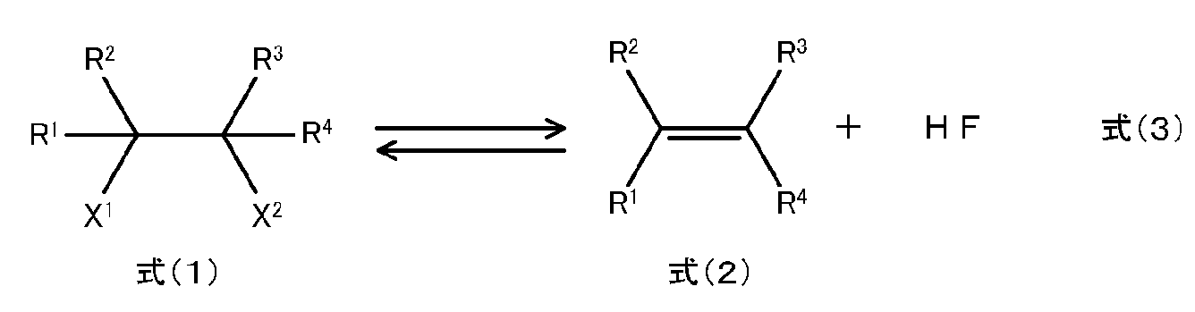
- step (I) the reaction in which the hydrofluoroolefin represented by the formula (2) is generated from the hydrofluorocarbon represented by the formula (1) can be represented by the following reaction formula (3).
- the hydrofluorocarbon represented by the formula (1) and the hydrofluoroolefin represented by the formula (2) have 2 to 3 carbon atoms.
- the combination of the hydrofluorocarbon represented by the formula (1) as the raw material and the hydrofluoroolefin represented by the formula (2) as the target is, for example, trifluoroethane (1,1,1-trifluoroethane (HFC-143a), 1,1,2-trifluoroethane (HFC-143), or a mixture of HFC-143a and HFC-143) and 1,1-difluoroethylene ( HFO-1132a), tetrafluoroethane (1,1,2,2-tetrafluoroethane (HFC-134), HFC-134a, or a mixture of HFC-134 and HFC-134a) and HFO-1123, pentafluoropropane ( HFC-245cb, HFC-245eb, or HFC-2 5cb and a mixture of HFC-245eb) and HFO-1234yf, pentafluoropropane (1,1,1,
- HFC-134a to HFO-1123, pentafluoropropane can be efficiently produced from the hydrofluoroolefin represented by the formula (2).
- HFO-1234yf is produced from a mixture of 245cb and HFC-245eb, respectively.
- the compound name or abbreviation indicates an E-form and / or a Z-form.
- the manufacturing method of the hydrofluoroolefin of this invention is the method of performing process (I) and process (II) in this order, process (I) and process (II) will be continuously performed by the continuous process. It may be a method, or may be an all-batch type manufacturing method in which both step (I) and step (II) are batch steps.
- the process (I) may be a continuous process or a batch process.
- the process (II) may be a continuous process or a batch process as in the process (I). From the viewpoint of shortening the maintenance time and increasing productivity, the step (II) is preferably a continuous process.
- the method for producing hydrofluoroolefin of the present invention is a step of separating hydrogen fluoride contained in the first gas composition (hereinafter also referred to as step (A)) between step (I) and step (II). ) May further be included.
- step (A) By separating the hydrogen fluoride produced in the reaction formula (3) by the step (A), purification of the hydrofluoroolefin represented by the formula (2) as a target product or the formula (1)
- the load of the process for recovering hydrofluorocarbon and carbon dioxide can be reduced, and the productivity is excellent.
- the production method may be an all-continuous production method or all batches.
- the manufacturing method of a formula may be sufficient, and the one part process of these processes may be a batch type process, and the one part continuous manufacturing method by which other processes are performed continuously may be sufficient.
- the step (A) is preferably a continuous process.
- step (I), step (II) and step (A) will be further described.
- step (I) the hydrofluorocarbon represented by the formula (1) in the raw material gas is converted into the hydrofluoroolefin represented by the formula (2) in the presence of carbon dioxide.
- the conversion from the hydrofluorocarbon represented by the formula (1) to the hydrofluoroolefin represented by the formula (2) is preferably performed by contacting the hydrofluorocarbon represented by the formula (1) with a catalyst.
- process (I) in the manufacturing method of the hydrofluoroolefin of this invention is not limited to such an aspect.
- the raw material gas includes a hydrofluorocarbon represented by the formula (1) as a raw material and a dilution gas of the hydrofluorocarbon.
- the source gas may contain other compounds in addition to the hydrofluorocarbon represented by the formula (1) and the dilution gas as long as the effects of the present invention are not impaired.
- the source gas may be partially liquefied under high pressure.
- the source gas is preferably a gas composed only of the hydrofluorocarbon represented by the formula (1), or a gas composition having a hydrofluorocarbon content represented by the formula (1) of 50 mol% or more.
- the dilution gas refers to a gas for diluting the raw material.
- the raw material gas may contain a hydrofluoroolefin represented by the formula (2). Therefore, the second gas composition obtained by various hydrofluoroolefin production methods including the hydrofluoroolefin production method of the present invention contains 50 mol% or more of the hydrofluorocarbon represented by the formula (1).
- the second gas composition can be used as a raw material gas in the step (I).
- process (I) is a continuous process
- the raw material gas containing the hydrofluorocarbon represented by Formula (1) as a reaction component to the reaction field (for example, heated reactor)
- raw material gas And the catalyst may be supplied continuously, or only one of the source gas and the catalyst may be supplied continuously, and the other may be supplied in a batch system.
- the catalyst is supplied batchwise to the reactor, and then the raw material gas containing the hydrofluorocarbon represented by the formula (1) is continuously supplied to the reactor. It is preferable.
- carbon dioxide refers to carbon dioxide alone or a gas containing 99.9% or more of carbon dioxide. Carbon dioxide is used as a diluting gas for the hydrofluorocarbon represented by formula (1) in step (I).
- Carbon dioxide may be added in the step (I), or carbon dioxide generated as a by-product in the process of producing the hydrofluoroolefin may be used in the step (I) as all or part of the diluent gas. . Carbon dioxide is preferably added from the viewpoint that the amount of dilution gas in the step (I) can be adjusted.
- gaseous carbon dioxide (hereinafter also referred to as carbon dioxide) may be used alone, or a mixture containing carbon dioxide and oxygen, nitrogen, helium, argon, carbon tetrachloride, etc. in an arbitrary ratio. Gas may be used.
- Other compounds are compounds other than the hydrofluorocarbon represented by the formula (1), carbon dioxide, and the hydrofluoroolefin represented by the formula (2).
- Other compounds include, for example, impurities derived from the production method, dilution gases other than carbon dioxide, and the like.
- impurities examples include trifluoromethane (HFC-23), HFC-32, HFC-134, HFC-143a, HFO-1132a, trans-1,2-difluoroethylene (HFO-1132 (E)), cis-1,2 -Difluoroethylene (HFO-1132 (Z)), vinyl fluoride (HFO-1141), HFO-1234yf, methane, ethane, ethylene, propane, propylene, acetone, oxygen, fluorine, hydrogen fluoride, chlorine, hydrogen chloride, etc. Is mentioned.
- Dilution gases other than carbon dioxide include nitrogen and carbon tetrachloride.
- the molar ratio (hydrofluorocarbon / carbon dioxide) of the hydrofluorocarbon represented by Formula (1) and a carbon dioxide is represented. It is preferable that it is 0.3-99.7 or more and 99.5 / 0.5 or less.
- the molar ratio is more preferably 5/95 or more and 70/30 or less, and more preferably 5/95 or more and 50/50 or less in terms of catalyst deterioration, carbon dioxide removal rate, alkali solution cost, and the like. Is most preferred.
- the hydrofluoroolefin represented by the formula (2) is contained in the raw material gas in the step (I)
- the hydrofluoroolefin represented by the formula (2) contained in the raw material gas is represented by the reaction formula (3).
- the equilibrium reaction represented the reverse reaction of the reaction produced by the hydrofluoroolefin represented by the formula (2) occurs.
- the hydrofluoroolefin represented by the formula (2) is not contained in the raw material gas.
- the content ratio of the hydrofluoroolefin in the raw material gas is preferably 0.001 mol% or more and 20 mol% or less, and 0.001 mol% or more. 10 mol% or less is more preferable, and 0.001 mol% or more and 5 mol% or less is the most preferable.
- Other compounds in the raw material gas are used from the viewpoint of suppressing side reactions caused by catalyst degradation and reducing the load of the subsequent purification process of hydrofluoroolefin by suppressing the generation of unnecessary by-products. , Preferably not included.
- 0.001 mol% to 10 mol% is preferable, 0.001 mol% to 5 mol% is more preferable, and 0.001 mol% to 1 mol% is preferable. The following are most preferred.
- the catalyst used in the step (I) has a catalytic action for the dehydrofluorination reaction of the hydrofluorocarbon represented by the formula (1).
- the catalyst include simple metals, metal oxides, metal halides, and the like. Among these substances, a metal oxide or a metal halide is preferable because the hydrofluorocarbon represented by the formula (1) can be efficiently converted into the hydrofluoroolefin represented by the formula (2).
- a catalyst may be used individually by 1 type and may use 2 or more types together.
- Examples of the metal constituting the metal simple substance, metal oxide, and metal halide include transition metal elements, Group 12 metal elements, Group 13 metal elements, and metal silicon. Among these, Group 6 metal elements, Group 8 metal elements, Group 10 metal elements, Group 12 metal elements, and Group 13 metal elements are preferable, and chromium, iron, zinc, and aluminum are more preferable.
- the single metal may be one of the above metals or an alloy of two or more metals.
- the metal oxide may be one kind of the above-mentioned metal oxide or a complex oxide of two or more kinds of metals.
- the metal halide may be one of the above-mentioned metal halides or a composite halide of two or more metals.
- the catalyst include cobalt, nickel, palladium, chromium oxide, aluminum oxide, zinc oxide, iron fluoride, aluminum fluoride, aluminum chloride, chromium fluoride, chromium chloride, and silicon oxide.
- Silica oxide is preferably silica gel.
- aluminum oxide, aluminum fluoride, and chromium oxide are preferable in that the hydrofluorocarbon represented by the formula (1) can be efficiently converted into the hydrofluoroolefin represented by the formula (2).
- the specific surface area (hereinafter referred to as BET specific surface area) of the catalyst measured by the BET method is preferably 50 m 2 / g or more and 400 m 2 / g or less, and more preferably 200 m 2 / g or more and 400 m 2 / g or less. If the BET specific surface area of the catalyst is in the above range, the hydrofluorocarbon represented by the formula (1) reacts at a high reaction rate, the reaction efficiency is good, and the density of the catalyst particles is not too small. Therefore, it is hard to scatter and has good handling properties.
- the catalyst may be supported on a carrier.
- the carrier include an alumina carrier, a zirconia carrier, a silica carrier, a silica alumina carrier, a carbon carrier represented by activated carbon, a barium sulfate carrier, and a calcium carbonate carrier.
- the activated carbon include activated carbon prepared from raw materials such as wood, charcoal, fruit glass, coconut shell, peat, lignite and coal.
- the catalyst is preferably activated in advance from the viewpoint of improving the conversion rate.
- the activation treatment method include a method in which the catalyst is brought into contact with the activation treatment agent with heating or without heating.
- the activation treatment agent include oxygen, hydrogen fluoride, hydrogen chloride, fluorine-containing compounds and the like, and among these, fluorine-containing compounds are preferable.
- the fluorine-containing compound include HFC-143, HFC-143a, HFC-134, HFC-134a, HFC-245cb, HFC-245eb, HFC-245fa, HFO-1132a, HFO-1132 (E), and HFO-1132.
- step (Z) HFO-1123, HFO-1234yf, HFO-1234ze, trichlorofluoromethane (HFC-11), dichlorofluoromethane (HFC-21), chlorodifluoromethane (HFC-22), HFC-32, tetrafluoroethylene (FO-14), HFC-125 and the like.
- HFC-11 dichlorofluoromethane
- HFC-21 dichlorofluoromethane
- chlorodifluoromethane HFC-22
- HFC-32 tetrafluoroethylene
- HFC-125 tetrafluoroethylene
- the catalyst is preferably subjected to a reactivation treatment in addition to the activation treatment before the reaction. That is, the activity of the catalyst is reduced in the conversion reaction, and the conversion rate of the hydrofluorocarbon represented by the formula (1) as the raw material component and the selectivity of the hydrofluoroolefin represented by the formula (2) as the target product are When it falls, it is preferable to reactivate the catalyst. It is preferable to recycle the catalyst by regenerating the activity of the catalyst by reactivation treatment.
- Examples of the reactivation treatment method include a method in which the used catalyst is brought into contact with the reactivation treatment agent under heating or non-heating as in the above-described activation treatment performed before use.
- As the reactivation treatment agent oxygen, hydrogen fluoride, hydrogen chloride, a fluorine-containing compound, or the like can be used.
- the fluorine-containing compound include HFC-143, HFC-143a, HFC-134, HFC-134a, HFC-245cb, HFC-245eb, HFC-245fa, HFO-1132a, HFO-1132 (E), and HFO-1132.
- an inert gas such as nitrogen, argon or helium in order to dilute the activation treatment agent from the viewpoint of suppressing side reactions and improving the durability of the catalyst.
- the catalyst may be in contact with the raw material gas in a solid state (solid phase) or dispersed in a liquid medium in which the catalyst can be dispersed. You may contact with source gas by (liquid phase).
- the liquid medium for dispersing the catalyst include water, alcohols such as methanol and ethanol, chlorinated solvents such as carbon tetrachloride, N, N-dimethylformamide, N, N-dimethylacetamide, dimethyl sulfoxide, tetra
- examples include ethylene glycol dimethyl ether, triethylene glycol dimethyl ether, diethylene glycol dimethyl ether, and propylene glycol monomethyl ether monoacetate.
- Step (I) in the method for producing hydrofluoroolefin is not limited to such an embodiment.
- the flow rate per unit time of each gas phase component of the source gas and the dilution gas is controlled, so that It is preferable to control the content ratio of the hydrofluorocarbon represented by formula (1) and the diluent gas.
- the shape and structure of the reactor for reacting the raw material gas with the catalyst are not particularly limited as long as they can withstand the temperature and pressure described later.
- the reactor include a cylindrical vertical reactor.
- the material of the reactor include glass, iron, nickel, iron or an alloy containing nickel as a main component.
- the reactor may include heating means such as an electric heater for heating the inside of the reactor.
- the solid phase catalyst charged into the reactor may be accommodated in either a fixed bed type or a fluidized bed type.
- a fixed floor type either a horizontal fixed floor type or a vertical fixed floor type may be used.
- the vertical fixed bed type is preferred because it is easy to prevent the concentration distribution of each component due to the difference in specific gravity.
- the raw material gas may be supplied to the reactor at room temperature, but in order to increase the reactivity in the reactor, it is preferable to supply the raw material gas after heating (preheating) before supplying it to the reactor. .
- the raw material gas is preferably heated to a temperature of 50 ° C. or higher and 400 ° C. or lower and then supplied to the reactor.
- the raw material gas supplied to the reactor comes into contact with the catalyst forming a solid phase in the reactor.
- the temperature of the raw material gas in the reactor is preferably 200 ° C. or higher and 1200 ° C. or lower from the viewpoint of improving the reactivity and improving the life of the catalyst. Furthermore, the temperature of the raw material gas in the reactor is more preferably 300 ° C. or higher and 1000 ° C. or lower from the viewpoint of reaction efficiency, suppression of side reactions, and production facilities.
- the pressure in the reactor is not a pressure near the critical point, and specifically, it is preferably ⁇ 0.1 MPa to 2.0 MPa, more preferably ⁇ 0.1 MPa to 0.5 MPa in terms of gauge pressure.
- the contact time between the raw material gas and the catalyst in the reactor is preferably from 0.1 seconds to 500 seconds, more preferably from 0.5 seconds to 50 seconds, and particularly preferably from 5 seconds to 30 seconds.
- step (I) a first gas composition containing a hydrofluoroolefin represented by the formula (2), carbon dioxide, and an unreacted hydrofluorocarbon represented by the formula (1) as an outlet gas of the reactor. Can be obtained.
- the first gas composition includes other substances in the step (I).
- the compound and other components that are by-products generated in the step (I) may be included.
- the hydrofluorocarbon represented by the formula (1) is HFC-134a
- the hydrofluoroolefin represented by the formula (2) is HFO-1123.
- step (II) carbon dioxide is separated from the first gas composition to obtain a second gas composition having an increased content of hydrofluoroolefin.
- the method for separating carbon dioxide is not particularly limited, and can be arbitrarily selected according to reaction conditions and reaction products.
- a chemical absorption method in which carbon dioxide is absorbed in an alkaline solution a physical absorption method in which carbon dioxide is physically dissolved in an absorbing solution under high pressure and low temperature
- an adsorption separation method in which carbon dioxide is adsorbed on a porous adsorbent examples include a membrane separation method in which carbon dioxide is separated by passing through a separation membrane, and a separation method in which carbon dioxide is in a solid state under high pressure and low temperature.
- These methods may be performed by a single method, or a plurality of methods may be combined. When it is carried out by a single method, it may be a one-step reaction or may be carried out in several steps.
- a method for separating carbon dioxide a chemical absorption method in which carbon dioxide is absorbed in an alkaline solution is preferable.
- hydrogen fluoride may be separated in addition to carbon dioxide.
- the alkaline solution used in step (II) is not particularly limited as long as it can separate carbon dioxide contained in the first gas composition. It is arbitrarily selected according to the thing. At this time, carbon dioxide contained in the first gas composition can be separated from the hydrofluoroolefin by bringing the first gas composition into contact with the alkaline solution.
- the alkaline solution preferably contains an inorganic base or organic base whose pKa of the conjugate acid is larger than 6, and more preferably contains an inorganic base or organic base whose pKa of the conjugate acid is larger than 9.
- the inorganic base and the organic base contained in the alkaline solution may be used alone or in combination of two or more.
- pKa is the acidity of the base conjugate acid in water.
- the alkaline solution is preferably an aqueous solution.
- Examples of the inorganic base include alkali metal alkoxide, alkaline earth metal alkoxide, tetraalkylammonium hydroxide, alkali metal hydroxide, alkaline earth metal hydroxide and the like.
- Inorganic bases include sodium hydroxide, potassium hydroxide, magnesium hydroxide, calcium hydroxide, sodium oxide, potassium oxide, magnesium oxide, calcium oxide, lithium hydroxide, potassium bicarbonate, potassium carbonate, sodium carbonate, sodium bicarbonate Magnesium hydrogen carbonate, magnesium carbonate, calcium hydrogen carbonate and calcium carbonate are preferred, and sodium hydroxide, potassium hydroxide, calcium oxide and potassium carbonate are more preferred from the viewpoint of cost.
- organic base examples include alkylamines, alkanolamines, polyamines, cyclic amines, amino acids, aminosulfonic acids and salts thereof.
- trialkylamines are preferable.
- examples of the trialkylamine include methyldiethylamine, triethylamine, tripropylamine, tributylamine and the like.
- alkanolamines monoalkanolamines, dialkanolamines, and trialkanolamines are preferable.
- Monoalkanolamines include monomethanolamine, monoethanolamine, n-propanolamine, isopropanolamine, 2-methylaminoethanol, 2-ethylaminoethanol, 2-propylaminoethanol, 2-amino-2-methyl-1- Examples include propanol, 2-isopropylaminoethanol, 3-piperidinemethanol, 3-quinuclidinol, 2-dimethylaminoethanol, and 2-diethylaminoethanol.
- dialkanolamines examples include diethanolamine, N-methyldiethanolamine, diglycolamine, diisopropanolamine, and 3-piperidino 1,2-propanediol.
- An example of the trialkanolamine is triethanolamine.
- Polyamines are preferably xylylenediamine, ethylenediamine, triethylenediamine, and diethylenetriamine.
- cyclic amines piperazine, piperidine and pyrrolidine are preferable.
- amino acids As the amino acids, ⁇ -amino acids and ⁇ -amino acids are preferable.
- ⁇ -amino acids include N, N-dimethylglycine, N-methylalanine, and 2-methylalanine.
- ⁇ -amino acids include ⁇ -alanine, 3-methylaminopropionic acid, and iminodipropionic acid.
- the aminosulfonic acid is preferably ⁇ -aminosulfonic acid or ⁇ -aminosulfonic acid.
- ⁇ -aminosulfonic acid include aminomethanesulfonic acid.
- ⁇ -aminosulfonic acid include 2-aminoethanesulfonic acid and 2- (methylamino) ethanesulfonic acid.
- triethylamine, tributylamine, monoethanolamine, n-propanolamine, and N-methyldiethanolamine are more preferable. From the viewpoint of cost, triethylamine, monoethanolamine, n-propanolamine, and N-methyldiethanolamine are most preferable. .
- the concentration of the alkali solution is preferably 5% by mass or more and 60% by mass or less, and more preferably 10% by mass or more and 60% by mass or less.
- the temperature of the alkaline solution is preferably 5 ° C. or higher and 60 ° C. or lower.
- the alkaline solution may contain a phosphoric acid-based anticorrosive, a silicone-based antifoaming agent, an antioxidant, an absorption accelerator, and the like.
- the absorbent used in step (II) is not particularly limited as long as it can separate carbon dioxide contained in the first gas composition, and the reaction conditions and reaction generation are not limited. It is arbitrarily selected according to the thing.
- Absorbents include methanol, polyethylene glycol, glyme, sulfolane, ionic liquids ([R, R′—N 2 C 3 H 3 ] + and [R—NC 5 H 5 ] + , PF 6 ⁇ and BF 4 ⁇ . Combination).
- One type of absorbent may be used alone, or two or more types may be used in combination.
- the adsorbent used in step (II) is not particularly limited as long as it can separate carbon dioxide contained in the first gas composition, and the reaction conditions and reaction generation are not limited. It is arbitrarily selected according to the thing.
- the adsorbent include porous bodies such as zeolite and activated carbon.
- One adsorbent may be used alone, or two or more adsorbents may be used in combination.
- the separation membrane used in step (II) is not particularly limited as long as it can separate carbon dioxide contained in the first gas composition. Reaction conditions and reaction generation It is arbitrarily selected according to the thing.
- the separation membrane include polymer membranes such as polyamide amine dendrimers, ceramic membranes, carbon membranes, and impregnated liquid membranes.
- a separation membrane may be used individually by 1 type, and may use 2 or more types together.
- the carbon dioxide separated in step (II) can be recovered.
- the recovery method varies depending on the carbon dioxide separation method. For example, in the case of a chemical absorption method, carbon dioxide is released and recovered by heating an absorbing solution such as an alkaline solution, and in the case of a physical absorption method, carbon dioxide is obtained by reducing the pressure and heating the absorbing solution.
- a method of recovering by adsorbing the adsorbent under a low pressure and desorbing carbon dioxide can be mentioned.
- the recovered carbon dioxide can be reused again as the diluent gas in step (I).
- step (II) a second gas composition containing the hydrofluoroolefin represented by formula (2) and the unreacted hydrofluorocarbon represented by formula (1) can be obtained.
- the second gas composition includes other compounds in the step (I), You may include the same compound and component as another component.
- step (II) by selectively separating the carbon dioxide contained in the first gas composition, the content ratio of the hydrofluoroolefin in the second gas composition is changed to that in the first gas composition. It is higher than the content of hydrofluoroolefin.
- the second gas composition can be used as it is for various applications, and is preferably further purified.
- the purification method include known methods such as distillation, adsorption, washing with an acidic aqueous solution, a basic aqueous solution or a neutral aqueous solution.
- Substances other than the hydrofluoroolefin represented by the formula (2) contained in the second gas composition can be removed by a known means and separated to a desired degree.
- the purification method is a method of distillation under normal pressure, increased pressure or reduced pressure. By carrying out distillation under such pressure, a high-purity hydrofluoroolefin can be obtained.
- the unreacted hydrofluorocarbon represented by the formula (1) separated from the second gas composition can be recycled as a part of the raw material gas in the step (I).
- the method for producing a hydrofluoroolefin of the present invention has a step (A) for separating hydrogen fluoride contained in the first gas composition between the step (I) and the step (II). Is preferred.
- the amount of hydrogen fluoride separated in the step (II) described above is very small compared to the amount of hydrogen fluoride separated in the step (A).
- the first gas composition may be supplied to the step (A) as it is, but another processing step is provided between the step (I) and the step (A), and the first gas composition is provided for the first gas composition.
- the other treatment is a treatment other than the separation of hydrogen fluoride and carbon dioxide and a treatment that does not change the composition of substances other than moisture contained in the first gas composition. Examples of other treatments include storage in a tank, compression with a compressor, heating, cooling, water removal, and the like.
- Examples of the method for separating hydrogen fluoride from the first gas composition include methods such as distillation, adsorption, and two-phase separation.
- Distillation is a method of separating hydrogen fluoride by distilling the first gas composition. Although distillation can be carried out under normal pressure, under pressure or under reduced pressure, it is preferably carried out under pressure from the viewpoint of improving the separation efficiency.
- Adsorption is a method in which the first gas composition is brought into contact with an adsorbent and hydrogen fluoride is adsorbed onto the adsorbent and separated.
- the adsorbent may form a solid phase or may be in a state (liquid phase) dispersed in a liquid medium in which the adsorbent does not dissolve.
- sodium fluoride, potassium fluoride, zeolite, activated carbon and the like can be used.
- Sodium fluoride is particularly preferable because hydrogen fluoride can be efficiently separated.
- the first gas composition is converted into a liquid phase under pressure, and the organic phase containing the hydrofluoroolefin represented by the formula (2), carbon dioxide, and the hydrofluorocarbon represented by the formula (1).
- the acid phase containing hydrogen fluoride are separated into two phases, and the phase-separated acid phase is separated.
- a gas composition having a lower content of hydrogen fluoride than that of the first gas composition is obtained. That is, by the step (A), the content ratio of hydrogen fluoride is low, and the hydrofluoroolefin represented by the formula (2), carbon dioxide, and the hydrofluorocarbon represented by the unreacted formula (1) are contained. A gas composition is obtained.
- the manufacturing method of the hydrofluoroolefin of this invention has a process (A)
- the said gas composition can be used as said 1st gas composition.
- the content ratio of acidic components such as hydrogen chloride and carbon dioxide, and the content ratio of compounds other than acidic components contained in the other compounds and other components are the first. May be lower than one gas composition.
- the amount of carbon dioxide separated in step (A) is very small compared to the amount of carbon dioxide separated in step (II).
- the gas composition obtained at the step (A) may be supplied to the step (II) as it is, another processing step is provided between the step (A) and the step (II), and the gas composition What processed the other thing to a thing may be supplied to process (II).
- the other treatments are treatments other than the separation of carbon dioxide and treatments that do not change the composition of substances other than moisture contained in the gas composition. Examples of other treatments include storage in a tank, compression with a compressor, heating, cooling, water removal, and the like.
- FIG. 1 is a schematic view showing an example of a reaction apparatus used in the method for producing a hydrofluoroolefin of the present invention.
- the reaction apparatus 1 includes a reactor 2 having heating means such as an electric heater for performing the step (I), and a carbon dioxide trap 3 for performing the step (II).
- heating means such as an electric heater for performing the step (I)
- carbon dioxide trap 3 for performing the step (II).
- installation of a heating means is not essential.
- FIG. 1 demonstrates the aspect using the chemical absorption method which uses an alkaline solution, the carbon dioxide separation method in the manufacturing method of the hydrofluoroolefin of this invention is not limited to such an aspect.
- the catalyst 5 is accommodated so as to form a vertical fixed bed. Further, the upper part on the inlet side of the reactor 2 is connected to a preheating mixer 6 equipped with heating means such as an electric heater by a raw material gas supply line 7.
- the source gas supply line 7 is preferably provided with heating means such as an electric heater.
- the raw material gas may be supplied from the upper part to the lower part of the reactor 2, or the raw material gas may be shared from the lower part to the upper part of the reactor 2.
- the preheating mixer 6 is connected with a hydrofluorocarbon supply line 8 for supplying the hydrofluorocarbon represented by the formula (1) and a carbon dioxide supply line 9 for supplying carbon dioxide as a diluent gas.
- Hydrofluorocarbon and carbon dioxide represented by the formula (1) are introduced into the preheating mixer 6 through the hydrofluorocarbon supply line 8 and the carbon dioxide supply line 9, respectively, mixed in the preheating mixer 6 and heated to a predetermined temperature.
- the raw material gas is supplied to the reactor 2 through the raw material gas supply line 7.
- the hydrofluorocarbon supplied to the reactor 2 comes into contact with the catalyst 5 in the presence of carbon dioxide, and is converted into a hydrofluoroolefin represented by the formula (2).
- the 1st gas composition containing the hydrofluoro olefin represented by Formula (2), the carbon dioxide, hydrogen fluoride, and the hydrofluorocarbon represented by the unreacted Formula (1) is obtained.
- the hydrofluorocarbon supply line 8 and the carbon dioxide supply line 9 are connected before being connected to the preheating mixer 6, and after mixing the hydrofluorocarbon represented by the formula (1) and carbon dioxide, the preheating mixer. 6 may be supplied. Further, a preheater (preheater) equipped with an electric heater or the like is installed in at least one of the hydrofluorocarbon supply line 8 and the carbon dioxide supply line 9, and is expressed by the formula (1) supplied through the line where the preheater is installed. Alternatively, at least one of hydrofluorocarbon and carbon dioxide may be preheated and then supplied to the preheating mixer 6.
- the lower part on the outlet side of the reactor 2 is connected to a hydrogen fluoride trap 4 filled with an adsorbent for adsorbing hydrogen fluoride by a reactor outlet line 10 equipped with heating means such as an electric heater. .
- the first gas composition obtained in the reactor 2 is supplied to the hydrogen fluoride trap 4 and passes through the hydrogen fluoride trap 4 filled with the adsorbent so as to be contained in the first gas composition. Hydrogen fluoride is adsorbed by the adsorbent. And the 1st gas composition which removed hydrogen fluoride is obtained.
- the outlet of the hydrogen fluoride trap 4 is connected to a carbon dioxide trap 3 containing an alkaline solution by an outlet line 11.
- the first gas composition that has passed through the hydrogen fluoride trap 4 is supplied to the carbon dioxide trap 3, and the first gas composition is included in the first gas composition by bubbling in the alkaline solution.
- Carbon dioxide reacts with alkaline solution.
- the carbon dioxide contained in a 1st gas composition is isolate
- the outlet of the carbon dioxide trap 3 is connected to a dehydrator 13 by an outlet line 12.
- the second gas composition obtained by the carbon dioxide trap 3 is supplied to the dehydrator 13 and water contained in the second gas composition is removed.
- the second gas composition from which moisture has been removed by the dehydrator 13 is collected in the sampling bag 14, and then the components contained in the second gas composition are analyzed by the analyzer 15 such as gas chromatography (GC).
- GC gas chromatography
- the method for producing a hydrofluoroolefin of the present invention even if the boiling point of the hydrofluoroolefin is low, it is possible to easily separate the hydrofluoroolefin and carbon dioxide as a diluent gas. As a result, the manufacturing cost can be reduced and the productivity of the hydrofluoroolefin can be increased.
- Hydrofluoroolefins produced by the production method of the present invention are used as refrigerants in place of greenhouse gases HFC-32 and HFC-125, and have functionalities such as piezoelectric elements and films. It is useful as a raw material monomer for materials and as an intermediate for synthesis.
- reaction apparatus (1) the reaction apparatus shown in FIG. 1 (hereinafter referred to as reaction apparatus (1)) was used.
- the reactor 2 was a vertical fixed bed reactor made of SUS316L (JIS standard) and having an inner diameter of 22.66 mm and a height of 300 mm.
- the catalyst 5 shown in each Example and Comparative Example was packed at a height of 100 mm.
- the inside of the reactor 2 was heated by an electric furnace.
- the raw material gas supply line 7 connected to the inlet side of the reactor 2 was heated by a ribbon heater so as to be in the range of 100 ° C. or higher and 120 ° C. or lower.
- HFC-134a which is the hydrofluorocarbon represented by the formula (1)
- carbon dioxide which is a diluent gas
- the reactor outlet line 10 connected to the outlet side of the reactor 2 is heated by a ribbon heater to a range of 100 ° C. or more and 120 ° C. or less, and is fluorinated with 30 g of 1/16 inch sodium fluoride pellets.
- the outlet line 11 connected to the outlet side of the hydrogen fluoride trap 4 was connected to the carbon dioxide trap 3 containing a 20% by mass potassium hydroxide aqueous solution.
- the outlet line 12 connected to the outlet side of the carbon dioxide trap 3 was connected to a dehydrator 13 filled with 120 g of pellet-shaped molecular sieves 3A (manufactured by Junsei Chemical Co., Ltd., 1/8 inch pellets).
- the second gas composition that has passed through the dehydrator 13 is collected by a sampling bag 14 made of polyvinylidene fluoride (PVdF) connected to the dehydrator 13, and then the composition analysis of the second gas composition is performed.
- the analyzer 15 is configured to perform the process.
- GC ⁇ Analysis conditions>
- DB-1 manufactured by Agilent Technologies, length 60 m ⁇ inner diameter 250 ⁇ m ⁇ thickness 1 ⁇ m
- the detector used was FID.
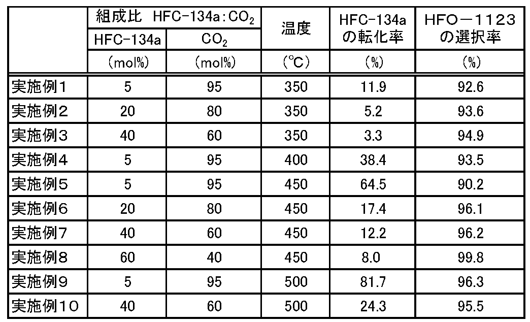
- Example 1 The reactor 2 of the reactor (1) is charged with 40 g of an alumina catalyst (manufactured by JGC Catalysts & Chemicals, trade name: ACBM-1, shape: 2 mm spherical), and nitrogen gas is supplied at 300 mL / min. It was dried by heating at 350 ° C. for 48 hours.
- an alumina catalyst manufactured by JGC Catalysts & Chemicals, trade name: ACBM-1, shape: 2 mm spherical
- the internal temperature of the reactor 2 was set to 350 ° C., and a mixed gas in which 5 mol% of HFC-134a and 95 mol% of nitrogen were mixed was supplied to the reactor 2 at a linear velocity of 1 cm / s. HFC-134a and nitrogen were allowed to flow continuously, and after 4 hours, it was confirmed that the composition of the outlet gas that had passed through the hydrogen fluoride trap 4 filled with sodium fluoride pellets was stable.
- the temperature inside the reactor 2 was set to 350 ° C., and a raw material gas mixed with 5 mol% of HFC-134a and 95 mol% of carbon dioxide as a diluent gas was supplied to the reactor 2.
- HFC-134a and carbon dioxide were continuously flowed, and it was confirmed that the composition of the outlet gas that passed through the hydrogen fluoride trap 4 (hereinafter referred to as NaF passage outlet gas) was stable.
- NaF passage outlet gas is supplied to the carbon dioxide trap 3 and the dehydrator 13, and the composition of the outlet gas that has passed through the carbon dioxide trap 3 and the dehydrator 13 (hereinafter referred to as KOH passage outlet gas) is stabilized for 2 hours.
- KOH passage outlet gas A sample of KOH passage outlet gas was taken each time.
- the alkaline aqueous solution in the carbon dioxide trap 3 was stirred with a stirring bar. At this time, the first gas composition that passed through the carbon dioxide trap 3 formed minute bubbles in the alkaline aqueous solution. In addition, the room temperature at the time of sample collection was 25 degreeC.
- the conversion rate of HFC-134a and the selectivity of HFO-1123 were determined as follows. .
- the molar ratio of each component in the KOH passage outlet gas is calculated by multiplying the area ratio of each component identified by GC by the detection sensitivity factor measured using a standard substance with a known composition ratio. did.
- the molar ratio of HFC-134a and carbon dioxide in the raw material gas was calculated from the flow rate ratio of HFC-134a and carbon dioxide.
- the conversion rate of HFC-134a refers to the ratio of HFC-134a converted to other components including HFO-1123 by the reaction and consumed.
- the conversion rate of HFC-134a is calculated by the following formula.
- the selectivity for HFO-1123 refers to the proportion of HFC-134a converted to HFO-1123.
- the selectivity of HFO-1123 is calculated by the following formula.
- the temperature inside the reactor is the temperature inside the reactor 2 and is an actual measurement value.
- the linear velocity is the linear velocity of the raw material gas supplied to the reactor.
- Examples 2 to 10 The reaction was continuously performed in the same manner as in Example 1 except that the reaction conditions were changed as shown in Table 1. Then, the conversion rate of HFC-134a and the selectivity of HFO-1123 were determined in the same manner as in Example 1. The obtained results are shown in Table 1.
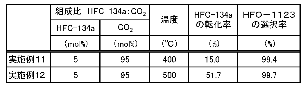
- Examples 11 and 12 The reactor 2 of the reactor (1) was filled with 40 g of aluminum trifluoride (manufactured by Kanto Chemical Co., Ltd., trade name: Aluminium Trifluoride, shape: powder) as a catalyst, and the reaction conditions were changed as shown in Table 2. The reaction was continuously carried out in the same manner as in Example 1 except that. Then, the conversion rate of HFC-134a and the selectivity of HFO-1123 were determined in the same manner as in Example 1. The obtained results are shown in Table 2.
- aluminum trifluoride manufactured by Kanto Chemical Co., Ltd., trade name: Aluminium Trifluoride, shape: powder
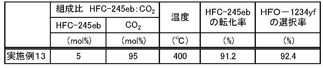
- Example 13 The reaction was continuously performed in the same manner as in Example 1 except that the composition of the source gas and the reaction conditions were changed as shown in Table 3.
- the conversion rate of HFC-245eb and the selectivity of HFO-1234yf were calculated from the following equations.
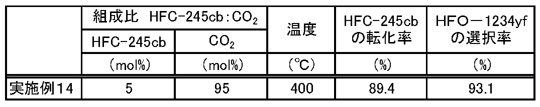
- Example 14 The reaction was continuously performed in the same manner as in Example 1 except that the composition of the source gas and the reaction conditions were changed as shown in Table 4.
- the conversion rate of HFC-245cb and the selectivity of HFO-1234yf were calculated from the following equations.
- Example 15 The reactor 2 of the reactor (1) is charged with 40 g of an alumina catalyst (manufactured by JGC Catalysts & Chemicals, trade name: ACBM-1, shape: 2 mm spherical), and nitrogen gas is supplied at 300 mL / min. It was dried by heating at 350 ° C. for 48 hours.
- an alumina catalyst manufactured by JGC Catalysts & Chemicals, trade name: ACBM-1, shape: 2 mm spherical
- the internal temperature of the reactor 2 was set to 350 ° C., and a mixed gas in which 5 mol% of HFC-134a and 95 mol% of nitrogen were mixed was supplied to the reactor 2 at a linear velocity of 1 cm / s. HFC-134a and nitrogen were allowed to flow continuously, and after 4 hours, it was confirmed that the composition of the outlet gas that had passed through the hydrogen fluoride trap 4 filled with sodium fluoride pellets was stable.
- the internal temperature of the reactor 2 was set to 450 ° C., and a raw material gas mixed with 5 mol% of HFC-134a and 95 mol% of carbon dioxide as a diluent gas was supplied to the reactor 2.
- a raw material gas mixed with 5 mol% of HFC-134a and 95 mol% of carbon dioxide as a diluent gas was supplied to the reactor 2.
- 5 hours after the composition of the NaF passage outlet gas is stabilized the sample of the NaF passage outlet gas is collected in the sampling bag connected to the outlet line 11, and then analyzed. Composition analysis was performed with an apparatus (not shown).
- the NaF passage outlet gas was supplied to the carbon dioxide trap 3 and the dehydrator 13, and a sample of the KOH passage outlet gas was collected 5 hours after the composition of the KOH passage outlet gas was stabilized.
- the alkaline aqueous solution in the carbon dioxide trap 3 was stirred with a stirring bar. At this time, the first gas composition that passed through the carbon dioxide trap 3 formed minute bubbles in the
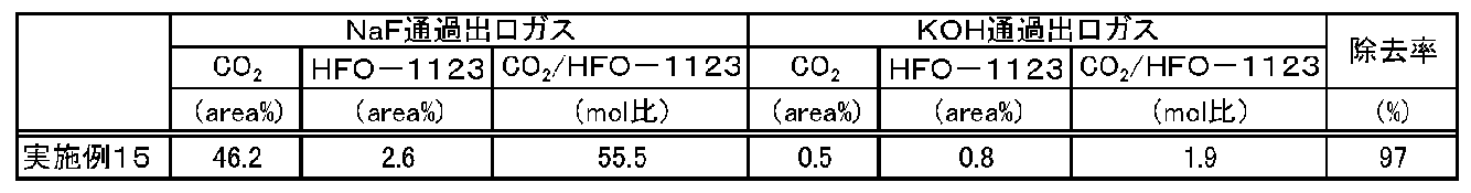
- Table 6 shows the results of evaluation by a gas chromatograph mass spectrometer.
- the molar ratio of CO 2 / HFO-1123 in Table 6 was obtained from a calibration curve calculated using a standard sample.
- DB-1 manufactured by Agilent Technologies, length 60 m ⁇ inner diameter 250 ⁇ m ⁇ thickness 1 ⁇ m
- the detector used was TCD.
- Table 6 shows that 97% of the carbon dioxide contained in the first gas composition could be separated by the alkaline aqueous solution.
- a hydrofluoroolefin having a low boiling point can be efficiently and stably produced from a hydrofluorocarbon having a low boiling point.
- carbon dioxide as a diluent gas can be easily separated with an alkaline solution as an inexpensive raw material, it is useful as an industrial production method.
- carbon dioxide which is considered to have an adverse effect on the global environment, is useful as a raw material, it can be said that it is a production method in consideration of the global environment.
Landscapes
- Chemical & Material Sciences (AREA)
- Organic Chemistry (AREA)
- Organic Low-Molecular-Weight Compounds And Preparation Thereof (AREA)
- Catalysts (AREA)
- Low-Molecular Organic Synthesis Reactions Using Catalysts (AREA)
Abstract
Description
[1]下記式(1)で表されるハイドロフルオロカーボンを二酸化炭素の存在下において下記式(2)で表されるハイドロフルオロオレフィンに転化し、前記ハイドロフルオロオレフィンと前記二酸化炭素とを含有する第1のガス組成物を得る工程と、前記第1のガス組成物に含まれる前記二酸化炭素を分離し、前記ハイドロフルオロオレフィンを含有する第2のガス組成物を得る工程とを有することを特徴とするハイドロフルオロオレフィンの製造方法;
CR1R2X1CR3R4X2 ・・・(1)
CR1R2=CR3R4 ・・・(2)
(上記式(1)および式(2)中、R1~R3は、それぞれ独立に水素原子またはフッ素原子であり、R4は、水素原子、フッ素原子、CH3、CH2F、CHF2またはCF3であり、R1~R4の合計のフッ素原子数は1以上であり、R1~R4の合計の水素原子数は1以上である。X1およびX2は水素原子またはフッ素原子であり、X1が水素原子であるときX2はフッ素原子、X1がフッ素原子であるときX2は水素原子である。)。
[2]前記第2のガス組成物を得る工程は、前記第1のガス組成物をアルカリ溶液と接触させる工程を含む、[1]のハイドロフルオロオレフィンの製造方法。
[3]前記アルカリ溶液は、共役酸のpKaが6より大きい無機塩基または有機塩基を含む、[2]のハイドロフルオロオレフィンの製造方法。
[4]前記無機塩基は、水酸化ナトリウム、水酸化カリウム、炭酸カリウムおよび酸化カルシウムからなる群より選択される少なくとも1種の塩基である、[3]のハイドロフルオロオレフィンの製造方法。
[5]前記有機塩基は、トリエチルアミン、トリブチルアミン、モノエタノールアミン、n-プロパノールアミンおよびN-メチルジエタノールアミンからなる群より選択される少なくとも1種の塩基である、[3]のハイドロフルオロオレフィンの製造方法。
[6]前記第1のガス組成物を得る工程における前記ハイドロフルオロカーボンと前記二酸化炭素とのモル比(ハイドロフルオロカーボン/二酸化炭素)は、0.3/99.7以上99.5/0.5以下である、[1]~[5]のいずれかのハイドロフルオロオレフィンの製造方法。
[7]前記ハイドロフルオロカーボンはHFC-134aであり、前記ハイドロフルオロオレフィンはHFO-1123である、[1]~[6]のいずれかのハイドロフルオロオレフィンの製造方法。
[8]前記ハイドロフルオロカーボンはHFC-245cbおよび/またはHFC-245ebであり、前記ハイドロフルオロオレフィンはHFO-1234yfである、[1]~[6]のいずれかのハイドロフルオロオレフィンの製造方法。
[9]前記第1のガス組成物を得る工程は、前記ハイドロフルオロカーボンと触媒とを接触させる工程を含む、[1]~[8]のいずれかのハイドロフルオロオレフィンの製造方法。
[10]前記触媒は、金属、金属酸化物および金属ハロゲン化物からなる群より選択される少なくとも1種の物質である、[9]のハイドロフルオロオレフィンの製造方法。
[11]前記触媒は、コバルト、ニッケル、パラジウム、酸化クロム、酸化アルミニウム、酸化亜鉛、フッ化鉄、フッ化アルミニウム、塩化アルミニウム、フッ化クロム、塩化クロムおよび酸化ケイ素からなる群より選択される少なくとも1種の物質である、[9]または[10]のハイドロフルオロオレフィンの製造方法。
[12]前記第1のガス組成物を得る工程において、前記ハイドロフルオロカーボンを前記ハイドロフルオロオレフィンに転化する温度は、200℃以上1200℃以下である、[1]~[11]のいずれかのハイドロフルオロオレフィンの製造方法。
工程(II):前記第1のガス組成物に含まれる前記二酸化炭素を分離し、前記ハイドロフルオロオレフィンを含有する第2のガス組成物を得る分離工程。
工程(I)では、二酸化炭素の存在下で、原料ガス中の式(1)で表されるハイドロフルオロカーボンを式(2)で表されるハイドロフルオロオレフィンに転化させる。式(1)で表されるハイドロフルオロカーボンから式(2)で表されるハイドロフルオロオレフィンへの転化は、式(1)で表されるハイドロフルオロカーボンを触媒と接触させて行うことが好ましい。以下、触媒を用いた態様について説明するが、本発明のハイドロフルオロオレフィンの製造方法における工程(I)は、このような態様に限定されない。
原料ガスは、原料である式(1)で表されるハイドロフルオロカーボン、および該ハイドロフルオロカーボンの希釈ガスを含む。さらに、原料ガスは、本発明の効果を損なわない範囲において、式(1)で表されるハイドロフルオロカーボンおよび希釈ガス以外に、その他の化合物を含んでもよい。また、原料ガスは、高圧下では一部液化していてもよい。原料ガスは、式(1)で表されるハイドロフルオロカーボンのみからなるガスであること、または式(1)で表されるハイドロフルオロカーボンの含有割合が50モル%以上のガス組成物であることが好ましい。なお、本明細書中において、希釈ガスとは、原料を希釈するためのガスをいう。
本発明において、特に記載のない限り、二酸化炭素とは、二酸化炭素単体または二酸化炭素を99.9%以上含有するガスをいう。二酸化炭素は、工程(I)において式(1)で表されるハイドロフルオロカーボンの希釈ガスとして使用する。
工程(I)で用いられる触媒は、式(1)で表されるハイドロフルオロカーボンの脱フッ化水素反応に対して触媒作用を有する。触媒としては、金属単体、金属酸化物、金属ハロゲン化物等が挙げられる。これらの物質の中でも、式(1)で表されるハイドロフルオロカーボンを効率よく式(2)で表されるハイドロフルオロオレフィンに転化できることから、金属酸化物または金属ハロゲン化物が好ましい。触媒は、1種を単独で用いてもよく、2種以上を併用してもよい。
工程(I)における原料ガスと触媒との接触において、触媒は、固体の状態(固相)で原料ガスと接触してもよいし、あるいは、触媒を分散可能な液状の媒体に分散された状態(液相)で原料ガスと接触してもよい。触媒を分散させる液状の媒体としては、例えば、水、メタノールやエタノール等のアルコール、四塩化炭素等の塩素系溶媒、N,N-ジメチルホルムアミド、N,N-ジメチルアセトアミド、ジメチルスルフォキシド、テトラエチレングリコールジメチルエーテル、トリエチレングリコールジメチルエーテル、ジエチレングリコールジメチルエーテル、プロピレングリコールモノメチルエーテルモノアセテート等が挙げられる。液状の媒体に分散された状態の触媒に原料ガスを接触させる場合は、原料ガスの圧力が高くなり、高温での反応が困難であることから、固相をなす触媒と原料ガスを接触させることが好ましい。
工程(I)で、原料ガスと触媒とを接触させて反応させる反応器としては、後述する温度および圧力に耐えることができるものであれば、形状および構造は特に限定されない。反応器は、例えば、円筒状の縦型反応器が挙げられる。反応器の材質としては、ガラス、鉄、ニッケル、鉄またはニッケルを主成分とする合金等が挙げられる。反応器は、反応器内を加熱する電気ヒータ等の加熱手段を備えてもよい。
工程(I)では、反応器の出口ガスとして、式(2)で表されるハイドロフルオロオレフィンと二酸化炭素と未反応の式(1)で表されるハイドロフルオロカーボンとを含む第1のガス組成物を得ることができる。第1のガス組成物は、目的物である式(2)で表されるハイドロフルオロオレフィン、二酸化炭素、未反応の式(1)で表されるハイドロフルオロカーボン以外に、工程(I)におけるその他の化合物や、工程(I)で生成される副生物であるその他の成分を含んでもよい。第1のガス組成物に含有されるその他の成分としては、例えば、式(1)で表されるハイドロフルオロカーボンがHFC-134aであり式(2)で表されるハイドロフルオロオレフィンがHFO-1123である場合にはHFO-1141、HFO-1132a、HFO-1132(Z)、HFO-1132(E)、HFC-134、HFC-143、HFC-134a、HFC-125、HFC-23、HFC-32、メタン、エチレン、エタン、プロピレン、プロパン等が挙げられる。
工程(II)では、第1のガス組成物から二酸化炭素を分離して、ハイドロフルオロオレフィンの含有割合の増加した第2のガス組成物を得る。二酸化炭素を分離する方法としては、特には限定されず、反応条件や反応生成物に応じて任意に選択できる。例えば、二酸化炭素をアルカリ溶液に吸収させる化学吸収法、高圧、低温下において、二酸化炭素を物理的に吸収液に溶解させる物理吸収法、多孔質の吸着剤に二酸化炭素を吸着させる吸着分離法、分離膜を通過させることにより二酸化炭素を分離する膜分離法、高圧、低温下で二酸化炭素を固体状態とする分離法などが挙げられる。これらの方法は、単一の方法で行ってもよいし、複数の方法を組合せてもよい。単一の方法で行う場合には、1段階反応でもよいし、数段階に分けて反応させてもよい。二酸化炭素を分離する方法としては、二酸化炭素をアルカリ溶液に吸収させる化学吸収法が好ましい。なお、分離方法によっては二酸化炭素に加えてフッ化水素も分離されることがある。
工程(II)において分離された二酸化炭素は、回収することができる。回収方法は二酸化炭素の分離方法によって異なる。例えば、化学吸収法の場合には、アルカリ溶液などの吸収液を加熱することにより二酸化炭素を放出させて回収する方法、物理吸収法の場合には、吸収液を減圧、加熱することにより二酸化炭素を放散させて回収する方法、吸着分離法の場合には、吸着剤を低圧下におき、二酸化炭素を脱着させて回収する方法等が挙げられる。回収された二酸化炭素は、再度工程(I)の希釈ガスとして再利用することが出来る。
工程(II)では、式(2)で表されるハイドロフルオロオレフィンと未反応の式(1)で表されるハイドロフルオロカーボンとを含む第2のガス組成物を得ることができる。第2のガス組成物は、目的物である式(2)で表されるハイドロフルオロオレフィンおよび未反応の式(1)で表されるハイドロフルオロカーボン以外に、上記工程(I)におけるその他の化合物やその他の成分と同じ化合物や成分を含んでもよい。工程(II)では、第1のガス組成物に含まれる二酸化炭素を選択的に分離することにより、第2のガス組成物中のハイドロフルオロオレフィンの含有割合は、第1のガス組成物中のハイドロフルオロオレフィンの含有割合よりも高い。
さらに、本発明のハイドロフルオロオレフィンの製造方法は、工程(I)と工程(II)との間に、第1のガス組成物中に含まれるフッ化水素を分離する工程(A)を有することが好ましい。工程(A)を有する場合、上述した工程(II)で分離されるフッ化水素の量は、工程(A)で分離されるフッ化水素の量に比べて非常に少ない。
図1は、本発明のハイドロフルオロオレフィンの製造方法に使用される反応装置の一例を示す概略図である。反応装置1は、工程(I)を実施するための電気ヒータ等の加熱手段を備えた反応器2と、工程(II)を実施するための二酸化炭素トラップ3を備える。なお、反応器2において、加熱手段の設置は必須ではない。また、必要に応じて、工程(I)と工程(II)との間に、工程(A)を実施するためのフッ化水素トラップ4を備えてもよい。図1では、アルカリ溶液を使用する化学吸収法を用いた態様について説明するが、本発明のハイドロフルオロオレフィンの製造方法における二酸化炭素の分離方法は、このような態様に限定されない。
実施例および比較例では、図1に示す反応装置(以下、反応装置(1)と示す。)を用いた。
反応装置(1)において、反応器2はSUS316L(JIS規格)製で内径22.66mm×高さ300mmの垂直固定床反応器を用いた。反応器2内には、各実施例および比較例で示す触媒5を、100mmの高さで充填した。また、反応器2内は、電気炉により加熱した。
分析装置15において、第2のガス組成物の組成分析には、GCを用いた。カラムは、DB-1(アジレント・テクノロジー株式会社製、長さ60m×内径250μm×厚さ1μm)を用いた。検出器はFIDを用いた。
線速度は空塔速度を意味し、原料ガスを流通する反応器がその内部に充填物を充填していない空塔であると仮定し、流量(体積流量)を空塔である反応器の断面積で割ることで算出した。なお、この線速度は1cm/sで実験を行った。
線速度(空塔速度)(cm/s)=流量(cm3/s)/断面積(cm2)
反応装置(1)の反応器2に、アルミナ触媒(日揮触媒化成社製、商品名:ACBM-1、形状:粒径2mm球状)の40gを充填し、窒素ガスを300mL/minで供給しながら350℃で48時間加熱して乾燥させた。
HFC-134aの転化率とは、反応によりHFC-134aがHFO-1123を含む他の成分に転化し消費された割合をいう。HFC-134aの転化率は、以下の式により算出される。
HFO-1123の選択率とは、反応したHFC-134aのうち、HFO-1123に転化した割合をいう。HFO-1123の選択率は、以下の式により算出される。
(HFO-1123)out/{1-(HFC-134a)out/(HFC-134a)in}×100
反応条件を表1に示すように変えた以外は実施例1と同様にして、連続的に反応を行った。そして、HFC-134aの転化率およびHFO-1123の選択率を、それぞれ実施例1と同様にして求めた。得られた結果を表1に示す。
反応装置(1)の反応器2に、触媒として三フッ化アルミニウム(関東化学株式会社製、商品名:Aluminium Trifluoride、形状:粉末)を40g充填し、反応条件を表2に示すように変えた以外は実施例1と同様にして、連続的に反応を行った。そして、HFC-134aの転化率およびHFO-1123の選択率を、それぞれ実施例1と同様にして求めた。得られた結果を表2に示す。
原料ガスの組成および反応条件を表3に示すように変えた以外は、実施例1と同様にして、連続的に反応を行った。そして、HFC-245ebの転化率およびHFO-1234yfの選択率を下記式から算出した。
(HFO-1234yf)out/{1-(HFC-245eb)out/(HFC-245eb)in}×100
原料ガスの組成および反応条件を表4に示すように変えた以外は、実施例1と同様にして、連続的に反応を行った。そして、HFC-245cbの転化率およびHFO-1234yfの選択率を下記式から算出した。
(HFO-1234yf)out/{1-(HFC-245cb)out/(HFC-245cb)in}×100
原料ガスの組成および反応条件を表5に示すように変えた以外は実施例1と同様にして、連続的に反応を行った。そして、HFC-134aの転化率およびHFO-1123の選択率を、それぞれ実施例1と同様にして求めた。得られた結果を表5に示す。
反応装置(1)の反応器2に、アルミナ触媒(日揮触媒化成社製、商品名:ACBM-1、形状:粒径2mm球状)の40gを充填し、窒素ガスを300mL/minで供給しながら350℃で48時間加熱して乾燥させた。
Claims (12)
- 下記式(1)で表されるハイドロフルオロカーボンを二酸化炭素の存在下において下記式(2)で表されるハイドロフルオロオレフィンに転化し、前記ハイドロフルオロオレフィンと前記二酸化炭素とを含有する第1のガス組成物を得る工程と、
前記第1のガス組成物に含まれる前記二酸化炭素を分離し、前記ハイドロフルオロオレフィンを含有する第2のガス組成物を得る工程と
を有することを特徴とするハイドロフルオロオレフィンの製造方法;
CR1R2X1CR3R4X2 ・・・(1)
CR1R2=CR3R4 ・・・(2)
(上記式(1)および式(2)中、R1~R3は、それぞれ独立に水素原子またはフッ素原子であり、R4は、水素原子、フッ素原子、CH3、CH2F、CHF2またはCF3であり、R1~R4の合計のフッ素原子数は1以上であり、R1~R4の合計の水素原子数は1以上である。X1およびX2は水素原子またはフッ素原子であり、X1が水素原子であるときX2はフッ素原子、X1がフッ素原子であるときX2は水素原子である。)。 - 前記第2のガス組成物を得る工程は、前記第1のガス組成物をアルカリ溶液と接触させる工程を含む、請求項1に記載のハイドロフルオロオレフィンの製造方法。
- 前記アルカリ溶液は、共役酸のpKaが6より大きい無機塩基または有機塩基を含む、請求項2に記載のハイドロフルオロオレフィンの製造方法。
- 前記無機塩基は、水酸化ナトリウム、水酸化カリウム、炭酸カリウムおよび酸化カルシウムからなる群より選択される少なくとも1種の塩基である、請求項3に記載のハイドロフルオロオレフィンの製造方法。
- 前記有機塩基は、トリエチルアミン、トリブチルアミン、モノエタノールアミン、n-プロパノールアミンおよびN-メチルジエタノールアミンからなる群より選択される少なくとも1種の塩基である、請求項3に記載のハイドロフルオロオレフィンの製造方法。
- 前記第1のガス組成物を得る工程における前記ハイドロフルオロカーボンと前記二酸化炭素とのモル比(ハイドロフルオロカーボン/二酸化炭素)は、0.3/99.7以上99.5/0.5以下である、請求項1~5のいずれか1項に記載のハイドロフルオロオレフィンの製造方法。
- 前記ハイドロフルオロカーボンは1,1,1,2-テトラフルオロエタンであり、前記ハイドロフルオロオレフィンはトリフルオロエチレンである、請求項1~6のいずれか1項に記載のハイドロフルオロオレフィンの製造方法。
- 前記ハイドロフルオロカーボンは1,1,1,2,2-ペンタフルオロプロパンおよび/または1,1,1,2,3-ペンタフルオロプロパンであり、前記ハイドロフルオロオレフィンは2,3,3,3-テトラフルオロプロペンである、請求項1~6のいずれか1項に記載のハイドロフルオロオレフィンの製造方法。
- 前記第1のガス組成物を得る工程は、前記ハイドロフルオロカーボンと触媒とを接触させる工程を含む、請求項1~8のいずれか1項に記載のハイドロフルオロオレフィンの製造方法。
- 前記触媒は、金属、金属酸化物および金属ハロゲン化物からなる群より選択される少なくとも1種の物質である、請求項9に記載のハイドロフルオロオレフィンの製造方法。
- 前記触媒は、コバルト、ニッケル、パラジウム、酸化クロム、酸化アルミニウム、酸化亜鉛、フッ化鉄、フッ化アルミニウム、塩化アルミニウム、フッ化クロム、塩化クロムおよび酸化ケイ素からなる群より選択される少なくとも1種の物質である、請求項9または10に記載のハイドロフルオロオレフィンの製造方法。
- 前記第1のガス組成物を得る工程において、前記ハイドロフルオロカーボンを前記ハイドロフルオロオレフィンに転化する温度は、200℃以上1200℃以下である、請求項1~11のいずれか1項に記載のハイドロフルオロオレフィンの製造方法。
Priority Applications (3)
| Application Number | Priority Date | Filing Date | Title |
|---|---|---|---|
| JP2017511094A JP6777072B2 (ja) | 2015-04-09 | 2016-04-08 | ハイドロフルオロオレフィンの製造方法 |
| CN201680020035.9A CN107531592B (zh) | 2015-04-09 | 2016-04-08 | 氢氟烯烃的制造方法 |
| US15/725,886 US10384992B2 (en) | 2015-04-09 | 2017-10-05 | Manufacturing method of hydrofluoroolefin |
Applications Claiming Priority (2)
| Application Number | Priority Date | Filing Date | Title |
|---|---|---|---|
| JP2015-080022 | 2015-04-09 | ||
| JP2015080022 | 2015-04-09 |
Related Child Applications (1)
| Application Number | Title | Priority Date | Filing Date |
|---|---|---|---|
| US15/725,886 Continuation US10384992B2 (en) | 2015-04-09 | 2017-10-05 | Manufacturing method of hydrofluoroolefin |
Publications (1)
| Publication Number | Publication Date |
|---|---|
| WO2016163522A1 true WO2016163522A1 (ja) | 2016-10-13 |
Family
ID=57073219
Family Applications (1)
| Application Number | Title | Priority Date | Filing Date |
|---|---|---|---|
| PCT/JP2016/061560 Ceased WO2016163522A1 (ja) | 2015-04-09 | 2016-04-08 | ハイドロフルオロオレフィンの製造方法 |
Country Status (4)
| Country | Link |
|---|---|
| US (1) | US10384992B2 (ja) |
| JP (1) | JP6777072B2 (ja) |
| CN (1) | CN107531592B (ja) |
| WO (1) | WO2016163522A1 (ja) |
Cited By (3)
| Publication number | Priority date | Publication date | Assignee | Title |
|---|---|---|---|---|
| WO2021172305A1 (ja) * | 2020-02-28 | 2021-09-02 | ダイキン工業株式会社 | ハイドロフルオロオレフィン又はフルオロオレフィンの製造方法 |
| WO2024180856A1 (ja) * | 2023-02-28 | 2024-09-06 | Agc株式会社 | 組成物、システム、組成物入り容器、及び組成物の製造方法 |
| WO2024225013A1 (ja) * | 2023-04-26 | 2024-10-31 | Agc株式会社 | フルオロオレフィンの製造方法 |
Citations (3)
| Publication number | Priority date | Publication date | Assignee | Title |
|---|---|---|---|---|
| JPH03115234A (ja) * | 1989-07-06 | 1991-05-16 | Atochem North America Inc | 弗素化アルカンの脱弗化水素及び脱水素方法 |
| JPH08291086A (ja) * | 1995-04-20 | 1996-11-05 | Tosoh Corp | 1,2−ジクロルエタンの製造方法 |
| JP2008115191A (ja) * | 1997-05-02 | 2008-05-22 | E I Du Pont De Nemours & Co | 半透膜によるフルオロカーボンからのco2の除去 |
Family Cites Families (3)
| Publication number | Priority date | Publication date | Assignee | Title |
|---|---|---|---|---|
| WO1996005157A1 (en) | 1994-08-08 | 1996-02-22 | Imperial Chemical Industries Plc | Process for the production of fluorine containing olefins |
| ATE308254T1 (de) | 1998-12-15 | 2005-11-15 | Nestle Sa | Ballaststoffemischung für enterale zusammensetzung |
| EP2158176A4 (en) * | 2007-06-27 | 2011-11-09 | Arkema Inc | TWO-STAGE PROCESS FOR THE PREPARATION OF HYDROFLUOROLEFINES |
-
2016
- 2016-04-08 CN CN201680020035.9A patent/CN107531592B/zh active Active
- 2016-04-08 JP JP2017511094A patent/JP6777072B2/ja active Active
- 2016-04-08 WO PCT/JP2016/061560 patent/WO2016163522A1/ja not_active Ceased
-
2017
- 2017-10-05 US US15/725,886 patent/US10384992B2/en active Active
Patent Citations (3)
| Publication number | Priority date | Publication date | Assignee | Title |
|---|---|---|---|---|
| JPH03115234A (ja) * | 1989-07-06 | 1991-05-16 | Atochem North America Inc | 弗素化アルカンの脱弗化水素及び脱水素方法 |
| JPH08291086A (ja) * | 1995-04-20 | 1996-11-05 | Tosoh Corp | 1,2−ジクロルエタンの製造方法 |
| JP2008115191A (ja) * | 1997-05-02 | 2008-05-22 | E I Du Pont De Nemours & Co | 半透膜によるフルオロカーボンからのco2の除去 |
Cited By (9)
| Publication number | Priority date | Publication date | Assignee | Title |
|---|---|---|---|---|
| WO2021172305A1 (ja) * | 2020-02-28 | 2021-09-02 | ダイキン工業株式会社 | ハイドロフルオロオレフィン又はフルオロオレフィンの製造方法 |
| JP2021134190A (ja) * | 2020-02-28 | 2021-09-13 | ダイキン工業株式会社 | ハイドロフルオロオレフィン又はフルオロオレフィンの製造方法 |
| JP7011268B2 (ja) | 2020-02-28 | 2022-01-26 | ダイキン工業株式会社 | ハイドロフルオロオレフィン又はフルオロオレフィンの製造方法 |
| KR20220145883A (ko) * | 2020-02-28 | 2022-10-31 | 다이킨 고교 가부시키가이샤 | 하이드로플루오로올레핀 또는 플루오로올레핀의 제조 방법 |
| EP4112593A4 (en) * | 2020-02-28 | 2024-03-27 | Daikin Industries, Ltd. | METHOD FOR MANUFACTURING HYDROFLUOROLEFIN OR FLUOROLEFIN |
| KR102845146B1 (ko) * | 2020-02-28 | 2025-08-12 | 다이킨 고교 가부시키가이샤 | 하이드로플루오로올레핀 또는 플루오로올레핀의 제조 방법 |
| US12435020B2 (en) | 2020-02-28 | 2025-10-07 | Daikin Industries, Ltd. | Manufacturing method for hydrofluoroolefin or fluoroolefin |
| WO2024180856A1 (ja) * | 2023-02-28 | 2024-09-06 | Agc株式会社 | 組成物、システム、組成物入り容器、及び組成物の製造方法 |
| WO2024225013A1 (ja) * | 2023-04-26 | 2024-10-31 | Agc株式会社 | フルオロオレフィンの製造方法 |
Also Published As
| Publication number | Publication date |
|---|---|
| US20180037524A1 (en) | 2018-02-08 |
| CN107531592A (zh) | 2018-01-02 |
| CN107531592B (zh) | 2024-04-19 |
| JP6777072B2 (ja) | 2020-10-28 |
| JPWO2016163522A1 (ja) | 2018-02-01 |
| US10384992B2 (en) | 2019-08-20 |
Similar Documents
| Publication | Publication Date | Title |
|---|---|---|
| CN108368011B (zh) | 氢氟烯烃的制造方法 | |
| EP3109225B1 (en) | Method for purifying fluid that includes trifluoroethylene, and method for producing trifluoroethylene | |
| ES2794404T3 (es) | Procedimiento para la fabricación de 2,3,3,3-tetrafluoropropeno mediante fluoración en fase gaseosa de pentacloropropano | |
| JP5453757B2 (ja) | トランス−1,3,3,3−テトラフルオロプロペンの製造方法 | |
| JP6358324B2 (ja) | トリフルオロエチレンの製造方法 | |
| KR20110034614A (ko) | 1230xa에서 1234yf로의 촉매식 기체상 불소화 | |
| JP6893915B2 (ja) | ハロゲン化プロペンから酸不純物を除去する方法 | |
| JP6780656B2 (ja) | ハイドロフルオロオレフィンの製造方法 | |
| JP6777072B2 (ja) | ハイドロフルオロオレフィンの製造方法 | |
| WO2020026990A1 (ja) | 精製含フッ素不飽和炭化水素の製造方法 | |
| JP2016023145A (ja) | トリフルオロエチレンの精製方法 |
Legal Events
| Date | Code | Title | Description |
|---|---|---|---|
| 121 | Ep: the epo has been informed by wipo that ep was designated in this application |
Ref document number: 16776688 Country of ref document: EP Kind code of ref document: A1 |
|
| ENP | Entry into the national phase |
Ref document number: 2017511094 Country of ref document: JP Kind code of ref document: A |
|
| WWE | Wipo information: entry into national phase |
Ref document number: 201680020035.9 Country of ref document: CN |
|
| NENP | Non-entry into the national phase |
Ref country code: DE |
|
| 122 | Ep: pct application non-entry in european phase |
Ref document number: 16776688 Country of ref document: EP Kind code of ref document: A1 |