WO2016163438A1 - 内燃機関用の点火コイル - Google Patents
内燃機関用の点火コイル Download PDFInfo
- Publication number
- WO2016163438A1 WO2016163438A1 PCT/JP2016/061349 JP2016061349W WO2016163438A1 WO 2016163438 A1 WO2016163438 A1 WO 2016163438A1 JP 2016061349 W JP2016061349 W JP 2016061349W WO 2016163438 A1 WO2016163438 A1 WO 2016163438A1
- Authority
- WO
- WIPO (PCT)
- Prior art keywords
- contact portion
- end side
- insulator
- ignition coil
- spark plug
- Prior art date
- Legal status (The legal status is an assumption and is not a legal conclusion. Google has not performed a legal analysis and makes no representation as to the accuracy of the status listed.)
- Ceased
Links
Images


Classifications
-
- H—ELECTRICITY
- H01—ELECTRIC ELEMENTS
- H01T—SPARK GAPS; OVERVOLTAGE ARRESTERS USING SPARK GAPS; SPARKING PLUGS; CORONA DEVICES; GENERATING IONS TO BE INTRODUCED INTO NON-ENCLOSED GASES
- H01T13/00—Sparking plugs
- H01T13/02—Details
- H01T13/04—Means providing electrical connection to sparking plugs
-
- F—MECHANICAL ENGINEERING; LIGHTING; HEATING; WEAPONS; BLASTING
- F02—COMBUSTION ENGINES; HOT-GAS OR COMBUSTION-PRODUCT ENGINE PLANTS
- F02P—IGNITION, OTHER THAN COMPRESSION IGNITION, FOR INTERNAL-COMBUSTION ENGINES; TESTING OF IGNITION TIMING IN COMPRESSION-IGNITION ENGINES
- F02P13/00—Sparking plugs structurally combined with other parts of internal-combustion engines
-
- F—MECHANICAL ENGINEERING; LIGHTING; HEATING; WEAPONS; BLASTING
- F02—COMBUSTION ENGINES; HOT-GAS OR COMBUSTION-PRODUCT ENGINE PLANTS
- F02P—IGNITION, OTHER THAN COMPRESSION IGNITION, FOR INTERNAL-COMBUSTION ENGINES; TESTING OF IGNITION TIMING IN COMPRESSION-IGNITION ENGINES
- F02P15/00—Electric spark ignition having characteristics not provided for in, or of interest apart from, groups F02P1/00 - F02P13/00 and combined with layout of ignition circuits
-
- F—MECHANICAL ENGINEERING; LIGHTING; HEATING; WEAPONS; BLASTING
- F02—COMBUSTION ENGINES; HOT-GAS OR COMBUSTION-PRODUCT ENGINE PLANTS
- F02P—IGNITION, OTHER THAN COMPRESSION IGNITION, FOR INTERNAL-COMBUSTION ENGINES; TESTING OF IGNITION TIMING IN COMPRESSION-IGNITION ENGINES
- F02P3/00—Other installations
- F02P3/02—Other installations having inductive energy storage, e.g. arrangements of induction coils
-
- H—ELECTRICITY
- H01—ELECTRIC ELEMENTS
- H01F—MAGNETS; INDUCTANCES; TRANSFORMERS; SELECTION OF MATERIALS FOR THEIR MAGNETIC PROPERTIES
- H01F38/00—Adaptations of transformers or inductances for specific applications or functions
- H01F38/12—Ignition, e.g. for IC engines
-
- H—ELECTRICITY
- H01—ELECTRIC ELEMENTS
- H01T—SPARK GAPS; OVERVOLTAGE ARRESTERS USING SPARK GAPS; SPARKING PLUGS; CORONA DEVICES; GENERATING IONS TO BE INTRODUCED INTO NON-ENCLOSED GASES
- H01T15/00—Circuits specially adapted for spark gaps, e.g. ignition circuits
-
- H—ELECTRICITY
- H01—ELECTRIC ELEMENTS
- H01T—SPARK GAPS; OVERVOLTAGE ARRESTERS USING SPARK GAPS; SPARKING PLUGS; CORONA DEVICES; GENERATING IONS TO BE INTRODUCED INTO NON-ENCLOSED GASES
- H01T13/00—Sparking plugs
- H01T13/20—Sparking plugs characterised by features of the electrodes or insulation
- H01T13/32—Sparking plugs characterised by features of the electrodes or insulation characterised by features of the earthed electrode
Definitions
- the present invention relates to an ignition coil for an internal combustion engine for igniting by applying a high voltage to a spark plug disposed in the internal combustion engine.
- Some ignition coils for internal combustion engines have a coil main body that generates a high voltage, and a joint that holds a conductive member that electrically connects the coil main body and the spark plug.
- the joint portion of the ignition coil is inserted into the plug hole of the engine head.
- a spark plug is electrically connected to the conduction member of the ignition coil at the terminal fitting. The spark plug is attached to the engine head in the housing.
- Patent Document 1 discloses a plug cap formed so that its inner peripheral surface is uneven in the axial direction so that the spark plug can be easily attached to and detached from the plug cap.
- the ignition coil described in Patent Document 1 has the following problems.
- the tightening force for fastening the insulator is likely to be weak, and a minute gap (air layer) is easily formed between the part and the insulator. If a gap is formed, there is a possibility that discharge occurs in the gap.
- discharge repeatedly occurs in the gap between the plug cap and the insulator the inner surface of the plug cap deteriorates (carbonizes). As a result, if the deterioration progresses in the entire axial direction on the contact surface between the plug cap and the insulator, the insulation between the terminal fitting and the housing may be lowered.
- One embodiment provides an ignition coil for an internal combustion engine that can ensure insulation without making it difficult to attach and detach a spark plug to a plug cap.
- the ignition coil for an internal combustion engine of the embodiment is assembled with a spark plug having an insulator having an insulator head without corrugation.
- the ignition coil includes a coil main body that generates a high voltage, and a joint that holds a conductive member that electrically connects the coil main body and the spark plug.
- the joint portion has a plug cap made of an elastic member having a cylindrical shape into which the insulator head portion of the spark plug is inserted.
- the plug cap has a close contact portion whose inner peripheral surface is in close contact with the outer peripheral surface of the insulator.
- the contact portion includes a distal end side contact portion closer to the distal end than the central position in the axial direction and a proximal end contact portion closer to the proximal end than the central position. At least a part of the proximal end close contact portion is formed with a strong tightening force portion in which the tightening force for fastening the lever head is stronger than the tightening force at any position of the distal end close
- the side where the spark plug in the ignition coil for the internal combustion engine is inserted will be referred to as the front end side, and the opposite side will be described as the base end side.
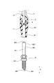
- FIGS. 3 An embodiment of an ignition coil for an internal combustion engine will be described with reference to FIGS. As shown in FIG. 3, the ignition coil 1 for an internal combustion engine is assembled with a spark plug 8 having an insulator 81 having an insulator head 82 without corrugation.
- the ignition coil 1 for an internal combustion engine holds a coil body 2 that generates a high voltage and a conductive member 3 that electrically connects the coil body 2 and the spark plug 8.
- the joint portion 4 has a plug cap 5 made of an elastic member having a cylindrical shape into which an insulator head portion 82 of the spark plug 8 is fitted.
- the plug cap 5 has a close contact portion 6 whose inner peripheral surface is in close contact with the outer peripheral surface of the insulator 81.
- the close contact portion 6 includes a distal end side close contact portion 61 that is closer to the distal end than the central position in the axial direction X, and a proximal end close contact portion 62 that is closer to the proximal end than the central position. At least a part of the proximal-side contact portion 62 has a tightening force for tightening the lever head 82 (hereinafter, also simply referred to as a tightening force) than the tightening force at any position of the distal-side contact portion 61.
- a strong strong force portion 7 is formed.
- the coil body 2 has a primary coil and a secondary coil that are magnetically coupled to each other.
- the coil main body 2 has a high-voltage tower 20 that is formed to protrude in the axial direction X.
- the high-voltage tower unit 20 holds therein a high-voltage output terminal 21 that outputs a high voltage generated in the coil body unit 2 and a resistor 22.
- the tip of the resistor 22 is in contact with the conducting member 3 in the joint portion 4.
- the joint part 4 has a cylindrical pole joint 41 and a plug cap 5 fitted to the pole joint 41 at the tip of the pole joint 41.
- a connecting seal member 11 is provided between the high-pressure tower unit 20 and the pole joint 41 to connect the two and seal between them.
- the pole joint 41 is made of an insulating resin
- the plug cap 5 is made of rubber.
- the plug cap 5 has a cylindrical shape.
- the plug cap 5 is fitted with the pole joint 41 at the base end.
- the insulator head 82 of the spark plug 8 is fitted into the plug cap 5 from the front end side.
- the spark plug 8 fitted into the plug cap 5 has an insulator 81, a housing 83 that holds the insulator 81, and an inner side of the insulator 81 so that the base end portion protrudes. It has a held terminal fitting 84 and a center electrode 85 and a ground electrode 86 for generating spark discharge.
- the terminal fitting 84 is electrically connected to the ignition coil 1 by being connected to the conduction member 3 in the joint portion 4.
- the insulator 81 is held by the housing 83 with the insulator head 82 exposed from the housing 83 to the base end side.
- the insulator head 82 has a constant outer diameter in the axial direction X.
- the outer peripheral surface of the insulator head 82 is formed straight in the axial direction X and has a shape without corrugation. As shown in FIG. 3, the spark plug 8 is fitted so that the outer peripheral surface of the insulator head 82 is in close contact with the inner peripheral surface of the contact portion 6 of the plug cap 5.
- the close contact portion 6 has a distal end side close contact portion 61 and a proximal end close contact portion 62, and the strong pressing force portion 7 is formed in the proximal end close contact portion 62.
- the strong tension force portion 7 is configured by making the thickness in the radial direction larger than that of the distal end side contact portion 61.
- the strong tightening force portion 7 is configured to have a radial thickness larger than that of the distal end side contact portion 61 by inflating the inner peripheral surface of the plug cap 5 inward.
- the close contact portion 6 is divided into the distal end side close contact portion 61 and the proximal end close contact portion 62, but this is for convenience in describing the close contact portion 6 into the distal end side portion and the proximal end side portion. It is.
- the distal end of the contact portion 6 is indicated by a symbol T and the proximal end is indicated by a symbol B.
- the strong tension portion 7 is formed such that the inner peripheral surface gently swells inward in the radial direction. That is, the strong compressive force portion 7 is formed such that the radially inner protrusion amount gradually increases toward the center in the axial direction X.
- the strong tightening force portion 7 has a length that is at least half of the length of the proximal end contact portion 62.
- the strong tightening force portion 7 is formed on the entire circumference of the inner peripheral surface of the proximal end close contact portion 62.
- the distal end side contact portion 61 has a constant inner diameter in the axial direction X, and the strong pressing force portion 7 of the proximal end side contact portion 62 has an inner diameter smaller than that of the distal end side contact portion 61. Further, the inner diameter of the contact portion 6 is smaller than the outer diameter of the lever head 82. Thereby, in the state which inserted the spark plug 8 in the plug cap 5, the contact
- the strong tension force portion 7 has a shape that bulges toward the inner peripheral side in a so-called free state in which the spark plug 8 is not inserted into the plug cap 5, but as shown in FIG. 3, In the state where the spark plug 8 is inserted, there is no swelling.
- the strong tension force portion 7 is formed on at least a part of the proximal end side contact portion 62. Therefore, it is easy to reduce the sliding frictional force when the spark plug 8 is attached to and detached from the plug cap 5. That is, when inserting the spark plug 8 into the plug cap 5, at least the center position of the contact portion 6 in the axial direction X can be inserted with a relatively weak force. Further, when removing the spark plug 8 from the plug cap 5, it can be removed by a relatively weak force at least from the central position of the contact portion 6 in the axial direction X.
- a strong force portion 7 is formed on at least a part of the proximal end side contact portion 62. For this reason, at least in the strong force portion 7, it is possible to reliably prevent a gap from being formed between the lever head 82 and to reliably prevent discharge from occurring between the lever head 82. Can do. As a result, it is possible to reliably ensure insulation between the distal end side and the proximal end side of the contact portion 6.
- the strong tension force portion 7 is configured by making the radial thickness larger than the distal end side contact portion 61. Therefore, the strong force unit 7 can be easily configured.
- the strong tension force portion 7 is configured to have a radial thickness larger than that of the distal end side contact portion 61 by expanding the inner peripheral surface of the plug cap 5 inward. Therefore, it is easy to secure the tension of the strong force unit 7.
- an ignition coil for an internal combustion engine that can ensure insulation without making it difficult to attach and detach the spark plug to the plug cap.
- This example is an example in which the insulation between the distal end side and the proximal end side of the close contact portion 6 is evaluated when the formation position of the strong tension force portion in the close contact portion 6 is variously changed in the axial direction X.
- plug caps in which the basic configuration is the same as that of the first embodiment and the formation positions of the strong tension force portions in the axial direction X are variously changed, and plug caps that do not have the strong tension force portions are provided.
- the plug cap having the strong tension force portion six plug caps were prepared in which the central position of the strong tension force portion in the axial direction X was 5 mm, 10 mm, 15 mm, 20 mm, 25 mm, and 30 mm from the tip of the contact portion 6. .
- the length of the contact portion 6 in the axial direction X was 32 mm.
- Each plug cap used was deteriorated by being left for 120 hours at a temperature of 180 ° C.
- the spark plug 8 described in the first embodiment was inserted into the ignition coil 1 provided with each plug cap 5, and the plug cap 5 and the spark plug 8 were immersed in an aqueous solution having a salt content of 5% by weight.
- a predetermined voltage was applied between the center electrode 85 and the ground electrode 86 at a frequency of 50 Hz for 20 hours.
- the presence or absence of creeping discharge was determined by checking the voltage waveform between the ignition coil and the spark plug.
- the above test was performed with various changes in applied voltage. And about the thing using the plug cap which has a strong tension part, the minimum voltage (flash over generation
- the flashover occurrence voltage when using a plug cap that does not have a strong force part was 42 kV.
- the horizontal axis is the length from the tip of the contact portion 6 to the tip of the strong force portion, and the vertical axis is the flashover occurrence voltage.
- the flashover generation voltage tends to increase as the position of the strong force portion 7 is shifted from the distal end of the contact portion 6 to the proximal end side. That is, the insulation between the distal end side and the proximal end side of the contact portion 6 tends to be improved as the position of the strong tension force portion 7 is shifted from the distal end of the contact portion 6 to the proximal end side. Further, when the position of the strong tightening force portion 7 is 10 mm or more from the distal end of the close contact portion, the flashover occurrence voltage is higher than when the strong tightening force portion is not provided.
- the ignition coil 1 having the plug cap 5 in which the strong tightening force portion 7 is formed on at least a part of the proximal end side contact portion 62 has an insulating property between the distal end side and the proximal end side of the contact portion 6. It turns out that it is excellent in.
- the strong tension force portion 7 is configured such that the outer peripheral surface of the plug cap 5 is expanded outward, so that the radial thickness is larger than that of the distal end side contact portion 61. ing. Thereby, the urging force in the strong urging force portion 7 is made stronger than the urging force of the distal end side contact portion 61.
- the outer peripheral surface of the plug cap which does not have the strong tension force part 7 is shown with the broken line.
- the strong tension portion 7 is formed such that the outer peripheral surface gently swells outward in the radial direction. That is, the strong compressive force portion 7 is formed such that the amount of outward protrusion in the radial direction gradually increases toward the center in the axial direction X.
- the strong tightening force portion 7 is formed on the entire circumference of the outer peripheral surface of the proximal end close contact portion 62.
- the inner diameter of the proximal end side contact portion 62 is the same as the inner diameter of the distal end side contact portion 61. That is, in the present embodiment, the inner diameter of the contact portion 6 is constant in the entire axial direction X.
- the radial elastic force in the strong force portion 7 can be increased by increasing the radial thickness in the strong force portion 7.
- the urging force of the strong urging force portion 7 can be increased, and insulation between the distal end side and the proximal end side of the close contact portion 6 can be ensured.
- it has the same function and effect as the first embodiment.
- the present embodiment constitutes a mounting structure 10 in which a spark plug 8 is inserted into the ignition coil 1 of the second embodiment.
- the shape of the insulator head 82 is changed with respect to the spark plug 8 described in the first embodiment. That is, the insulator head 82 has an insulator bulging portion 821 whose outer peripheral surface bulges outward.
- the insulator bulging portion 821 is formed so that the outer peripheral surface gently bulges outward.
- the insulator bulging portion 821 is formed at the same position as the position where the strong compression force portion 7 of the plug cap 5 is formed in the axial direction X in a state where the spark plug 8 is fitted into the plug cap 5 of the ignition coil 1. Yes.
- the insulator bulging portion 821 is formed on the entire circumference of the insulator 81.
- the insulator bulging portion 821 is arranged at the same position as the strong tension force portion 7 in the axial direction X. Therefore, the tightening force in the strong tightening force portion 7 can be further increased, and insulation between the distal end side and the proximal end side of the close contact portion 6 can be further ensured. In addition, it has the same function and effect as the first embodiment.
- the ignition coil (1) for the internal combustion engine of the above embodiment is assembled with a spark plug (8) having an insulator (81) having an insulator head (82) without corrugation.
- the ignition coil (1) holds a coil body (2) that generates a high voltage and a conductive member (3) that electrically connects the coil body (2) and the spark plug (8).
- the joint portion (4) has a plug cap (5) made of an elastic member having a cylindrical shape, into which the insulator head portion (82) of the spark plug (8) is fitted.
- the plug cap (5) has a contact portion (6) whose inner peripheral surface is in close contact with the outer peripheral surface of the insulator (81).
- the close contact portion (6) includes a distal end side close contact portion (61) closer to the distal end than the central position in the axial direction (X) and a proximal end close contact portion (62) closer to the proximal end than the central position. At least a part of the proximal-side contact portion (62) has a stronger tightening force than the tightening force at any position of the distal-side contact portion (61). Part (7) is formed.
- a strong tension portion is formed at least at a part of the proximal end side contact portion. Therefore, it is easy to reduce the sliding frictional force when the spark plug is attached to and detached from the plug cap. That is, when the spark plug is inserted into the plug cap, at least the center position of the contact portion in the axial direction can be inserted with a relatively weak force. Further, when removing the spark plug from the plug cap, it can be removed by a relatively weak force at least from the central position of the contact portion in the axial direction.
- the strong tightening force portion is formed in at least a part of the proximal side close contact portion, at least in the strong tightening force portion, it is possible to reliably prevent a gap from being generated between the lever head, It is possible to reliably prevent discharge from occurring between the head of the insulator. As a result, it is possible to reliably ensure insulation between the distal end side and the proximal end side of the contact portion.
- an ignition coil for an internal combustion engine that can ensure insulation without making it difficult to attach and detach the spark plug to the plug cap.
Landscapes
- Engineering & Computer Science (AREA)
- Chemical & Material Sciences (AREA)
- Combustion & Propulsion (AREA)
- Mechanical Engineering (AREA)
- General Engineering & Computer Science (AREA)
- Power Engineering (AREA)
- Ignition Installations For Internal Combustion Engines (AREA)
- Spark Plugs (AREA)
Abstract
内燃機関用の点火コイルは、コルゲーションのない碍子頭部を備えた絶縁碍子を有するスパークプラグが組み付けられる。該点火コイルは、高電圧を発生させるコイル本体部と、該コイル本体部とスパークプラグとを電気的に接続する導通部材を内部に保持したジョイント部と、を有する。該ジョイント部は、上記スパークプラグの上記碍子頭部が嵌入され、筒形状を有する弾性部材からなるプラグキャップを有する。該プラグキャップは、内周面が上記絶縁碍子の外周面に密着される密着部を有する。該密着部は、軸方向における中央位置よりも先端側の先端側密着部と、中央位置よりも基端側の基端側密着部とを有する。該基端側密着部の少なくとも一部には、上記碍子頭部を締め付ける緊迫力が、上記先端側密着部のいずれの位置における緊迫力よりも強い強緊迫力部が形成されている。
Description
本発明は、内燃機関に配設されたスパークプラグに高電圧を印加して点火させるための内燃機関用の点火コイルに関する。
内燃機関用の点火コイルとして、高電圧を発生させるコイル本体部と、該コイル本体部とスパークプラグとを電気的に接続する導通部材を内部に保持したジョイント部とを有するものがある。点火コイルのジョイント部は、エンジンヘッドのプラグホールに挿入される。そして、点火コイルの導通部材には、スパークプラグが端子金具において電気的に接続される。また、スパークプラグは、ハウジングにおいてエンジンヘッドに取り付けられる。
ここで、点火コイルのジョイント部としては、スパークプラグの絶縁碍子が嵌入される筒状のプラグキャップを有するものがある。特許文献1には、スパークプラグをプラグキャップに対して脱着し易くすべく、プラグキャップを、内周面が軸方向に凹凸状となるように形成したものが開示されている。
しかしながら、特許文献1に記載の点火コイルは、以下の問題がある。
プラグキャップの内周面が凹状に形成された部位において、絶縁碍子を締め付ける緊迫力が弱くなりやすく、かかる部位と絶縁碍子との間に微小な隙間(空気層)が形成されやすくなる。隙間が形成されてしまうと、当該隙間において放電が発生するおそれがある。さらに、プラグキャップと絶縁碍子との間の隙間に放電が繰り返し生じると、プラグキャップの内側表面が劣化(炭化)してしまう。ひいてはプラグキャップと絶縁碍子との密着面における軸方向の全体に劣化が進展すると、端子金具とハウジングとの間の絶縁性が低下するおそれがある。
プラグキャップの内周面が凹状に形成された部位において、絶縁碍子を締め付ける緊迫力が弱くなりやすく、かかる部位と絶縁碍子との間に微小な隙間(空気層)が形成されやすくなる。隙間が形成されてしまうと、当該隙間において放電が発生するおそれがある。さらに、プラグキャップと絶縁碍子との間の隙間に放電が繰り返し生じると、プラグキャップの内側表面が劣化(炭化)してしまう。ひいてはプラグキャップと絶縁碍子との密着面における軸方向の全体に劣化が進展すると、端子金具とハウジングとの間の絶縁性が低下するおそれがある。
そこで、絶縁碍子を締め付ける緊迫力を、プラグキャップ全体において強くすることにより、プラグキャップと絶縁碍子との間に隙間が形成されることを防ぎ、絶縁性を確保することも考えられる。しかしながら、プラグキャップにスパークプラグを嵌入する際や、プラグキャップからスパークプラグを取り外す際に強い力が必要となるという新たな問題が生じてしまう。
一実施形態は、スパークプラグをプラグキャップに脱着し難くすることなく、絶縁性を確保することができる内燃機関用の点火コイルを提供する。
実施形態の内燃機関用の点火コイルは、コルゲーションのない碍子頭部を備えた絶縁碍子を有するスパークプラグが組み付けられる。該点火コイルは、高電圧を発生させるコイル本体部と、該コイル本体部とスパークプラグとを電気的に接続する導通部材を内部に保持したジョイント部と、を有する。該ジョイント部は、上記スパークプラグの上記碍子頭部が嵌入され、筒形状を有する弾性部材からなるプラグキャップを有する。該プラグキャップは、内周面が上記絶縁碍子の外周面に密着される密着部を有する。該密着部は、軸方向における中央位置よりも先端側の先端側密着部と、中央位置よりも基端側の基端側密着部とを有する。該基端側密着部の少なくとも一部には、上記碍子頭部を締め付ける緊迫力が、上記先端側密着部のいずれの位置における緊迫力よりも強い強緊迫力部が形成されている。
以下、内燃機関用の点火コイルにおけるスパークプラグを嵌入する側を先端側とし、その反対側を基端側として説明する。
(第1実施形態)
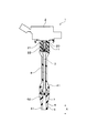
内燃機関用の点火コイルの実施形態につき、図1~図4を用いて説明する。
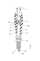
内燃機関用の点火コイル1は、図3に示すごとく、コルゲーションのない碍子頭部82を備えた絶縁碍子81を有するスパークプラグ8が組み付けられるものである。
内燃機関用の点火コイルの実施形態につき、図1~図4を用いて説明する。
内燃機関用の点火コイル1は、図3に示すごとく、コルゲーションのない碍子頭部82を備えた絶縁碍子81を有するスパークプラグ8が組み付けられるものである。
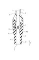
内燃機関用の点火コイル1は図1~図3に示すごとく、高電圧を発生させるコイル本体部2と、コイル本体部2とスパークプラグ8とを電気的に接続する導通部材3を内部に保持したジョイント部4と、を有する。図3に示すごとく、ジョイント部4は、スパークプラグ8の碍子頭部82が嵌入され、筒形状を有する弾性部材からなるプラグキャップ5を有する。図2に示すごとく、プラグキャップ5は、内周面が絶縁碍子81の外周面に密着される密着部6を有する。密着部6は、軸方向Xにおける中央位置よりも先端側の先端側密着部61と、中央位置よりも基端側の基端側密着部62とを有する。基端側密着部62の少なくとも一部には、碍子頭部82を締め付ける緊迫力(以下において、単に緊迫力ということもある。)が、先端側密着部61のいずれの位置における緊迫力よりも強い強緊迫力部7が形成されている。
コイル本体部2は、互いに磁気的に結合された一次コイル及び二次コイルを有する。図1に示すごとく、コイル本体部2は、軸方向Xに向って突出形成された高圧タワー部20を有する。高圧タワー部20は、コイル本体部2において発生させた高電圧を出力する高圧出力端子21及び抵抗体22を内部に保持している。抵抗体22は、先端が、ジョイント部4内の導通部材3に当接している。
ジョイント部4は、筒状のポールジョイント41と、ポールジョイント41の先端部においてポールジョイント41に嵌合されたプラグキャップ5とを有する。高圧タワー部20とポールジョイント41との間には、両者を連結すると共に両者の間をシールする連結シール部材11が設けられている。例えば、ポールジョイント41は絶縁性を有する樹脂によって構成され、プラグキャップ5はゴムによって構成される。
図1、図2に示すごとく、プラグキャップ5は、筒形状を有する。プラグキャップ5は、基端部がポールジョイント41と嵌合している。図3に示すごとく、プラグキャップ5の内側に、先端側からスパークプラグ8の碍子頭部82が嵌入される。
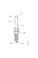
図3、図4に示すごとく、プラグキャップ5に嵌入されるスパークプラグ8は、絶縁碍子81と、絶縁碍子81を保持するハウジング83と、基端部が突出するように絶縁碍子81の内側に保持された端子金具84と、火花放電を発生させるための中心電極85及び接地電極86とを有する。端子金具84は、ジョイント部4内の導通部材3に接続されることにより、点火コイル1に電気的に接続される。絶縁碍子81は、碍子頭部82をハウジング83から基端側に露出させてハウジング83に保持されている。碍子頭部82は、軸方向Xにおいて一定の外径を有する。すなわち、碍子頭部82の外周面は、軸方向Xに真っ直ぐ形成されており、コルゲーションがない形状を有している。図3に示すごとく、スパークプラグ8は、碍子頭部82の外周面がプラグキャップ5の密着部6の内周面に密着するように嵌入される。
図2に示すごとく、密着部6は、先端側密着部61と基端側密着部62とを有し、基端側密着部62に強緊迫力部7が形成されている。強緊迫力部7は、径方向の厚みを先端側密着部61よりも大きくすることにより構成されている。本実施形態において、強緊迫力部7は、プラグキャップ5の内周面を内側に膨らませることにより、径方向の厚みを先端側密着部61よりも大きくするように構成されている。なお、密着部6を先端側密着部61と基端側密着部62とに分けたが、これは密着部6を先端側部位と基端側部位とに分けて説明するための便宜的なものである。また、便宜上、図2には、密着部6の先端を符号T、基端を符号Bにて示している。
図2に示すごとく、強緊迫力部7は、内周面が、径方向の内側に緩やかに膨らむように形成されている。すなわち、強緊迫力部7は、軸方向Xにおける中央に向かうにつれて徐々に径方向の内側の突出量が増えるように形成されている。軸方向Xにおいて、強緊迫力部7は、基端側密着部62の長さの半分以上の長さを有する。強緊迫力部7は、基端側密着部62の内周面の全周に形成されている。
先端側密着部61は軸方向Xにおいて一定の内径を有し、基端側密着部62の強緊迫力部7は先端側密着部61よりも小さい内径を有する。また、密着部6の内径は、碍子頭部82の外径よりも小さい。これにより、プラグキャップ5にスパークプラグ8を嵌入した状態において、密着部6が、碍子頭部82に密着すると共に、碍子頭部82を緊迫する。そして、強緊迫力部7においては、先端側密着部61よりも、緊迫力が強くなる。
なお、強緊迫力部7は、図2に示すごとく、プラグキャップ5にスパークプラグ8を嵌入していない、いわゆる自由状態において、内周側へ膨らんだ形状を有するが、図3に示すごとく、スパークプラグ8を嵌入した状態においては、その膨らみはない。
なお、強緊迫力部7は、図2に示すごとく、プラグキャップ5にスパークプラグ8を嵌入していない、いわゆる自由状態において、内周側へ膨らんだ形状を有するが、図3に示すごとく、スパークプラグ8を嵌入した状態においては、その膨らみはない。
次に、上記実施形態の作用効果につき説明する。
内燃機関用の点火コイル1においては、基端側密着部62の少なくとも一部に強緊迫力部7が形成されている。それゆえ、プラグキャップ5に対してスパークプラグ8を脱着するときの摺動摩擦力を低減しやすい。すなわち、スパークプラグ8をプラグキャップ5に嵌入する際は、少なくとも軸方向Xにおける密着部6の中央位置までは、比較的弱い力によって嵌入することができる。また、スパークプラグ8をプラグキャップ5から取り外す際は、少なくとも軸方向Xにおける密着部6の中央位置からは、比較的弱い力によって取り外すことができる。
内燃機関用の点火コイル1においては、基端側密着部62の少なくとも一部に強緊迫力部7が形成されている。それゆえ、プラグキャップ5に対してスパークプラグ8を脱着するときの摺動摩擦力を低減しやすい。すなわち、スパークプラグ8をプラグキャップ5に嵌入する際は、少なくとも軸方向Xにおける密着部6の中央位置までは、比較的弱い力によって嵌入することができる。また、スパークプラグ8をプラグキャップ5から取り外す際は、少なくとも軸方向Xにおける密着部6の中央位置からは、比較的弱い力によって取り外すことができる。
また、基端側密着部62の少なくとも一部に強緊迫力部7が形成されている。このため、少なくとも強緊迫力部7においては、碍子頭部82との間に隙間が生じることを確実に防ぐことができ、碍子頭部82との間に放電が発生することを確実に防ぐことができる。その結果、密着部6の先端側と基端側との間の絶縁性を確実に確保することができる。
また、強緊迫力部7は、径方向の厚みを先端側密着部61よりも大きくすることにより構成されている。それゆえ、容易に強緊迫力部7を構成することができる。
また、強緊迫力部7は、プラグキャップ5の内周面を内側に膨らませることにより、径方向の厚みを先端側密着部61よりも大きくするように構成されている。それゆえ、強緊迫力部7の緊迫力を確保しやすい。
以上のごとく、本実施形態によれば、スパークプラグをプラグキャップに脱着し難くすることなく、絶縁性を確保することができる内燃機関用の点火コイルを提供することができる。
(実験例)
本例は、密着部6における強緊迫力部の形成位置を、軸方向Xに種々変更したときの、密着部6の先端側と基端側との間の絶縁性を評価した例である。
本例は、密着部6における強緊迫力部の形成位置を、軸方向Xに種々変更したときの、密着部6の先端側と基端側との間の絶縁性を評価した例である。
本例においては、基本構成を第1実施形態と同様としつつ、軸方向Xにおける強緊迫力部の形成位置を種々変更した6つのプラグキャップと、強緊迫力部を有さないプラグキャップとを用意した。強緊迫力部を有するプラグキャップについては、軸方向Xにおける強緊迫力部の中央位置を、密着部6の先端から5mm、10mm、15mm、20mm、25mm、30mmとした6つのプラグキャップを用意した。各プラグキャップは、軸方向Xにおける密着部6の長さをいずれも32mmとした。また、各プラグキャップは、温度180℃において120時間放置して劣化させたものを用いた。
そして、各プラグキャップ5を備える点火コイル1に、第1実施形態に記載したスパークプラグ8を嵌入し、プラグキャップ5及びスパークプラグ8を、塩分5重量%の水溶液に浸漬させた。この状態において、中心電極85と接地電極86との間に、周波数50Hzにて所定の電圧を20時間印加した。その間に、密着部6の先端側と基端側との間に沿面放電が発生するか否かを観測した。沿面放電の有無は、点火コイルとスパークプラグとの間の電圧波形を確認することによって判断した。
上述の試験を、印加電圧を種々変更して行った。そして、強緊迫力部を有するプラグキャップを用いたものについて、沿面放電が生じた最小の電圧(フラッシュオーバー発生電圧)を、図5のグラフにプロットし、その近似曲線を示した。また、強緊迫力部を有さないプラグキャップを用いた場合のフラッシュオーバー発生電圧は42kVであった。図5のグラフにおいて、横軸は密着部6の先端から強緊迫力部の先端までの長さであり、縦軸はフラッシュオーバー発生電圧である。
図5から分かるように、強緊迫力部7の位置を密着部6の先端から基端側にするほど、フラッシュオーバー発生電圧が上昇する傾向にある。すなわち、強緊迫力部7の位置を、密着部6の先端から基端側にするほど、密着部6の先端側と基端側との間の絶縁性が向上する傾向にある。また、強緊迫力部7の位置が、密着部の先端から10mm以上基端側であるものは、強緊迫力部を有さない場合と比べてフラッシュオーバー発生電圧が高い。そして、強緊迫力部7の位置が密着部6の先端から15mm以上基端側であるものは、フラッシュオーバー発生電圧が充分に高い。よって、強緊迫力部7の位置を軸方向Xにおける密着部6の中央位置(密着部6の先端から16mmの位置)よりも基端側にすれば、フラッシュオーバー発生電圧を充分に高くすることができる。
この結果から、基端側密着部62の少なくとも一部に強緊迫力部7が形成されたプラグキャップ5を有する点火コイル1は、密着部6の先端側と基端側との間の絶縁性に優れていることが分かる。
この結果から、基端側密着部62の少なくとも一部に強緊迫力部7が形成されたプラグキャップ5を有する点火コイル1は、密着部6の先端側と基端側との間の絶縁性に優れていることが分かる。
(第2実施形態)
本実施形態は、図6に示すごとく、強緊迫力部7が、プラグキャップ5の外周面を外側に膨らませることにより、径方向の厚みを先端側密着部61よりも大きくするように構成されている。これにより、強緊迫力部7における緊迫力を、先端側密着部61の緊迫力よりも強くしている。なお、図6においては、強緊迫力部7を有していないプラグキャップの外周面を破線にて示している。
本実施形態は、図6に示すごとく、強緊迫力部7が、プラグキャップ5の外周面を外側に膨らませることにより、径方向の厚みを先端側密着部61よりも大きくするように構成されている。これにより、強緊迫力部7における緊迫力を、先端側密着部61の緊迫力よりも強くしている。なお、図6においては、強緊迫力部7を有していないプラグキャップの外周面を破線にて示している。
強緊迫力部7は、外周面が、径方向の外側に緩やかに膨らむように形成されている。すなわち、強緊迫力部7は、軸方向Xにおける中央に向かうにつれて徐々に径方向の外側の突出量が増えるように形成されている。強緊迫力部7は、基端側密着部62の外周面の全周に形成されている。本実施形態において、基端側密着部62の内径は、先端側密着部61の内径と同じである。すなわち、本実施形態においては、密着部6の内径は軸方向Xの全体において一定である。
その他の構成は、第1実施形態と同様である。なお、本実施形態又は本実施形態に関する図面において用いた符号のうち、第1実施形態において用いた符号と同一のものは、特に示さない限り、第1実施形態と同様の構成要素等を表す。
本実施形態においては、強緊迫力部7における径方向の厚みを増やすことができることにより、強緊迫力部7における径方向の弾性力を強くすることができる。これにより、強緊迫力部7の緊迫力を強くすることができ、密着部6の先端側と基端側との間の絶縁性を確保することができる。
その他、第1実施形態と同様の作用効果を有する。
その他、第1実施形態と同様の作用効果を有する。
(第3実施形態)
本実施形態は、図7、図8に示すごとく、第2実施形態の点火コイル1に、スパークプラグ8を嵌入した取付構造10を構成する。また、第1実施形態において説明したスパークプラグ8に対して、碍子頭部82の形状を変更している。すなわち、碍子頭部82は、外周面が外側に膨らんだ碍子膨出部821を有する。碍子膨出部821は、外周面が外側に緩やかに膨らむように形成されている。碍子膨出部821は、スパークプラグ8が点火コイル1のプラグキャップ5に嵌入された状態において、軸方向Xにおけるプラグキャップ5の強緊迫力部7が形成された位置と同じ位置に形成されている。碍子膨出部821は、絶縁碍子81の全周に形成されている。
本実施形態は、図7、図8に示すごとく、第2実施形態の点火コイル1に、スパークプラグ8を嵌入した取付構造10を構成する。また、第1実施形態において説明したスパークプラグ8に対して、碍子頭部82の形状を変更している。すなわち、碍子頭部82は、外周面が外側に膨らんだ碍子膨出部821を有する。碍子膨出部821は、外周面が外側に緩やかに膨らむように形成されている。碍子膨出部821は、スパークプラグ8が点火コイル1のプラグキャップ5に嵌入された状態において、軸方向Xにおけるプラグキャップ5の強緊迫力部7が形成された位置と同じ位置に形成されている。碍子膨出部821は、絶縁碍子81の全周に形成されている。
その他の構成は、第2実施形態と同様である。なお、本実施形態又は本実施形態に関する図面において用いた符号のうち、第2実施形態において用いた符号と同一のものは、特に示さない限り、第2実施形態と同様の構成要素等を表す。
本実施形態においては、スパークプラグ8を点火コイル1のプラグキャップ5に嵌入した状態において、軸方向Xにおける強緊迫力部7と同位置に碍子膨出部821が配される。それゆえ、強緊迫力部7における緊迫力をさらに強くすることができ、密着部6の先端側と基端側との間の絶縁性を一層確保することができる。
その他、第1実施形態と同様の作用効果を有する。
その他、第1実施形態と同様の作用効果を有する。
上記実施形態の内燃機関用の点火コイル(1)は、コルゲーションのない碍子頭部(82)を備えた絶縁碍子(81)を有するスパークプラグ(8)が組み付けられる。該点火コイル(1)は、高電圧を発生させるコイル本体部(2)と、該コイル本体部(2)とスパークプラグ(8)とを電気的に接続する導通部材(3)を内部に保持したジョイント部(4)と、を有する。該ジョイント部(4)は、上記スパークプラグ(8)の上記碍子頭部(82)が嵌入され、筒形状を有する弾性部材からなるプラグキャップ(5)を有する。該プラグキャップ(5)は、内周面が上記絶縁碍子(81)の外周面に密着される密着部(6)を有する。該密着部(6)は、軸方向(X)における中央位置よりも先端側の先端側密着部(61)と、中央位置よりも基端側の基端側密着部(62)とを有する。該基端側密着部(62)の少なくとも一部には、上記碍子頭部(82)を締め付ける緊迫力が、上記先端側密着部(61)のいずれの位置における緊迫力よりも強い強緊迫力部(7)が形成されている。
上記内燃機関用の点火コイルにおいては、基端側密着部の少なくとも一部に強緊迫力部が形成されている。それゆえ、プラグキャップに対してスパークプラグを脱着するときの摺動摩擦力を低減しやすい。すなわち、スパークプラグをプラグキャップに嵌入する際は、少なくとも軸方向における密着部の中央位置までは、比較的弱い力によって嵌入することができる。また、スパークプラグをプラグキャップから取り外す際は、少なくとも軸方向における密着部の中央位置からは、比較的弱い力によって取り外すことができる。
また、基端側密着部の少なくとも一部に強緊迫力部が形成されているため、少なくとも強緊迫力部においては、碍子頭部との間に隙間が生じることを確実に防ぐことができ、碍子頭部との間に放電が発生することを確実に防ぐことができる。その結果、密着部の先端側と基端側との間の絶縁性を確実に確保することができる。
以上のごとく、上記実施形態によれば、スパークプラグをプラグキャップに脱着し難くすることなく、絶縁性を確保することができる内燃機関用の点火コイルを提供することができる。
1 点火コイル
2 コイル本体部
3 導通部材
4 ジョイント部
5 プラグキャップ
6 密着部
61 先端側密着部
62 基端側密着部
7 強緊迫力部
8 スパークプラグ
81 絶縁碍子
82 碍子頭部
X 軸方向
2 コイル本体部
3 導通部材
4 ジョイント部
5 プラグキャップ
6 密着部
61 先端側密着部
62 基端側密着部
7 強緊迫力部
8 スパークプラグ
81 絶縁碍子
82 碍子頭部
X 軸方向
Claims (3)
- コルゲーションのない碍子頭部(82)を備えた絶縁碍子(81)を有するスパークプラグ(8)が組み付けられる、内燃機関用の点火コイル(1)であって、
該内燃機関用の点火コイル(1)は、高電圧を発生させるコイル本体部(2)と、該コイル本体部(2)とスパークプラグ(8)とを電気的に接続する導通部材(3)を内部に保持したジョイント部(4)と、を有し、
該ジョイント部(4)は、上記スパークプラグ(8)の上記碍子頭部(82)が嵌入され、筒形状を有する弾性部材からなるプラグキャップ(5)を有し、
該プラグキャップ(5)は、内周面が上記絶縁碍子(81)の外周面に密着される密着部(6)を有し、
該密着部(6)は、軸方向(X)における中央位置よりも先端側の先端側密着部(61)と、中央位置よりも基端側の基端側密着部(62)とを有し、
該基端側密着部(62)の少なくとも一部には、上記碍子頭部(82)を締め付ける緊迫力が、上記先端側密着部(61)のいずれの位置における緊迫力よりも強い強緊迫力部(7)が形成されていることを特徴とする内燃機関用の点火コイル(1)。 - 上記強緊迫力部(7)は、径方向の厚みを上記先端側密着部(61)よりも大きくすることにより構成されていることを特徴とする請求項1に記載の内燃機関用の点火コイル(1)。
- 上記強緊迫力部(7)は、上記プラグキャップ(5)の内周面を内側に膨らませることにより、径方向の厚みを上記先端側密着部(61)よりも大きくするように構成されていることを特徴とする請求項2に記載の内燃機関用の点火コイル(1)。
Priority Applications (1)
| Application Number | Priority Date | Filing Date | Title |
|---|---|---|---|
| US15/564,876 US10305258B2 (en) | 2015-04-08 | 2016-04-07 | Ignition coil for internal combustion engine |
Applications Claiming Priority (2)
| Application Number | Priority Date | Filing Date | Title |
|---|---|---|---|
| JP2015079346A JP6477184B2 (ja) | 2015-04-08 | 2015-04-08 | 内燃機関用の点火コイル |
| JP2015-079346 | 2015-04-08 |
Publications (1)
| Publication Number | Publication Date |
|---|---|
| WO2016163438A1 true WO2016163438A1 (ja) | 2016-10-13 |
Family
ID=57072588
Family Applications (1)
| Application Number | Title | Priority Date | Filing Date |
|---|---|---|---|
| PCT/JP2016/061349 Ceased WO2016163438A1 (ja) | 2015-04-08 | 2016-04-07 | 内燃機関用の点火コイル |
Country Status (3)
| Country | Link |
|---|---|
| US (1) | US10305258B2 (ja) |
| JP (1) | JP6477184B2 (ja) |
| WO (1) | WO2016163438A1 (ja) |
Families Citing this family (2)
| Publication number | Priority date | Publication date | Assignee | Title |
|---|---|---|---|---|
| KR101987545B1 (ko) * | 2017-10-19 | 2019-06-10 | 덴소코리아오토모티브 주식회사 | 폴조인트 일체형 고무조인트 제조방법 |
| JP7413883B2 (ja) * | 2020-03-27 | 2024-01-16 | 株式会社デンソー | プラグキャップ及びこれを備えた点火コイル |
Citations (3)
| Publication number | Priority date | Publication date | Assignee | Title |
|---|---|---|---|---|
| JPH11230015A (ja) * | 1998-02-16 | 1999-08-24 | Toyota Motor Corp | 内燃機関用点火コイル |
| JP2008021870A (ja) * | 2006-07-13 | 2008-01-31 | Denso Corp | 点火コイル |
| JP2014022183A (ja) * | 2012-07-18 | 2014-02-03 | Denso Corp | 内燃機関用のスパークプラグ及びこれを備えた点火装置 |
Family Cites Families (8)
| Publication number | Priority date | Publication date | Assignee | Title |
|---|---|---|---|---|
| JPH08284789A (ja) * | 1995-04-13 | 1996-10-29 | Mitsubishi Electric Corp | 内燃機関の点火装置用伝送装置 |
| JPH09180856A (ja) * | 1995-12-26 | 1997-07-11 | Ngk Spark Plug Co Ltd | 内燃機関用スパークプラグとプラグコードのプラグキ ャップ |
| US5716223A (en) * | 1996-02-29 | 1998-02-10 | General Motors Corporation | Spark plug boot insulator |
| US6358071B1 (en) * | 2000-08-10 | 2002-03-19 | Delphi Technologies, Inc. | Electrical connection for a spark plug and method of assembling the same |
| JP3996122B2 (ja) | 2003-12-26 | 2007-10-24 | 阪神エレクトリック株式会社 | 内燃機関用点火コイル |
| US7441553B2 (en) * | 2006-06-01 | 2008-10-28 | Denso Corporation | Ignition coil, mounting structure, and method for mounting of the same |
| JP2007321666A (ja) * | 2006-06-01 | 2007-12-13 | Denso Corp | 点火コイル |
| FR2923093A1 (fr) * | 2007-10-29 | 2009-05-01 | Continental Automotive France | Dispositif d'allumage par etincelle a capteur de combustion integre |
-
2015
- 2015-04-08 JP JP2015079346A patent/JP6477184B2/ja not_active Expired - Fee Related
-
2016
- 2016-04-07 US US15/564,876 patent/US10305258B2/en active Active
- 2016-04-07 WO PCT/JP2016/061349 patent/WO2016163438A1/ja not_active Ceased
Patent Citations (3)
| Publication number | Priority date | Publication date | Assignee | Title |
|---|---|---|---|---|
| JPH11230015A (ja) * | 1998-02-16 | 1999-08-24 | Toyota Motor Corp | 内燃機関用点火コイル |
| JP2008021870A (ja) * | 2006-07-13 | 2008-01-31 | Denso Corp | 点火コイル |
| JP2014022183A (ja) * | 2012-07-18 | 2014-02-03 | Denso Corp | 内燃機関用のスパークプラグ及びこれを備えた点火装置 |
Also Published As
| Publication number | Publication date |
|---|---|
| US10305258B2 (en) | 2019-05-28 |
| US20180109079A1 (en) | 2018-04-19 |
| JP6477184B2 (ja) | 2019-03-06 |
| JP2016201213A (ja) | 2016-12-01 |
Similar Documents
| Publication | Publication Date | Title |
|---|---|---|
| JP4267042B2 (ja) | 内燃機関用点火コイル装置 | |
| JP5719419B2 (ja) | 点火プラグ及びその製造方法 | |
| US10107252B2 (en) | Ignition plug and ignition device | |
| JP6477184B2 (ja) | 内燃機関用の点火コイル | |
| JP2017027978A (ja) | 内燃機関用の点火コイル | |
| WO2011118087A1 (ja) | スパークプラグ | |
| JP5888160B2 (ja) | 内燃機関用のスパークプラグ及びこれを備えた点火装置 | |
| JP6669185B2 (ja) | 内燃機関用のスパークプラグ及びこれを備えた点火装置 | |
| JP2016092206A (ja) | 内燃機関用点火コイル | |
| JP6311476B2 (ja) | 点火プラグ | |
| JP2013131375A (ja) | 点火プラグ | |
| JP2014056653A (ja) | スパークプラグ | |
| JP5642129B2 (ja) | スパークプラグ | |
| JP6476766B2 (ja) | 内燃機関用の点火コイル及びその取付構造 | |
| JP2012007595A (ja) | 内燃機関用点火コイル | |
| JP2016201213A5 (ja) | ||
| JP6592473B2 (ja) | 点火プラグ | |
| JP2017022286A (ja) | 内燃機関用の点火コイル | |
| US10340666B2 (en) | Spark plug | |
| JP6333135B2 (ja) | スパークプラグ | |
| JP7070196B2 (ja) | 内燃機関用のスパークプラグ | |
| JP5721680B2 (ja) | スパークプラグ | |
| JP2021050674A (ja) | 内燃機関用点火コイルおよび製造方法 | |
| CN106981823B (zh) | 火花塞 | |
| US10790640B2 (en) | Spark plug for internal combustion engine |
Legal Events
| Date | Code | Title | Description |
|---|---|---|---|
| 121 | Ep: the epo has been informed by wipo that ep was designated in this application |
Ref document number: 16776604 Country of ref document: EP Kind code of ref document: A1 |
|
| WWE | Wipo information: entry into national phase |
Ref document number: 15564876 Country of ref document: US |
|
| NENP | Non-entry into the national phase |
Ref country code: DE |
|
| 122 | Ep: pct application non-entry in european phase |
Ref document number: 16776604 Country of ref document: EP Kind code of ref document: A1 |