WO2016163047A1 - 洗濯機 - Google Patents
洗濯機 Download PDFInfo
- Publication number
- WO2016163047A1 WO2016163047A1 PCT/JP2015/079980 JP2015079980W WO2016163047A1 WO 2016163047 A1 WO2016163047 A1 WO 2016163047A1 JP 2015079980 W JP2015079980 W JP 2015079980W WO 2016163047 A1 WO2016163047 A1 WO 2016163047A1
- Authority
- WO
- WIPO (PCT)
- Prior art keywords
- energization
- power supply
- clutch
- motor
- supply voltage
- Prior art date
- Legal status (The legal status is an assumption and is not a legal conclusion. Google has not performed a legal analysis and makes no representation as to the accuracy of the status listed.)
- Ceased
Links
Images






Classifications
-
- D—TEXTILES; PAPER
- D06—TREATMENT OF TEXTILES OR THE LIKE; LAUNDERING; FLEXIBLE MATERIALS NOT OTHERWISE PROVIDED FOR
- D06F—LAUNDERING, DRYING, IRONING, PRESSING OR FOLDING TEXTILE ARTICLES
- D06F37/00—Details specific to washing machines covered by groups D06F21/00 - D06F25/00
- D06F37/30—Driving arrangements
- D06F37/40—Driving arrangements for driving the receptacle and an agitator or impeller, e.g. alternatively
-
- D—TEXTILES; PAPER
- D06—TREATMENT OF TEXTILES OR THE LIKE; LAUNDERING; FLEXIBLE MATERIALS NOT OTHERWISE PROVIDED FOR
- D06F—LAUNDERING, DRYING, IRONING, PRESSING OR FOLDING TEXTILE ARTICLES
- D06F2103/00—Parameters monitored or detected for the control of domestic laundry washing machines, washer-dryers or laundry dryers
- D06F2103/44—Current or voltage
-
- D—TEXTILES; PAPER
- D06—TREATMENT OF TEXTILES OR THE LIKE; LAUNDERING; FLEXIBLE MATERIALS NOT OTHERWISE PROVIDED FOR
- D06F—LAUNDERING, DRYING, IRONING, PRESSING OR FOLDING TEXTILE ARTICLES
- D06F2105/00—Systems or parameters controlled or affected by the control systems of washing machines, washer-dryers or laundry dryers
-
- D—TEXTILES; PAPER
- D06—TREATMENT OF TEXTILES OR THE LIKE; LAUNDERING; FLEXIBLE MATERIALS NOT OTHERWISE PROVIDED FOR
- D06F—LAUNDERING, DRYING, IRONING, PRESSING OR FOLDING TEXTILE ARTICLES
- D06F23/00—Washing machines with receptacles, e.g. perforated, having a rotary movement, e.g. oscillatory movement, the receptacle serving both for washing and for centrifugally separating water from the laundry
- D06F23/04—Washing machines with receptacles, e.g. perforated, having a rotary movement, e.g. oscillatory movement, the receptacle serving both for washing and for centrifugally separating water from the laundry and rotating or oscillating about a vertical axis
-
- D—TEXTILES; PAPER
- D06—TREATMENT OF TEXTILES OR THE LIKE; LAUNDERING; FLEXIBLE MATERIALS NOT OTHERWISE PROVIDED FOR
- D06F—LAUNDERING, DRYING, IRONING, PRESSING OR FOLDING TEXTILE ARTICLES
- D06F33/00—Control of operations performed in washing machines or washer-dryers
- D06F33/30—Control of washing machines characterised by the purpose or target of the control
- D06F33/47—Responding to irregular working conditions, e.g. malfunctioning of pumps
-
- D—TEXTILES; PAPER
- D06—TREATMENT OF TEXTILES OR THE LIKE; LAUNDERING; FLEXIBLE MATERIALS NOT OTHERWISE PROVIDED FOR
- D06F—LAUNDERING, DRYING, IRONING, PRESSING OR FOLDING TEXTILE ARTICLES
- D06F34/00—Details of control systems for washing machines, washer-dryers or laundry dryers
- D06F34/10—Power supply arrangements, e.g. stand-by circuits
Definitions
- the embodiment of the present invention relates to a washing machine.
- a predetermined energization pattern may be applied to the induction motor in order to assist switching of the clutch.
- the induction motor is easily affected by fluctuations in the power supply voltage, and the operation amount and operation speed of the induction motor change. Therefore, when the voltage is low, the operation amount of the induction motor becomes small and the operation speed becomes slow, so that clutch switching may not be performed normally.
- the voltage is high, the amount of operation of the induction motor is increased, and the operation speed is increased, so that a load is applied to the clutch. For example, a mechanical failure may be induced.
- the power supply voltage often fluctuates, and the necessity of considering voltage fluctuation in clutch switching has increased.
- the washing machine which concerns on embodiment rotates a pulsator and a dehydration tank using an induction motor.
- This washing machine has a first state in which the driving force from the induction motor is transmitted only to the rotating shaft of the pulsator, and a second state in which the driving force from the induction motor is transmitted to the rotating shaft of the pulsator and the rotating shaft of the dewatering tank.
- It has a clutch for switching.
- it has a voltage detection unit that detects a power supply voltage applied to the dielectric motor, and performs an auxiliary operation of switching the clutch by applying a predetermined energization pattern to the induction motor during the clutch switching operation. And an energization pattern is changed according to the level of the power supply voltage detected by the voltage detection part.
- FIG. 1 is a longitudinal side view schematically showing the overall configuration of a washing machine according to a first embodiment.
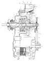
- Enlarged longitudinal sectional view of the drive mechanism at the clutch wash position Enlarged longitudinal sectional view of the drive mechanism at the clutch dewatering position
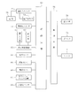
- the block diagram which shows the electric constitution of the washing machine which concerns on embodiment The figure which shows the electricity supply pattern (energization timing) to the motor of the switch auxiliary
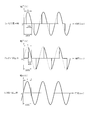
- Diagram showing voltage waveform of AC power supply The figure which shows the electricity supply pattern (energization timing) to the motor at the time of the switch auxiliary
- the energization pattern may mean, for example, energization timings shown in FIGS. 5, 7, 8, 9, and 12 described later, and for example, FIGS. 10 and 11 described later.
- FIG. 1 shows a schematic configuration of the washing machine 1.
- a water tank 3 for receiving water during dehydration or the like is provided via an elastic suspension mechanism 4.
- the rotating tank 5 as a washing tank and a dehydration tank in which the laundry is accommodated in the inside is rotatably provided, and the bottom part in the rotating tank 5 is used for water flow generation.
- the stirring body (pulsator) 6 is provided.
- the motor 7 is constituted by an induction motor. The configuration of the drive mechanism unit 9 will be described later.
- the motor 7, the belt transmission mechanism 8, and the drive mechanism unit 9 cause the stirring body 6 to rotate forward and backward in a detergent washing and rinsing operation, thereby generating a stirring water flow in the rotating tank 5.
- the rotary tank 5 is rotated integrally with the stirring body 6 at a high speed.
- the drain valve 71 etc. for draining from the said rotating tank 5 etc. are provided in the bottom part of the said water tank 3 (refer FIG. 4).
- a balance ring 10 is attached to the upper end portion of the rotary tub 5 and a dewatering hole 11 is provided for draining the rotary tub 5 during dehydration through the balance ring 10. ing.
- a bowl cover 12 having a substantially ring shape is provided at the upper end of the water tank 3.
- a plastic top cover 13 is provided at the upper end of the outer box 2.
- the top cover 13 has a substantially circular laundry entrance at the center, and is provided with a double-fold type lid 14 for opening and closing the laundry entrance.
- a water supply mechanism having a water supply valve or the like is provided on the rear side of the top cover 13, and an operation input unit (operation panel) 61 or the like is provided on the front side of the top cover 13.
- a control device 60 that mainly controls the washing machine 1 is provided (see FIG. 4).
- FIG. 2 shows a state where the clutch 15 is in the washing position (the raised position)
- FIG. 3 shows a state where the clutch 15 is in the dewatering position (the lowered position).
- a bearing housing 16 is attached to the outer bottom of the water tank 3.
- the bearing housing 16 is configured by connecting an upper frame 17 and a lower frame 18 at an outer peripheral side portion.
- a cylindrical portion 17 a that protrudes upward is formed at the center of the upper frame 17, and a cylindrical portion 18 a that protrudes downward is formed at the center of the lower frame 18.
- a bearing 19 made of a ball bearing is fitted and fixed, and a hollow (circular tubular) upper tank shaft 20 is provided supported by the bearing 19.
- a flange portion 20a is integrally provided at the upper end portion of the upper tank shaft 20, and the rotating tank 5 is fixed to the flange portion 20a.
- An upper stirring shaft 21 is inserted into the hollow portion of the upper tank shaft 20 so as to penetrate vertically. At this time, the upper stirring shaft 21 is rotatably supported via bearing metals 22 and 23. The upper end of the upper stirring shaft 21 is connected to the stirring body 6.
- a seal member 24 is provided between the inner peripheral surface of the upper end of the cylindrical portion 17 a and the outer peripheral surface of the upper tank shaft 20.
- a bearing 25 made of a ball bearing is fitted and fixed in the cylindrical portion 18 a of the lower frame 18, and a hollow (circular tubular) lower tank shaft 26 is provided supported by the bearing 25.
- a lower stirring shaft 27 is vertically supported and rotatably supported through bearing metals 28 and 29.
- a driven pulley 30 is attached to the lower end portion of the lower stirring shaft 27, and a boss portion 31 is fixedly positioned on the upper surface portion of the driven pulley 30. Thereby, the boss portion 31 rotates integrally with the lower stirring shaft 27.
- the motor 7 is provided downward on the lower surface side of the upper frame 17, and a drive pulley 32 is attached to the output shaft 7a.
- a V-belt 33 is stretched between the driving pulley 32 and the driven pulley 30.
- the upper tank shaft 20 and the lower tank shaft 26 are connected by a gear case 34, and the upper stirring shaft 21 and the lower stirring shaft 27 are constituted by a planetary gear device disposed in the gear case 34. It is connected via a reduction gear mechanism 35.
- the gear case 34 has a large cylindrical shape with an open bottom surface, and integrally includes a protruding cylindrical portion 34a having a small diameter on the upper surface portion.
- the protruding cylindrical portion 34 a is connected to the lower end portion of the upper tank shaft 20.
- a flange-like portion 26a that extends in the outer peripheral direction is integrally provided at the upper end portion of the lower tank shaft 26, and the flange-like portion 26a closes the lower surface of the gear case 34 so that the gear case 34 It is connected to the lower end.
- the reduction gear mechanism 35 includes an external gear 36 provided at the upper end of the lower stirring shaft 27, an internal gear 37 provided on the inner peripheral surface portion of the gear case 34, and between the external gear 36 and the internal gear 37.
- a plurality of (for example, three) planetary gears 38 provided, and a carrier 39 provided so as to connect shaft portions of the plurality of planetary gears 38 are provided.
- the center portion of the carrier 39 is connected to the lower end portion of the upper stirring shaft 21.
- the clutch 15 for connecting and disconnecting the lower tank shaft 26 and the lower stirring shaft 27 (boss part 31) is provided on the lower outer peripheral portion of the lower tank shaft 26. Further, an elevating mechanism 40 as a clutch switching means for moving the clutch 15 up and down and switching its state is provided on the lower surface portion of the lower frame 18, and a co-rotation preventing portion 41 is provided.
- the clutch 15 has a substantially cylindrical shape as a whole.
- a circular hook-shaped (flange-shaped) engaged portion 42 is integrally formed at the upper end portion of the clutch 15.
- the engaged portion 42 is formed with a plurality of (for example, twelve) tooth portions 42a that are located on the outer peripheral portion of the upper surface and are arranged in the circumferential direction.
- the clutch 15 has an inner serration portion 43 extending in the vertical direction on the entire inner peripheral surface thereof.
- the lower half of the lower tank shaft 26 (the part protruding downward from the bearing 25) has an upper and lower portion corresponding to the inner serration portion 43.
- a serration portion 44 extending in the direction is formed.
- the clutch 15 is fitted into the outer periphery of the lower end of the lower tank shaft 26 so that the inner serration portion 43 is always engaged with the serration portion 44 so as to move up and down and rotate integrally in the circumferential direction. Yes.
- a coil spring 45 is disposed at the outer peripheral portion of the lower tank shaft 26, and the clutch 15 is always biased toward the lowered position (dehydration position). Has been.
- a plurality of, for example, four fitting recesses 15a and fitting projections 15b that are fitted to the boss portion 31 are alternately provided in the circumferential direction.
- teeth 46 and recesses 47 into which the fitting recesses 15a and the fitting projections 15b are fitted are alternately provided on the upper surface of the boss 31 in the circumferential direction.
- the co-rotation preventing portion 41 is located on the outer peripheral portion of the cylindrical portion 18a and has an engaging portion 48 (concave portion) with which an engaged portion 42 (tooth portion 42a) at the upper end of the clutch 15 is engaged. ing.
- the elevating mechanism 40 includes a clutch lever 49 that moves the clutch 15 up and down, an operation lever 50 that swings the clutch lever 49, and the like.
- the clutch lever 49 is supported by a support portion 41a provided integrally with the co-rotation prevention portion 41 so that an intermediate portion thereof is swingable in the vertical direction, and a front end portion of the engaged portion 42 of the clutch 15 is supported.
- a contact portion (not shown) for engaging and pushing up on the lower surface side is provided.
- a tension coil spring 51 is disposed between the base end portion side of the clutch lever 49 and the support portion 41a, and the locking operation portion 49a of the base end portion of the clutch lever 49 is provided. Is always locked to the operation lever 50.
- the operation lever 50 is supported on the lower frame 18 by a pin 52 so as to be rotatable in the horizontal direction, and has an inclined locking portion 50a to which the locking operation portion 49a is locked. is doing. As a result, the base end portion of the clutch lever 49 is moved in the vertical direction as the operation lever 50 rotates in the horizontal direction.
- the operation lever 50 is driven by the drain valve motor in conjunction with opening and closing of the drain valve.
- a clutch position detection sensor (not shown) for detecting the position of the clutch 15 is provided in the co-rotation preventing portion 41.
- the lifting mechanism 40 configured as described above functions as clutch switching means together with the drain valve motor.
- the drain valve is closed during the washing process and the rinsing process.
- the elevating mechanism 40 has the operation lever 50 in the state shown in FIG. 2 and pushes down the base end portion of the clutch lever 49, and the contact portion at the tip end of the clutch lever 49 causes the clutch 15 to move to the coil spring 45.
- the spring is pushed up against the spring force and positioned at the washing position.
- the operation lever 50 is driven, and as shown in FIG. The contact portion is lowered, and the clutch 15 is lowered to the dewatering position by the spring force of the coil spring 45.
- the mechanisms such as the motor 7, the water supply valve 70, and the drain valve 71 are controlled by the control device 60.
- the control device 60 receives key operation signals from the operation input unit 61 and detection signals from the water level sensor 64, the lid switch, the clutch position detection sensor, and the like.
- the control device 60 controls each mechanism such as the motor 7, the water supply valve 70, and the drain valve 71 in accordance with a control program stored in a ROM or the like based on the key operation of the operation input unit 61 by the user and the various inputs. Control.
- the control device 60 automatically executes a washing operation roughly divided into a washing process, a rinsing process (a dehydration rinsing process and a rinsing process), and a dehydration process.
- the stirrer 6 In the washing process and the rinsing process, the stirrer 6 is alternately rotated in the forward / reverse direction at a low speed, and in the dehydration rinsing process and the dewatering process, the rotating tank 5 and the agitator 6 are integrated in one direction (forward direction) at a high speed. It is rotated.
- the control device generates a clutch switching command (rotation drive command for the drain valve motor) in accordance with the washing operation process, and the clutch 15 is set to the washing position and the dewatering position. Switching control between.
- the clutch 15 is switched to the washing position immediately before the start of the washing process and the rinsing process (timing for closing the drain valve 71), and at the end of the washing process and the rinsing process (timing for opening the drain valve 71). Then, it is switched to the dewatering position.
- the control device executes a switching auxiliary operation for rotating and stopping the motor 7 for a short time (a few seconds to 10 seconds in total) when the clutch 15 is switched (when the drain valve motor is driven).
- This auxiliary switching operation is performed by rotating the motor 7 in the forward direction and the reverse direction with a predetermined energization pattern in small increments. Accordingly, when the clutch 15 is switched to the washing position, the engagement of the engaged portion 42 of the clutch 15 with the engaging portion 48 of the joint rotation preventing portion 41 is urged, and when the clutch 15 is switched to the dewatering position, the lower end of the clutch 15 is promoted. The fitting of the part to the boss part 31 is promoted. This will be described later.
- a control device 60 constituting control means is provided at the lower part of the rear part in the outer box 1.
- FIG. 4 shows an outline of the electrical configuration centered on the control device 60.
- the control device 60 is mainly composed of a microcomputer (including a CPU, a ROM, and a RAM) and a nonvolatile memory, and has a function of controlling the overall operation of the washing machine 1.
- the control device 60 receives an operation signal from the operation input unit 61 via the display control unit 35.
- the control device 60 receives the water level detection signal of the water level sensor 64 that detects the water level of the water stored in the water tank 3, the rotation speed detection signal of the rotation sensor 65 that detects the rotation speed of the motor 7, and the current flowing through the motor 7.
- a current detection signal of the current sensor 66 to be detected, a swing detection signal of the safety lever switch device 67, a swing detection signal of the acceleration sensor 68, and the like are input.
- the control device 60 controls the display unit 62 via the display control unit 63 based on these input signals and the control program and data stored in the ROM and read out to the RAM in advance.
- the control device 60 controls the water supply valve 70, the drain valve 71, the motor 7, and the like via the drive circuit 76.
- the switching assist operation described above is performed by controlling the motor 7 by the control device 60.
- a power source 75 is connected to the control device 60 via a power on switch 72. Between the power-on switch 72 and the control device 60, a voltage detector 73 for detecting the voltage therebetween is disposed. The power supply voltage applied to the motor 7 is detected by the voltage detection unit 73. The voltage value signal of the voltage detected by the voltage detection unit 73 is transmitted to the control device 60. In the control device 60, the detected power supply voltage is compared with the reference voltage, and its level is determined. Further, a power-off switch 74 is connected to the control device 60.
- the detection of the power supply voltage by the voltage detection unit 73 can be performed between the time when the power is turned on by the power-on switch 72 of the washing machine 1 and the time when the clutch is switched.
- the power supply voltage value for example, a power supply voltage detected when the power is turned on may be used, or a power supply voltage 5 seconds after the power is turned on, for example, after a predetermined time has elapsed after the power is turned on may be used. Since it is considered that the power supply voltage is stabilized after a while after the power is turned on, this is preferable.
- the power supply voltage value a plurality of power supply voltages may be detected every time a predetermined time has elapsed after the power is turned on, and an average value of the power supply voltage values may be used. Moreover, it is good also as using the power supply voltage just before switching a clutch at the time of a driving
- the energization pattern means the energization timing shown in FIGS. 5B to 5D and FIGS. 7B to 7D.
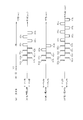
- FIG. 5 shows the energization pattern (energization timing) to the motor 7 in the switching assisting operation (first assisting operation) at the time of clutch switching when shifting from the washing process to the dehydrating process in the first embodiment.
- FIG. 5A shows the switching timing of the drain valve 71 from the closed state to the open state when switching from the washing process to the dehydration process.
- the period during which the drain valve 71 is in the closed state is a washing stroke, and at time T1, the state is switched from the closed state to the open state. After time T1, switching of the clutch 15 is started as a transition operation to the dehydration stroke.
- FIG. 5B shows an energization pattern (energization timing) when the power supply voltage detected by the voltage detection unit 73 is the reference voltage in the switching assist operation of the clutch 15.
- the energization pattern means the energization timing shown in FIG.
- the reference voltage is, for example, 220 ⁇ 20 [V]. If it exceeds this range, it will be judged as a high voltage, and if it falls below, it will be judged as a low voltage.
- the energization pattern includes energization units 80 a and 80 b and an energization unit 81 as shown in FIG.
- the motor forward rotation energization unit 80a and the motor reverse rotation energization unit 80b are set as one set, and this is repeated three times, and the motor forward rotation energization unit 81 is energized three times.
- the time length of the energization units 80a and 80b is, for example, 0.1 second, and the time length between the energization units 80a-80b is, for example, 0.7 seconds.
- the interval between the energization unit 80b and the energization unit 81 is, for example, 2.0 seconds.
- the time length of the energization unit 81 is 0.1 second, and the time length between the energization units 81 is, for example, 0.5 second.
- an AC power supply constituted by a sine wave voltage waveform as shown in FIG. 6 has, for example, a single-phase two-wire 220V and a frequency of 50 Hz.
- Energization units 80a and 80b urge the disengagement of the engaged portion 42 of the clutch 15 from the engaging portion 48 of the joint rotation preventing portion 41. Further, the energization unit 81 facilitates the fitting of the lower end portion of the clutch 15 to the boss portion 31.
- FIG. 5C shows an energization pattern (energization timing) when the power supply voltage detected by the voltage detection unit 73 is higher than the reference voltage.
- the energization pattern means the energization timing shown in FIG.
- the number of energizations is reduced by reducing the number of energization units 80a, 80b, and 81 as compared with the case where the power supply voltage is the reference voltage. That is, as shown in FIG. 5 (b), the energization pattern includes a normal motor energization unit 80a and a motor inversion energization unit 80b as one set, and this is repeated for two sets.
- the unit 81 is energized twice.
- the energization time lengths of the energization units 80a, 80b, 81 are the same as those in FIG. 5A, and the intervals between the energization units 80a, 80b, 81 are the same. In this way, even when the power supply voltage is high, the operation amount of the motor 7 and the operation speed of the motor 7 can be reduced. Thereby, since the operation amount and the operation speed of the motor 7 similar to those in the case where the reference voltage is applied can be suppressed, it is possible to suppress, for example, a mechanical failure by applying a load to the clutch.
- FIG. 5D shows an energization pattern (energization timing) corresponding to the case where the power supply voltage detected by the voltage detection unit 73 is lower than the reference voltage.
- the energization pattern means the energization timing shown in FIG.
- the number of energizations is increased by increasing the number of energization units 80a, 80b, and 81 as compared with the case where the power supply voltage is the reference voltage. That is, as shown in FIG. 5 (d), the energization timing is set by energizing unit 80a for motor normal rotation and energization unit 80b for motor reversal as one set, and this is repeated for 4 sets.
- the unit 81 is energized four times.
- the energization time lengths of the energization units 80a, 80b, 81 are the same as those in FIG. 5B, and the intervals between the energization units 80a, 80b, 81 are the same.
- the reference voltage is applied even when the operation amount of the motor 7 is small and the operation speed is slow because the power supply voltage is lower than the reference voltage, and the clutch 15 may not be switched normally. It is possible to increase the operation amount and the operation speed of the motor 7 in the same manner as in the above case. Thereby, switching of the clutch 15 is realizable reliably.
- the energization units 80a and 80b sufficiently urge the disengagement of the engaged portion 42 of the clutch 15 from the engagement portion 48 of the co-rotation prevention portion 41, and the lower end of the clutch 15 is energized by the energization unit 81.
- the fitting of the part to the boss part 31 is sufficiently promoted.
- FIG. 7 shows an energization pattern (energization timing) to the motor 7 during the switching assist operation (second assist operation) at the time of clutch switching when shifting from the dehydration stroke to the washing stroke in the first embodiment.
- FIG. 7A shows the switching timing of the drain valve 71 from the open state to the closed state when switching from the dehydration process to the washing (rinsing) process.
- the period during which the drain valve 71 is in the closed state is a washing (rinsing) process, and the time is switched from the open state to the closed state at time T2, and the switching of the clutch 15 is started as a preparation operation for the dehydration process.
- FIG. 7B shows an energization pattern (energization timing) corresponding to the case where the power supply voltage detected by the voltage detection unit 73 is the reference voltage.
- the energization pattern means the energization timing shown in FIG.
- the reference voltage is, for example, 220 ⁇ 20 [V].
- the energization pattern includes energization units 82a, 82b, 83a, and 83b.
- the motor forward rotation energization unit 82a and the motor inversion energization unit 82b are set as one set, and this is repeated for three sets. Further, the motor forward rotation energization unit 83a and the motor inversion energization unit 83b are set as one set. This is repeated for two sets and energized.
- the time length of the energization units 82a and 82b is, for example, 0.1 seconds, and the time length between the energization units 82a and 82b is, for example, 0.7 seconds.
- the time length between the energization unit 82b and the energization unit 83a is, for example, 0.7 seconds.
- the duration of the energization units 83a and 83b is 0.5 seconds, and the interval between the energization units 83a and 83b is, for example, 0.7 seconds.
- an AC power source composed of a sine wave as shown in FIG. 6 has, for example, a single-phase two-wire 220V and a frequency of 50 Hz.
- Energization units 82 a and 82 b urge the engagement of the engaged portion 42 of the clutch 15 to be disengaged from the engaging portion 48 of the joint rotation preventing portion 41. Further, the energization units 83a and 83b prompt the fitting of the lower end portion of the clutch 15 to the boss portion 31.
- FIG. 7C shows an energization pattern (energization timing) corresponding to the case where the power supply voltage detected by the voltage detector 73 is higher than the reference voltage.
- the energization pattern means the energization timing shown in FIG.
- the number of energizations is reduced by reducing the number of energization units 82a, 82b and 83a, 83b as compared with the case where the power supply voltage is the reference voltage. . That is, in the energization pattern, as shown in FIG.
- the energization unit 82a for normal motor rotation and the energization unit 82b for motor reversal are taken as one set, and this is repeated for two sets. Further, in the energization pattern, the energization unit 83a for normal motor rotation and the energization unit 83b for motor reversal are regarded as one set, and this is energized for one set.
- the energization time lengths of the energization units 82a, 82b, 83a, 83b are the same as those in FIG. 7B, and the intervals between the energization units 82a, 82b, 83a, 83b are the same. In this way, even when the power supply voltage is higher than the reference voltage, the operation amount of the motor 7 and the operation speed of the motor 7 can be reduced. Thereby, since it is possible to suppress the operation amount and the operation speed of the motor 7 similar to the case where the reference voltage is applied, it is possible to suppress, for example, inducing a mechanical failure by applying a load to the clutch.
- FIG. 7D shows an energization pattern (energization timing) corresponding to the case where the power supply voltage detected by the voltage detection unit 73 is lower than the reference voltage.
- the energization pattern means the energization timing shown in FIG.
- the number of energizations is increased by increasing the number of energization units 82a, 82b, 83a, and 83b as compared with the case where the power supply voltage is the reference voltage. . That is, in the energization pattern, as shown in FIG.
- the energization unit 82a for forward rotation of the motor and the energization unit 82b for motor reversal are taken as one set, and this is repeated for 4 sets. Further, in the energization pattern, the energization unit 83a for forward rotation of the motor and the energization unit 83b for motor reversal are set as one set, and this is repeated for 3 sets.
- the energization time lengths of the energization units 82a, 82b, 83a, 83b are the same as those in FIG. 7B, and the intervals between the energization units 82a, 82b, 83a, 83b are the same.
- the reference voltage is applied even when the operation amount of the motor 7 is small and the operation speed is slow because the power supply voltage is lower than the reference voltage, and the clutch 15 may not be switched normally. It is possible to increase the operation amount and the operation speed of the motor 7 in the same manner as in the above case. Thereby, switching of the clutch 15 is realizable reliably.
- the energization units 82a and 82b sufficiently urge the disengagement of the engaged portion 42 of the clutch 15 from the engagement portion 48 of the joint rotation preventing portion 41, and the energization units 83a and 83b allow the clutch 15 to be disengaged.
- the lower end portion of the boss portion can be sufficiently fitted to the boss portion 31.
- the energization pattern (energization timing) of the motor 7 for the auxiliary switching operation at the time of clutch switching is changed according to the level of the power supply voltage detected by the voltage detection unit 73. That is, when the power supply voltage is higher than the reference voltage, an energization pattern in which the number of energization units 80, 81, 82, 83 is reduced is used. Thereby, since the output of the motor 7 of the auxiliary switching operation can be suppressed, the operation amount of the motor 7 and the operation speed of the motor 7 can be suppressed even when the voltage is high. Since the amount of operation and the operation speed of the motor 7 can be suppressed to the same as when the reference voltage is applied, for example, a mechanical failure can be suppressed by applying a load to the clutch.
- the second embodiment will be described. 1 to 4 and 6 used for the description in the first embodiment are also common in the second embodiment.
- the energization pattern means the energization timing shown in FIGS. 8B to 8D and FIGS. 9B to 9D.
- FIG. 8 shows an energization pattern of the switching auxiliary operation (first auxiliary operation) at the time of clutch switching when shifting from the washing process to the dehydrating process in the second embodiment.
- Fig.8 (a) has shown the switching timing from the closed state of the drain valve 71 to the open state at the time of switching from a washing process to a dehydration process. The period when the drain valve 71 is in the closed state is a washing stroke, and at time T, the closed state is switched to the opened state, and the switching of the clutch 15 is started as a switching operation to the dehydrating stroke.
- FIG. 8B shows an energization pattern (energization timing) corresponding to the case where the power supply voltage detected by the voltage detection unit 73 is the reference voltage.
- the energization pattern means the energization timing shown in FIG.
- the reference voltage is, for example, 220 ⁇ 20 [V].
- the energization pattern has energization units 84a and 84b and an energization unit 85 as shown in FIG.
- the energization unit 84a for normal motor rotation and the energization unit 84b for motor reversal are set as one set, and this is repeated for three sets, and the energization unit 85 for motor normal rotation is energized three times.
- the time length of the energization units 84a and 84b is, for example, 0.1 second, and the time length between the energization units 84a-84b is, for example, 0.7 seconds.
- the interval between the energization unit 84b and the energization unit 85 is, for example, 2.0 seconds.
- the time length of the energizing unit 85 is 0.1 second, and the time length between the energizing units 85 is, for example, 0.5 second.
- an AC power source constituted by a sine wave as shown in FIG.
- Energization units 84a and 84b urge the disengagement of the engaged portion 42 of the clutch 15 from the engaging portion 48 of the joint rotation preventing portion 41. Further, the energization unit 85 prompts the fitting of the lower end portion of the clutch 15 to the boss portion 31.
- FIG. 8C shows an energization pattern (energization timing) corresponding to the case where the power supply voltage detected by the voltage detector 73 is higher than the reference voltage.
- the energization pattern means the energization timing shown in FIG.
- the energization time is reduced by shortening the respective time lengths of the energization units 86a and 86b and the energization unit 87 as compared with the case where the power supply voltage is the reference voltage. Is reduced.
- the energization pattern is energized with the energization time of the energization units 86a and 86b and the energization unit 87 being 0.05 seconds. That is, the time is half of the energization units 84a and 84b and the energization unit 85 shown in FIG.
- the energization times of the energization units 86a and 86b and the energization unit 87 are the same as those in FIG. 8B, and the intervals between the energization units 86a and 86b and the energization unit 87 are the same. In this way, even when the power supply voltage is high, the operation amount of the motor 7 and the operation speed of the motor 7 can be reduced. Thereby, since the operation amount and the operation speed of the motor 7 similar to those in the case where the reference voltage is applied can be suppressed, it is possible to suppress, for example, a mechanical failure by applying a load to the clutch.
- FIG. 8D shows an energization pattern (energization timing) when the power supply voltage detected by the voltage detection unit 73 is lower than the reference voltage.
- the energization pattern means the energization timing shown in FIG.
- the energization time is increased by increasing the respective time lengths of the energization units 88a and 88b and the energization unit 89 as compared with the case where the power supply voltage is the reference voltage. Is long (many). As shown in FIG.
- the energization pattern is energized with the energization time of the energization units 88a and 88b and the energization unit 89 being 0.2 seconds. That is, the time is half of the energization units 84a, 84b, 85a, 85b shown in FIG.
- the energization times of the energization units 88a and 88b and the energization unit 89 are the same as those in FIG. 8B, and the intervals between the energization units 88a and 88b and the energization unit 89 are the same.
- the reference voltage is applied even when the operation amount of the motor 7 is small and the operation speed is slow because the power supply voltage is lower than the reference voltage, and the clutch 15 may not be switched normally. It is possible to increase the operation amount and the operation speed of the motor 7 in the same manner as in the above case. Thereby, switching of the clutch 15 is realizable reliably.
- the energization units 88a and 88b are long enough to sufficiently urge the engagement portion 42 of the engaged portion 42 of the clutch 15 to be disengaged from the engagement portion 48. Further, since the time of the energization unit 89b is increased, the fitting of the lower end portion of the clutch 15 to the boss portion 31 is sufficiently promoted.
- FIG. 9 shows an energization pattern (energization timing) at the time of the auxiliary switching operation (second auxiliary operation) at the time of clutch switching when shifting from the dehydration process to the washing process in the second embodiment.
- FIG. 9A shows the switching timing of the drain valve 71 from the open state to the closed state when switching from the dehydration process to the washing (rinsing) process.
- the period during which the drain valve 71 is in the closed state is a washing (rinsing) process, and the time is switched from the open state to the closed state at time T2, and the switching of the clutch 15 is started as a preparation operation for the dehydration process.
- FIG. 9B shows an energization pattern when the power supply voltage detected by the voltage detector 73 is a reference voltage.
- the energization pattern means the energization timing shown in FIG.
- the reference voltage is, for example, 220 ⁇ 20 [V].
- the energization pattern includes energization units 90a, 90b, 91a, and 91b.
- the motor forward rotation energization unit 90a and the motor inversion energization unit 90b are set as one set, and this is repeated for three sets.
- the motor forward rotation energization unit 92a and the motor inversion energization unit 92b are set as one set. This is repeated for two sets and energized.
- the time length of the energization units 90a and 90b is, for example, 0.1 second, and the time length between the energization units 90a and 90b is, for example, 0.7 seconds.
- the time length between the energization unit 90b and the energization unit 91a is, for example, 0.7 seconds.
- the duration of the energization units 91a and 91b is 0.5 seconds, and the interval between the energization units 91a and 91b is, for example, 0.7 seconds.
- an AC power source configured by a sine wave as shown in FIG.
- Energization units 90a and 90b urge the disengagement of the engaged portion 42 of the clutch 15 from the engaging portion 48 of the joint rotation preventing portion 41. Further, the energization units 91a and 91b prompt the fitting of the lower end portion of the clutch 15 to the boss portion 31.
- FIG. 9C shows an energization pattern (energization timing) when the power supply voltage detected by the voltage detection unit 73 is higher than the reference voltage.
- the energization pattern means the energization timing shown in FIG.
- the energization time is reduced by shortening the time length of each of the energization units 92a, 92b and 93a, 93b as compared with the case where the power supply voltage is the reference voltage. Less.
- the energization pattern is energized with the energization time of the energization units 92a and 92b being 0.05 seconds.
- the energization unit 93a, 93b is energized with an energization time of 0.25 seconds. That is, the time is half of the energization units 90a, 90b, 91a, 91b shown in FIG.
- the energization times of the energization units 92a, 92b, 93a, and 93b are the same as those in FIG. 9B, and the intervals between the energization units 92a, 92b, 93a, and 93b are the same. In this way, even when the power supply voltage is high, the operation amount of the motor 7 and the operation speed of the motor 7 can be reduced. Thereby, since the operation amount and the operation speed of the motor 7 similar to those in the case where the reference voltage is applied can be suppressed, it is possible to suppress, for example, a mechanical failure by applying a load to the clutch.
- FIG. 9D shows an energization pattern (energization timing) when the power supply voltage detected by the voltage detection unit 73 is lower than the reference voltage.
- the energization pattern means the energization timing shown in FIG.
- Energizing time is long (many).
- the energization pattern is energized with the energization time of the energization units 94a and 94b being 0.2 seconds.
- the energization unit 95a, 95b is energized with an energization time of 1.0 second. That is, the time is twice as long as the energization units 90a, 90b, 91a, 91b shown in FIG.
- the energization times of the energization units 94a and 94b and the energization units 95a and 95b are the same as those in FIG. 9B, and the intervals between the energization units 94a and 94b and the energization units 95a and 95b are also the same.
- the reference voltage is applied even when the operation amount of the motor 7 is small and the operation speed is slow because the power supply voltage is lower than the reference voltage, and the clutch 15 may not be switched normally. It is possible to increase the operation amount and the operation speed of the motor 7 in the same manner as in the above case. Thereby, switching of the clutch 15 is realizable reliably.
- the energization units 94a and 94b are long enough to sufficiently urge the engagement portion 42 of the engaged portion 42 of the clutch 15 to be disengaged from the engagement portion 48. Further, since the energization units 95a and 95b have a longer time, the fitting of the lower end portion of the clutch 15 to the boss portion 31 is sufficiently promoted.
- the energization pattern (energization timing) of the motor 7 for the auxiliary switching operation at the time of clutch switching is changed according to the level of the power supply voltage detected by the voltage detection unit 73. That is, when the power supply voltage is higher than the reference voltage, an energization pattern (energization units 86, 87, 92, 93) in which the length of each of the energization units 84, 85, 90, 91 is shortened is used.
- the output of the motor 7 of the auxiliary switching operation can be suppressed, the operation amount of the motor 7 and the operation speed of the motor 7 can be suppressed even when the voltage is high. Since the amount of operation and the operation speed of the motor 7 can be suppressed to the same as when the reference voltage is applied, for example, a mechanical failure can be suppressed by applying a load to the clutch.
- the energization pattern means the voltage waveform of the AC power source shown in FIGS. 10 (a) to 10 (c).
- FIG. 10 shows an energization pattern (voltage waveform) applied to the motor 7 in the third embodiment.
- the energization timing used in the third embodiment for example, the energization timing shown in FIGS. 5B to 5D and FIGS. 7B to 7D in the first embodiment is used.
- the phase of the voltage waveform of the AC power supply is controlled, and the energization pattern (voltage waveform) to the motor 7 is continuously controlled by changing the ratio of the ON time for each cycle of the voltage waveform. .
- FIG. 10A shows an energization pattern (voltage waveform) when the power supply voltage detected by the voltage detection unit 73 is a reference voltage.
- the horizontal axis indicates time, and the vertical axis indicates voltage.
- the time t corresponding to each half (half) wavelength divided for each zero cross point of the sine waveform of the AC power source shown in FIG. ing.
- FIG. 10B shows an energization pattern (voltage waveform) when the power supply voltage detected by the voltage detector 73 is higher than the reference voltage. Control is performed so that each of the half-wavelengths divided for each zero cross point of the sine waveform of the AC power source shown in FIG.
- FIG. 10C shows an energization pattern (voltage waveform) when the power supply voltage detected by the voltage detector 73 is lower than the reference voltage. Control is performed so that each of the half-wavelengths divided for each zero cross point of the sine waveform of the AC power source shown in FIG.
- the operation amount of the motor 7 and the operation speed of the motor 7 can be increased.
- the operation amount and the operation speed of the motor 7 can be made the same as the energization pattern (voltage waveform) shown in FIG. Can be.
- the energization rate is changed by performing the energization pattern (phase control of the sine wave of the power supply voltage) depending on the level of the power supply voltage, and the operation of the motor 7 according to the power supply voltage is performed. Achieving volume and operating speed.
- the control of 100% energization shown in FIG. 10C is adopted, and the method of reducing the energization rate to 70% by phase control only when the power supply voltage is high is adopted. May be. Further, when the power supply voltage is a reference voltage or high, a 40% energization control shown in FIG. 10B may be used, and a method of increasing the energization rate by phase control only when the power supply voltage is low may be adopted. .
- the energization patterns are shown in FIGS. 5B to 5D, FIGS. 7B to 7D, FIGS. 8B to 8D, and FIGS. You may comprise combining the energization timing shown by d) and the power supply of the voltage waveform shown by Fig.10 (a)-(c).
- the energization pattern means the voltage waveform of the AC power source shown in FIGS. 11 (a) to 11 (c).
- FIG. 11 shows a voltage waveform applied to the motor 7 in the fourth embodiment.
- alternating current is set to zero (thinning out) energization for an arbitrary 1 ⁇ 2 wavelength, with each 1 ⁇ 2 wavelength divided for each zero cross point of the sine waveform of the AC power supply as one unit.
- the power supply voltage waveform is controlled to control the energization pattern (voltage waveform) to the motor 7.
- FIG. 11A shows an energization pattern (voltage waveform) when the power supply voltage detected by the voltage detector 73 is a reference voltage.
- the energization pattern here means the voltage waveform of FIG.
- the horizontal axis indicates time
- the vertical axis indicates voltage.
- the sine waveform of the AC power source shown in FIG. 10A is divided into two wavelengths for each zero cross point, that is, every 1 ⁇ 2 wavelength, and each of the sine waves for each 1 ⁇ 2 wavelength is sequentially W1, W2, W3, W4 is assumed (the same applies to FIGS. 11B and 11C).
- W1, W2, and W4 are controlled to be ON, and W3 is controlled to be OFF. That is, W3 is thinned out.
- FIG. 11B shows an energization pattern (voltage waveform) when the power supply voltage detected by the voltage detector 73 is higher than the reference voltage.
- the energization pattern here means the voltage waveform of FIG.
- W1 and W4 are controlled to be ON, and W2 and W3 are controlled to be OFF. That is, W2 and W3 are thinned out.
- the operation amount of the motor 7 and the operation speed of the motor 7 can be lowered.
- the operation amount and the operation speed of the motor 7 can be made the same as when the power supply voltage shown in FIG. 11A is the reference voltage.
- a mechanical failure is caused by applying a load to the clutch. Can be suppressed.
- FIG. 11C shows an energization pattern (voltage waveform) when the power supply voltage detected by the voltage detector 73 is lower than the reference voltage.
- the energization pattern here means the voltage waveform in FIG. 11B, W1, W2, W3, and W4 are controlled to be ON.
- the operation amount of the motor 7 and the operation speed of the motor 7 can be improved. Accordingly, since the operation amount and the operation speed of the motor 7 can be made the same as when the power supply voltage shown in FIG. 11A is the reference voltage, the clutch can be switched more reliably.
- the energization ratio to the motor 7 is changed by performing control to thin out any of W1, W2, W3, and W4, and the operation amount of the motor 7 according to the power supply voltage. Realize the operating speed.
- the switching assist operation according to the fifth embodiment assumes the following case. That is, the voltage detection unit 73 detects the power supply voltage, and according to this, the above-described first to fourth embodiments are applied to perform the clutch switching switching assist operation. This is the case when the power supply voltage fluctuates immediately before. More specifically, it is as follows.
- the power supply voltage was detected by the voltage detector 73, and the power supply voltage was higher than the reference voltage. Therefore, control was performed with less power applied to the motor 7. That is, the switching assist operation by the energization pattern described in FIGS. 5C and 7C in the first embodiment, and the energization described in FIGS. 8C and 9C in the second embodiment. Switching assist operation by pattern, switching assist operation by the energization pattern described in FIG. 10B in the third embodiment, or switching assist operation by the energization pattern described by FIG. 11B in the fourth embodiment Carried out. However, when the power supply voltage is detected by the voltage detection unit 73 after the auxiliary switching operation, the power supply voltage is the reference voltage or a voltage value equal to or lower than the reference voltage. This means that the voltage has decreased during the auxiliary switching operation or immediately before the auxiliary switching operation.
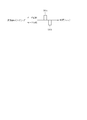
- an additional switching auxiliary operation (third auxiliary operation) is performed using the energization pattern (energization timing) shown in FIG.
- the energization pattern means the energization timing shown in FIG.
- the energization pattern has energization units 96a and 96b as shown in FIG.
- the energization unit 96a is energization for normal motor rotation
- the energization unit 96b is energization for motor reversal.
- the energization units 96a and 96b are set as one set, and this is performed once.
- the voltage waveform shown in FIG. 6 is used as the voltage waveform used here.
- the energization pattern (energization timing) in the fifth embodiment has a simple configuration, unlike the energization pattern described in the first embodiment, for example. Thereby, the overall time of the clutch switching operation can be shortened by shortening the additional switching auxiliary operation time.
- the energization pattern is set as one set of the energization units 96a and 96b.
- the energization units 96a and 96b are changed. You may perform control which makes this a plurality of times as one set.
Landscapes
- Engineering & Computer Science (AREA)
- Textile Engineering (AREA)
- Main Body Construction Of Washing Machines And Laundry Dryers (AREA)
- Detail Structures Of Washing Machines And Dryers (AREA)
- Control Of Washing Machine And Dryer (AREA)
Abstract
実施形態に係る洗濯機は、誘導モータを用いてパルセータ及び脱水槽を回転させるものである。この洗濯機は、パルセータの回転軸のみに誘導モータからの駆動力を伝達する第1状態と、パルセータの回転軸及び脱水槽の回転軸へ誘導モータからの駆動力を伝達する第2状態との切替えを行うクラッチを有する。また、誘電モータに印加される電源電圧を検知する電圧検知部を有し、クラッチの切替動作時に、誘導モータに所定の通電パターンを付与することによりクラッチの切替の補助動作を行う。そして、電圧検知部により検知した電源電圧の高低に応じて、通電パターンを変化させる。
Description
本発明の実施形態は、洗濯機に関する。
従来、誘導モータにより洗濯漕を駆動する洗濯機において、クラッチの切替を補助するために、誘導モータに対して所定の通電パターンを適用する場合がある。また、誘導モータは電源電圧の変動により影響を受けやすく、誘導モータの動作量、動作速度が変化してしまう。従って、電圧が低い場合では、誘導モータの動作量が小さくなり、動作速度が遅くなることで、クラッチの切替が正常に行われなくなってしまう場合がある。一方、電圧が高い場合では、誘導モータの動作量が大きくなり、動作速度が速くなることで、クラッチに負荷を与えてしまい、例えば機械的な故障を誘発する可能性があった。また、家庭用の太陽光発電の普及や、海外の電源事情が不安定な地域においては、電源電圧が変動することも多く、クラッチ切替において電圧変動を考慮する必要性が高まってきた。
そこで、電源電圧が変化しても、クラッチ切替の精度や信頼性を向上させることができる洗濯機を提供する。
実施形態に係る洗濯機は、誘導モータを用いてパルセータ及び脱水槽を回転させるものである。この洗濯機は、パルセータの回転軸のみに誘導モータからの駆動力を伝達する第1状態と、パルセータの回転軸及び脱水槽の回転軸へ誘導モータからの駆動力を伝達する第2状態との切替えを行うクラッチを有する。また、誘電モータに印加される電源電圧を検知する電圧検知部を有し、クラッチの切替動作時に、誘導モータに所定の通電パターンを付与することによりクラッチの切替の補助動作を行う。そして、電圧検知部により検知した電源電圧の高低に応じて、通電パターンを変化させる。
以下、実施形態について図面を参照しながら説明する。なお、各実施形態で実質的に同一の要素には同一の符号を付し、説明を省略する。なお、以下の説明において、通電パターンとは、例えば後述する図5、図7、図8、図9、図12に示す通電タイミングを意味する場合もあり、また、例えば後述する図10、図11に示す電圧波形を意味する場合もある。
(第1の実施形態)
以下、第1の実施形態による洗濯機について、図1から図7を参照しながら説明する。まず、図1は、洗濯機1の概略構成を示している。ここで、ほぼ矩形箱状をなす外箱2内には、脱水時等に水を受ける水槽3が弾性吊持機構4を介して設けられている。そして、前記水槽3内には、内部に洗濯物が収容される洗い槽兼脱水槽としての回転槽5が回転可能に設けられており、またその回転槽5内の底部には、水流生成用の撹拌体(パルセータ)6が設けられている。
以下、第1の実施形態による洗濯機について、図1から図7を参照しながら説明する。まず、図1は、洗濯機1の概略構成を示している。ここで、ほぼ矩形箱状をなす外箱2内には、脱水時等に水を受ける水槽3が弾性吊持機構4を介して設けられている。そして、前記水槽3内には、内部に洗濯物が収容される洗い槽兼脱水槽としての回転槽5が回転可能に設けられており、またその回転槽5内の底部には、水流生成用の撹拌体(パルセータ)6が設けられている。
図2、図3にも示すように、前記水槽3の外底部には、駆動用のモータ7及び、そのモータ7の回転駆動力が、ベルト伝達機構8を介して伝達される駆動機構部9が設けられている。モータ7は誘導モータにより構成されている。駆動機構部9の構成については後述する。
これらモータ7、ベルト伝達機構8、駆動機構部9により、洗剤洗いやすすぎ洗いの運転においては、前記撹拌体6が正逆回転されて回転槽5内に撹拌水流が生成され、脱水運転においては、前記回転槽5が撹拌体6と一体的に高速回転されるようになっている。尚、図1での図示は省略するが、前記水槽3の底部には、前記回転槽5からの排水を行うための排水弁71等が設けられている(図4参照)。
一方、前記回転槽5の上端部にはバランスリング10が装着されていると共に、脱水時の該回転槽5からの排水を、そのバランスリング10との間を通して行うための脱水孔11が設けられている。また、前記水槽3の上端部には、ほぼリング状をなす桶カバー12が設けられている。前記外箱2の上端部には、プラスチック製のトップカバー13が設けられている。
このトップカバー13は、中央にほぼ円形の洗濯物出入口を有すると共に、その洗濯物出入口を開閉するための二つ折りタイプの蓋14が設けられている。尚、図示はしないが、前記トップカバー13の後辺部には、給水弁等を有する給水機構等が設けられ、トップカバー13の前辺部には、操作入力部(操作パネル)61や、マイコンを主体とし洗濯機1全体を制御する制御装置60などが設けられている(図4参照)。
ここで、前記駆動機構部9について、図2及び図3も参照して述べる。図2は、クラッチ15が洗い位置(上昇した位置)にある様子を示し、図3は、前記クラッチ15が脱水位置(下降した位置)にある様子を示している。前記水槽3の外底部には、軸受ハウジング16が取付けられている。この軸受ハウジング16は、上フレーム17と下フレーム18とを外周側部分にて結合して構成されている。上フレーム17の中央部には、上向きに凸となる円筒部17aが形成されていると共に、下フレーム18の中央部には下向きに凸となる円筒部18aが形成されている。
前記円筒部17a内には、ボールベアリングからなる軸受19が嵌合固着され、この軸受19に支持されて中空状(円管状)の上部槽軸20が設けられている。この上部槽軸20の上端部にはフランジ部20aが一体に設けられ、このフランジ部20aに前記回転槽5が固着されている。上部槽軸20の中空部内には、上部撹拌軸21が上下に貫通するように挿通され、このとき、上部撹拌軸21は、軸受メタル22,23を介して回転自在に支持されている。上部撹拌軸21の上端部は、前記撹拌体6に連結されている。前記円筒部17aの上端内周面と前記上部槽軸20の外周面との間には、シール部材24が設けられている。
一方、前記下フレーム18の円筒部18a内には、ボールベアリングからなる軸受25が嵌合固着され、この軸受25に支持されて中空状(円管状)の下部槽軸26が設けられている。下部槽軸26の中空部内には、下部撹拌軸27が、上下に貫通し且つ軸受メタル28,29を介して回転自在に支持されている。下部撹拌軸27の下端部には、従動プーリ30が取付けられていると共に、その従動プーリ30の上面部に位置してボス部31が固着されている。これにより、ボス部31は下部撹拌軸27と一体回転する。
前記モータ7は、前記上フレーム17の下面側に下向きに設けられおり、その出力軸7aに駆動プーリ32が取付けられている。駆動プーリ32と前記従動プーリ30との間に、Vベルト33が掛渡されている。これにて、ベルト伝達機構8が構成され、モータ7の回転が、間接的に前記下部撹拌軸27に伝達されて回転されるようになっている。
上部槽軸20と下部槽軸26との間は、ギアケース34により連結され、前記上部撹拌軸21と下部撹拌軸27との間は、ギアケース34内に配設された遊星歯車装置からなる減速ギア機構35を介して連結されている。このとき、前記ギアケース34は、下面が開口した径大な円筒状をなすと共に、その上面部に径小な突出筒部34aを一体に有している。前記突出筒部34aが前記上部槽軸20の下端部に連結されている。また、前記下部槽軸26の上端部には、外周方向に拡がるフランジ状部26aが一体に設けられ、このフランジ状部26aが、前記ギアケース34の下面を塞ぐようにして該ギアケース34の下端部と連結されている。
前記減速ギア機構35は、前記下部撹拌軸27の上端に設けられた外歯車36、前記ギアケース34の内周面部に設けられた内歯車37、それら外歯車36と内歯車37との間に設けられた複数個(例えば3個)の遊星歯車38、複数個の遊星歯車38の各軸部を連結するように設けられたキャリア39を備えて構成されている。前記キャリア39の中心部が上部撹拌軸21の下端部に連結されている。
クラッチ15が洗い位置にある状態(図2参照)では、下部槽軸26、ギアケース34、上部槽軸20が、撹拌軸21,27から切離されて水槽3側(下フレーム18)に固定されるようになる。この状態では、下部撹拌軸27の回転が、減速ギア機構35により減速されて上部撹拌軸21が回転される。この上部撹拌軸21の回転により、撹拌体6が一体回転される。
これに対し、クラッチ15が脱水位置にある状態(図3参照)では、下部槽軸26が下部撹拌軸27に連結され、この結果、下部槽軸26、ギアケース34、減速ギア機構35、上部槽軸20、上部撹拌軸21が一体的に連結された状態とされる。この状態では、下部撹拌軸27の回転が上部槽軸20に伝達され、ひいては回転槽5が一体回転される。
上記のように、前記下部槽軸26の下部外周部には、該下部槽軸26と前記下部撹拌軸27(ボス部31)との連結及び切離しを行なうためのクラッチ15が設けられている。更に、前記下フレーム18の下面部には、このクラッチ15を上下動させてその状態を切替えるためのクラッチ切替手段としての昇降機構40が設けられると共に、共回り防止部41が設けられる。
前記クラッチ15は、全体としてほぼ円筒状をなしている。このクラッチ15の上端部には、円形鍔状(フランジ状)の被係合部42が一体に形成されている。被係合部42には、上面外周部に位置して円周方向に並んだ複数(例えば12個)の歯部42aが形成されている。クラッチ15は、その内周面全周に、上下方向に延びる内セレーション部43が形成されている。
これに対し、図2、図3に示すように、前記下部槽軸26の下半部(前記軸受25から下方に突出した部位)の外周部には、前記内セレーション部43に対応して上下方向に延びるセレーション部44が形成されている。前記クラッチ15は、内セレーション部43が前記セレーション部44に常に係合されることにより、下部槽軸26の下端部外周に上下動可能且つ周方向に一体的に回転するように嵌挿されている。クラッチ15の上面と前記軸受25の内輪との間には、下部槽軸26の外周部に位置してコイルばね45が配設され、クラッチ15は常に下降位置(脱水位置)に向けて付勢されている。
クラッチ15の下端部には、前記ボス部31に嵌合する複数個例えば4個の嵌合凹部15aと嵌合凸部15bとが円周方向に交互に設けられている。この場合、前記ボス部31の上面には、前記嵌合凹部15aと嵌合凸部15bとが嵌合される歯部46と凹部47とが円周方向に交互に設けられている。前記共回り防止部41は、前記円筒部18aの外周部に位置して、前記クラッチ15の上端の被係合部42(歯部42a)が係合する係合部48(凹部)を有している。
これにて、クラッチ15が図3に示す下降した脱水位置にあるときには、クラッチ15の下端部の嵌合凹部15a及び嵌合凸部15bがボス部31の上面に嵌合し、もってボス部31ひいては下部撹拌軸27と下部槽軸26とを一体回転するように連結する。これに対し、クラッチ15が図2に示す上昇した洗い位置にあるときには、ボス部31から切離される。また、これと共に、クラッチ15の上端の被係合部42が係合部48に係合し、クラッチ15(及び下部槽軸26)が下フレーム18(水槽3)に固定されて回転不能とされ、下部撹拌軸27が回転可能とされるようになっている。
一方、前記昇降機構40は、図2、図3に示すように、前記クラッチ15を上下動させるクラッチレバー49、このクラッチレバー49を揺動させる操作レバー50等を備えて構成される。このクラッチレバー49は、前記共回り防止部41に一体に設けられる支持部41aにその中間部が上下方向に揺動可能に支持され、先端部には、前記クラッチ15の被係合部42の下面側に係止して押し上げるための当接部(図示略)を有している。また、図2に示すように、クラッチレバー49の基端部側と前記支持部41aとの間には、引張コイルばね51が配設され、クラッチレバー49の基端部の係止操作部49aが操作レバー50に対して常に係止されるようになっている。
前記操作レバー50は、前記下フレーム18にピン52により水平方向に回動可能に支持されており、その下部に、前記係止操作部49aが係止される傾斜状の係止部50aを有している。これにて、操作レバー50の水平方向の回動に伴い、クラッチレバー49の基端部が上下方向に動作されるようになっている。詳しい図示及び説明は省略するが、操作レバー50は、前記排水弁モータにより、前記排水弁の開閉と連動して駆動されるようになっている。前記共回り防止部41部分には、クラッチ15の位置を検出する図示しないクラッチ位置検出センサが設けられている。
以上のように構成された昇降機構40は、排水弁モータと共にクラッチ切替手段として機能している。昇降機構40は、洗い行程やためすすぎ洗いの行程においては、排水弁が閉塞される。また、これと共に、昇降機構40は、操作レバー50は図2の状態にあって、クラッチレバー49の基端部を押し下げており、クラッチレバー49の先端の当接部がクラッチ15をコイルばね45のばね力に抗して上方に押上げて洗い位置に位置させている。これに対し、脱水行程(及び脱水すすぎの行程)においては、排水弁が開放されることに伴い、操作レバー50が駆動され、図3に示すように、クラッチレバー49が揺動して先端の当接部が下降し、もってクラッチ15がコイルばね45のばね力によって脱水位置に下降される。
図4にも示されるように、前記モータ7や給水弁70、排水弁71等の各機構は、前記制御装置60により制御される。この制御装置60には、操作入力部61のキー操作信号が入力されると共に、水位センサ64、蓋スイッチ、クラッチ位置検出センサ等からの検出信号が入力される。制御装置60は、使用者による操作入力部61のキー操作及び前記各種の入力等に基づき、ROM等に記憶された制御プログラムに従って、前記モータ7や給水弁70、排水弁71等の各機構を制御する。制御装置60は、これにより、洗い行程、すすぎ行程(脱水すすぎ行程及びためすすぎ工程)、脱水行程に大別される洗濯運転を自動で実行する。
前記洗い行程、ためすすぎ行程では、撹拌体6が低速で正逆方向に交互に回転され、脱水すすぎ行程、脱水行程では、回転槽5及び撹拌体6が高速で一方向(正方向)に一体回転される。このとき、前記制御装置は、後の作用説明でも述べるように、洗濯運転の行程に応じてクラッチ切替指令(排水弁モータに対する回転駆動指令)を発生して、クラッチ15を洗い位置と脱水位置との間で切替制御する。即ち、クラッチ15は、洗い行程及びためすすぎ洗い行程の開始直前(排水弁71を閉鎖するタイミング)で洗い位置へ切替えられ、洗い行程、ためすすぎ行程の終了時(排水弁71の開放のタイミング)に、脱水位置へ切替えられる。
またこのとき、前記制御装置は、クラッチ15の切替え時(排水弁モータの駆動時)に、前記モータ7を短時間(全体で数秒~10秒程度)回転させて停止させる切替補助動作を実行させる。この切替補助動作は、モータ7を正方向及び反転方向へ、所定の通電パターンで、小刻みに回転させることにより行われる。これにより、クラッチ15の洗い位置への切替え時には、クラッチ15の被係合部42の共回り防止部41の係合部48に対する係合が促され、脱水位置への切替え時には、クラッチ15の下端部のボス部31に対する嵌合が促されるようになっている。これについては後述する。
外箱1内の後部の下部には、制御手段を構成する制御装置60が設けられている。図4には、この制御装置60を中心とした電気的構成の概略が示されている。制御装置60は、マイクロコンピュータ(CPU、ROM、RAMを含む)及び不揮発性メモリを主体に構成されたもので、洗濯機1の作動全般を制御する機能を備えている。
制御装置60には、操作入力部61の操作信号が表示用制御部35を介して入力される。制御装置60には、水槽3内に貯留される水の水位を検出する水位センサ64の水位検知信号、モータ7の回転速度を検知する回転センサ65の回転速度検知信号、モータ7に流れる電流を検知する電流センサ66の電流検知信号、安全レバースイッチ装置67の揺動検知信号、加速度センサ68の揺動検知信号などが入力されるようになっている。
制御装置60は、これらの入力信号、並びに予めROMに格納されていてRAMに読み出された制御プログラおよびデータに基づき、表示用制御部63を介して表示部62を制御する。また、制御装置60は、給水弁70、排水弁71、モータ7などを、駆動回路76を介して制御する。上述の切替補助動作は制御装置60によるモータ7の制御により行われる。
制御装置60には電源入スイッチ72を介して電源75が接続されている。電源入スイッチ72と制御装置60間には、この間の電圧を検知するための電圧検知部73が配設されている。電圧検知部73によりモータ7に印加される電源電圧の検知がなされる。電圧検知部73によって検知された電圧の電圧値信号は制御装置60に送信され、制御装置60において、検知された電源電圧は基準電圧と比較され、その高低が判定される。また、制御装置60には、電源切スイッチ74が接続されている。
電圧検知部73による電源電圧の検知は、洗濯機1の電源入スイッチ72により電源投入から、クラッチ切替を行うまでの間に実施することができる。電源電圧値としては、例えば、電源投入時に検知した電源電圧を用いたり、電源投入後の所定時間経過後、例えば電源投入から5秒後の電源電圧を用いることとしてもよい。電源投入後、暫くの時間が経過した後の方が、電源電圧が安定すると考えられるので、この方が望ましいと言える。
また、電源電圧値は、電源投入後の所定時間経過毎に複数の電源電圧を検知し、その電源電圧値の平均値を用いてもよい。また、運転スタートした時点、クラッチ切替を行う直前(洗い行程終了後の排水弁71が開放された直後)の電源電圧を用いることとしてもよい。また、クラッチ切替のモータ7への通電を開始する時点で検知してもよいし、クラッチ切替前の所定時間の平均値(例えば、100msec毎のサンプリングで3秒間の平均)を用いてもよい。
以下、本実施形態における切替補助動作について詳細に説明する。第1の実施形態においては、通電パターンは、図5(b)~(d)、及び、図7(b)~(d)に示す通電タイミングを意味する。
図5は第1の実施形態において、洗い行程から脱水行程に移行する際のクラッチ切替時の切替補助動作(第1補助動作)のモータ7への通電パターン(通電タイミング)を示している。
図5(a)は、洗い行程から脱水行程への切り替わり時の、排水弁71の閉鎖状態から開放状態への切り替わりタイミングを示している。排水弁71が閉鎖状態の期間は洗い行程であり、時刻T1において閉鎖状態から開放状態に切り替わる。時刻T1の後、脱水行程への移行動作として、クラッチ15の切替を開始する。
図5(b)は、クラッチ15の切替補助動作において、電圧検知部73において検知される電源電圧が基準電圧である場合の通電パターン(通電タイミング)を示している。ここでは、通電パターンは、図5(b)に示す通電タイミングを意味する。
基準電圧とは、例えば220±20[V]である。この範囲を上回ると高い電圧、下回ると低い電圧と判定される。通電パターンは、図5(b)に示すように、通電単位80a、80b、及び通電単位81を有している。ここでは、モータ正転の通電単位80aと、モータ反転の通電単位80bを1セットとして、これを3セット分繰り返し、さらに、モータ正転の通電単位81を3回通電している。
通電単位80a及び80bの時間長さは例えば0.1秒であり、通電単位80a-80b間の時間長さは例えば0.7秒である。通電単位80bと通電単位81間は例えば2.0秒である。通電単位81の時間長さは0.1秒であり、通電単位81間の時間長さは例えば0.5秒である。
通電単位80a、80b、81の通電時間中は、図6に示すような正弦波の電圧波形により構成される交流電源が与えられる。図6に示す交流電源は、例えば単相2線220V、周波数50Hzである。通電単位80a及び80bにより、クラッチ15の被係合部42の共回り防止部41の係合部48に対する係合が外されることを促している。また、通電単位81により、クラッチ15の下端部のボス部31に対する嵌合が促されるようになっている。
図5(c)は電圧検知部73において検知される電源電圧が基準電圧よりも高い電圧である場合の通電パターン(通電タイミング)を示している。ここでは、通電パターンは、図5(c)示す通電タイミングを意味する。電源電圧が基準電圧よりも高い電圧である場合は、電源電圧が基準電圧である場合に比較して、通電単位80a、80b及び81の数を少なくすることによって通電回数を少なくしている。すなわち、通電パターンは、図5(b)に示すように、モータ正転の通電単位80aと、モータ反転の通電単位80bを1セットとして、これを2セット分繰り返し、さらに、モータ正転の通電単位81を2回通電している。
通電単位80a、80b、81の通電時間長さは図5(a)におけるものと同じであり、また、通電単位80a、80b、81の間隔も同様である。このようにすることで、電源電圧が高い場合にも、モータ7の動作量、モータ7の動作速度を低くすることができる。これにより、基準電圧を付与した場合と同様のモータ7の動作量、動作速度に抑えることができるため、クラッチに負荷を与えてしまうことで例えば機械的な故障を誘発することを抑制できる。
図5(d)は電圧検知部73において検知される電源電圧が基準電圧よりも低い電圧である場合に対応した通電パターン(通電タイミング)を示している。ここでは、通電パターンは、図5(d)に示す通電タイミングを意味する。電源電圧が基準電圧よりも低い電圧である場合は、電源電圧が基準電圧である場合に比較して、通電単位80a、80b及び81の数を多くすることによって通電回数を多くしている。すなわち、通電タイミングは、図5(d)に示すように、モータ正転の通電単位80aと、モータ反転の通電単位80bを1セットとして、これを4セット分繰り返し、さらに、モータ正転の通電単位81を4回通電している。
通電単位80a、80b、81の通電時間長さは図5(b)におけるものと同じであり、また、通電単位80a、80b、81の間隔も同様である。これにより、電源電圧が基準電圧よりも低いためにモータ7の動作量が少なく動作速度が遅くなってしまい、クラッチ15の切替が正常に行われない可能性がある場合にも、基準電圧を付与した場合と同様のモータ7の動作量、動作速度に高めることができる。これにより、確実にクラッチ15の切替を実現できる。すなわち、通電単位80a及び80bにより、クラッチ15の被係合部42の共回り防止部41の係合部48に対する係合が外されることを十分に促し、通電単位81により、クラッチ15の下端部のボス部31に対する嵌合が十分に促されるようになる。
図7は第1の実施形態において、脱水行程から洗い行程に移行する際のクラッチ切替時の切替補助動作(第2補助動作)時のモータ7への通電パターン(通電タイミング)を示している。図7(a)は、脱水行程から洗い(すすぎ)行程への切り替わり時の、排水弁71の開放状態から閉鎖状態への切り替わりタイミングを示している。排水弁71が閉鎖状態の期間は洗い(すすぎ)行程であり、時刻T2において開放状態から閉鎖状態に切り替わり、脱水行程への準備動作として、クラッチ15の切替を開始する。
図7(b)は、電圧検知部73において検知される電源電圧が基準電圧である場合に対応した通電パターン(通電タイミング)を示している。ここでは、通電パターンは、図7(b)に示す通電タイミングを意味する。基準電圧とは、例えば220±20[V]である。通電パターンは、図7(b)に示すように、通電単位82a、82b、83a、83bを有している。
ここでは、モータ正転の通電単位82aと、モータ反転の通電単位82bを1セットとして、これを3セット分繰り返し、さらに、モータ正転の通電単位83aと、モータ反転の通電単位83bを1セットとして、これを2セット分繰り返して通電している。通電単位82a、82bの時間長さは例えば0.1秒であり、通電単位82a-82b間の時間長さは例えば0.7秒である。通電単位82bと通電単位83a間の時間長さは例えば0.7秒である。通電単位83a及び83bの時間長さは0.5秒であり、通電単位83a-83b間は例えば0.7秒である。
通電単位82a、82b、83a、83bの通電時間中は、図6に示すような正弦波より構成される交流電源が与えられる。図6に示す交流電源は、例えば単相2線220V、周波数50Hzである。通電単位82a及び82bにより、クラッチ15の被係合部42の共回り防止部41の係合部48に対する係合が外されることを促している。また、通電単位83a、83bにより、クラッチ15の下端部のボス部31に対する嵌合が促されるようになっている。
図7(c)は電圧検知部73において検知される電源電圧が基準電圧よりも高い電圧である場合に対応した通電パターン(通電タイミング)を示している。ここでは、通電パターンは、図7(c)に示す通電タイミングを意味する。電源電圧が基準電圧よりも高い電圧である場合は、電源電圧が基準電圧である場合に比較して、通電単位82a、82b及び83a、83bの数を少なくすることによって通電回数を少なくしている。すなわち、通電パターンにおいては、図7(c)に示すように、モータ正転の通電単位82aと、モータ反転の通電単位82bを1セットとして、これを2セット分繰り返される。さらに、通電パターンにおいては、モータ正転の通電単位83aとモータ反転の通電単位83bを1セットとして、これを1セット分通電される。
通電単位82a、82b、83a、83bの通電時間長さは図7(b)におけるものと同じであり、また、通電単位82a、82b、83a、83bの間隔も同様である。このようにすることで、電源電圧が基準電圧より高い場合にも、モータ7の動作量、モータ7の動作速度を低くすることができる。これにより、基準電圧を付与した場合と同様のモータ7の動作量、動作速度に抑えるこができるため、クラッチに負荷を与えてしまうことで例えば機械的な故障を誘発することを抑制できる。
図7(d)は電圧検知部73において検知される電源電圧が基準電圧よりも低い電圧である場合に対応した通電パターン(通電タイミング)を示している。ここでは、通電パターンは、図7(d)に示す通電タイミングを意味する。電源電圧が基準電圧よりも低い電圧である場合は、電源電圧が基準電圧である場合に比較して、通電単位82a、82b、83a、83bの数を多くすることによって通電回数を多くしている。すなわち、通電パターンにおいては、図7(d)に示すように、モータ正転の通電単位82aと、モータ反転の通電単位82bを1セットとして、これを4セット分繰り返される。さらに、通電パターンにおいては、モータ正転の通電単位83aとモータ反転の通電単位83bを1セットとして、これを3セット分繰り返して通電される。
通電単位82a、82b、83a、83bの通電時間長さは図7(b)におけるものと同じであり、また、通電単位82a、82b、83a、83bの間隔も同様である。これにより、電源電圧が基準電圧よりも低いためにモータ7の動作量が少なく動作速度が遅くなってしまい、クラッチ15の切替が正常に行われない可能性がある場合にも、基準電圧を付与した場合と同様のモータ7の動作量、動作速度に高めることができる。これにより、確実にクラッチ15の切替を実現できる。すなわち、通電単位82a及び82bにより、クラッチ15の被係合部42の共回り防止部41の係合部48に対する係合が外されることを十分に促し、通電単位83a、83bにより、クラッチ15の下端部のボス部31に対する嵌合が十分に促されるようになる。
以上説明したように、第1の実施形態によれば、電圧検知部73において検知される電源電圧の高低により、クラッチ切替時の切替補助動作のモータ7の通電パターン(通電タイミング)を変化させる。すなわち、電源電圧が基準電圧よりも高い場合には、通電単位80、81、82、83の数を減らした通電パターンを用いる。これにより、切替補助動作のモータ7の出力を抑えられるので、電圧が高い場合であってもモータ7の動作量、モータ7の動作速度を抑えることができる。基準電圧を付与した場合と同様のモータ7の動作量、動作速度に抑えることができるため、クラッチに負荷を与えてしまうことで例えば機械的な故障を誘発することを抑制できる。
一方、電源電圧が基準電圧よりも低い場合には、通電単位80、81、82、83の数を増やした通電パターンを用いる。これにより、基準電圧を付与した場合と同様のモータ7の動作量、動作速度に高めるこができるため、クラッチの切替をより確実にすることができる。
(第2の実施形態)
以下、第2の実施形態について説明する。第1実施形態において説明に用いた図1から図4及び図6については第2の実施形態においても共通である。第2の実施形態においては、通電パターンは、図8(b)~(d)、図9(b)~(d)に示す通電タイミングを意味する。
以下、第2の実施形態について説明する。第1実施形態において説明に用いた図1から図4及び図6については第2の実施形態においても共通である。第2の実施形態においては、通電パターンは、図8(b)~(d)、図9(b)~(d)に示す通電タイミングを意味する。
図8は第2の実施形態において、洗い行程から脱水行程に移行する際のクラッチ切替時の切替補助動作(第1補助動作)の通電パターンを示している。図8(a)は、洗い行程から脱水行程への切り替わり時の、排水弁71の閉鎖状態から開放状態への切り替わりタイミングを示している。排水弁71が閉鎖状態の期間は洗い行程であり、時刻Tにおいて閉鎖状態から開放状態に切り替わり、脱水行程への切替動作として、クラッチ15の切替を開始する。
図8(b)は、電圧検知部73において検知される電源電圧が基準電圧である場合に対応した通電パターン(通電タイミング)を示している。ここでは、通電パターンは、図8(b)に示す通電タイミングを意味する。基準電圧とは、例えば220±20[V]である。通電パターンは、図8(b)に示すように、通電単位84a、84b、及び通電単位85を有している。
ここでは、モータ正転の通電単位84aと、モータ反転の通電単位84bを1セットとして、これを3セット分繰り返し、さらに、モータ正転の通電単位85を3回通電している。通電単位84a及び84bの時間長さは例えば0.1秒であり、通電単位84a-84b間の時間長さは例えば0.7秒である。通電単位84bと通電単位85間は例えば2.0秒である。通電単位85の時間長さは0.1秒であり、通電単位85間の時間長さは例えば0.5秒である。
通電単位84a、84b、85の通電時間中は、図6に示すような正弦波より構成される交流電源が与えられる。通電単位84a及び84bにより、クラッチ15の被係合部42の共回り防止部41の係合部48に対する係合が外されることを促している。また、通電単位85により、クラッチ15の下端部のボス部31に対する嵌合が促されるようになっている。
図8(c)は電圧検知部73において検知される電源電圧が基準電圧よりも高い電圧である場合に対応した通電パターン(通電タイミング)を示している。ここでは、通電パターンは、図8(c)に示す通電タイミングを意味する。電源電圧が基準電圧よりも高い電圧である場合は、電源電圧が基準電圧である場合に比較して、通電単位86a、86b、及び通電単位87のそれぞれの時間長さを短くすることによって通電時間を少なくしている。
通電パターンは、図8(c)に示すように、通電単位86a、86b、及び通電単位87の通電時間を0.05秒として通電している。すなわち、図8(b)に示す通電単位84a、84b、及び通電単位85の半分の時間としている。
通電単位86a、86b、及び通電単位87の通電回数は図8(b)におけるものと同じであり、また、通電単位86a、86b、及び通電単位87の間隔も同様である。このようにすることで、電源電圧が高い場合にも、モータ7の動作量、モータ7の動作速度を低くすることができる。これにより、基準電圧を付与した場合と同様のモータ7の動作量、動作速度に抑えることができるため、クラッチに負荷を与えてしまうことで例えば機械的な故障を誘発することを抑制できる。
図8(d)は電圧検知部73において検知される電源電圧が基準電圧よりも低い電圧である場合の通電パターン(通電タイミング)を示している。ここでは、通電パターンは、図8(d)に示す通電タイミングを意味する。電源電圧が基準電圧よりも低い電圧である場合は、電源電圧が基準電圧である場合に比較して、通電単位88a、88b、及び通電単位89のそれぞれの時間長さを長くすることによって通電時間を長く(多く)している。通電パターンは、図8(d)に示すように、通電単位88a、88b、及び通電単位89の通電時間を0.2秒として通電している。すなわち、図8(b)に示した通電単位84a、84b、85a、85bの半分の時間としている。
通電単位88a、88b、及び通電単位89の通電回数は図8(b)におけるものと同じであり、また、通電単位88a、88b、及び通電単位89の間隔も同様である。これにより、電源電圧が基準電圧よりも低いためにモータ7の動作量が少なく動作速度が遅くなってしまい、クラッチ15の切替が正常に行われない可能性がある場合にも、基準電圧を付与した場合と同様のモータ7の動作量、動作速度に高めることができる。これにより、確実にクラッチ15の切替を実現できる。すなわち、通電単位88a及び88bの時間が長くなったことにより、クラッチ15の被係合部42の共回り防止部41の係合部48に対する係合が外されることを十分に促す。また、通電単位89bの時間が長くなったことにより、クラッチ15の下端部のボス部31に対する嵌合が十分に促されるようになる。
図9は第2の実施形態において、脱水行程から洗い行程に移行する際のクラッチ切替時の切替補助動作時(第2補助動作)の通電パターン(通電タイミング)を示している。図9(a)は、脱水行程から洗い(すすぎ)行程への切り替わり時の、排水弁71の開放状態から閉鎖状態への切り替わりタイミングを示している。排水弁71が閉鎖状態の期間は洗い(すすぎ)行程であり、時刻T2において開放状態から閉鎖状態に切り替わり、脱水行程への準備動作として、クラッチ15の切替を開始する。
図9(b)は、電圧検知部73において検知される電源電圧が基準電圧である場合の通電パターンを示している。ここでは、通電パターンは、図9(b)に示す通電タイミングを意味する。基準電圧とは、例えば220±20[V]である。通電パターンは、図9(b)に示すように、通電単位90a、90b、91a、91bを有している。ここでは、モータ正転の通電単位90aと、モータ反転の通電単位90bを1セットとして、これを3セット分繰り返し、さらに、モータ正転の通電単位92aと、モータ反転の通電単位92bを1セットとして、これを2セット分繰り返して通電している。通電単位90a、90bの時間長さは例えば0.1秒であり、通電単位90a-90b間の時間長さは例えば0.7秒である。通電単位90bと通電単位91a間の時間長さは例えば0.7秒である。通電単位91a及び91bの時間長さは0.5秒であり、通電単位91a-91b間は例えば0.7秒である。
通電単位90a、90b、91a、91bの通電時間中は、図6に示すような正弦波より構成される交流電源が与えられる。通電単位90a及び90bにより、クラッチ15の被係合部42の共回り防止部41の係合部48に対する係合が外されることを促している。また、通電単位91a、91bにより、クラッチ15の下端部のボス部31に対する嵌合が促されるようになっている。
図9(c)は電圧検知部73において検知される電源電圧が基準電圧よりも高い電圧である場合の通電パターン(通電タイミング)を示している。ここでは、通電パターンは、図9(c)に示す通電タイミングを意味する。電源電圧が基準電圧よりも高い電圧である場合は、電源電圧が基準電圧である場合に比較して、通電単位92a、92b及び93a、93bのそれぞれの時間長さを短くすることによって通電時間を少なくしている。通電パターンは、図9(c)に示すように、通電単位92a、92bの通電時間を0.05秒として通電している。また、通電単位93a、93bの通電時間を0.25秒として通電している。すなわち、図9(b)に示した通電単位90a、90b、91a、91bの半分の時間としている。
通電単位92a、92b、93a、93bの通電回数は図9(b)におけるものと同じであり、また、通電単位92a、92b、93a、93bの間隔も同様である。このようにすることで、電源電圧が高い場合にも、モータ7の動作量、モータ7の動作速度を低くすることができる。これにより、基準電圧を付与した場合と同様のモータ7の動作量、動作速度に抑えることができるため、クラッチに負荷を与えてしまうことで例えば機械的な故障を誘発することを抑制できる。
図9(d)は電圧検知部73において検知される電源電圧が基準電圧よりも低い電圧である場合の通電パターン(通電タイミング)を示している。ここでは、通電パターンは、図9(d)に示す通電タイミングを意味している。電源電圧が基準電圧よりも低い電圧である場合は、電源電圧が基準電圧である場合に比較して、通電単位94a、94b、及び通電単位95a、95bのそれぞれの時間長さを長くすることによって通電時間を長く(多く)している。
通電パターンは、図9(d)に示すように、通電単位94a、94bの通電時間を0.2秒として通電している。また、通電単位95a、95bの通電時間を1.0秒として通電している。すなわち、図9(b)に示した通電単位90a、90b、91a、91bの2倍の時間としている。通電単位94a、94b、及び通電単位95a、95bの通電回数は図9(b)におけるものと同じであり、また、通電単位94a、94b、及び通電単位95a、95bの間隔も同様である。
これにより、電源電圧が基準電圧よりも低いためにモータ7の動作量が少なく動作速度が遅くなってしまい、クラッチ15の切替が正常に行われない可能性がある場合にも、基準電圧を付与した場合と同様のモータ7の動作量、動作速度に高めることができる。これにより、確実にクラッチ15の切替を実現できる。すなわち、通電単位94a、94bの時間が長くなったことにより、クラッチ15の被係合部42の共回り防止部41の係合部48に対する係合が外されることを十分に促す。また、通電単位95a、95bの時間が長くなったことにより、クラッチ15の下端部のボス部31に対する嵌合が十分に促されるようになる。
以上説明したように、第2の実施形態によれば、電圧検知部73において検知される電源電圧の高低により、クラッチ切替時の切替補助動作のモータ7の通電パターン(通電タイミング)を変化させる。すなわち、電源電圧が基準電圧よりも高い場合には、通電単位84、85、90、91のそれぞれの時間の長さを短くした通電パターン(通電単位86、87、92,93)を用いる。これにより、切替補助動作のモータ7の出力を抑えられるので、電圧が高い場合であってもモータ7の動作量、モータ7の動作速度を抑えることができる。基準電圧を付与した場合と同様のモータ7の動作量、動作速度に抑えることができるため、クラッチに負荷を与えてしまうことで例えば機械的な故障を誘発することを抑制できる。
一方、電源電圧が基準電圧よりも低い場合には、通電単位84、85、90、91のそれぞれの時間の長さを短くした通電パターン(通電単位88、89、94,95)を用いる。これにより、基準電圧を付与した場合と同様のモータ7の動作量、動作速度に高めることができるため、クラッチの切替をより確実にすることができる。
(第3の実施形態)
以下、第3の実施形態について説明する。第1実施形態において説明に用いた図1から図4については第3の実施形態においても共通である。第3の実施形態においては、通電パターンは、図10(a)~(c)に示す交流電源の電圧波形を意味する。
以下、第3の実施形態について説明する。第1実施形態において説明に用いた図1から図4については第3の実施形態においても共通である。第3の実施形態においては、通電パターンは、図10(a)~(c)に示す交流電源の電圧波形を意味する。
図10は、第3の実施形態においてモータ7に与えられる通電パターン(電圧波形)を示している。第3の実施形態で用いられる通電タイミングは、例えば、第1の実施形態における図5(b)~(d)、図7(b)~(d)に示した通電タイミングが用いられる。第3の実施形態においては、交流電源の電圧波形の位相制御を行い、電圧波形の周期毎におけるON時間の割合を変化させることでモータ7への通電パターン(電圧波形)を連続的に制御する。
図10(a)は、電圧検知部73において検知される電源電圧が基準電圧である場合の通電パターン(電圧波形)を示している。図10(a)において横軸は時間、縦軸は電圧を示している。図10(a)に示す交流電源の正弦波形のゼロクロスポイント毎に区切った各1/2(2分の1)波長分の時間tのうち、それぞれが70%の通電時間となるように制御している。
図10(b)は、電圧検知部73において検知される電源電圧が基準電圧よりも高い電圧である場合の通電パターン(電圧波形)を示している。図10(b)に示す交流電源の正弦波形のゼロクロスポイント毎に区切った各1/2波長分の時間のうち、それぞれが40%の通電時間となるように制御している。
このようにすることで、電源電圧が高い場合にも、モータ7の動作量、モータ7の動作速度を低くすることができる。これにより、基準電圧を付与した場合と同様のモータ7の動作量、動作速度に抑えることができるため、クラッチに負荷を与えてしまうことで例えば機械的な故障を誘発することを抑制できる。
図10(c)は、電圧検知部73において検知される電源電圧が基準電圧よりも低い電圧である場合の通電パターン(電圧波形)を示している。図10(c)に示す交流電源の正弦波形のゼロクロスポイント毎に区切った各1/2波長分の時間のうち、それぞれが100%の通電時間となるように制御している。
このようにすることで、電源電圧が低い場合にも、モータ7の動作量、モータ7の動作速度を増加させることができる。これにより、電源電圧が基準電圧である場合の、図10(a)に示す通電パターン(電圧波形)と同様のモータ7の動作量、動作速度にすることができるため、クラッチの切替をより確実にすることができる。
上述のように、第3の実施形態においては、電源電圧の高低により、通電パターン(電源電圧の正弦波の位相制御)を行うことで通電率を変化させ、電源電圧に応じたモータ7の動作量、動作速度を実現している。
なお、電源電圧が基準電圧である場合や低い場合には図10(c)に示す100%通電の制御とし、電源電圧が高い場合のみに位相制御で通電率を70%に下げるという方法を採用してもよい。また、電源電圧が基準電圧である場合や高い場合図10(b)に示す40%通電の制御としておき、電源電圧が低い場合のみに位相制御で通電率を上げるという方法を採用しても良い。
また、第3の実施形態では、通電パターンは、図5(b)~(d)、図7(b)~(d)、図8(b)~(d)、図9(b)~(d)に示される通電タイミングと、図10(a)~(c)に示される電圧波形の電源を組み合わせて構成してもよい。
(第4の実施形態)
以下、第4の実施形態について説明する。第1の実施形態において説明に用いた図1から図4については第4の実施形態においても共通である。第4の実施形態では、例えば、第1の実施形態における図5(b)~(d)、図7(b)~(d)に示された通電タイミングの何れかが用いられる。第4の実施形態においては、通電パターンは、図11(a)~(c)に示す交流電源の電圧波形を意味する。
以下、第4の実施形態について説明する。第1の実施形態において説明に用いた図1から図4については第4の実施形態においても共通である。第4の実施形態では、例えば、第1の実施形態における図5(b)~(d)、図7(b)~(d)に示された通電タイミングの何れかが用いられる。第4の実施形態においては、通電パターンは、図11(a)~(c)に示す交流電源の電圧波形を意味する。
図11は、第4の実施形態においてモータ7に与えられる電圧波形を示している。第4の実施形態においては、交流電源の正弦波形のゼロクロスポイント毎に区切った各1/2波長分を一単位として、任意の1/2波長分の通電をゼロにする(間引く)ことにより交流電源の電圧波形の制御を行い、モータ7への通電パターン(電圧波形)を制御する。
図11(a)は、電圧検知部73において検知される電源電圧が基準電圧である場合の通電パターン(電圧波形)を示している。ここでの通電パターンは、図11(a)の電圧波形を意味する。図10(a)において横軸は時間、縦軸は電圧を示している。図10(a)に示す交流電源の正弦波形の2波長分をゼロクロスポイント毎、すなわち1/2波長分毎に区切り、各1/2波長分の正弦波のそれぞれを順にW1、W2、W3、W4とする(図11(b)、(c)においても同様)。図11(a)においては、W1、W2、W4はONとなるように制御され、W3がOFFとなるように制御される。すなわちW3が間引かれる。
図11(b)は、電圧検知部73において検知される電源電圧が基準電圧よりも高い電圧である場合の通電パターン(電圧波形)を示している。ここでの通電パターンは、図11(b)の電圧波形を意味する。図11(b)においては、W1、W4はONとなるように制御され、W2、W3がOFFとなるように制御される。すなわち、W2、W3が間引かれる。
このようにすることで、電源電圧が高い場合にも、モータ7の動作量、モータ7の動作速度を低くすることができる。これにより、図11(a)に示す電源電圧が基準電圧である場合と同様のモータ7の動作量、動作速度にすることができるため、クラッチに負荷を与えてしまうことで例えば機械的な故障を誘発することを抑制できる。
図11(c)は、電圧検知部73において検知される電源電圧が基準電圧よりも低い電圧である場合の通電パターン(電圧波形)を示している。ここでの通電パターンは、図11(c)の電圧波形を意味する。図11(b)においては、W1、W2、W3、W4はONとなるように制御される。
このようにすることで、電源電圧が低い場合にも、モータ7の動作量、モータ7の動作速度を向上させることができる。これにより、図11(a)に示す電源電圧が基準電圧である場合と同様のモータ7の動作量、動作速度にすることができるため、クラッチの切替をより確実にすることができる。
上述のように、第4の実施形態においては、W1、W2、W3、W4の何れかを間引く制御を行うことでモータ7への通電率を変化させ、電源電圧に応じたモータ7の動作量、動作速度を実現している。
(第5の実施形態)
以下、第5の実施形態について説明する。第5の実施形態に係る切替補助動作は、以下の場合を想定している。すなわち、電圧検知部73において電源電圧を検知し、これに応じて上述の第1~第4の実施形態を適用してクラッチ切替の切替補助動作を行ったが、切替補助動作中又は切替補助動作直前に電源電圧が変動してしまった場合である。より詳細に述べれば、以下のとおりである。
以下、第5の実施形態について説明する。第5の実施形態に係る切替補助動作は、以下の場合を想定している。すなわち、電圧検知部73において電源電圧を検知し、これに応じて上述の第1~第4の実施形態を適用してクラッチ切替の切替補助動作を行ったが、切替補助動作中又は切替補助動作直前に電源電圧が変動してしまった場合である。より詳細に述べれば、以下のとおりである。
電圧検知部73において電源電圧を検知し、電源電圧が基準電圧よりも高かった。そこで、よりモータ7に加えるパワーが少ない制御を行った。すなわち、第1の実施形態における図5(c)、図7(c)で説明した通電パターンによる切替補助動作、第2の実施形態における図8(c)、図9(c)で説明した通電パターンによる切替補助動作、第3の実施形態における図10(b)において説明した通電パターンでの切替補助動作、又は第4の実施形態における図11(b)において説明した通電パターンでの切替補助動作を実施した。しかし、当該切替補助動作後に電圧検知部73で電源電圧を検知したところ、電源電圧が基準電圧であるか、又は基準電圧以下の電圧値であった。これは、当該切替補助動作中、又は当該切替補助動作直前に電圧が低くなったことを意味する。
上述のような状況において、電源電圧が基準電圧よりも高かったことに対応して、モータ7に加えるパワーを少なくした通電タイミングによる上述の切替補助動作を行った。しかし、実際は電源電圧が低かったのであるから、クラッチ切替を十分に行うには、モータ7の動作量、動作速度が不足していたことが想定される。すなわち、クラッチ切替が不完全であった可能性がある。
そこで、第5の実施形態では、図12に示す通電パターン(通電タイミング)を用いて、追加の切替補助動作(第3補助動作)を行う。第5の実施形態では、通電パターンは、図12に示す通電タイミングを意味する。通電パターンは、図12に示すように、通電単位96a、96bを有している。通電単位96aはモータ正転の通電であり、通電単位96bはモータ反転の通電である。第5の実施形態では、通電単位96aと96bを1セットとして、これを一回分実施している。ここで用いられる電圧波形は、例えば図6で示した電圧波形が用いられる。追加の切替補助動作を行うことにより、電圧検知部73によって検知した電源電圧が後に低く変化した場合でも、クラッチの切替をより確実にすることができる。
また、第5実施形態における通電パターン(通電タイミング)は、例えば第1実施形態で説明した通電パターンと異なり、簡易的な構成となっている。これにより、追加の切替補助動作時間を短縮することにより、クラッチ切替動作の全体時間を短縮させることができる。
なお、第5の実施形態では、通電パターンを、通電単位96aと96bを1セットとして、これを一回分実施することとしたが、電源電圧の低下の程度によっては、例えば通電単位96aと96bを1セットとして、これを複数回とする制御を行ってもよい。
本発明のいくつかの実施形態を説明したが、これらの実施形態は、例として提示したものであり、発明の範囲を限定することは意図していない。これら新規な実施形態は、その他の様々な形態で実施されることが可能であり、発明の要旨を逸脱しない範囲で、種々の省略、置き換え、変更を行うことができる。これら実施形態やその変形は、発明の範囲や要旨に含まれるとともに、特許請求の範囲に記載された発明とその均等の範囲に含まれる。
Claims (8)
- 誘導モータを用いてパルセータ及び脱水槽を回転させる洗濯機において、
前記パルセータの回転軸のみに前記誘導モータからの駆動力を伝達する第1状態と、前記パルセータの回転軸及び前記脱水槽の回転軸へ前記誘導モータからの駆動力を伝達する第2状態との切替えを行うクラッチと、
前記誘電モータに印加される電源電圧を検知する電圧検知部と、を有し、
前記クラッチの切替動作時に、前記誘導モータに所定の通電パターンを付与することにより前記クラッチの切替の補助動作を行うものであり、
前記電圧検知部により検知した前記電源電圧の高低に応じて、前記通電パターンを変化させる洗濯機。 - 前記電圧検知部による電源電圧の検知を、前記洗濯機の電源投入から前記クラッチの切替動作を開始するまでの間に行う請求項1に記載の洗濯機。
- 前記電圧検知部による電源電圧の検知を、前記クラッチの切替動作を開始する直前に行う請求項1又は2に記載の洗濯機。
- 前記電圧検知部により検知した前記電源電圧の高低に応じて、前記誘電モータに付与する電源の通電率を位相制御により変化させる請求項1から3のいずれか一項に記載の洗濯機。
- 前記電圧検知部により検知した前記電源電圧の高低に応じて、前記補助動作における通電パターンの個々の通電単位の時間を変更する請求項1から3のいずれか一項に記載の洗濯機。
- 前記電圧検知部により検知した前記電源電圧の高低に応じて、前記補助動作における通電パターンの個々の通電単位の回数を変更する請求項1から3のいずれか一項に記載の洗濯機。
- 前記電圧検知部による電源電圧の検知の結果、当該電源電圧が基準電圧値よりも高かった場合であって、さらにクラッチ切替動作中、若しくは前記クラッチ切替動作終了後に検知した前記誘電モータに印加される電源電圧が、前記基準電圧よりも低くなっていた場合には、前記補助動作の後に、さらに所定の通電パターンによる追加補助動作を行う請求項1から6のいずれか一項に記載の洗濯機。
- 前記追加補助動作における通電パターンは、前記補助動作における通電パターンと異なる請求項7に記載の洗濯機。
Priority Applications (1)
| Application Number | Priority Date | Filing Date | Title |
|---|---|---|---|
| CN201580077991.6A CN107614778B (zh) | 2015-04-10 | 2015-10-23 | 洗衣机 |
Applications Claiming Priority (2)
| Application Number | Priority Date | Filing Date | Title |
|---|---|---|---|
| JP2015-080863 | 2015-04-10 | ||
| JP2015080863A JP6777379B2 (ja) | 2015-04-10 | 2015-04-10 | 洗濯機 |
Publications (1)
| Publication Number | Publication Date |
|---|---|
| WO2016163047A1 true WO2016163047A1 (ja) | 2016-10-13 |
Family
ID=57071827
Family Applications (1)
| Application Number | Title | Priority Date | Filing Date |
|---|---|---|---|
| PCT/JP2015/079980 Ceased WO2016163047A1 (ja) | 2015-04-10 | 2015-10-23 | 洗濯機 |
Country Status (3)
| Country | Link |
|---|---|
| JP (1) | JP6777379B2 (ja) |
| CN (1) | CN107614778B (ja) |
| WO (1) | WO2016163047A1 (ja) |
Cited By (1)
| Publication number | Priority date | Publication date | Assignee | Title |
|---|---|---|---|---|
| US20220205160A1 (en) * | 2020-12-24 | 2022-06-30 | Lg Electronics Inc. | Laundry treatment apparatus |
Citations (5)
| Publication number | Priority date | Publication date | Assignee | Title |
|---|---|---|---|---|
| JPH09173679A (ja) * | 1997-01-10 | 1997-07-08 | Sharp Corp | ドラム式洗濯乾燥機 |
| JP2003311073A (ja) * | 1999-07-07 | 2003-11-05 | Hitachi Ltd | 電気洗濯機 |
| JP2003326084A (ja) * | 2002-05-10 | 2003-11-18 | Matsushita Electric Ind Co Ltd | 洗濯機 |
| JP2009195719A (ja) * | 2002-05-16 | 2009-09-03 | Lg Electron Inc | 洗濯機のクラッチ誤動作感知装置及び感知方法 |
| JP2013192784A (ja) * | 2012-03-21 | 2013-09-30 | Toshiba Corp | 脱水兼用洗濯機 |
Family Cites Families (5)
| Publication number | Priority date | Publication date | Assignee | Title |
|---|---|---|---|---|
| AU2003230345B2 (en) * | 2002-05-15 | 2006-06-08 | Lg Electronics Inc. | Method of controlling motor-driven washing machine and control system for the same |
| KR100474903B1 (ko) * | 2002-05-16 | 2005-03-08 | 엘지전자 주식회사 | 세탁기의 모터이상 감지장치 및 방법 |
| JP2012080998A (ja) * | 2010-10-08 | 2012-04-26 | Toshiba Corp | 脱水兼用洗濯機 |
| JP5509124B2 (ja) * | 2011-03-01 | 2014-06-04 | 株式会社東芝 | 洗濯機 |
| JP2013078473A (ja) * | 2011-10-04 | 2013-05-02 | Toshiba Corp | 洗濯機 |
-
2015
- 2015-04-10 JP JP2015080863A patent/JP6777379B2/ja active Active
- 2015-10-23 WO PCT/JP2015/079980 patent/WO2016163047A1/ja not_active Ceased
- 2015-10-23 CN CN201580077991.6A patent/CN107614778B/zh active Active
Patent Citations (5)
| Publication number | Priority date | Publication date | Assignee | Title |
|---|---|---|---|---|
| JPH09173679A (ja) * | 1997-01-10 | 1997-07-08 | Sharp Corp | ドラム式洗濯乾燥機 |
| JP2003311073A (ja) * | 1999-07-07 | 2003-11-05 | Hitachi Ltd | 電気洗濯機 |
| JP2003326084A (ja) * | 2002-05-10 | 2003-11-18 | Matsushita Electric Ind Co Ltd | 洗濯機 |
| JP2009195719A (ja) * | 2002-05-16 | 2009-09-03 | Lg Electron Inc | 洗濯機のクラッチ誤動作感知装置及び感知方法 |
| JP2013192784A (ja) * | 2012-03-21 | 2013-09-30 | Toshiba Corp | 脱水兼用洗濯機 |
Cited By (3)
| Publication number | Priority date | Publication date | Assignee | Title |
|---|---|---|---|---|
| US20220205160A1 (en) * | 2020-12-24 | 2022-06-30 | Lg Electronics Inc. | Laundry treatment apparatus |
| AU2021290395B2 (en) * | 2020-12-24 | 2023-10-05 | Lg Electronics Inc. | Laundry treatment apparatus |
| US12371839B2 (en) | 2020-12-24 | 2025-07-29 | Lg Electronics Inc. | Laundry treatment apparatus |
Also Published As
| Publication number | Publication date |
|---|---|
| CN107614778B (zh) | 2020-01-17 |
| CN107614778A (zh) | 2018-01-19 |
| JP2016198303A (ja) | 2016-12-01 |
| JP6777379B2 (ja) | 2020-10-28 |
Similar Documents
| Publication | Publication Date | Title |
|---|---|---|
| CN102146629B (zh) | 衣物重量感测方法 | |
| US10017892B2 (en) | Washing apparatus and controlling method thereof | |
| JP3057025B2 (ja) | 洗濯機およびその制御方法 | |
| JP2001162087A (ja) | 洗濯機 | |
| JP2012090831A (ja) | ドラム式洗濯機 | |
| US10876243B2 (en) | Drum-type washing machine | |
| JP2018130376A (ja) | 洗濯機 | |
| JP6777379B2 (ja) | 洗濯機 | |
| KR20230126131A (ko) | 세탁기 및 세탁기의 제어방법 | |
| JP2012080998A (ja) | 脱水兼用洗濯機 | |
| JP4591287B2 (ja) | ドラム式洗濯機 | |
| WO2013140857A1 (ja) | 脱水兼用洗濯機 | |
| CN114846191B (zh) | 立式洗衣机 | |
| JP2009268849A (ja) | 洗濯機 | |
| JP2007020993A (ja) | ドラム式洗濯機 | |
| US12492500B2 (en) | Washing machine and controlling method for the same | |
| JP2014195542A (ja) | 洗濯機 | |
| JP2006068053A (ja) | 洗濯機 | |
| JP7684837B2 (ja) | 洗濯機 | |
| JP7625210B2 (ja) | 洗濯機 | |
| JP2006075477A (ja) | ドラム式洗濯機 | |
| JP2013078473A (ja) | 洗濯機 | |
| KR100262898B1 (ko) | 탈수겸용 세탁기 | |
| JP2006181008A (ja) | ドラム式洗濯機 | |
| KR19990035189A (ko) | 세탁기 및 그 제어방법 |
Legal Events
| Date | Code | Title | Description |
|---|---|---|---|
| 121 | Ep: the epo has been informed by wipo that ep was designated in this application |
Ref document number: 15888538 Country of ref document: EP Kind code of ref document: A1 |
|
| NENP | Non-entry into the national phase |
Ref country code: DE |
|
| 122 | Ep: pct application non-entry in european phase |
Ref document number: 15888538 Country of ref document: EP Kind code of ref document: A1 |