WO2016159038A1 - 触媒処理装置およびその製造方法 - Google Patents
触媒処理装置およびその製造方法 Download PDFInfo
- Publication number
- WO2016159038A1 WO2016159038A1 PCT/JP2016/060295 JP2016060295W WO2016159038A1 WO 2016159038 A1 WO2016159038 A1 WO 2016159038A1 JP 2016060295 W JP2016060295 W JP 2016060295W WO 2016159038 A1 WO2016159038 A1 WO 2016159038A1
- Authority
- WO
- WIPO (PCT)
- Prior art keywords
- catalyst
- corrugated
- supported catalyst
- supported
- glass paper
- Prior art date
- Legal status (The legal status is an assumption and is not a legal conclusion. Google has not performed a legal analysis and makes no representation as to the accuracy of the status listed.)
- Ceased
Links
Images
Classifications
-
- B—PERFORMING OPERATIONS; TRANSPORTING
- B01—PHYSICAL OR CHEMICAL PROCESSES OR APPARATUS IN GENERAL
- B01J—CHEMICAL OR PHYSICAL PROCESSES, e.g. CATALYSIS OR COLLOID CHEMISTRY; THEIR RELEVANT APPARATUS
- B01J19/00—Chemical, physical or physico-chemical processes in general; Their relevant apparatus
- B01J19/30—Loose or shaped packing elements, e.g. Raschig rings or Berl saddles, for pouring into the apparatus for mass or heat transfer
-
- B—PERFORMING OPERATIONS; TRANSPORTING
- B01—PHYSICAL OR CHEMICAL PROCESSES OR APPARATUS IN GENERAL
- B01J—CHEMICAL OR PHYSICAL PROCESSES, e.g. CATALYSIS OR COLLOID CHEMISTRY; THEIR RELEVANT APPARATUS
- B01J23/00—Catalysts comprising metals or metal oxides or hydroxides, not provided for in group B01J21/00
- B01J23/70—Catalysts comprising metals or metal oxides or hydroxides, not provided for in group B01J21/00 of the iron group metals or copper
- B01J23/74—Iron group metals
- B01J23/755—Nickel
-
- B—PERFORMING OPERATIONS; TRANSPORTING
- B01—PHYSICAL OR CHEMICAL PROCESSES OR APPARATUS IN GENERAL
- B01J—CHEMICAL OR PHYSICAL PROCESSES, e.g. CATALYSIS OR COLLOID CHEMISTRY; THEIR RELEVANT APPARATUS
- B01J23/00—Catalysts comprising metals or metal oxides or hydroxides, not provided for in group B01J21/00
- B01J23/10—Catalysts comprising metals or metal oxides or hydroxides, not provided for in group B01J21/00 of rare earths
-
- B—PERFORMING OPERATIONS; TRANSPORTING
- B01—PHYSICAL OR CHEMICAL PROCESSES OR APPARATUS IN GENERAL
- B01J—CHEMICAL OR PHYSICAL PROCESSES, e.g. CATALYSIS OR COLLOID CHEMISTRY; THEIR RELEVANT APPARATUS
- B01J35/00—Catalysts, in general, characterised by their form or physical properties
- B01J35/19—Catalysts containing parts with different compositions
-
- B—PERFORMING OPERATIONS; TRANSPORTING
- B01—PHYSICAL OR CHEMICAL PROCESSES OR APPARATUS IN GENERAL
- B01J—CHEMICAL OR PHYSICAL PROCESSES, e.g. CATALYSIS OR COLLOID CHEMISTRY; THEIR RELEVANT APPARATUS
- B01J35/00—Catalysts, in general, characterised by their form or physical properties
- B01J35/50—Catalysts, in general, characterised by their form or physical properties characterised by their shape or configuration
- B01J35/56—Foraminous structures having flow-through passages or channels, e.g. grids or three-dimensional monoliths
-
- B—PERFORMING OPERATIONS; TRANSPORTING
- B01—PHYSICAL OR CHEMICAL PROCESSES OR APPARATUS IN GENERAL
- B01J—CHEMICAL OR PHYSICAL PROCESSES, e.g. CATALYSIS OR COLLOID CHEMISTRY; THEIR RELEVANT APPARATUS
- B01J35/00—Catalysts, in general, characterised by their form or physical properties
- B01J35/50—Catalysts, in general, characterised by their form or physical properties characterised by their shape or configuration
- B01J35/58—Fabrics or filaments
-
- B—PERFORMING OPERATIONS; TRANSPORTING
- B01—PHYSICAL OR CHEMICAL PROCESSES OR APPARATUS IN GENERAL
- B01J—CHEMICAL OR PHYSICAL PROCESSES, e.g. CATALYSIS OR COLLOID CHEMISTRY; THEIR RELEVANT APPARATUS
- B01J37/00—Processes, in general, for preparing catalysts; Processes, in general, for activation of catalysts
- B01J37/0009—Use of binding agents; Moulding; Pressing; Powdering; Granulating; Addition of materials ameliorating the mechanical properties of the product catalyst
- B01J37/0018—Addition of a binding agent or of material, later completely removed among others as result of heat treatment, leaching or washing,(e.g. forming of pores; protective layer, desintegrating by heat)
-
- B—PERFORMING OPERATIONS; TRANSPORTING
- B01—PHYSICAL OR CHEMICAL PROCESSES OR APPARATUS IN GENERAL
- B01J—CHEMICAL OR PHYSICAL PROCESSES, e.g. CATALYSIS OR COLLOID CHEMISTRY; THEIR RELEVANT APPARATUS
- B01J37/00—Processes, in general, for preparing catalysts; Processes, in general, for activation of catalysts
- B01J37/02—Impregnation, coating or precipitation
- B01J37/0215—Coating
-
- B—PERFORMING OPERATIONS; TRANSPORTING
- B01—PHYSICAL OR CHEMICAL PROCESSES OR APPARATUS IN GENERAL
- B01J—CHEMICAL OR PHYSICAL PROCESSES, e.g. CATALYSIS OR COLLOID CHEMISTRY; THEIR RELEVANT APPARATUS
- B01J37/00—Processes, in general, for preparing catalysts; Processes, in general, for activation of catalysts
- B01J37/02—Impregnation, coating or precipitation
- B01J37/0236—Drying, e.g. preparing a suspension, adding a soluble salt and drying
-
- B—PERFORMING OPERATIONS; TRANSPORTING
- B01—PHYSICAL OR CHEMICAL PROCESSES OR APPARATUS IN GENERAL
- B01J—CHEMICAL OR PHYSICAL PROCESSES, e.g. CATALYSIS OR COLLOID CHEMISTRY; THEIR RELEVANT APPARATUS
- B01J37/00—Processes, in general, for preparing catalysts; Processes, in general, for activation of catalysts
- B01J37/08—Heat treatment
- B01J37/082—Decomposition and pyrolysis
- B01J37/088—Decomposition of a metal salt
-
- C—CHEMISTRY; METALLURGY
- C07—ORGANIC CHEMISTRY
- C07C—ACYCLIC OR CARBOCYCLIC COMPOUNDS
- C07C1/00—Preparation of hydrocarbons from one or more compounds, none of them being a hydrocarbon
- C07C1/02—Preparation of hydrocarbons from one or more compounds, none of them being a hydrocarbon from oxides of a carbon
- C07C1/04—Preparation of hydrocarbons from one or more compounds, none of them being a hydrocarbon from oxides of a carbon from carbon monoxide with hydrogen
- C07C1/0425—Catalysts; their physical properties
- C07C1/043—Catalysts; their physical properties characterised by the composition
- C07C1/0435—Catalysts; their physical properties characterised by the composition containing a metal of group 8 or a compound thereof
-
- C—CHEMISTRY; METALLURGY
- C07—ORGANIC CHEMISTRY
- C07C—ACYCLIC OR CARBOCYCLIC COMPOUNDS
- C07C1/00—Preparation of hydrocarbons from one or more compounds, none of them being a hydrocarbon
- C07C1/02—Preparation of hydrocarbons from one or more compounds, none of them being a hydrocarbon from oxides of a carbon
- C07C1/04—Preparation of hydrocarbons from one or more compounds, none of them being a hydrocarbon from oxides of a carbon from carbon monoxide with hydrogen
- C07C1/0425—Catalysts; their physical properties
- C07C1/0445—Preparation; Activation
-
- C—CHEMISTRY; METALLURGY
- C07—ORGANIC CHEMISTRY
- C07C—ACYCLIC OR CARBOCYCLIC COMPOUNDS
- C07C1/00—Preparation of hydrocarbons from one or more compounds, none of them being a hydrocarbon
- C07C1/02—Preparation of hydrocarbons from one or more compounds, none of them being a hydrocarbon from oxides of a carbon
- C07C1/12—Preparation of hydrocarbons from one or more compounds, none of them being a hydrocarbon from oxides of a carbon from carbon dioxide with hydrogen
-
- B—PERFORMING OPERATIONS; TRANSPORTING
- B01—PHYSICAL OR CHEMICAL PROCESSES OR APPARATUS IN GENERAL
- B01J—CHEMICAL OR PHYSICAL PROCESSES, e.g. CATALYSIS OR COLLOID CHEMISTRY; THEIR RELEVANT APPARATUS
- B01J2219/00—Chemical, physical or physico-chemical processes in general; Their relevant apparatus
- B01J2219/30—Details relating to random packing elements
- B01J2219/302—Basic shape of the elements
- B01J2219/30276—Sheet
- B01J2219/30288—Sheet folded
-
- B—PERFORMING OPERATIONS; TRANSPORTING
- B01—PHYSICAL OR CHEMICAL PROCESSES OR APPARATUS IN GENERAL
- B01J—CHEMICAL OR PHYSICAL PROCESSES, e.g. CATALYSIS OR COLLOID CHEMISTRY; THEIR RELEVANT APPARATUS
- B01J2219/00—Chemical, physical or physico-chemical processes in general; Their relevant apparatus
- B01J2219/30—Details relating to random packing elements
- B01J2219/304—Composition or microstructure of the elements
- B01J2219/30433—Glass
-
- B—PERFORMING OPERATIONS; TRANSPORTING
- B01—PHYSICAL OR CHEMICAL PROCESSES OR APPARATUS IN GENERAL
- B01J—CHEMICAL OR PHYSICAL PROCESSES, e.g. CATALYSIS OR COLLOID CHEMISTRY; THEIR RELEVANT APPARATUS
- B01J2219/00—Chemical, physical or physico-chemical processes in general; Their relevant apparatus
- B01J2219/30—Details relating to random packing elements
- B01J2219/304—Composition or microstructure of the elements
- B01J2219/30475—Composition or microstructure of the elements comprising catalytically active material
-
- B—PERFORMING OPERATIONS; TRANSPORTING
- B01—PHYSICAL OR CHEMICAL PROCESSES OR APPARATUS IN GENERAL
- B01J—CHEMICAL OR PHYSICAL PROCESSES, e.g. CATALYSIS OR COLLOID CHEMISTRY; THEIR RELEVANT APPARATUS
- B01J2219/00—Chemical, physical or physico-chemical processes in general; Their relevant apparatus
- B01J2219/30—Details relating to random packing elements
- B01J2219/31—Size details
- B01J2219/312—Sizes
-
- B—PERFORMING OPERATIONS; TRANSPORTING
- B01—PHYSICAL OR CHEMICAL PROCESSES OR APPARATUS IN GENERAL
- B01J—CHEMICAL OR PHYSICAL PROCESSES, e.g. CATALYSIS OR COLLOID CHEMISTRY; THEIR RELEVANT APPARATUS
- B01J2219/00—Chemical, physical or physico-chemical processes in general; Their relevant apparatus
- B01J2219/30—Details relating to random packing elements
- B01J2219/318—Manufacturing aspects
- B01J2219/3185—Pressing
-
- B—PERFORMING OPERATIONS; TRANSPORTING
- B01—PHYSICAL OR CHEMICAL PROCESSES OR APPARATUS IN GENERAL
- B01J—CHEMICAL OR PHYSICAL PROCESSES, e.g. CATALYSIS OR COLLOID CHEMISTRY; THEIR RELEVANT APPARATUS
- B01J2523/00—Constitutive chemical elements of heterogeneous catalysts
-
- C—CHEMISTRY; METALLURGY
- C07—ORGANIC CHEMISTRY
- C07B—GENERAL METHODS OF ORGANIC CHEMISTRY; APPARATUS THEREFOR
- C07B61/00—Other general methods
-
- C—CHEMISTRY; METALLURGY
- C07—ORGANIC CHEMISTRY
- C07C—ACYCLIC OR CARBOCYCLIC COMPOUNDS
- C07C1/00—Preparation of hydrocarbons from one or more compounds, none of them being a hydrocarbon
- C07C1/02—Preparation of hydrocarbons from one or more compounds, none of them being a hydrocarbon from oxides of a carbon
- C07C1/04—Preparation of hydrocarbons from one or more compounds, none of them being a hydrocarbon from oxides of a carbon from carbon monoxide with hydrogen
-
- C—CHEMISTRY; METALLURGY
- C07—ORGANIC CHEMISTRY
- C07C—ACYCLIC OR CARBOCYCLIC COMPOUNDS
- C07C9/00—Aliphatic saturated hydrocarbons
- C07C9/02—Aliphatic saturated hydrocarbons with one to four carbon atoms
- C07C9/04—Methane
Definitions
- the present invention is used for catalyst treatment, for example, methane production by reaction of a mixed gas mainly composed of carbon monoxide or carbon dioxide with hydrogen, hydrogen production by steam reforming or ammonia decomposition, or exhaust gas purification treatment. And a method of manufacturing the same.
- Patent Document 1 describes a catalyst used in a methanation reaction of a carbon oxide.
- the catalyst manufactured by the method described in Patent Document 1 when the object to be treated is a mixed gas of carbon monoxide and carbon dioxide, all toxic carbon monoxide is firstly converted to methane by hydrogen provided at the same time. It is possible to realize an ideal mechanism that converts carbon dioxide into methane with the remaining hydrogen.
- Patent Document 1 describes a catalyst in a powder or granular form and a method for producing the catalyst.
- a production method in which alumina or silica is used as the core of catalyst particles is also described, in the method of Patent Document 1, the catalyst component is basically contained up to the inside of the molded body (powder, particles). For this reason, the amount of the catalyst component used is increased, resulting in an increase in catalyst production cost.
- the methanation reaction is not slow and occurs on the catalyst surface, the internal catalyst components do not contribute greatly to the reaction. Therefore, in the catalyst described in Patent Document 1, the entire catalyst component present in the catalyst is not effectively utilized.
- Such a problem that occurs when using a catalyst in the form of a powder can be solved by making the catalyst into a catalyst-supported honeycomb structure.
- the catalyst-supporting honeycomb structure since the catalytic active component can be supported only on the surface of the carrier having the honeycomb structure, the amount of catalyst component used per catalyst surface area (contact area or reaction area) can be reduced. is there.
- the inventors of the present application have proposed a supported catalyst that can solve the problems of such a conventional catalyst-supported honeycomb structure prior to the present invention.
- this supported catalyst corrugated glass paper carriers and flat glass paper carriers were simply laminated alternately so as not to adhere to each other.
- By adopting such a form it is possible to carry out the operation of supporting the catalyst component on each of the corrugated and flat glass papers, so that no large-scale equipment is required, and inside depending on use Even when clogging or the like occurs, it is only necessary to recover the corrugated and flat glass paper separately, thus eliminating the problems associated with conventional catalyst-supported honeycomb structures. can do.
- a honeycomb structure can be formed by filling the casing and the structure can be maintained. Therefore, the casing is essential for its use.
- the supported catalyst in a form other than the powdery form, granular form or honeycomb structure exemplified above is also known, and examples thereof include a columnar form, a ring form, and a pellet form.
- a considerable pressure loss is caused due to the fact that an appropriate void does not occur during filling and use.
- the present invention has been made in view of the above circumstances, and an object thereof is to provide a catalyst processing apparatus including a supported catalyst and a method for manufacturing the same, which satisfy all of the above-described problems.
- the present invention relates to a catalyst processing apparatus comprising a supported catalyst having a corrugated and small piece form, wherein the supported catalyst is a glass paper having a corrugated and small piece form, and the glass paper.
- the catalyst processing apparatus which has the catalytically active component which has the catalytic action carried
- the supported catalyst is preferably packed randomly (irregularly) in the catalyst processing apparatus.
- the supported catalyst is a catalyst selected from the group consisting of a methanation reaction catalyst, a reforming reaction catalyst, an ammonia decomposition catalyst, and an exhaust gas purification catalyst.
- the inorganic binder is at least one selected from the group consisting of sols containing inorganic metal oxides or organic and inorganic salts of these metals.
- the inorganic metal oxide is selected from silica, alumina, titania, zirconia, yttria, lanthania or ceria.
- the organic and inorganic salts of the metal are selected from the acetate, oxalate, ammonium carbonate or nitrate of the metal.
- the supported catalyst having the corrugated plate-like shape is a corrugated plate in which a size range satisfying a width of 2.0 mm to 100 mm and a height of 1.0 mm to 50.0 mm is repeated once or more. Having a cross-sectional shape.
- the supported catalyst having the corrugated plate-like shape has one or more corrugations determined by the width and height, and satisfies a depth of 3.0 mm or more and 200 mm or less.
- the present invention is a method for manufacturing the above-described catalyst processing apparatus, the step of applying a slurry containing an inorganic binder and a catalytically active component to a flat glass paper, and a flat plate coated with the slurry A state in which the glass paper is placed on a preheated mold having a wave shape, and the flat glass paper is pressed toward the mold by a pressing jig having a shape corresponding to the wave shape of the mold.
- the surface temperature of the mold is heated to 100 to 500 ° C. to remove moisture present on the surface of the glass paper and dry, and the glass paper is shaped into a corrugated sheet.
- the supported catalyst provided in the catalyst treatment apparatus of the present invention is supported only on the surface of the glass paper as the catalyst active component, the powdery catalyst in which the catalytic active component extends to the inside of the catalyst The amount of the catalytically active component used can be reduced as compared with the above, and this is inexpensive.
- the supported catalyst provided in the catalyst processing apparatus of the present invention has a corrugated plate-like and small piece form, and only needs to be filled in the catalyst processing apparatus.
- each supported catalyst has a corrugated plate shape, an appropriate gap is generated during filling and use, so that it is possible to suppress the occurrence of extreme pressure loss.
- the catalyst treatment apparatus comprises a supported catalyst, and this supported catalyst has a corrugated plate-like and small piece form, which is a form not found in conventional supported catalysts.
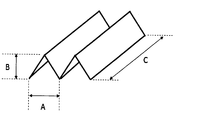
- the form of the supported catalyst will be described more specifically.
- FIG. 1 is a perspective view schematically showing a form of a supported catalyst according to the present invention.
- the supported catalyst has a corrugated plate shape in which the groove is repeated one or more times, the width dimension per groove (indicated by A in the figure), and the number of repetitions of this width dimension.
- Each of (n), height dimension (indicated by B in the figure), and depth (indicated by C in the figure) has a small value, and in that sense, has a small piece shape.
- the width dimension (A) is 2.0 mm or more, preferably 3.0 mm or more, more preferably 4.0 mm or more.
- the width dimension (A) is preferably 100 mm or less, more preferably 50.0 mm or less, still more preferably 25.0 mm or less, and still more preferably 10.0 mm or less.
- the height dimension (B) is 1.0 mm or more, preferably 2.0 mm or more, more preferably 3.0 mm or more. Further, the height dimension (B) is preferably 50.0 mm or less, more preferably 25.0 mm or less, and still more preferably 10.0 mm or less.
- the number of repetitions (n) in the width direction is 1 to 100 times, preferably 1 to 10 times, more preferably 1 to 5 times, and further preferably 2 to 4 times.
- the depth dimension (C) is 3.0 mm or more, preferably 4.0 mm or more, more preferably 5.0 mm or more.
- the depth dimension (C) is preferably 200 mm or less, more preferably 100 mm or less, still more preferably 50.0 mm or less, still more preferably 20.0 mm or less, still more preferably 15.0 mm or less, and even more preferably 10 0.0 mm or less.
- the width dimension (A), the height dimension (B), and the depth dimension (C) may be randomly formed within the above range.
- This supported catalyst is comprised from the glass paper which has a corrugated and small piece form.
- the glass paper is preferably a non-woven fabric using glass fibers.
- a nonwoven fabric is a sheet-like thing in which fibers are intertwined without being woven.
- the fiber amount is preferably 50 to 200 g / m 2 .
- glass paper is an inexpensive material, it is generally preferable if it can be used as a catalyst carrier.
- the commercially available glass paper contains an organic binder, and due to the organic binder, the commercially available glass paper has been known to be a material that is difficult to process. More specifically, when the pressing force against the glass paper is small, a repulsive force due to the organic binder acts to return to the original state. However, when the pressing force against the glass paper is too large, the glass paper is cut. Therefore, when a pressing force is applied to glass paper, the pressing force suitable for it is often limited to a very narrow range.
- the support since the support needs to be processed into a corrugated plate at an initial stage, glass paper containing an inorganic binder as already proposed by the present inventors is used as the support.
- the inorganic binder is added to the carrier together with the catalytically active component for the purpose of fixing the catalytically active component on the carrier.
- the inorganic binder can be processed into glass paper as the carrier. Thus, it also has a function of increasing the mechanical strength.
- an inorganic binder in addition to being able to impart appropriate binding force and shape strength in the step of supporting and corrugating a catalytically active component as described above, it does not significantly impede the performance of the catalytically active component used. This can be freely selected in consideration of this.
- the corrugated and small piece form referred to in the present invention is an effect obtained by using glass paper containing an inorganic binder.
- the supported catalyst of the present invention also has a catalytically active component having a catalytic action, which is supported on the glass paper of the above form.
- the supported catalyst of the present invention can be used for performing various catalytic reactions according to the contained catalytic active component.
- Examples of the supported catalyst of the present invention include methanation reaction, reforming reaction, ammonia decomposition, exhaust gas Used for purification.
- the catalytically active component for realizing these various catalytic reactions is a transition metal having a catalytic action (for example, a Group 4 or 8-10 metal), or a lanthanoid or alkali metal having a catalytic or promoter action. (Group 2), alkaline earth metals (Group 3), base metals (Groups 13 to 15), and oxides of these metals.
- the catalytically active component to be supported may be selected according to the catalytic reaction to be used. For example, for methanation reaction or reforming reaction, catalytic metals for each reaction, nickel (Ni), cobalt (Co ), Platinum (Pt) or the like may be selected.
- nickel (Ni), cobalt (Co ), Platinum (Pt) or the like may be selected.
- ammonia decomposition reaction one of ammonia decomposition catalyst metals such as ruthenium (Ru), cobalt (Co), and nickel (Ni) is used.
- ruthenium (Ru), cobalt (Co), and nickel (Ni) is used.
- the above may be selected, and for the denitration reaction, one or more of titanium (Ti), vanadium (V), and tungsten (W), which are denitration catalyst metals, may be selected.
- the supported catalyst of the present invention is further required to support the catalytically active component on the glass paper as described above, and is required to make the glass paper into a corrugated and small piece form. Containing an inorganic binder.
- an inorganic binder examples include one or more inorganic metal oxides selected from silica, alumina, titania, zirconia, yttria, lanthania, and ceria.
- the supported catalyst used in the catalyst treatment apparatus of the present invention uses a commercially available glass paper as a carrier that is inexpensive but cannot be said to have excellent mechanical strength. By making it contain, it was made excellent in mechanical strength, so that it could be freely molded into a corrugated sheet or cut into small pieces.
- the supported catalyst according to the present invention is configured such that the catalytically active component exists only on the surface of the glass paper. That is, when the supported catalyst according to the present invention is filled in the catalyst processing apparatus, the amount of the catalytic active component used per contact area is significantly larger than that of the conventional catalyst composed of the catalytic active component up to the inside. It becomes possible to decrease. Further, since the casing is not required when the supported catalyst is filled in the catalyst processing apparatus, the catalyst manufacturing cost can be reduced.
- the supported catalyst according to the present invention has a corrugated plate-like and small piece form, these are randomly (irregularly) placed in a reactor (for example, a cylindrical reaction tank) that is a catalyst processing apparatus. Since an appropriate gap is naturally formed when the container is filled, it is possible to avoid an extreme pressure loss during use.
- a reactor for example, a cylindrical reaction tank
- the supported catalyst according to the present invention having such a form that it is cut at a location corresponding to the corrugated groove bottom when cut into small pieces as shown in FIG.
- the supported catalyst according to the present invention since the supported catalyst according to the present invention has a corrugated plate-like shape as its essence, it is cut into a piece by cutting at a location that does not coincide with the bottom of the corrugated plate. Those having such a form are also included in the supported catalyst according to the present invention.
- the supported catalyst according to the present invention is used by filling a catalyst processing apparatus with a large number of corrugated plate-shaped and small piece-shaped supported catalysts, all of which have the same dimensions. You may make it have what a dimension is not constant.
- the supported catalyst according to the present invention is produced by carrying out the following steps. (1) The process of apply
- the above steps are not necessarily performed in the order shown here, and may be appropriately changed.
- the order of firing in step (4) and cutting in step (5) may be reversed.
- coating the slurry containing an inorganic binder and a catalytically active component to flat glass paper The slurry used in this step is mixed with water until the catalyst active ingredient is mixed with water to form an aqueous solution or suspension, and an appropriate amount of a sol containing an inorganic metal oxide as an inorganic binder is added thereto. It is prepared by.
- the catalytically active component referred to in this step means one including the precursor of the catalytically active component.
- the precursor of the catalytically active component is a component that has catalytic activity through a treatment such as heating for supporting the catalytically active component on the carrier, or by further performing a treatment such as a separate reduction treatment. , A compound in a state before such treatment.
- the catalytically active component is selected according to the application of the catalyst to be produced. For example, when preparing a catalyst used in the methanation reaction, at least one selected from nickel, zirconium, and samarium is used.
- the catalytically active component at the time of slurry preparation may be in various forms as long as it can be supported on a carrier, and examples thereof include inorganic or organic salts, oxides, and complexes of metals that become active components.
- the form of an inorganic salt is preferred in that it can be made into an aqueous solution when added to water.
- the inorganic binder is at least one selected from the group consisting of sols containing inorganic metal oxides or organic salts and inorganic salts of these metals. More specifically, the inorganic metal oxide is selected from silica, alumina, titania, zirconia, yttria, lanthania or ceria. The metal organic salt and inorganic salt are at least one selected from metal acetate, oxalate, ammonium carbonate, and nitrate.
- the concentration of the catalytically active component in the slurry may be appropriately determined so that the amount of the catalytically active component per unit surface area of the supported catalyst obtained after the completion of all the steps becomes a desired amount.
- the concentration of the inorganic metal oxide sol or the salt of these metals in the slurry need not be strict and may be an appropriate amount. However, as a result of these concentrations being too low, the inorganic applied to the glass paper. If the amount of the metal-based metal oxide sol or the salt of these metals is too small, the catalytically active component cannot be supported well on the glass paper, and the mechanical strength of the glass paper can be sufficiently improved. On the other hand, if the concentration of the inorganic metal oxide sol or the salt of these metals is too high, it will not be a clear advantage in terms of supporting the catalytically active component and improving the mechanical strength. The consistency may become large and difficult to handle. Therefore, considering these, the range is, for example, 10 to 30% by weight.
- the slurry thus prepared is uniformly applied on a flat glass paper.
- any method known to those skilled in the art may be used as long as it can be uniformly coated on glass paper.
- a so-called soaking method a brush coating method, a spray coating method, a drop coating method, etc. Is mentioned.
- the preheating is performed for the purpose of performing a shaping process and a heating process for evaporating water in the slurry without any stagnation. Specifically, the preheating is performed at 150 to 500 ° C. (equivalent to the surface temperature of the mold). ).
- the glass paper After placing the glass paper on the mold, the glass paper is pressed toward the mold by a pressing jig having a shape corresponding to the corrugated shape of the mold. And it heat-processes with this state maintained. By this heat treatment, moisture present on the surface of the glass paper is removed and thereby dried, but the glass paper is shaped into a corrugated shape by being held in a corrugated shape by the action of the inorganic binder.
- the mold for shaping into a corrugated plate may have a shape in which concave grooves of the same shape are repeated, but has a shape such that the shape of adjacent concave grooves is not the same in detail. May be.
- the heat treatment in this shaping step is performed in a temperature range in which moisture existing on the glass paper surface can be removed.
- the heat treatment is performed at 100 to 500 ° C., but the mold surface temperature is 150 to 500 ° C. It is preferable that When the surface temperature of the mold is less than 150 ° C., moisture removal does not proceed successfully, and as a result, the corrugated plate shape may be poor. On the other hand, when the surface temperature exceeds 500 ° C., the mold is distorted. It can happen. Furthermore, when the time efficiency at the time of manufacture is taken into consideration, the temperature is more preferably in the range of 200 to 500 ° C.
- the heat treatment time may vary depending on the surface temperature of the mold, but is, for example, 5 to 600 seconds.
- the mold used in this step for example, a metal panel having concave grooves in parallel is used.
- the grooves In order to shape the flat glass paper into a corrugated shape based on the parallel grooves, the grooves have a width dimension of 2.0 mm or more and a height dimension of 1.0 mm or more.
- the groove bottom has a radius of curvature of 0.5 to 2 mm in order to avoid tearing the glass paper during the implementation of this process.
- the pressing jig Since the pressing jig is in direct contact with the glass paper from the opposite side of the metal fitting, a part with water repellent finish on this part is used.
- the water repellent process is, for example, a Teflon (registered trademark) process.
- this step results in the form of a supported catalyst in which an inorganic binder and a catalytically active component are supported on the surface of glass paper as a support, in the following description, for simplicity, the one obtained by this step is used. , And referred to as “corrugated supported catalyst”.
- corrugated supported catalyst on the mold is peeled from the mold. Since this corrugated supported catalyst contains an inorganic binder and has improved mechanical strength, it can be easily peeled off without causing damage.
- Step of calcinating corrugated supported catalyst to thermally decompose and remove organic binder contained in supported catalyst In this step, the organic binder contained in the supported catalyst is thermally decomposed and removed by firing the corrugated supported catalyst. Even if heat treatment is performed in this step, the corrugated form is maintained as it is due to the presence of the inorganic binder. Further, the catalytically active component is changed to a desired state by the treatment in this step.
- the desirable state means that the form is basically changed from a salt form to an oxide form as a catalyst precursor, for example, by changing nickel nitrate to nickel oxide.
- the temperature at which the corrugated supported catalyst is calcined in this step is approximately 200 to 550 ° C., although there are differences depending on the use of the catalyst and its components, and the calcining time is approximately the same as that of the temperature. 2 to 10 hours, carried out under air circulation conditions. Considering the time efficiency at the time of manufacture, the temperature is more preferably 200 ° C. or higher. Moreover, when it exceeds 550 degreeC, the catalyst activity of the catalyst active component carry
- the corrugated supported catalyst may be cut into any size, for example, (direction perpendicular to the wave shape) ⁇ (depth dimension (C)): 20 ⁇ 20 (mm).
- the corrugated plate-shaped supported catalyst may be cut so that the cut portion of the corrugated plate-shaped catalyst coincides with the bottom of the corrugated plate groove.
- the corrugated plate of the form shown in FIG. And a small piece of supported catalyst are obtained.
- the cutting in this step may be performed such that the cutting portion does not coincide with the corrugated bottom.
- the supported catalyst may be cut with a constant cutting size so as to have a constant size, but it is cut with a non-constant cutting size so that each supported catalyst has a different size. It may be.
- the mold for shaping into a corrugated plate may have a shape such that the shape of adjacent concave grooves is not the same up to the details, When the corrugated supported catalyst shaped by such a mold is cut, supported catalysts having mutually different adjacent corrugations can be obtained.
- a corrugated and small piece of supported catalyst can be obtained, but the catalytically active component may be further treated according to the target catalytic reaction, for example, reduction treatment is performed.
- This reduction treatment may be performed after performing any of the above steps (1) to (5), but is preferably performed after performing the step (5).
- the catalytically active component in the form of an oxide supported on the glass paper is reduced to a metal form.
- a predetermined catalytic reaction amount including selection of a carrier as a base material from glass paper, which is an inexpensive material, and no need for a casing
- the obtained corrugated plate-like and small piece-like supported catalyst is filled in the catalyst space in the catalyst processing apparatus. Since the filling mode is the same as that of a catalyst processing apparatus configured by filling a conventionally known powdered or granular catalyst, detailed description thereof is omitted.
- the catalyst treatment apparatus of the present invention is filled with a plurality of corrugated and small pieces of supported catalyst at random, and the supported catalyst has a corrugated form, so that it is filled for its use.
- the corrugated plate shape naturally generates a proper three-dimensional void, it is possible to avoid an extreme pressure loss during use.
- the specific surface area in this case is estimated to be approximately 440 m 2 / m 3 , and if the supported catalyst thickness is 1 mm, the porosity is estimated to be approximately 78%.
- the supported catalyst has the above dimensions and thereby has the above specific surface area of 440 m 2 / m 3 and the porosity of 78%
- the porosity at the time of filling in the case of the supported catalyst in the form of the present invention, it is 78% or less. Since it is calculated to be 40%, it is highly possible that the porosity is increased by using the supported catalyst in the form of the present invention, and as a result, there is a high possibility that pressure loss in the packed bed can be suppressed.
- Example 2 In comparison with the porosity at the time of filling, in Example 2 along the present invention, it is 55% or less, and in the case of a cylindrical pellet, it is 40%. The pressure loss in the packed bed can be suppressed.
- Example 1 By sequentially performing the following steps (1) to (10), a supported catalyst for methanation according to the present invention was produced.
- the above-mentioned slurry is applied to a flat glass paper (200 ⁇ 300 mm) containing a fiber amount of 100 g / m 2 and 10% by weight of an acrylic resin organic binder at a coating amount of 6623 g / m 2.
- a flat glass paper 200 ⁇ 300 mm
- corrugation application comprising a corrugated panel made of stainless steel having parallel concave grooves with a width of 7.0 mm, a height of 7.0 mm, and a groove bottom radius of curvature of 1.6 mm on a hot plate.
- a mold 300 ⁇ 300 mm
- a flat glass paper coated with the slurry described in (5) is placed on this mold, pressed by a pressing jig along the concave groove of the mold for 10 seconds, and moisture in the slurry on the glass paper surface is formed.
- a supported catalyst having a corrugated form supported on the surface of glass paper as a support and having a catalytic active component was obtained.
- the corrugated supported catalyst was peeled from the mold. Also during this peeling, the corrugated supported catalyst retains its shape as it is.
- the peeled corrugated supported catalyst was calcined at 500 ° C. for 8 hours under air flow to remove the organic binder component.
- the corrugated supported catalyst after calcination is cut into dimensions of a width of 14.0 mm and a depth of 5.0 mm corresponding to two continuous concave grooves, and corrugated and small pieces for methanation reaction A supported catalyst was obtained.
- the thickness of the obtained supported catalyst was 1.0 mm.
- the obtained corrugated plate-like supported catalyst is packed in a cylindrical reaction tube having an inner diameter of 30 mm with a packing length of 2,500 mm, and the space velocity per catalyst packed bed volume becomes 7,200 h ⁇ 1. Air was circulated at room temperature, and the differential pressure between the inlet and outlet of the packed bed was measured.
- Example 2 A corrugated and small piece supported catalyst according to the present invention is produced in the same manner as in Example 1 except that the surface of the mold in Step (6) in Example 1 is heated to 250 ° C. Thus, a catalyst processing apparatus filled with this was obtained.
- Example 3 A corrugated and small piece supported catalyst according to the present invention is produced in the same manner as in Example 1 except that the surface of the mold in Step (6) in Example 1 is heated to 200 ° C. Thus, a catalyst processing apparatus filled with this was obtained.
- Example 4 A corrugated and small piece supported catalyst according to the present invention is produced in the same manner as in Example 1 except that the surface of the mold in Step (6) in Example 1 is heated to 150 ° C. Thus, a catalyst processing apparatus filled with this was obtained.
- Example 5 A corrugated plate-like supported catalyst according to the present invention is produced in the same manner as in Example 1 except that the surface of the mold in Step (6) in Example 1 is heated to 100 ° C. Thus, a catalyst processing apparatus filled with this was obtained.
- Example 1 A corrugated plate-like supported catalyst according to the present invention was produced in the same manner as in Example 1 except that the surface of the mold in step (6) in Example 1 was used at room temperature. A packed catalyst processor was obtained.
- the time required for peeling is the time when the pressing jig is shaped and then the mold is lifted diagonally from the time when the pressing jig is separated and the corrugated carrier It means the approximate time until the catalyst falls off naturally due to gravity. Moreover, the quality of the corrugated plate shape was determined by whether or not the shape of the catalyst after peeling could be maintained in accordance with the unevenness of the mold used for molding. In Table 1 below, “ ⁇ ” indicates “good”, “ ⁇ ” indicates “defective”, and ⁇ does not reach “defective” but does not reach “good”. It is shown that.
- Example 5 As shown in Table 1 above, in Examples 1 to 5, the corrugated plate shape was good. Further, the lower the mold surface temperature, the longer the time required for peeling. When the mold surface temperature is lowered to 100 ° C. as in Example 5, the time required for peeling is significantly increased. Inefficient drying. In addition, the corrugated shape of the manufactured corrugated supported catalyst was poor under the surface temperature conditions of Example 5. However, these results are considerations from the viewpoint of the efficiency of the production process and the quality of the produced catalyst, and Example 5 also has sufficient catalyst performance. In Comparative Example 1 where the surface temperature of the mold was even lower, the mold was not peeled off and the corrugated shape was not formed.
- Example 6 As the mold in the step (6) in Example 1, a mold having a width dimension (A): 4.0 mm and a height dimension (B): 3.0 mm is used. In the step (8), two continuous grooves are used. A corrugated and small piece of supported catalyst according to the present invention was produced and filled in the same manner as in Example 1 except that it was cut with dimensions corresponding to width 8.0 mm and depth 5.0 mm. A catalyst treatment apparatus was obtained.
- Example 7 As a metal mold of the step (6) in Example 1, a mold having a width dimension (A): 3.0 mm and a height dimension (B): 2.0 mm is used. A corrugated and small piece of supported catalyst according to the present invention was produced and filled in the same manner as in Example 1 except that it was cut to a size of 6.0 mm in width and 5.0 mm in depth corresponding to A catalyst treatment apparatus was obtained.
- Example 8 As a metal mold of the process (6) in Example 1, those having a width dimension (A): 15.0 mm and a height dimension (B): 15.0 mm are used, and in the process (8), two continuous grooves are used. A corrugated and small piece of supported catalyst according to the present invention was produced and filled in the same manner as in Example 1 except that it was cut to a width of 30.0 mm and a depth of 5.0 mm corresponding to A catalyst treatment apparatus was obtained.
- Example 9 As a metal mold of the step (6) in Example 1, a mold having a width dimension (A): 3.0 mm and a height dimension (B): 2.0 mm is used. In the step (8), two continuous grooves are used. A corrugated and small piece of supported catalyst according to the present invention was produced and filled in the same manner as in Example 1 except that it was cut to dimensions of 6.0 mm in width and 3.0 mm in depth corresponding to A catalyst treatment apparatus was obtained.
- Example 10 As a metal mold of the step (6) in Example 1, a mold having a width dimension (A): 2.0 mm and a height dimension (B): 2.0 mm is used, and in the step (8), two continuous grooves are used. A corrugated and small piece of supported catalyst according to the present invention was manufactured and filled in the same manner as in Example 1 except that it was cut with dimensions corresponding to a width of 4.0 mm and a depth of 5.0 mm. A catalyst treatment apparatus was obtained.
- Example 11 As the mold of the step (6) in Example 1, a mold having a width dimension (A): 2.0 mm and a height dimension (B): 1.0 mm is used, and in the step (8), two continuous grooves are used. A corrugated and small piece of supported catalyst according to the present invention was manufactured and filled in the same manner as in Example 1 except that it was cut with dimensions corresponding to a width of 4.0 mm and a depth of 5.0 mm. A catalyst treatment apparatus was obtained.
- the porosity is calculated as (XY) / X after measuring each of the catalyst installation space volume in the reactor as X and the total volume of the loaded supported catalyst pieces as Y. Was measured.
- the differential pressure is a differential pressure between the inlet and the outlet of the packed bed as shown in the first embodiment.
- Example 11 the finer the corrugated shape, the lower the porosity and the greater the pressure loss.
- the porosity is lower than that of Comparative Example 3, which is a case where a cylindrical pellet catalyst is filled, but the pressure loss can be maintained at the same level, and the corrugated plate shape is small. The effect in the form of a piece is obtained.
Landscapes
- Chemical & Material Sciences (AREA)
- Organic Chemistry (AREA)
- Chemical Kinetics & Catalysis (AREA)
- Engineering & Computer Science (AREA)
- Materials Engineering (AREA)
- Physics & Mathematics (AREA)
- Thermal Sciences (AREA)
- General Chemical & Material Sciences (AREA)
- Oil, Petroleum & Natural Gas (AREA)
- Catalysts (AREA)
- Low-Molecular Organic Synthesis Reactions Using Catalysts (AREA)
- Organic Low-Molecular-Weight Compounds And Preparation Thereof (AREA)
Priority Applications (2)
| Application Number | Priority Date | Filing Date | Title |
|---|---|---|---|
| EP16772919.3A EP3278875A4 (en) | 2015-03-31 | 2016-03-30 | Catalyst treatment device and method for manufacturing same |
| US15/562,248 US20180078924A1 (en) | 2015-03-31 | 2016-03-30 | Catalyst treatment device and method for manufacturing same |
Applications Claiming Priority (2)
| Application Number | Priority Date | Filing Date | Title |
|---|---|---|---|
| JP2015073119A JP6574591B2 (ja) | 2015-03-31 | 2015-03-31 | 触媒処理装置およびその製造方法 |
| JP2015-073119 | 2015-03-31 |
Publications (1)
| Publication Number | Publication Date |
|---|---|
| WO2016159038A1 true WO2016159038A1 (ja) | 2016-10-06 |
Family
ID=57005128
Family Applications (1)
| Application Number | Title | Priority Date | Filing Date |
|---|---|---|---|
| PCT/JP2016/060295 Ceased WO2016159038A1 (ja) | 2015-03-31 | 2016-03-30 | 触媒処理装置およびその製造方法 |
Country Status (4)
| Country | Link |
|---|---|
| US (1) | US20180078924A1 (enExample) |
| EP (1) | EP3278875A4 (enExample) |
| JP (1) | JP6574591B2 (enExample) |
| WO (1) | WO2016159038A1 (enExample) |
Families Citing this family (4)
| Publication number | Priority date | Publication date | Assignee | Title |
|---|---|---|---|---|
| JP6867179B2 (ja) * | 2017-02-01 | 2021-04-28 | 日立造船株式会社 | メタン化反応用触媒の製造方法およびメタンの製造方法 |
| KR102805600B1 (ko) * | 2018-07-10 | 2025-05-09 | 닛폰세이테츠 가부시키가이샤 | 탄산 에스터의 제조 방법 및 탄산 에스터 제조용 촉매 구조체 |
| WO2025220482A1 (ja) * | 2024-04-19 | 2025-10-23 | カナデビア株式会社 | 亜酸化窒素分解触媒の製造方法 |
| WO2025220481A1 (ja) * | 2024-04-19 | 2025-10-23 | カナデビア株式会社 | 亜酸化窒素分解触媒の製造方法 |
Citations (6)
| Publication number | Priority date | Publication date | Assignee | Title |
|---|---|---|---|---|
| JPS61249544A (ja) * | 1985-04-26 | 1986-11-06 | Matsushita Electric Ind Co Ltd | 触媒装置 |
| JPH1119511A (ja) * | 1997-06-27 | 1999-01-26 | Babcock Hitachi Kk | 触媒担体の製造方法および製造装置 |
| WO1999024165A1 (en) * | 1997-11-12 | 1999-05-20 | Babcock-Hitachi Kabushiki Kaisha | Exhaust emission control catalyst element, catalyst structure, production method thereof, exhaust emission control apparatus and exhaust emission control method using the apparatus |
| JP2000126615A (ja) * | 1998-10-21 | 2000-05-09 | Babcock Hitachi Kk | 耐摩耗性触媒の製造方法 |
| JP2002119868A (ja) * | 2000-10-17 | 2002-04-23 | Babcock Hitachi Kk | 排ガス浄化用触媒構造体 |
| JP2014117649A (ja) * | 2012-12-17 | 2014-06-30 | Hitachi Zosen Corp | 触媒担持ハニカム構造体を具備する処理装置、およびその製造方法 |
Family Cites Families (9)
| Publication number | Priority date | Publication date | Assignee | Title |
|---|---|---|---|---|
| CH578371A5 (enExample) * | 1973-05-23 | 1976-08-13 | Sulzer Ag | |
| US4065268A (en) * | 1975-09-15 | 1977-12-27 | Betz Erwin C | Non-uniform crimped metal ribbon packed catalyst bed and method using same |
| US4388277A (en) * | 1980-06-06 | 1983-06-14 | United Kingdom Atomic Energy Authority | Catalyst device and method |
| KR100674348B1 (ko) * | 1998-09-09 | 2007-01-24 | 바브콕-히다찌 가부시끼가이샤 | 배가스 정화용 촉매 구조체 및 장치 |
| KR100589513B1 (ko) * | 2005-11-29 | 2006-06-14 | 대영씨엔이(주) | 질소산화물 제거를 위한 선택적 촉매환원반응용 촉매를이용한 코팅제 조성물, 그 선택적 촉매환원반응용 촉매모듈 소자, 및 그 선택적 촉매환원반응용 촉매 모듈 |
| JP6047477B2 (ja) * | 2013-11-18 | 2016-12-21 | 日立造船株式会社 | 脱硝触媒、およびその製造方法 |
| CN106413888A (zh) * | 2014-02-07 | 2017-02-15 | 日立造船株式会社 | 燃烧排气净化用催化剂及燃烧排气的净化方法 |
| KR102375936B1 (ko) * | 2014-03-27 | 2022-03-16 | 히다치 조센 가부시키가이샤 | 벌집구조체와 이것을 사용한 배기가스 정화용 촉매 및 배기가스 정화용 촉매의 제조방법 |
| US20170226914A1 (en) * | 2014-10-15 | 2017-08-10 | Acat Global | Fan fold bonded metal catalyst substrate and method for constructing the same |
-
2015
- 2015-03-31 JP JP2015073119A patent/JP6574591B2/ja not_active Expired - Fee Related
-
2016
- 2016-03-30 EP EP16772919.3A patent/EP3278875A4/en not_active Withdrawn
- 2016-03-30 US US15/562,248 patent/US20180078924A1/en not_active Abandoned
- 2016-03-30 WO PCT/JP2016/060295 patent/WO2016159038A1/ja not_active Ceased
Patent Citations (6)
| Publication number | Priority date | Publication date | Assignee | Title |
|---|---|---|---|---|
| JPS61249544A (ja) * | 1985-04-26 | 1986-11-06 | Matsushita Electric Ind Co Ltd | 触媒装置 |
| JPH1119511A (ja) * | 1997-06-27 | 1999-01-26 | Babcock Hitachi Kk | 触媒担体の製造方法および製造装置 |
| WO1999024165A1 (en) * | 1997-11-12 | 1999-05-20 | Babcock-Hitachi Kabushiki Kaisha | Exhaust emission control catalyst element, catalyst structure, production method thereof, exhaust emission control apparatus and exhaust emission control method using the apparatus |
| JP2000126615A (ja) * | 1998-10-21 | 2000-05-09 | Babcock Hitachi Kk | 耐摩耗性触媒の製造方法 |
| JP2002119868A (ja) * | 2000-10-17 | 2002-04-23 | Babcock Hitachi Kk | 排ガス浄化用触媒構造体 |
| JP2014117649A (ja) * | 2012-12-17 | 2014-06-30 | Hitachi Zosen Corp | 触媒担持ハニカム構造体を具備する処理装置、およびその製造方法 |
Non-Patent Citations (1)
| Title |
|---|
| See also references of EP3278875A4 * |
Also Published As
| Publication number | Publication date |
|---|---|
| EP3278875A4 (en) | 2019-01-02 |
| JP2016190226A (ja) | 2016-11-10 |
| JP6574591B2 (ja) | 2019-09-11 |
| US20180078924A1 (en) | 2018-03-22 |
| EP3278875A1 (en) | 2018-02-07 |
Similar Documents
| Publication | Publication Date | Title |
|---|---|---|
| CN1187113C (zh) | 在负载于筛状结构的催化剂参与下氮的氧化物的转化 | |
| EP2613879B2 (en) | Catalyst manufacturing method | |
| JP5778309B2 (ja) | 水素製造触媒およびそれを用いた水素製造方法 | |
| EP2933020B1 (en) | Processs for producing a treatment device equipped with catalyst-supporting honeycomb structure | |
| JP6574591B2 (ja) | 触媒処理装置およびその製造方法 | |
| JP5103386B2 (ja) | 白金、銅および鉄を含有する改善された高選択酸化触媒 | |
| KR20020047154A (ko) | 일산화탄소의 선택적 산화용 촉매 및 그의 제조 방법 | |
| JP2012005926A (ja) | アンモニア分解触媒及びそれを用いたアンモニア分解方法 | |
| US8889588B2 (en) | High-durability metal foam-supported catalyst for steam carbon dioxide reforming and method for preparing the same | |
| JP2010241675A (ja) | 水素製造方法 | |
| CN106999923A (zh) | 催化剂纤维结构的制备方法 | |
| JP5126762B2 (ja) | 一酸化炭素メタネーション用ハニカム触媒および該触媒の製造方法、該触媒を用いた一酸化炭素のメタネーション方法 | |
| KR101751589B1 (ko) | 상이한 촉매가 코팅된 플레이트를 포함한 열교환형 반응기 | |
| Lu et al. | Microfibrous entrapped ZnO-support sorbents for high contacting efficiency H2S removal from reformate streams in PEMFC applications | |
| US20080187468A1 (en) | Catalyst | |
| JP2016104477A (ja) | 触媒繊維構造体 | |
| Pakdehi et al. | Co-Ni bimetallic catalysts coated on cordierite monoliths for hydrazine decomposition | |
| NL2026371B1 (en) | Catalytic reactor with improved properties | |
| WO2025205989A1 (ja) | メタン製造反応器 | |
| EP4619151A1 (en) | Dry reforming catalyst system | |
| JP5991934B2 (ja) | 水素製造用触媒及びその触媒の製造方法 |
Legal Events
| Date | Code | Title | Description |
|---|---|---|---|
| 121 | Ep: the epo has been informed by wipo that ep was designated in this application |
Ref document number: 16772919 Country of ref document: EP Kind code of ref document: A1 |
|
| WWE | Wipo information: entry into national phase |
Ref document number: 15562248 Country of ref document: US |
|
| NENP | Non-entry into the national phase |
Ref country code: DE |