WO2016158740A1 - ビーム加工装置 - Google Patents
ビーム加工装置 Download PDFInfo
- Publication number
- WO2016158740A1 WO2016158740A1 PCT/JP2016/059604 JP2016059604W WO2016158740A1 WO 2016158740 A1 WO2016158740 A1 WO 2016158740A1 JP 2016059604 W JP2016059604 W JP 2016059604W WO 2016158740 A1 WO2016158740 A1 WO 2016158740A1
- Authority
- WO
- WIPO (PCT)
- Prior art keywords
- processing
- machining
- point
- unit
- data
- Prior art date
- Legal status (The legal status is an assumption and is not a legal conclusion. Google has not performed a legal analysis and makes no representation as to the accuracy of the status listed.)
- Ceased
Links
Images






Classifications
-
- B—PERFORMING OPERATIONS; TRANSPORTING
- B23—MACHINE TOOLS; METAL-WORKING NOT OTHERWISE PROVIDED FOR
- B23K—SOLDERING OR UNSOLDERING; WELDING; CLADDING OR PLATING BY SOLDERING OR WELDING; CUTTING BY APPLYING HEAT LOCALLY, e.g. FLAME CUTTING; WORKING BY LASER BEAM
- B23K26/00—Working by laser beam, e.g. welding, cutting or boring
-
- B—PERFORMING OPERATIONS; TRANSPORTING
- B23—MACHINE TOOLS; METAL-WORKING NOT OTHERWISE PROVIDED FOR
- B23K—SOLDERING OR UNSOLDERING; WELDING; CLADDING OR PLATING BY SOLDERING OR WELDING; CUTTING BY APPLYING HEAT LOCALLY, e.g. FLAME CUTTING; WORKING BY LASER BEAM
- B23K26/00—Working by laser beam, e.g. welding, cutting or boring
- B23K26/08—Devices involving relative movement between laser beam and workpiece
-
- B—PERFORMING OPERATIONS; TRANSPORTING
- B23—MACHINE TOOLS; METAL-WORKING NOT OTHERWISE PROVIDED FOR
- B23K—SOLDERING OR UNSOLDERING; WELDING; CLADDING OR PLATING BY SOLDERING OR WELDING; CUTTING BY APPLYING HEAT LOCALLY, e.g. FLAME CUTTING; WORKING BY LASER BEAM
- B23K26/00—Working by laser beam, e.g. welding, cutting or boring
- B23K26/08—Devices involving relative movement between laser beam and workpiece
- B23K26/082—Scanning systems, i.e. devices involving movement of the laser beam relative to the laser head
Definitions
- the present invention relates to a beam processing apparatus for processing a workpiece by irradiating an energy beam.
- the workpiece which is a workpiece, is cut or drilled using a pulsed laser beam emitted from a YAG laser having a Q switch.
- a laser processing apparatus that performs such processing is known.
- Patent Document 1 The invention described in Patent Document 1 is known as an invention related to such a beam processing apparatus.
- the laser processing apparatus described in Patent Document 1 sets a workpiece on an XY table, and moves each pulse-shaped laser to the workpiece while moving the workpiece in a direction crossing the irradiation direction of the pulse-shaped laser light for each processing element. It is configured to continuously irradiate light.
- Patent Document 1 The laser light irradiation in Patent Document 1 is performed so as to maintain a constant pitch between the processing points. And in patent document 1, by changing the pitch between each process point according to the length of a process element, the length of a process element and the pitch between each process point can be made to respond
- the processing of the processing element is realized with a length of.
- the laser processing apparatus described in Patent Document 1 adjusts the pitch between the processing points in accordance with the length of the processing element.
- the pitch between the machining points in one machining element is different from the pitch between the machining points in the other machining elements.
- the energy density per unit distance for one machining element and the energy per unit distance for other machining elements The density will be different. That is, in Patent Document 1, the energy density per unit distance may be different for each machining element constituting a certain machining content, which leads to a reduction in machining quality as a whole machining content.
- the present disclosure has been made in view of the above problems, and relates to a beam processing apparatus that processes a workpiece by irradiating a beam, and performs desired processing based on the processing content while maintaining an energy density per unit distance. It is an object to provide an executable beam processing apparatus.
- a beam processing apparatus includes an irradiation position moving unit that relatively moves an irradiation position of the beam emitted from the beam emitting unit on the workpiece, and a beam from the beam emitting unit.
- a machining data acquisition unit that acquires machining data indicating machining content using a beam
- a machining condition acquisition unit that acquires machining conditions related to machining of the workpiece using the beam
- a machining condition acquired by the machining condition acquisition unit And an output condition determination unit for determining an emission condition of the beam emitted from the beam emission unit, and a line segment constituting the processing content of the processing data based on the processing data acquired by the processing data acquisition unit
- the processing point arrangement portion for arranging the processing points irradiated with the beam for each predetermined pitch, the processing data Irradiation of the beam with respect to the processing point of the beam at the portion where the pitch is changed by the processing point changing unit and the processing point changing unit that changes the pitch of a part of the processing point arranged by the processing point arranging unit
- an emission condition adjusting unit that adjusts the emission condition determined by the emission condition determining unit so that the energy density per unit distance given by is the same as the energy density before the pitch change
- the beam processing apparatus includes a beam extraction unit, an irradiation position moving unit, a processing data acquisition unit, a processing condition acquisition unit, an extraction condition determination unit, a processing point arrangement unit, a processing point change unit, and an extraction condition adjustment.
- the workpiece is processed by the beam according to the processing content of the processing data by relatively moving the irradiation position of the beam emitted from the beam emitting portion on the workpiece by the irradiation position moving portion. Can be done.
- the said beam processing apparatus changes the pitch of a part of the said processing point arrange
- the beam processing apparatus adjusts the emission condition determined by the emission condition determination unit by the emission condition adjustment unit, so that the beam processing point in the portion where the pitch is changed by the processing point change unit.
- the energy density per unit distance given by the beam irradiation can be changed to be the same as before the pitch change, and the energy density per unit distance can be maintained. That is, according to the beam processing apparatus, desired processing according to the processing content of the processing data can be realized, and at the same time, deterioration of processing quality due to change in the pitch of processing points can be suppressed.
- a beam processing apparatus is the beam processing apparatus according to claim 1, wherein the processing point arrangement unit sets a reference point on a line segment constituting the processing content of the processing data.
- the processing points are arranged at predetermined pitches based on the reference point, and the processing point changing unit changes the pitch of the processing points in a part of the line segment according to the processing content of the processing data. It is characterized by doing.
- the processing point arrangement unit arranges the processing points at predetermined pitches with reference to a reference point set on a line segment constituting the processing content of the processing data, and the processing points
- the changing unit changes the pitch of the machining point in a part of the line segment according to the machining content of the machining data so that the energy density per unit distance is the same as before the pitch change. It is possible to suppress the degradation of machining quality due to the change of the pitch of the machining point, and to clarify the area where the pitch is not changed near the reference point and the part of the area where the pitch is changed, and control the influence on the machining. it can.
- a beam processing apparatus is the beam processing apparatus according to claim 1 or 2, wherein the processing point arrangement unit is provided at one end of a line segment constituting the processing content of the processing data.
- a reference point is set, the processing points are arranged at predetermined pitches with reference to the reference point, and the processing point changing unit sets the pitch of the processing points on the other end side of the line segment to the processing data. It is characterized by changing according to the processing content.
- the processing point arrangement unit sets a reference point at one end of a line segment constituting the processing content of the processing data, and sets the processing point at a predetermined pitch with reference to the reference point.
- the processing point changing unit changes the pitch of the processing point on the other end side of the line segment according to the processing content of the processing data, and the energy density per unit distance is the same as before the pitch change. Therefore, it is possible to suppress the degradation of machining quality due to the change in the pitch of the machining point, and to clarify the one end area where the pitch is not changed and the other end area where the pitch is changed, thereby affecting the machining. Can be controlled.
- a beam processing apparatus is the beam processing apparatus according to any one of claims 1 to 3, wherein the emission condition adjusting unit is configured to adjust the processing point by the processing point arranging unit. In proportion to the ratio of the pitch and the pitch of the machining point changed by the machining point changing unit, the energy density per unit distance given to the part where the pitch is changed is the same as before the pitch change. The emission condition is adjusted.
- the emission condition adjustment unit is proportional to the ratio of the processing point pitch by the processing point arrangement unit and the processing point pitch changed by the processing point change unit, In order to adjust the emission conditions so that the energy density per unit distance given to the part where the pitch is changed is the same as before the pitch change, even if there is a part where the pitch is changed, The energy density per unit distance can be maintained.
- a beam processing apparatus is the beam processing apparatus according to any one of claims 1 to 4, wherein the emission condition adjusting unit is configured such that an energy density per unit distance is a pitch change. The peak energy of the beam as the emission condition is adjusted according to the changed pitch so as to be the same as before.
- the beam processing apparatus by adjusting the peak energy of the beam as the emission condition by the emission condition adjustment unit, the energy density per unit distance is changed before the pitch change according to the changed pitch.
- the energy density per unit distance in the line segment can be reliably maintained.
- a beam processing apparatus is the beam processing apparatus according to any one of claims 1 to 5, wherein the beam emitting unit emits a pulse laser as the beam, The emission condition adjusting unit adjusts the number of pulses of the pulse laser as the emission condition according to the changed pitch so that the energy density per unit distance is the same as before the pitch change. To do.
- the energy density per unit distance is changed by adjusting the number of pulses of the pulse laser emitted from the beam emitting unit as the emitting condition by the emitting condition adjusting unit.
- the energy density before the pitch change can be made the same, and the energy density per unit distance in the line segment can be reliably maintained.
- a beam processing apparatus is the beam processing apparatus according to any one of claims 1 to 6, wherein the beam emitting unit emits a pulse laser as the beam, The emission condition adjustment unit adjusts the frequency of the pulse laser as the emission condition according to the changed pitch so that the energy density per unit distance is the same as before the pitch change. .
- the energy density per unit distance is changed by adjusting the frequency of the pulse laser emitted from the beam emitting unit as the emitting condition by the emitting condition adjusting unit. It can be made the same as the energy density before the pitch change according to the pitch, and the energy density per unit distance in the line segment can be reliably maintained.
- a beam processing apparatus is the beam processing apparatus according to any one of claims 1 to 7, wherein a processing point in one processing element constituting the processing content of the processing data, A determination unit that determines whether or not a processing point in another processing element constituting the processing content of the processing data is located within a predetermined range, and a processing point in the one processing element by the determination unit, When it is determined that a machining point in the other machining element is within a predetermined range, emission of the beam to one of the machining point in the one machining element and the machining point in the other machining element is stopped. And a processing point exclusion section.
- the beam processing apparatus includes a determination unit and a processing point exclusion unit, and the determination unit determines that a processing point in the one processing element and a processing point in the other processing element are within a predetermined range. In this case, the emission of the beam to one of the machining point in the one machining element and the machining point in the other machining element is stopped.
- the machining point in one machining element and the machining point in another machining element are within the predetermined range, if both of the machining points are irradiated with a beam, the workpiece is damaged too much by the beam irradiation. In some cases, the processing quality may be degraded.
- the beam processing apparatus since the emission of the beam to one of the processing point in the one processing element and the processing point in the other processing element is stopped, the beam is excessively applied to the workpiece. Damage can be suppressed, and deterioration in processing quality can be suppressed. be able to.
- a beam processing apparatus is the beam processing apparatus according to any one of claims 1 to 8, and is included in each processing point arranged for the processing content of the processing data.
- Each machining point arranged with respect to the machining content of the machining data so that the distance between the one machining point to be machined and the machining point machined next to the one machining point is equal to or greater than a reference distance. It has the processing order determination part which determines the processing order of this.
- the beam processing apparatus has a processing order determination unit, and is processed after the one processing point included in each processing point arranged for the processing content of the processing data and the one processing point.
- the processing order of the processing points arranged for the processing content of the processing data is determined so that the distance between the processing points is equal to or greater than the reference distance.
- the processing data is processed so that the distance between one processing point and the processing point processed next to the one processing point is equal to or greater than a reference distance.
- processing based on the processing data can be executed while minimizing damage to the workpiece.
- the beam processing apparatus is the beam processing apparatus according to claim 9, wherein the processing condition acquisition unit acquires information on a configuration of the workpiece as the processing condition, and the processing condition It has a reference distance setting part which sets the reference distance based on information about composition of the work acquired by the acquisition part.
- the beam processing apparatus includes a reference distance setting unit, and sets the reference distance based on information (for example, thickness, material, etc.) on the workpiece configuration acquired by the processing condition acquisition unit.
- information for example, thickness, material, etc.
- the reference distance is used as a reference for determining the processing order in the processing order determination unit, according to the beam processing apparatus, the processing order of each processing point is determined according to the information regarding the configuration of the workpiece. Therefore, machining based on the machining data can be executed while minimizing damage to the workpiece in an appropriate manner according to the configuration of the workpiece.
- a beam processing apparatus is the beam processing apparatus according to claim 9 or 10, wherein an arbitrary processing point is selected from the processing points arranged for the processing content of the processing data. And a machining order setting unit that accepts a machining order setting for the selected machining point, and the machining order determination unit includes the machining points arranged for the machining content of the machining data.
- the processing order of the processing points in the processing content of the processing data is determined except for the processing points and processing orders for which the processing order is set by the processing order setting unit.
- the beam processing apparatus includes a processing order setting unit that receives selection of an arbitrary processing point from processing points arranged for processing contents of the processing data and receives setting of a processing order for the selected processing point.
- the processing order determination unit except for the processing points and processing orders in which the processing order is set by the processing order setting unit, among the processing points arranged for the processing content of the processing data, The processing order of the processing points in the processing content is determined. That is, according to the beam processing apparatus, the processing points set by the processing order setting unit can be set in the processing order desired by the user, so that the processing desired by the user can be realized. Further, since the processing order is determined by the processing order determination unit except for the processing points set by the processing order setting unit, the beam processing apparatus can minimize damage to the workpiece.
- a beam processing apparatus is the beam processing apparatus according to any one of claims 9 to 11, wherein two consecutive beams are processed in the processing order determined by the processing order determination unit.
- a cooling period setting unit that sets a cooling period for cooling the workpiece when the beam irradiation position moves between the two consecutive machining points.
- the beam processing apparatus includes a determination unit and a cooling period setting unit, and when the determination unit determines that the distance between two processing points continuous in the processing order is less than a predetermined distance, A cooling period for cooling the workpiece is set when the beam irradiation position moves between the two consecutive machining points. That is, at two consecutive machining points, when the influence of heat caused by beam irradiation on the previous machining point can affect the machining on the next machining point, the beam machining apparatus provides a cooling period. In addition, since the workpiece can be cooled, damage to the workpiece can be suppressed, and deterioration in machining quality can be suppressed.
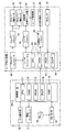
- a beam processing apparatus according to the present invention is embodied as a laser processing system 100 including a laser processing apparatus 1 capable of performing cutting using a pulse laser L as a beam
- the cutting process here includes not only a process of simply dividing the object to be processed but also a wide range of processes by partially removing the object to be processed, such as a trimming process and a drilling process.
- the laser processing system 100 includes a laser processing apparatus 1 and a PC 7, and controls the laser processing apparatus 1 in accordance with the processing data DW created by the PC 7, so that the surface of the processing object (for example, the workpiece W).
- the laser beam is configured to be cut by two-dimensionally scanning a pulse laser L as a beam.
- the laser processing apparatus 1 includes a laser processing apparatus main body 2, a laser controller 5, and a power supply unit 6.
- the laser processing apparatus main body 2 irradiates a processing target (for example, a workpiece W) with a pulse laser L, performs two-dimensional scanning with the pulse laser L, and cuts the processing target.
- the laser controller 5 is configured by a computer, is connected to the PC 7 so as to be capable of bidirectional communication, and is electrically connected to the laser processing apparatus main body 2 and the power supply unit 6.
- the PC 7 is configured by a personal computer, and is used when creating machining data DW when cutting a workpiece, setting control parameters according to machining conditions, and the like.
- the laser controller 5 drives and controls the laser processing apparatus main body 2 and the power supply unit 6 based on the processing data DW transmitted from the PC 7, control parameters, various instruction information, and the like.
- the workpiece W corresponds to an example of the workpiece W that is a workpiece.
- FIG. 1 shows schematic structure of the laser processing system 100 and the laser processing apparatus 1, the laser processing apparatus main-body part 2 is shown typically. Therefore, a specific configuration of the laser processing apparatus main body 2 will be described later.
- the left direction, the right direction, the upper direction, and the lower direction in FIG. 1 are the front direction, the rear direction, the upper direction, and the lower direction, respectively. Therefore, the emission direction of the pulse laser L of the laser oscillator 21 is the forward direction.
- the direction perpendicular to the main body base 11 and the pulse laser L is the vertical direction.
- the direction orthogonal to the up-down direction and the front-rear direction of the laser processing apparatus main body 2 is the left-right direction of the laser processing apparatus main body 2.
- the laser processing apparatus main body 2 includes a laser head 3 (see FIG. 2) that emits the pulse laser L and the visible laser light M coaxially from the f ⁇ lens 20, and a substantially box body on which the laser head 3 is fixed to the upper surface. And a cylindrical processing container (not shown).
- the laser head unit 3 includes a main body base 11, a laser oscillation unit 12 that emits a pulse laser L, an optical shutter unit 13, an optical damper 14, a half mirror 15, and a guide light unit 16. And a reflection mirror 17, an optical sensor 18, a galvano scanner 19, an f ⁇ lens 20, and the like, and is covered with a substantially rectangular parallelepiped housing cover (not shown).
- the laser oscillation unit 12 includes a laser oscillator 21, a beam expander 22, and a mounting base 23.
- the laser oscillator 21 has a fiber connector, a condenser lens, a reflecting mirror, a laser medium, a passive Q switch, an output coupler, and a window in a casing.
- An optical fiber F is connected to the fiber connector, and pumping light emitted from the pumping semiconductor laser unit 40 constituting the power supply unit 6 enters through the optical fiber F.
- the condensing lens condenses the excitation light incident from the fiber connector.
- the reflecting mirror transmits the excitation light collected by the condenser lens and reflects the laser light emitted from the laser medium with high efficiency.
- the laser medium is excited by excitation light emitted from the excitation semiconductor laser unit 40 and oscillates laser light.
- the laser medium include a neodymium-added gadolinium vanadate (Nd: GdVO4) crystal to which neodymium (Nd) is added as a laser active ion, a neodymium-added yttrium vanadate (Nd: YVO4) crystal, and a neodymium-added yttrium aluminum garnet. (Nd: YAG) crystal or the like can be used.
- the passive Q switch is a crystal having a property that the transmittance increases when the light energy stored inside exceeds a certain value. Therefore, the passive Q switch functions as a Q switch that oscillates the laser beam oscillated by the laser medium as a pulsed pulse laser L.
- a chrome-added YAG (Cr: YAG) crystal, Cr: MgSiO4 crystal, or the like can be used as the passive Q switch.
- the output coupler constitutes a reflecting mirror and a laser resonator.
- the output coupler is, for example, a partial reflecting mirror constituted by a concave mirror whose surface is coated with a dielectric multilayer film, and has a reflectance of 80% to 95% at a wavelength of 1064 nm.
- the window is made of synthetic quartz or the like, and transmits the laser light emitted from the output coupler to the outside. Therefore, the laser oscillator 21 oscillates a pulse laser through the passive Q switch, and outputs a pulse laser L as a laser beam for cutting the workpiece W.
- the beam expander 22 changes the beam diameter of the pulse laser L and is provided coaxially with the laser oscillator 21.
- the mounting base 23 is attached so that the laser oscillator 21 can adjust the optical axis of the pulse laser L, and is fixed to the upper surface on the rear side of the main body base 11 in the front-rear direction by a mounting screw 25.
- the optical shutter unit 13 includes a shutter motor 26 and a flat shutter 27.
- the shutter motor 26 is composed of a stepping motor or the like.
- the shutter 27 is attached to the motor shaft of the shutter motor 26 and rotates coaxially.
- the shutter 27 rotates to a position that blocks the optical path of the pulse laser L emitted from the beam expander 22
- the shutter 27 reflects the pulse laser L to the optical damper 14 provided in the right direction with respect to the optical shutter unit 13.
- the shutter 27 rotates so as not to be positioned on the optical path of the pulse laser L emitted from the beam expander 22
- the pulse laser L emitted from the beam expander 22 is placed on the front side of the optical shutter unit 13. It enters the arranged half mirror 15.
- the optical damper 14 absorbs the pulse laser L reflected by the shutter 27.
- the heat generated by the optical damper 14 is thermally conducted to the main body base 11 and cooled.
- the half mirror 15 is arranged so as to form an angle of 45 degrees obliquely in the lower left direction with respect to the optical path of the pulse laser L.
- the half mirror 15 transmits almost all of the pulse laser L incident from the rear side.
- the half mirror 15 reflects a part of the pulse laser L incident from the rear side to the reflection mirror 17 at a reflection angle of 45 degrees.
- the reflection mirror 17 is arranged in the left direction with respect to a substantially central position of the rear side surface on which the pulse laser L of the half mirror 15 is incident.
- the guide light unit 16 includes, for example, a visible semiconductor laser 28 that emits red laser light as visible laser light, and a lens group (not shown) that converges the visible laser light M emitted from the visible semiconductor laser 28 into parallel light. It consists of and.
- the visible laser light M has a wavelength different from that of the pulse laser L emitted from the laser oscillator 21.
- the guide light unit 16 is arranged in the right direction with respect to a substantially central position where the pulse laser L of the half mirror 15 is emitted.
- the visible laser beam M is incident at an incident angle of 45 degrees with respect to the reflection surface corresponding to the front side surface of the half mirror 15 at a substantially central position where the pulse laser L of the half mirror 15 is emitted, and reflected by 45 degrees. Reflected on the optical path of the pulsed laser L at the corners. That is, the visible semiconductor laser 28 emits visible laser light M onto the optical path of the pulse laser L.
- the reflection mirror 17 is disposed so as to form an angle of 45 degrees obliquely in the lower left direction with respect to the front-rear direction parallel to the optical path of the pulse laser L.
- the reflection mirror 17 reflects the pulse laser L reflected on the rear side surface of the half mirror 15. A part of the light is incident at an incident angle of 45 degrees with respect to a substantially central position of the reflecting surface.
- the reflection mirror 17 reflects the pulse laser L incident on the reflection surface at an incident angle of 45 degrees toward the front side at a reflection angle of 45 degrees.
- the optical sensor 18 is composed of a photodiode or the like that detects the light emission intensity of the pulse laser L, and is disposed in the front direction in FIG. 2 with respect to a substantially central position where the pulse laser L of the reflection mirror 17 is reflected. .
- the optical sensor 18 receives the pulse laser L reflected by the reflection mirror 17 and detects the output intensity of the incident pulse laser L. Therefore, the intensity of the pulse laser L output from the laser oscillator 21 via the optical sensor 18 can be detected.
- the galvano scanner 19 is attached to the upper side of a through hole 29 formed at the front end of the main body base 11, and the pulse laser L emitted from the laser oscillation unit 12 and the visible laser light M reflected by the half mirror 15 Is two-dimensionally scanned downward.
- the galvano scanner 19 includes a galvano X-axis motor 31, a galvano Y-axis motor 32, and a main body 33.
- the galvano X-axis motor 31 and the galvano Y-axis motor 32 are configured such that their motor axes are orthogonal to each other. Are attached to the main body 33 by being fitted and held in the respective mounting holes from the outside.
- the two-dimensional scanning direction is a front-rear direction (X direction) and a left-right direction (Y direction).
- the f ⁇ lens 20 concentrically condenses the pulse laser L and the visible laser light M that are two-dimensionally scanned by the galvano scanner 19 on the surface of a workpiece (work W or the like) disposed below.
- the f ⁇ lens 20 corrects the focal point where the pulse laser L, the visible laser beam M, and the like are converged to a flat focal plane, and the scanning speed of the pulse laser L and the visible laser beam M is constant. To do. Therefore, by controlling the rotation of the galvano X-axis motor 31 and the galvano Y-axis motor 32, the pulse laser L and the visible laser light M are moved in the front-rear direction (X direction) and left and right in a desired processing pattern on the surface of the workpiece W. Two-dimensional scanning is performed in the direction (Y direction).
- the power supply unit 6 includes a pumping semiconductor laser unit 40, a laser driver 51, a power supply unit 52, and a cooling unit 53 in a casing 55.
- the power supply unit 52 supplies a driving current for driving the pumping semiconductor laser unit 40 to the pumping semiconductor laser unit 40 via the laser driver 51.
- the laser driver 51 drives the pumping semiconductor laser unit 40 on and off with a direct current.
- the pumping semiconductor laser unit 40 is optically connected to the laser oscillator 21 by an optical fiber F.
- the pumping semiconductor laser unit 40 emits pumping light, which is laser light having an output wavelength proportional to the current value exceeding the threshold current for generating laser light, with respect to the pulsed driving current input from the laser driver 51.
- the light is emitted into the optical fiber F. Therefore, the pumping light from the pumping semiconductor laser unit 40 is incident on the laser oscillator 21 via the optical fiber F.
- a bar-type semiconductor laser using GaAs can be used for the pumping semiconductor laser unit 40.
- the cooling unit 53 is a unit for adjusting the power supply unit 52 and the pumping semiconductor laser unit 40 within a predetermined temperature range.
- the cooling unit 53 is cooled by an electronic cooling method, so that the temperature of the pumping semiconductor laser unit 40 is increased. Control is performed, and the oscillation wavelength of the pumping semiconductor laser unit 40 is finely adjusted.
- the cooling unit 53 may be a water cooling type cooling unit, an air cooling type cooling unit, or the like.
- the laser processing apparatus 1 includes a laser controller 5 that controls the entire laser processing apparatus 1, a laser driver 51, a galvano controller 56, a galvano driver 57, a visible light laser driver 58, and the like. Configured. A laser driver 51, a galvano controller 56, an optical sensor 18, a visible light laser driver 58, and the like are electrically connected to the laser controller 5.
- the laser controller 5 includes an arithmetic unit that performs overall control of the laser processing apparatus 1, a CPU 61 as a control unit, a RAM 62, a ROM 63, a timer 64 that measures time, and the like.
- the CPU 61, RAM 62, ROM 63, and timer 64 are connected to each other by a bus line (not shown), and exchange data with each other.
- the RAM 62 is for temporarily storing various calculation results calculated by the CPU 61, XY coordinate data of each processing point D in the processing data DW, and the like.
- the ROM 63 stores various programs. Based on the machining data DW transmitted from the PC 7, the XY coordinate data of each machining point D constituting the machining element DC is calculated and stored in the RAM 62. The various programs are stored.
- the ROM 63 stores, for each font type, data such as the font start point, end point, focus, and curvature of each character composed of straight lines and elliptical arcs.
- the CPU 61 performs various calculations and controls based on various control programs stored in the ROM 63. For example, the CPU 61 outputs XY coordinate data, galvano scanning speed information, and the like of each machining point D in the machining element DC to the galvano controller 56 based on the machining data DW input from the PC 7. The CPU 61 also supplies the laser driver 51 with information such as drive current supply control to the pumping semiconductor laser unit 40 input from the PC 7, pumping light output from the pumping semiconductor laser unit 40, and pumping light output period. Output. Further, the CPU 61 outputs XY coordinate data of each processing point D, a control signal for instructing ON / OFF of the galvano scanner 19, and the like to the galvano controller 56.
- the laser driver 51 is based on the control parameters (for example, current value of driving current, pumping light output, pumping light output period, etc.) regarding the pumping semiconductor laser unit 40 input from the laser controller 5. 40 is driven and controlled. Specifically, the laser driver 51 generates a pulsed drive current based on a control parameter related to the current value of the drive current input from the laser controller 5 and supplies the pulsed drive current to the pumping semiconductor laser unit 40. As a result, the pumping semiconductor laser unit 40 supplies pumping light having an intensity corresponding to the current value of the drive current into the optical fiber F during a predetermined supply period.
- control parameters for example, current value of driving current, pumping light output, pumping light output period, etc.
- the galvano controller 56 calculates drive angles, rotation speeds, and the like of the galvano X-axis motor 31 and the galvano Y-axis motor 32 based on the XY coordinate data, galvano scanning speed information, and the like of each processing point D input from the laser controller 5. Then, motor drive information representing the drive angle and rotation speed is output to the galvano driver 57.
- the galvano driver 57 drives and controls the galvano X-axis motor 31 and the galvano Y-axis motor 32 based on the motor drive information representing the drive angle and rotation speed input from the galvano controller 56, and two-dimensionally scans the pulse laser L. To do.
- the visible light laser driver 58 controls the guide light unit 16 including the visible semiconductor laser 28 based on the control signal output from the laser controller 5. For example, the visible light laser driver 58 is emitted from the visible semiconductor laser 28 based on the control signal. The light emission timing and the light amount of the visible laser beam M are controlled.
- a PC 7 is connected to the laser controller 5 so as to be capable of two-way communication.
- Processing data DW indicating processing contents transmitted from the PC 7, control parameters of the laser processing apparatus main body 2. It is configured to be able to receive various instruction information from the user.
- the PC 7 includes a control unit 70 that controls the entire PC 7, an input operation unit 76 composed of a mouse, a keyboard, and the like, a liquid crystal display 77, various data, programs, and the like for the CD-ROM 79. It consists of a CD-R / W78 for writing and reading.
- the control unit 70 controls the entire PC 7 and measures the CPU 71, the RAM 72, the ROM 73, and the time as a calculation device and a control device for controlling the entire laser processing system 100 via the laser controller 5.
- a timer 74 and an HDD 75 are provided.
- the CPU 71, the RAM 72, the ROM 73, and the timer 74 are connected to each other via a bus line (not shown) to exchange data with each other.
- the CPU 71 and the HDD 75 are connected via an input / output interface (not shown), and exchange data with each other.
- the RAM 72 is for temporarily storing various calculation results and the like calculated by the CPU 71.
- the ROM 73 stores various control programs and data tables.
- the HDD 75 is a storage device for storing various application software programs and various data files.
- the HDD 75 is a machining data processing program (see FIG. 4) and various subroutines (see FIG. 4) for creating the machining data DW. 6, 9 and 12) and various data tables such as a reference distance setting table (see FIG. 11) which is referred to when setting a reference distance which will be described later is stored.
- the CD-R / W 78 reads or writes data groups such as application programs and various data tables from the CD-ROM 79. That is, the PC 7 reads the machining data processing program and subroutine (see FIG. 4 and the like) and the reference distance setting table (see FIG. 11) from the CD-ROM 79 via the CD-R / W 78 and stores them in the HDD 75.
- the machining data processing program and subroutine (see FIG. 4 and the like) and the reference distance setting table (see FIG. 11) may be stored in the ROM 73 or may be read from a storage medium such as the CD-ROM 79. . Alternatively, it may be downloaded via a network (not shown) such as the Internet.
- the PC 7 is electrically connected to an input operation unit 76 composed of a mouse, a keyboard, etc., and a liquid crystal display 77, etc. via an input / output interface (not shown). Accordingly, the PC 7 uses the input operation unit 76 and the liquid crystal display 77 to set work information (for example, the material of the work W, the thickness of the work W, etc.) and to give an instruction to start laser processing. It is used when performing etc.
- work information for example, the material of the work W, the thickness of the work W, etc.
- the machining data processing program is an application program that is executed when creating machining data, and is executed by the CPU 71.
- the CPU 71 first executes machining data generation processing to generate machining data DW indicating the content to be cut by cutting (S1). After storing the processed data DW in the RAM 72, the CPU 71 shifts the process to S2.
- the processing data DW includes contents to be cut by the pulse laser L with respect to the surface of the workpiece W, and control parameters such as a processing order when cutting according to the cutting contents.
- the cutting content in the machining data DW is expressed by combining one or a plurality of machining elements DC.
- One processing element DC shows the content which can be cut
- the user can set the cutting content in the machining data DW by appropriately arranging and combining desired machining elements DC by operating the input operation unit 76 of the PC 7 or the like.
- the CPU 71 arranges a plurality of machining points D according to the cutting contents in order to express the cutting contents of the machining data DW by executing the machining point setting process.
- the CPU 71 reads out and executes a processing point setting process program (see FIG. 6) from the HDD 75.
- the CPU 71 arranges a large number of machining points D at a predetermined reference pitch P for each machining element DC in the machining data DW. For example, in the case of the machining data DW shown in FIG. 5, the CPU 71 executes the machining point arrangement process (S11), thereby arranging a plurality of machining points D for each machining element DC in the machining data DW (see FIG. 7). ).
- the processing point arrangement processing (S11) will be specifically described.
- the CPU 71 sets one processing element DC in the processing data DW as a processing target, sets a reference point on the line of the processing element DC, The processing points D are arranged for each predetermined reference pitch P with reference to the reference point.
- the CPU 71 sets a reference point at one end of the machining element DC, and arranges the machining points D for each reference pitch P with the reference point as a reference (see FIG. 8A).
- the CPU 71 can set the energy density E per unit distance.
- CPU71 transfers a process to S12.
- the CPU 71 When proceeding to S12, the CPU 71 extracts one machining element DC as a processing target from the machining data DW in which the machining points D are arranged for each reference pitch P by the machining point arrangement process (S11). After extracting one machining element DC as a processing target, the CPU 71 shifts the processing to S13.
- the CPU 71 shifts the process to S14.
- the machining element length LC of the machining element DC is N times the reference pitch P (S13: NO)
- the CPU 71 shifts the process to S16.
- the CPU 71 executes a machining point adjustment process on the machining element DC extracted as a processing target.
- the processing element DC which is the processing mode in this case is in a state in which the processing element length LC is not N times the reference pitch P and a deviation occurs. Accordingly, in the processing point adjustment process (S14), the CPU 71 performs processing point D on the end side at the end of the processing element DC where the end of the processing element DC is shifted from the position of the processing point D. Is adjusted to coincide with the end of the machining element DC.
- processing point adjustment processing (S14)
- a machining element DC that forms a straight line is extracted as a processing target from the machining data DW shown in FIGS. 5 and 7 is used.
- FIG. 8A in the processing point arrangement process (S11), a reference point is set at one end located on the left side in FIG. A processing point D is arranged for each pitch P. At this time, an energy density E per unit distance is set corresponding to a predetermined reference pitch P.
- the machining element disposed at every other pitch (on the right side in FIG. 8) of the machining element length LC of the machining element DC and the reference pitch P. There is a shift in the position of the point D.
- the machining point adjustment process (S14) is executed for the linear machining element DC to be processed.
- the other end side (right side in FIG. 8) of the machining element DC in a straight line shape the other end portion so that the position of the machining point D on the other end side coincides with the end portion of the machining element DC.
- the reference pitch P between the processing points D on the side is adjusted to the adjustment pitch PA (see FIG. 8B).
- the some processing point D in the said processing element DC is arrange
- the machining point adjustment process (S14) is performed on the machining element DC extracted as the processing target, and the machining point D on the other end side of the machining element DC is changed to the machining element length LC of the machining element DC.
- the CPU 71 stores information on the adjustment pitch PA in the RAM 72, and proceeds to S15.
- the CPU 71 executes an energy density adjustment process to adjust the energy density per unit distance for the portion adjusted from the reference pitch P to the adjustment pitch PA. Specifically, the CPU 71 sets the ratio of the adjustment pitch PA to the reference pitch P (that is, the adjustment pitch PA / reference pitch P) to the energy density E per unit distance for the portion adjusted from the reference pitch P to the adjustment pitch PA. ) To calculate and set the adjustment energy density EA per unit distance. By setting in this way, the energy density per unit distance with respect to the adjustment pitch PA can be adjusted to be the same as the energy density E before the pitch adjustment.
- the CPU 71 sets the number of pulses of the pulse laser L emitted from the laser oscillation unit 12 by increasing or decreasing.
- the CPU 71 sets the energy density per unit distance (adjusted energy density EA) as the energy density E before the pitch change as the emission condition of the pulse laser L for the portion adjusted from the reference pitch P to the adjusted pitch PA. Further, the number of pulses of the pulse laser as the emission condition is set and defined in the machining data DW.
- the CPU 71 shifts the process to S16.
- the CPU 71 determines whether or not the processing (S12 to S15) for all the machining elements DC included in the machining data DW has been completed.
- the CPU 71 returns the process to S12 and executes the processes (S12 to S15) related to other machining elements DC included in the machining data DW.
- the CPU 71 ends the machining point setting processing program and shifts the processing to S3 of the machining data processing program.
- the CPU 71 executes a duplicate machining point exclusion process, and a part where a plurality of machining points D are located within a predetermined overlapping range from all the machining points D set in the machining point setting process (S2). And the processing point D is appropriately excluded from the overlapping range.
- the CPU 71 reads out the duplicate machining point exclusion processing program (see FIG. 9) from the HDD 75 and executes it.
- the CPU 71 determines, based on the XY coordinate data related to each machining point D, whether another machining point D exists within the overlapping range set with the extracted target machining point as a reference. .
- the overlapping range is set to a circle with the target processing point as the center and a predetermined distance as the radius.
- the CPU 71 shifts the process to S23.
- the CPU 71 shifts the process to S24.
- the CPU 71 reads the machining data DW stored in the RAM 72, and excludes all other machining points D existing within the overlapping range related to the target machining point from the machining data DW. After excluding all other machining points D from the overlapping range related to the target machining point, the CPU 71 shifts the process to S24.
- the CPU 71 After shifting to S24, the CPU 71 completes the processing (S21 to S23) related to the exclusion of other machining points within the overlapping range for all the machining points D in the machining data DW (excluding the machining points D that have already been excluded). Judge whether or not.
- the CPU 71 ends the duplicate machining point exclusion processing program and shifts the processing to S4 of the machining data processing program.
- the CPU 71 returns the processing to S21, and processing for other processing points D that have not yet been extracted as target processing points (S21 to S21). S23) is executed.
- the CPU 71 executes a reference distance setting process, and sets the reference distance used for determining the machining order of all machining points D in the machining data DW as the physical properties of the workpiece W (for example, the constituent material of the workpiece W, It is determined according to the thickness of the workpiece W).
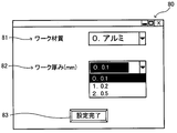
- the CPU 71 displays a work information input window 80 on the liquid crystal display 77, and inputs work information indicating the physical properties of the work W based on an operation by the input operation unit 76. Accept.
- the CPU 71 sets a reference distance used for determining the processing order based on the workpiece information received through the workpiece information input window 80 and a later-described reference distance setting table (see FIG. 11).
- the CPU 71 ends the reference distance setting process (S4) and shifts the process to S5 of the machining data processing program.
- the workpiece information input window 80 is displayed on the liquid crystal display 77 in the reference distance setting process (S4), and the workpiece information indicating the physical properties of the workpiece W in the current cutting process is performed by performing an operation using the input operation unit 76. Used for input.
- the workpiece information input window 80 includes a workpiece thickness setting unit 82, a workpiece material setting unit 81, and a setting completion button 83.
- the workpiece material setting unit 81 receives an input of the material (constituent material) of the workpiece W as one piece of workpiece information in the current cutting process.
- the workpiece material setting unit 81 is configured to be able to select the material of the workpiece W used for the current cutting process from a plurality of different workpiece W materials (for example, aluminum, iron, etc.) by an operation using the input operation unit 76. ing. This is because when the material of the workpiece W is different, the light absorptivity, thermal conductivity, and the like are different for each material, which affects the processing quality of the workpiece W by the pulse laser L. Therefore, the user can specify the material of the workpiece W used for the current cutting process by performing an operation on the workpiece material setting unit 81, and set the material of the workpiece W as one piece of workpiece information.
- the workpiece thickness setting unit 82 accepts input of the thickness (plate thickness) of the workpiece W as one piece of workpiece information in the current cutting process.
- the workpiece thickness setting unit 82 is configured to be able to select the thickness of the workpiece W used for the current cutting process from the thicknesses of a plurality of different workpieces W by an operation using the input operation unit 76. Therefore, the user can specify the thickness of the workpiece W used for the current cutting process by performing an operation on the workpiece thickness setting unit 82, and set the thickness of the workpiece W as one piece of workpiece information.
- the setting completion button 83 is used for an operation when input to each setting unit in the work information input window 80 is completed.
- the CPU 71 sets the conditions received by each setting unit of the work information input window 80 as work information in the current cutting process.
- the reference distance setting table is for determining the processing order of each processing point D in the processing data DW with respect to the material (constituent material) of the workpiece W and the thickness (plate thickness) of the workpiece W.
- a reference distance is associated with each other.
- the reference distance setting table since the light absorptivity, thermal conductivity, and the like are different for each material of the workpiece W, there are different reference distances for each material of the workpiece W (for example, aluminum, iron, etc.). It is associated. Further, in the reference distance setting table, the smaller the thickness of the workpiece W, the smaller the maximum heat input that the workpiece W can tolerate in the cutting process. Therefore, the smaller the thickness of the workpiece W, the larger the reference distance is associated. Yes.
- the CPU 71 performs the cutting process D on the basis of the work information input in the work information input window 80 and the reference distance setting table (see FIG. 11). It is possible to set a reference distance that can appropriately suppress the influence of machining in between. After the reference distance corresponding to the work information is stored in the RAM 72, the CPU 71 shifts the process to S5.
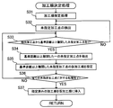
- the CPU 71 determines the machining order of all the machining points D included in the machining data DW at the time when the process proceeds to S5 by executing a machining order determination process.
- the CPU 71 reads a processing order determination process program (see FIG. 12) from the HDD 75 and executes it.
- the CPU 71 selects an arbitrary processing point D from all the processing points D included in the processing data DW at the time of shifting to S5 based on the operation of the input operation unit 76 in the PC 7. And accepts the input of the processing order desired by the user for the selected processing point D. After the selected machining point D and the machining order input to the machining point D are stored in the RAM 72, the CPU 71 shifts the process to S32.
- the machining point D for which the user-desired machining order is designated in the machining order designation process (S31) is referred to as “designated machining point”, and the user-desired machining point in the machining order designation process (S31).
- the machining point D for which the order is not designated is referred to as “undesignated machining point”.
- the CPU 71 randomly extracts one undesignated machining point from the undesignated machining points included in the machining data DW as a processing target.
- An undesignated processing point extracted as a processing target is referred to as an “extracted processing point”. After extracting one unspecified processing point and using it as the extracted processing point, the CPU 71 shifts the processing to S33.
- the CPU 71 determines the reference processing distance from the extracted processing point based on the XY coordinate data relating to the extracted processing point and other unspecified processing points and the reference distance set by the reference distance setting process (S4). It is determined whether there are unspecified machining points that are separated. When there is an undesignated machining point that is separated from the extracted machining point by a reference distance or more (S33: YES), the CPU 71 shifts the process to S34. On the other hand, when there is no undesignated machining point that is separated from the extracted machining point by the reference distance or more (S33: NO), the CPU 71 returns the process to S32 and extracts other undesignated machining points.
- the CPU 71 randomly extracts one undesignated machining point from undesignated machining points that are separated from the extracted machining point by a reference distance or more. After extracting one unspecified machining point, the CPU 71 shifts the process to S35.
- the CPU 71 sets a temporary processing order for one undesignated processing point that is separated from the extracted processing point by a reference distance or more and extracted in S34.
- the temporary processing order is set by assigning numbers in ascending order every time the process of S35 is executed.
- the CPU 71 shifts the processing to S36.
- the CPU 71 sets the undesignated machining point extracted in S34 as the next extracted machining point.
- the CPU 71 After shifting to S36, the CPU 71 has completed the processing for all undesignated machining points included in the machining data DW based on the processing result of the machining order designation process (S31) stored in the RAM 72 and the temporary machining order. Judge whether or not. When the process for all unspecified machining points included in the machining data DW has been completed (S36: YES), the CPU 71 shifts the process to S37. On the other hand, when the process for all unspecified machining points included in the machining data DW has not been completed (S36: NO), the CPU 71 returns the process to S33.
- the CPU 71 inserts the machining order related to each designated machining point designated in the machining order designation process (S31) with respect to the temporary machining order set based on the processes in S32 to S36, and the machining data DW
- the processing order related to all the processing points D included in is determined. By determining the machining order in this way, it is possible to reflect the user's wishes in the machining order while suppressing damage to the workpiece W accompanying the execution of the cutting process.
- the CPU 71 ends the processing order determination processing program, and shifts the processing to S6 of the processing data processing program.
- the CPU 71 executes the cooling period setting process so that the machining point D in the machining data DW is cut according to the machining order determined in the machining order determination process (S6).
- a cooling period for waiting for irradiation of the pulse laser L and scanning by the galvano scanner 19 is appropriately set according to the distance between the processing points D.
- the CPU 71 reads out and executes a cooling period setting process program (see FIG. 13) from the HDD 75.
- the CPU 71 specifies processing points D corresponding to two consecutive processing orders in order from the earliest processing order based on the information related to the processing order read in S41, and XY related to the two specified processing points D. Read coordinate data. After extracting the two processing points D having the continuous processing order, the CPU 71 shifts the processing to S43.
- the CPU 71 calculates the distance between the two machining points D extracted from the XY coordinate data of the two machining points D extracted in S42, and the distance between the two machining points D is equal to or greater than a predetermined value. It is determined whether or not.
- the CPU 71 shifts the process to S44.
- the CPU 71 shifts the process to S45.
- the CPU 71 sets the length of the cooling period in the process of scanning between the two extracted processing points D (that is, two processing points D in the sequential processing order) to the distance between the processing points D. Set the length accordingly. Specifically, the CPU 71 performs extraction by multiplying a ratio of a predetermined value to a distance between the two extracted processing points D (that is, a predetermined value / a distance between the two processing points D) in the reference cooling period. The cooling period corresponding to the distance between the two processed points D is calculated and set, and stored in the RAM 72.
- the reference cooling period means an initial value of the cooling period that is set when the distance between the two processing points D is smaller than a predetermined value.
- the CPU 71 refers to the cooling period stored in the RAM 72 and determines whether or not the processes (S42 to S44) regarding all the machining points D included in the machining data DW have been completed.
- the CPU 71 ends the cooling period setting processing program and shifts the processing to S7 of the processing data processing program.
- the CPU 71 returns the processing to S42, and the processing between the two processing points D in the next processing order (S42). To S44).
- the CPU 71 executes the machining execution process, and sends the machining data DW created through S1 to S6 to the laser controller 5 together with the machining start instruction for instructing to start the cutting process on the workpiece W.
- the processing data DW is set in the processing order determined in the processing order determination process (S5) and the cooling period setting process (S6) in addition to the XY coordinate data and laser intensity data of each processing point D indicating the cutting content. It is configured to include information on the cooling period.
- the CPU 61 of the laser controller 5 controls the laser driver 51 and the galvano driver 57 according to the received machining data, A cutting process for W is performed.
- the desired cutting process according to the process content of the process data DW is implement
- the laser processing apparatus 1 includes the laser oscillation unit 12 and the galvano scanner 19, and the laser controller 5, the power supply unit 6, and the PC 7. Connected with. According to the laser processing apparatus 1, the surface of the workpiece W can be processed by scanning the pulse laser L from the laser oscillation unit 12 with the galvano scanner 19.
- the laser machining system 100 executes the machining point setting process (S3), thereby corresponding the pitch of each machining point D arranged in each machining element DC of the machining data DW to the machining element length LC of the machining element DC. Therefore, the cutting process based on each machining element DC of the machining data DW can be performed on the workpiece W (S14). Then, according to the laser processing system 100, as shown in FIG. 8, per unit distance of the portion adjusted from the reference pitch P to the adjustment pitch PA according to the processing element length LC in the processing element DC of the processing data DW. Is adjusted from the energy density E to the adjusted energy density EA so as to be the same as before the pitch change (S15).
- each processing element DC in the processing data DW is arranged by changing a part of pitches among the plurality of processing points D corresponding to the processing element length LC ( S14)
- the cutting process according to each machining element DC can be realized, and at the same time, the energy density adjustment process (S15) can be executed, and the degradation of the machining quality due to the change in the pitch of the machining point D can be suppressed.
- the process point D is arrange
- the pitch of the machining point D at the other end of the machining element DC is adjusted from the reference pitch P to the adjustment pitch PA (S14), so that the energy density per unit distance in the part is the same as before the pitch change.
- one end side area where the pitch is not changed in the vicinity of the reference point, and the other end side area where the pitch is changed are suppressed. Can be clarified and the influence on processing can be controlled.
- the ratio of the adjustment pitch PA to the reference pitch P (that is, the adjustment pitch PA /) is added to the energy density E per unit distance for the portion adjusted from the reference pitch P to the adjustment pitch PA.
- the energy density per unit distance with respect to the adjustment pitch PA can be adjusted to be the same as the energy density E before the pitch adjustment, and thus the pitch of the machining point D is adjusted.
- the energy density per unit distance in the machining element DC can be maintained.
- the laser processing system 100 adjusts the number of pulses of the pulse laser L emitted from the laser oscillation unit 12 when adjusting from the energy density E to the adjustment energy density EA.
- the energy density per unit distance can be made the same as the energy density before the pitch change according to the adjustment from the reference pitch P to the adjustment pitch PA.
- the energy density per unit distance in the processing element DC is adjusted before and after the adjustment of the pitch of the processing point D. Can be kept, sure.
- CPU71 is.
- S3 duplicate machining point exclusion process
- S3 duplicate machining point exclusion process
- the cutting process is performed by irradiating the plurality of machining points D with the pulse laser L, damage to the workpiece W due to the irradiation with the pulse laser L is performed. May become too large, and the processing quality may be degraded.
- the pulse laser L is irradiated only to one processing point D among the plurality of processing points D located within the overlapping range, and the other processing points D are applied to the pulse laser. Since it is excluded from the irradiation target of L, excessive damage to the workpiece W due to the pulse laser L can be suppressed, and degradation of processing quality can be suppressed.
- the processing data DW is set so that the processing point D in the processing data DW is greater than or equal to the reference distance by executing the processing order determination process (S5).
- the processing order concerning all the processing points D in can be determined.
- the workpiece W is irradiated with the pulse laser L and the machining point D is cut, heat remains around the machining point D, and when the vicinity of the machining point D is continuously machined, The damage to W may become enormous.
- the processing order of each processing point D in the processing data is determined so that the distance between the two processing points D is equal to or greater than the reference distance, damage to the workpiece W is minimized.
- the cutting process based on the processing data DW can be executed while keeping the limit.
- the reference distance corresponding to the material of the workpiece W and the thickness of the workpiece W is set by executing the reference distance setting processing (S4) prior to the processing order determination processing (S5). (See FIGS. 10 and 11). Since the reference distance is used as a reference for determining the processing order in the processing order determination process (S5) (S33), according to the laser processing system 100, according to the physical properties of the workpiece W (depending on the constituent material and plate thickness, Since the processing order of each processing point D can be determined, cutting processing based on the processing data DW can be executed while minimizing damage to the workpiece W in an appropriate manner according to the configuration of the workpiece W. .
- an arbitrary processing point D is selected from the processing points D in the processing data DW by executing the processing order designation processing (S31) in the processing order determination processing (S5).
- the processing order for the selected processing point D can be set in the processing order desired by the user, and the cutting processing desired by the user can be realized.
- the laser processing system is used to determine the processing order related to the processing point D so that the distance between the two processing points D is greater than or equal to the reference distance. 100 can minimize damage to the workpiece W.
- the cooling period setting process (S6) is executed to cool the workpiece W when moving between two processing points D in a continuous processing order.
- the cooling period can be set according to the distance between the two processing points D. That is, when the influence of heat caused by the irradiation of the pulse laser L on the previous processing point D can affect the processing on the next processing point D at two consecutive processing points D, the laser processing system 100. Since the work W can be cooled by providing an appropriate cooling period, it is possible to suppress damage to the work W and to suppress deterioration in processing quality.
- the laser processing system 100 and the laser processing apparatus 1 are examples of the beam processing apparatus in the present invention.
- the laser oscillation unit 12 is an example of a beam emitting unit in the present invention
- the galvano scanner 19 is an example of an irradiation position moving unit in the present invention.
- the PC 7 and the control unit 70 are a processing data acquisition unit, an extraction condition determination unit, a processing point arrangement unit, a processing point change unit, an extraction condition adjustment unit, a determination unit, a processing point exclusion unit, a processing order determination unit, It is an example of a reference distance setting part, a determination part, and a cooling period setting part.
- the control unit 70, the input operation unit 76, and the work information input window 80 are examples of the processing condition acquisition unit in the present invention, and the control unit 70, the input operation unit 76, and the liquid crystal display 77 are examples of the processing order setting unit. It is.
- the pulse laser L is an example of a beam in the present invention, and the reference pitch P is an example of a predetermined pitch in the present invention.
- the processing data DW is an example of processing data in the present invention, and the processing point D is an example of processing points in the present invention.
- the present invention has been described above based on the embodiments. However, the present invention is not limited to the above-described embodiments, and various improvements and modifications can be made without departing from the spirit of the present invention.
- the laser processing apparatus 1 and the laser processing system 100 that emit the pulse laser L to perform cutting processing, trimming processing, or drilling processing are used. It is not limited to an aspect, It can be used for marking process etc. As long as processing on the workpiece W is possible, not only the pulse laser L but also various beams can be used.
- the adjustment is performed by changing the number of pulses of the pulse laser L.
- the present invention is limited to this mode. It is not something. For example, by increasing or decreasing the frequency of the pulse laser L, the energy density E applied to the workpiece W by the pulse laser L can be increased or decreased to be adjusted to the adjustment energy density EA. Similarly, by adjusting the peak power of the beam (for example, the pulse laser L), the energy density E applied to the workpiece W can be increased or decreased to be adjusted to the adjusted energy density EA.
- the energy density E is adjusted to the adjusted energy density EA by individually using the number of pulses in the pulse laser L, the frequency of the pulse laser L, and the peak power of the beam. It is also possible to adjust the adjustment energy density EA by increasing / decreasing the energy density E by adjusting a combination of a plurality of items in the number of pulses, beam peak power, and frequency of the pulse laser L.
- the processing order related to each processing point D of the processing data DW is determined using the reference distance set in the reference distance setting process (S4). It is not limited to this aspect.
- the machining order determination process (S5) after the unused machining point is extracted in S32, one unused machining point farthest from the extracted unused machining point in the machining data DW is extracted. It is also possible to extract so that the processing order is determined. Even in this case, it is possible to execute the cutting process based on the machining data DW while minimizing damage to the workpiece W.
- the CPU 71 sets a reference point at one end of the processing element DC in the processing data DW, and arranges the processing point D for each reference pitch P.
- the pitch between the processing points D and the energy density are adjusted for the other end of the processing element DC, but the present invention is not limited to this mode.
- the reference point related to the arrangement of the machining points D in the machining point arrangement process (S11) may not be the end of the machining element DC as long as it is on the machining element DC, and can be set to an appropriate position.
- adjustment of the pitch and energy density between the processing points D is performed at both ends of the processing element DC.
- the optical shutter unit 13 is configured to open and block the optical path of the pulse laser L by rotating the shutter 27 together with the motor shaft of the shutter motor 26.
- Various modes can be adopted as long as the configuration allows the optical path of the pulse laser L to be opened and closed by being moved.
- the shutter 27 may be rotated by a solenoid.
- the structure which slides the shutter 27 with a solenoid may be sufficient.
Landscapes
- Physics & Mathematics (AREA)
- Engineering & Computer Science (AREA)
- Optics & Photonics (AREA)
- Plasma & Fusion (AREA)
- Mechanical Engineering (AREA)
- Laser Beam Processing (AREA)
Abstract
単位距離当たりのエネルギー密度を保ちつつ、加工内容に基づく所望の加工を実行可能なビーム加工装置を提供する。レーザ加工システムにおいて、レーザ加工装置は、レーザ発振ユニットと、ガルバノスキャナとを有しており、レーザコントローラと、電源ユニットと、PCと接続されている。PCのCPUは、加工点設定処理(S3)を実行するで、加工データの各加工要素に配置された各加工点のピッチを、加工要素の加工要素長に対応して変更する。CPUは、加工データの加工要素における加工要素長に応じて、基準ピッチから調整ピッチに調整した部分についての単位距離当たりのエネルギー密度を、ピッチ変更前と同じになるように、エネルギー密度から調整エネルギー密度に調整する。
Description
本発明は、エネルギービームを照射してワークに加工を施すビーム加工装置に関する。
従来、エネルギービームを照射してワークを加工するビーム加工装置の一つとして、Qスイッチを有するYAGレーザから出射されるパルス状のレーザ光を用い、加工対象物であるワークを切断したり穴開けしたりするレーザ加工装置が知られている。
このようなビーム加工装置に関する発明として、特許文献1記載の発明が知られている。特許文献1記載のレーザ加工装置は、XYテーブル上にワークをセットし、各加工要素について、パルス状のレーザ光の照射方向と交差する方向にワークを移動させながら、ワークに各パルス状のレーザ光を連続的に照射していくように構成されている。
そして、特許文献1におけるレーザ光の照射は、各加工点間のピッチを一定に維持するように行われている。そして、特許文献1において、各加工点間のピッチを、加工要素の長さに応じて変更することによって、加工要素の長さと、各加工点間のピッチを対応させることができ、加工要素本来の長さで当該加工要素の加工を実現している。
しかしながら、当該特許文献1記載のレーザ加工装置は、加工要素の長さに応じて、各加工点間のピッチが調整される為、或る加工内容を構成する一の加工要素と、他の加工要素の長さが相違すると、一の加工要素における加工点間のピッチと、他の加工要素における加工点間のピッチとが相違することになる。
一の加工要素における加工点間のピッチと、他の加工要素における加工点間のピッチとが相違すると、一の加工要素に対する単位距離あたりのエネルギー密度と、他の加工要素に対する単位距離あたりのエネルギー密度とが相違することになる。即ち、特許文献1記載においては、或る加工内容を構成する加工要素ごとに、単位距離あたりのエネルギー密度が相違する場合があり、加工内容全体としての加工品質の低下を招いてしまう。
本開示は、上記の問題点に鑑みてなされたものであり、ビームを照射してワークに加工を施すビーム加工装置に関し、単位距離当たりのエネルギー密度を保ちつつ、加工内容に基づく所望の加工を実行可能なビーム加工装置を提供することを目的とする。
前記目的を達成するため、本発明の一側面に係るビーム加工装置は、前記ビーム出射部から出射されたビームの前記ワークにおける照射位置を相対移動させる照射位置移動部と、前記ビーム出射部からのビームを用いた加工内容を示す加工データを取得する加工データ取得部と、前記ビームを用いた前記ワークの加工に関する加工条件を取得する加工条件取得部と、前記加工条件取得部によって取得した加工条件に基づいて、前記ビーム出射部から出射されるビームの出射条件を決定する出射条件決定部と、前記加工データ取得部で取得した加工データに基づいて、前記加工データの加工内容を構成する線分に対して、前記ビームが照射される加工点を所定ピッチ毎に配置する加工点配置部と、前記加工データの加工内容に対応して、前記加工点配置部によって配置された前記加工点の一部のピッチを変更する加工点変更部と、前記加工点変更部によってピッチを変更した部分における前記ビームの加工点に対して、前記ビームの照射により与えられる単位距離あたりのエネルギー密度が、ピッチ変更前のエネルギー密度と同じになるように、前記出射条件決定部によって決定された出射条件を調整する出射条件調整部と、を有することを特徴とする。
当該ビーム加工装置は、ビーム出射部と、照射位置移動部と、加工データ取得部と、加工条件取得部と、出射条件決定部と、加工点配置部と、加工点変更部と、出射条件調整部と、を有しており、照射位置移動部により、前記ビーム出射部から出射されたビームの前記ワークにおける照射位置を相対移動させることで、前記加工データの加工内容に従って、ビームによるワークの加工を行い得る。そして、当該ビーム加工装置は、前記加工点配置部によって配置された前記加工点の一部のピッチを、加工点変更部によって前記加工データの加工内容に対応して、変更するので、加工データの加工内容に従って所望の加工をワークに施すことができる。そして、当該ビーム加工装置は、出射条件調整部によって、前記出射条件決定部によって決定された出射条件を調整することで、前記加工点変更部によってピッチを変更した部分における前記ビームの加工点に対して、前記ビームの照射により与えられる単位距離当たりのエネルギー密度が、ピッチ変更前と同じになるように変化させ、単位距離あたりのエネルギー密度を維持することができる。即ち、当該ビーム加工装置によれば、加工データの加工内容に従った所望の加工を実現すると同時に、加工点のピッチの変化に伴う加工品質の低下を抑制することができる。
本発明の他の側面に係るビーム加工装置は、請求項1記載のビーム加工装置であって、前記加工点配置部は、前記加工データの加工内容を構成する線分上に基準点を設定し、当該基準点を基準として、前記加工点を所定ピッチ毎に配置し、前記加工点変更部は、前記線分の一部における前記加工点のピッチを、前記加工データの加工内容に応じて変更することを特徴とする。
当該ビーム加工装置によれば、加工点配置部は、前記加工データの加工内容を構成する線分上に設定された基準点を基準として、前記加工点を所定ピッチ毎に配置し、前記加工点変更部は、前記線分の一部における前記加工点のピッチを、前記加工データの加工内容に応じて変更し、単位距離当たりのエネルギー密度が、ピッチ変更前と同じになるようにするため、加工点のピッチの変化に伴う加工品質の低下を抑制し、且つ基準点近傍におけるピッチが変更されない領域と、ピッチが変更される一部の領域を明確にし、加工への影響を制御することができる。
本発明の他の側面に係るビーム加工装置は、請求項1又は請求項2記載のビーム加工装置であって、前記加工点配置部は、前記加工データの加工内容を構成する線分の一端に基準点を設定し、当該基準点を基準として、前記加工点を所定ピッチ毎に配置し、前記加工点変更部は、前記線分の他端側における前記加工点のピッチを、前記加工データの加工内容に応じて変更することを特徴とする。
当該ビーム加工装置によれば、前記加工点配置部は、前記加工データの加工内容を構成する線分の一端に基準点を設定し、当該基準点を基準として、前記加工点を所定ピッチ毎に配置し、前記加工点変更部は、前記線分の他端側における前記加工点のピッチを、前記加工データの加工内容に応じて変更し、単位距離当たりのエネルギー密度が、ピッチ変更前と同じになるようにするため、加工点のピッチの変化に伴う加工品質の低下を抑制し、且つピッチが変更されない一端の領域と、ピッチが変更される他端の領域を明確にし、加工への影響を制御することができる。
本発明の他の側面に係るビーム加工装置は、請求項1乃至請求項3の何れかに記載のビーム加工装置であって、前記出射条件調整部は、前記加工点配置部による前記加工点のピッチと、前記加工点変更部によって変更された前記加工点のピッチとの比に比例して、前記ピッチを変更した部分に与えられる単位距離あたりのエネルギー密度がピッチ変更前と同じになるように、前記出射条件を調整することを特徴とする。
当該ビーム加工装置によれば、前記出射条件調整部は、前記加工点配置部による前記加工点のピッチと、前記加工点変更部によって変更された前記加工点のピッチとの比に比例して、前記ピッチを変更した部分に与えられる単位距離あたりのエネルギー密度がピッチ変更前と同じになるように、前記出射条件を調整する為、ピッチを変更した部分が存在する場合であっても、線分における単位距離あたりのエネルギー密度を保つことができる。
本発明の他の側面に係るビーム加工装置は、請求項1乃至請求項4の何れかに記載のビーム加工装置であって、前記出射条件調整部は、前記単位距離あたりのエネルギー密度がピッチ変更前と同じになるように、変更されたピッチに応じて、前記出射条件としての前記ビームのピークエネルギーを調整することを特徴とする。
当該ビーム加工装置によれば、前記出射条件調整部によって、前記出射条件として、前記ビームのピークエネルギーを調整することで、前記単位距離あたりのエネルギー密度を、変更されたピッチに応じてピッチ変更前の前記エネルギー密度と同じになるようにすることができ、線分における単位距離あたりのエネルギー密度を、確実に保つことができる。
本発明の他の側面に係るビーム加工装置は、請求項1乃至請求項5の何れかに記載のビーム加工装置であって、前記ビーム出射部は、前記ビームとして、パルスレーザを出射し、前記出射条件調整部は、前記単位距離あたりのエネルギー密度がピッチ変更前と同じになるように、変更されたピッチに応じて、前記出射条件としての前記パルスレーザのパルス数を調整することを特徴とする。
当該ビーム加工装置によれば、前記出射条件調整部によって、前記出射条件として、前記ビーム出射部から出射されるパルスレーザのパルス数を調整することで、前記単位距離あたりのエネルギー密度を、変更されたピッチに応じてピッチ変更前の前記エネルギー密度と同じになるようにすることができ、線分における単位距離あたりのエネルギー密度を、確実に保つことができる。
本発明の他の側面に係るビーム加工装置は、請求項1乃至請求項6の何れかに記載のビーム加工装置であって、前記ビーム出射部は、前記ビームとして、パルスレーザを出射し、前記出射条件調整部は、前記単位距離あたりのエネルギー密度がピッチ変更前と同じになるように、変更されたピッチに応じて、前記出射条件としての前記パルスレーザの周波数を調整することを特徴とする。
当該ビーム加工装置によれば、前記出射条件調整部によって、前記出射条件として、前記ビーム出射部から出射されるパルスレーザの周波数を調整することで、前記単位距離あたりのエネルギー密度を、変更されたピッチに応じてピッチ変更前の前記エネルギー密度と同じになるようにすることができ、線分における単位距離あたりのエネルギー密度を、確実に保つことができる。
本発明の他の側面に係るビーム加工装置は、請求項1乃至請求項7の何れかに記載のビーム加工装置であって、前記加工データの加工内容を構成する一の加工要素における加工点と、前記加工データの加工内容を構成する他の加工要素における加工点とが所定範囲内に位置するか否かを判断する判断部と、前記判断部によって、前記一の加工要素における加工点と、前記他の加工要素における加工点が所定範囲内であると判断された場合に、前記一の加工要素における加工点と、前記他の加工要素における加工点の何れか一方に対する前記ビームの出射を中止する加工点除外部と、を有することを特徴とする。
当該ビーム加工装置は、判断部と、加工点除外部とを有し、前記判断部によって、前記一の加工要素における加工点と、前記他の加工要素における加工点が所定範囲内であると判断された場合に、前記一の加工要素における加工点と、前記他の加工要素における加工点の何れか一方に対する前記ビームの出射を中止する。ここで、一の加工要素における加工点と他の加工要素における加工点が所定範囲内にある場合、両加工点にビームを照射して加工すると、ビームの照射によるワークへのダメージが大きくなりすぎ、加工品質を低下させてしまう場合がある。この点、当該ビーム加工装置によれば、前記一の加工要素における加工点と、前記他の加工要素における加工点の何れか一方に対する前記ビームの出射を中止する為、ビームによるワークへの過剰なダメージを抑制することができ、加工品質の低下を抑制することができる。
ことができる。
ことができる。
本発明の他の側面に係るビーム加工装置は、請求項1乃至請求項8の何れかに記載のビーム加工装置であって、前記加工データの加工内容に対して配置された各加工点に含まれる一の加工点と、当該一の加工点の次に加工される加工点との間の距離が、基準距離以上となるように、前記加工データの加工内容に対して配置された各加工点の加工順を決定する加工順決定部を有することを特徴とする。
当該ビーム加工装置は、加工順決定部を有しており、前記加工データの加工内容に対して配置された各加工点に含まれる一の加工点と、当該一の加工点の次に加工される加工点との間の距離が、基準距離以上となるように、前記加工データの加工内容に対して配置された各加工点の加工順を決定する。当該ビーム加工装置において、ワークにビームを照射して加工点を加工した場合、当該加工点の周囲には熱が残り、当該加工点近傍を連続して加工すると、ワークに対するダメージが多大なものとなってしまう場合がある。この点、当該ビーム加工装置によれば、一の加工点と、当該一の加工点の次に加工される加工点との間の距離が、基準距離以上となるように、前記加工データの加工内容に対して配置された各加工点の加工順を決定する為、ワークに対するダメージを最小限に留めつつ、加工データに基づく加工を実行し得る。
本発明の他の側面に係るビーム加工装置は、請求項9記載のビーム加工装置であって、前記加工条件取得部は、前記加工条件として、前記ワークの構成に関する情報を取得し、前記加工条件取得部によって取得された前記ワークの構成に関する情報に基づいて、前記基準距離を設定する基準距離設定部を有することを特徴とする。
当該ビーム加工装置は、基準距離設定部を有しており、前記加工条件取得部によって取得された前記ワークの構成に関する情報(例えば、厚みや材質等)に基づいて、前記基準距離を設定する。ここで、当該基準距離は、加工順決定部における加工順の決定に関する基準として用いられる為、当該ビーム加工装置によれば、ワークの構成に関する情報に応じて、各加工点の加工順を決定することができるので、当該ワークに対するダメージを、ワークの構成に応じた適切な態様で最小限に留めつつ、加工データに基づく加工を実行し得る。
本発明の他の側面に係るビーム加工装置は、請求項9又は請求項10記載のビーム加工装置であって、前記加工データの加工内容に対して配置された加工点から任意の加工点の選択を受け付けると共に、選択された加工点に対する加工順の設定を受け付ける加工順設定部を有し、前記加工順決定部は、前記加工データの加工内容に対して配置された各加工点の内、前記加工順設定部で加工順が設定された加工点及び加工順を除いて、前記加工データの加工内容における加工点の加工順を決定することを特徴とする。
当該ビーム加工装置は、前記加工データの加工内容に対して配置された加工点から任意の加工点の選択を受け付けると共に、選択された加工点に対する加工順の設定を受け付ける加工順設定部を有し、前記加工順決定部は、前記加工データの加工内容に対して配置された各加工点の内、前記加工順設定部で加工順が設定された加工点及び加工順を除いて、前記加工データの加工内容における加工点の加工順を決定する。即ち、当該ビーム加工装置によれば、加工順設定部により設定された加工点については、ユーザ所望の加工順とすることができるので、ユーザ所望の加工を実現し得る。又、加工順設定部によって設定された加工点以外については、加工順決定部によって、加工順が決定されるので、当該ビーム加工装置は、ワークに対するダメージを最小限に留めることができる。
本発明の他の側面に係るビーム加工装置は、請求項9乃至請求項11の何れかに記載のビーム加工装置であって、前記加工順決定部によって決定された加工順において、連続する2つの加工点間の距離が所定距離未満であるか否かを判定する判定部と、前記判定部によって、前記連続する2つの加工点間の距離が所定距離未満であると判定された場合に、前記ビームの照射位置が前記連続する2つの加工点間を移動する際に、前記ワークを冷却する為の冷却期間を設定する冷却期間設定部と、を有することを特徴とする。
当該ビーム加工装置は、判定部と、冷却期間設定部とを有し、前記判定部によって、前記加工順において連続する2つの加工点間の距離が所定距離未満であると判定された場合に、前記ビームの照射位置が前記連続する2つの加工点間を移動する際に、前記ワークを冷却する為の冷却期間を設定する。即ち、連続する2つの加工点において、先の加工点に対するビームの照射に起因する熱の影響が、次の加工点に対する加工に影響を及ぼし得る場合に、当該ビーム加工装置は、冷却期間を設けて、ワークを冷却することができるので、ワークに対するダメージを抑え、加工品質の低下を抑制することができる。
以下、本発明に関するビーム加工装置を、ビームとしてのパルスレーザLを用いて切断加工を行い得るレーザ加工装置1を含むレーザ加工システム100として具体化した実施形態について、図面を参照しつつ詳細に説明する。尚、ここでの切断加工は、加工対象物を単に分割するだけの加工ではなく、トリミング加工や穿孔加工等、加工対象物の一部除去による幅広い加工を含む。
(レーザ加工システム100の概略構成)
先ず、本実施形態に関するレーザ加工システム100の概略構成について、図1を参照しつつ詳細に説明する。レーザ加工システム100は、レーザ加工装置1と、PC7を有しており、PC7によって作成された加工データDWに従って、レーザ加工装置1を制御することで、加工対象物(例えば、ワークW)の表面上に対して、ビームとしてのパルスレーザLを2次元走査して切断加工を行うように構成されている。
先ず、本実施形態に関するレーザ加工システム100の概略構成について、図1を参照しつつ詳細に説明する。レーザ加工システム100は、レーザ加工装置1と、PC7を有しており、PC7によって作成された加工データDWに従って、レーザ加工装置1を制御することで、加工対象物(例えば、ワークW)の表面上に対して、ビームとしてのパルスレーザLを2次元走査して切断加工を行うように構成されている。
(レーザ加工装置の概略構成)
次に、レーザ加工システム100を構成するレーザ加工装置1の概略構成について、図面を参照しつつ詳細に説明する。図1に示すように、本実施形態に関するレーザ加工装置1は、レーザ加工装置本体部2と、レーザコントローラ5と、電源ユニット6により構成されている。
次に、レーザ加工システム100を構成するレーザ加工装置1の概略構成について、図面を参照しつつ詳細に説明する。図1に示すように、本実施形態に関するレーザ加工装置1は、レーザ加工装置本体部2と、レーザコントローラ5と、電源ユニット6により構成されている。
レーザ加工装置本体部2は、加工対象物(例えば、ワークW)に対して、パルスレーザLを照射し、当該パルスレーザLを2次元走査して、加工対象物の切断加工を行う。レーザコントローラ5は、コンピュータで構成され、PC7と双方向通信可能に接続されると共に、レーザ加工装置本体部2及び電源ユニット6と電気的に接続されている。PC7は、パーソナルコンピュータによって構成されており、加工対象物の切断加工を行う際の加工データDWの作成、加工条件に応じた制御パラメータの設定を行う際等に用いられる。そして、レーザコントローラ5は、PC7から送信された加工データDW、制御パラメータ、各種指示情報等に基づいてレーザ加工装置本体部2及び電源ユニット6を駆動制御する。尚、ワークWは、加工対象物であるワークWの一例に該当する。
尚、図1は、レーザ加工システム100及びレーザ加工装置1の概略構成を示すものであるため、レーザ加工装置本体部2を模式的に示している。従って、当該レーザ加工装置本体部2の具体的な構成については、後述する。
(レーザ加工装置本体部2の概略構成)
次に、レーザ加工装置本体部2の概略構成について、図1、図2に基づいて説明する。尚、レーザ加工装置本体部2の説明において、図1の左方向、右方向、上方向、下方向が、それぞれレーザ加工装置本体部2の前方向、後方向、上方向、下方向である。従って、レーザ発振器21のパルスレーザLの出射方向が前方向である。本体ベース11及びパルスレーザLに対して垂直な方向が上下方向である。そして、レーザ加工装置本体部2の上下方向及び前後方向に直交する方向が、レーザ加工装置本体部2の左右方向である。
次に、レーザ加工装置本体部2の概略構成について、図1、図2に基づいて説明する。尚、レーザ加工装置本体部2の説明において、図1の左方向、右方向、上方向、下方向が、それぞれレーザ加工装置本体部2の前方向、後方向、上方向、下方向である。従って、レーザ発振器21のパルスレーザLの出射方向が前方向である。本体ベース11及びパルスレーザLに対して垂直な方向が上下方向である。そして、レーザ加工装置本体部2の上下方向及び前後方向に直交する方向が、レーザ加工装置本体部2の左右方向である。
レーザ加工装置本体部2は、パルスレーザLと可視レーザ光Mをfθレンズ20から同軸上に出射するレーザヘッド部3(図2参照)と、レーザヘッド部3が上面に固定される略箱体状の加工容器(図示せず)とから構成されている。
図2に示すように、レーザヘッド部3は、本体ベース11と、パルスレーザLを出射するレーザ発振ユニット12と、光シャッター部13と、光ダンパー14と、ハーフミラー15と、ガイド光部16と、反射ミラー17と、光センサ18と、ガルバノスキャナ19と、fθレンズ20等から構成され、略直方体形状の筐体カバー(図示せず)で覆われている。
レーザ発振ユニット12は、レーザ発振器21と、ビームエキスパンダ22と、取付台23とから構成されている。レーザ発振器21は、ファイバコネクタと、集光レンズと、反射鏡と、レーザ媒質と、受動Qスイッチと、出力カプラーと、ウィンドウとをケーシング内に有している。ファイバコネクタには、光ファイバFが接続されており、電源ユニット6を構成する励起用半導体レーザ部40から出射された励起光が、光ファイバFを介して入射される。
集光レンズは、ファイバコネクタから入射された励起光を集光する。反射鏡は、集光レンズによって集光された励起光を透過すると共に、レーザ媒質から出射されたレーザ光を高効率で反射する。レーザ媒質は、励起用半導体レーザ部40から出射された励起光によって励起されてレーザ光を発振する。レーザ媒質としては、例えば、レーザ活性イオンとしてネオジウム(Nd)が添加されたネオジウム添加ガドリニウムバナデイト(Nd:GdVO4)結晶や、ネオジウム添加イットリウムバナデイト(Nd:YVO4)結晶や、ネオジウム添加イットリウムアルミニウムガーネット(Nd:YAG)結晶等を用いることができる。
受動Qスイッチは、内部に蓄えられた光エネルギーが或る一定値を超えたとき、透過率が高くなるという性質を持った結晶である。従って、受動Qスイッチは、レーザ媒質によって発振されたレーザ光をパルス状のパルスレーザLとして発振するQスイッチとして機能する。受動Qスイッチとしては、例えば、クローム添加YAG(Cr:YAG)結晶やCr:MgSiO4結晶等を用いることができる。
出力カプラーは、反射鏡とレーザ共振器を構成する。出力カプラーは、例えば、表面に誘電体多層膜をコーティングした凹面鏡により構成された部分反射鏡で、波長1064nmでの反射率は、80%~95%である。ウィンドウは、合成石英等から形成され、出力カプラーから出射されたレーザ光を外部へ透過させる。従って、レーザ発振器21は、受動Qスイッチを介してパルスレーザを発振し、ワークWの切断加工を行うためのレーザ光として、パルスレーザLを出力する。
ビームエキスパンダ22は、パルスレーザLのビーム径を変更するものであり、レーザ発振器21と同軸に設けられている。取付台23は、レーザ発振器21がパルスレーザLの光軸を調整可能に取り付けられ、本体ベース11の前後方向中央位置よりも後側の上面に対して、各取付ネジ25によって固定されている。
光シャッター部13は、シャッターモータ26と、平板状のシャッター27とから構成されている。シャッターモータ26は、ステッピングモータ等で構成されている。シャッター27は、シャッターモータ26のモータ軸に取り付けられて同軸に回転する。シャッター27は、ビームエキスパンダ22から出射されたパルスレーザLの光路を遮る位置に回転した際には、パルスレーザLを光シャッター部13に対して右方向に設けられた光ダンパー14へ反射する。一方、シャッター27がビームエキスパンダ22から出射されたパルスレーザLの光路上に位置しないように回転した場合には、ビームエキスパンダ22から出射されたパルスレーザLは、光シャッター部13の前側に配置されたハーフミラー15に入射する。
光ダンパー14は、シャッター27で反射されたパルスレーザLを吸収する。尚、光ダンパー14の発熱は、本体ベース11に熱伝導されて冷却される。ハーフミラー15は、パルスレーザLの光路に対して斜め左下方向に45度の角度を形成するように配置される。ハーフミラー15は、後側から入射されたパルスレーザLのほぼ全部を透過する。又、ハーフミラー15は、後側から入射されたパルスレーザLの一部を、45度の反射角で反射ミラー17へ反射する。反射ミラー17は、ハーフミラー15のパルスレーザLが入射される後側面の略中央位置に対して左方向に配置される。
ガイド光部16は、可視レーザ光として、例えば、赤色レーザ光を出射する可視半導体レーザ28と、可視半導体レーザ28から出射された可視レーザ光Mを平行光に収束するレンズ群(図示せず)とから構成されている。可視レーザ光Mは、レーザ発振器21から出射されるパルスレーザLと異なる波長である。ガイド光部16は、ハーフミラー15のパルスレーザLが出射される略中央位置に対して右方向に配置されている。この結果、可視レーザ光Mは、ハーフミラー15のパルスレーザLが出射される略中央位置において、ハーフミラー15の前側面にあたる反射面に対して45度の入射角で入射され、45度の反射角でパルスレーザLの光路上に反射される。即ち、可視半導体レーザ28は、可視レーザ光MをパルスレーザLの光路上に出射する。
反射ミラー17は、パルスレーザLの光路に対して平行な前後方向に対して斜め左下方向に45度の角度を形成するように配置され、ハーフミラー15の後側面において反射されたパルスレーザLの一部が、反射面の略中央位置に対して45度の入射角で入射される。そして、反射ミラー17は、反射面に対して45度の入射角で入射されたパルスレーザLを、45度の反射角で前側方向へ反射する。
光センサ18は、パルスレーザLの発光強度を検出するフォトダイオード等で構成され、反射ミラー17のパルスレーザLが反射される略中央位置に対して、図2中、前側方向に配置されている。この結果、光センサ18は、反射ミラー17で反射されたパルスレーザLが入射され、この入射されたパルスレーザLの出力強度を検出する。従って、光センサ18を介してレーザ発振器21から出力されるパルスレーザLの強度を検出することができる。
ガルバノスキャナ19は、本体ベース11の前側端部に形成された貫通孔29の上側に取り付けられ、レーザ発振ユニット12から出射されたパルスレーザLと、ハーフミラー15で反射された可視レーザ光Mとを下方へ2次元走査する。ガルバノスキャナ19は、ガルバノX軸モータ31と、ガルバノY軸モータ32と、本体部33により構成されており、ガルバノX軸モータ31とガルバノY軸モータ32は、それぞれのモータ軸が互いに直交するように外側からそれぞれの取付孔に嵌入、保持されて本体部33に取り付けられている。従って、当該ガルバノスキャナ19においては、各モータ軸の先端部に取り付けられた走査ミラーが内側で互いに対向している。そして、ガルバノX軸モータ31、ガルバノY軸モータ32の回転をそれぞれ制御して、各走査ミラーを回転させることによって、パルスレーザLと可視レーザ光Mとを下方へ2次元走査する。この2次元走査方向は、前後方向(X方向)と左右方向(Y方向)である。
fθレンズ20は、下方に配置された加工対象物(ワークW等)の表面に対して、ガルバノスキャナ19によって2次元走査されたパルスレーザLと可視レーザ光Mとを同軸に集光する。そして、当該fθレンズ20は、パルスレーザLや可視レーザ光M等を収束した焦点を、平面状の焦点面とすると共に、パルスレーザLや可視レーザ光Mの走査速度が一定になるように補正する。従って、ガルバノX軸モータ31、ガルバノY軸モータ32の回転を制御することによって、パルスレーザLと可視レーザ光Mが、ワークW表面上において、所望の加工パターンで前後方向(X方向)と左右方向(Y方向)に2次元走査される。
(電源ユニットの概略構成)
次に、レーザ加工装置1における電源ユニット6の概略構成について、図1を参照しつつ説明する。図1に示すように、電源ユニット6は、励起用半導体レーザ部40と、レーザドライバ51と、電源部52と、冷却ユニット53とを、ケーシング55内に有している。電源部52は、励起用半導体レーザ部40を駆動する駆動電流を、レーザドライバ51を介して励起用半導体レーザ部40に供給する。レーザドライバ51は、レーザコントローラ5から入力される駆動情報に基づいて、励起用半導体レーザ部40を直流でオンオフ駆動する。
次に、レーザ加工装置1における電源ユニット6の概略構成について、図1を参照しつつ説明する。図1に示すように、電源ユニット6は、励起用半導体レーザ部40と、レーザドライバ51と、電源部52と、冷却ユニット53とを、ケーシング55内に有している。電源部52は、励起用半導体レーザ部40を駆動する駆動電流を、レーザドライバ51を介して励起用半導体レーザ部40に供給する。レーザドライバ51は、レーザコントローラ5から入力される駆動情報に基づいて、励起用半導体レーザ部40を直流でオンオフ駆動する。
励起用半導体レーザ部40は、光ファイバFによってレーザ発振器21に光学的に接続されている。励起用半導体レーザ部40は、レーザドライバ51から入力されるパルス状の駆動電流に対して、レーザ光を発生する閾値電流を超えた電流値に比例した出力の波長のレーザ光である励起光を、光ファイバF内に出射する。従って、レーザ発振器21には、励起用半導体レーザ部40からの励起光が光ファイバFを介して入射される。励起用半導体レーザ部40には、例えば、GaAsを用いたバー型半導体レーザを用いることができる。
冷却ユニット53は、電源部52及び励起用半導体レーザ部40を、所定の温度範囲内に調整する為のユニットであり、例えば、電子冷却方式により冷却することで、励起用半導体レーザ部40の温度制御を行っており、励起用半導体レーザ部40の発振波長を微調整する。尚、冷却ユニット53は、水冷式の冷却ユニットや、空冷式の冷却ユニット等を用いるようにしてもよい。
(レーザ加工システム100の制御系)
次に、レーザ加工システム100を構成するレーザ加工装置1の制御系構成について、図面を参照しつつ説明する。図3に示すように、レーザ加工装置1は、レーザ加工装置1の全体を制御するレーザコントローラ5と、レーザドライバ51と、ガルバノコントローラ56と、ガルバノドライバ57と、可視光レーザドライバ58等を有して構成されている。レーザコントローラ5には、レーザドライバ51と、ガルバノコントローラ56と、光センサ18と、可視光レーザドライバ58等が電気的に接続されている。
次に、レーザ加工システム100を構成するレーザ加工装置1の制御系構成について、図面を参照しつつ説明する。図3に示すように、レーザ加工装置1は、レーザ加工装置1の全体を制御するレーザコントローラ5と、レーザドライバ51と、ガルバノコントローラ56と、ガルバノドライバ57と、可視光レーザドライバ58等を有して構成されている。レーザコントローラ5には、レーザドライバ51と、ガルバノコントローラ56と、光センサ18と、可視光レーザドライバ58等が電気的に接続されている。
レーザコントローラ5は、レーザ加工装置1の全体の制御を行う演算装置及び制御装置としてのCPU61、RAM62、ROM63、時間を計測するタイマ64等を備えている。又、CPU61、RAM62、ROM63、タイマ64は、バス線(図示せず)により相互に接続されて、相互にデータのやり取りが行われる。
RAM62は、CPU61により演算された各種の演算結果や加工データDWにおける各加工点DのXY座標データ等を一時的に記憶させておくためのものである。ROM63は、各種のプログラムを記憶させておくものであり、PC7から送信された加工データDWに基づいて、加工要素DCを構成する各加工点DのXY座標データを算出してRAM62に記憶する等の各種プログラムが記憶されている。ROM63には、フォントの種類別に、直線と楕円弧とで構成された各文字のフォントの始点、終点、焦点、曲率等のデータが記憶されている。
そして、CPU61は、ROM63に記憶されている各種の制御プログラムに基づいて各種の演算及び制御を行なうものである。例えば、CPU61は、PC7から入力された加工データDWに基づいて、加工要素DCにおける各加工点DのXY座標データ、ガルバノ走査速度情報等をガルバノコントローラ56に出力する。又、CPU61は、PC7から入力された励起用半導体レーザ部40に対する駆動電流の供給制御や、励起用半導体レーザ部40からの励起光出力、励起光の出力期間等の情報を、レーザドライバ51に出力する。又、CPU61は、各加工点DのXY座標データ、ガルバノスキャナ19のON・OFFを指示する制御信号等をガルバノコントローラ56に出力する。
レーザドライバ51は、レーザコントローラ5から入力された励起用半導体レーザ部40に関する制御パラメータ(例えば、駆動電流の電流値、励起光出力、励起光の出力期間等)に基づいて、励起用半導体レーザ部40を駆動制御する。具体的には、レーザドライバ51は、レーザコントローラ5から入力された駆動電流の電流値に関する制御パラメータに基づいて、パルス状の駆動電流を発生し、励起用半導体レーザ部40に供給する。これにより、励起用半導体レーザ部40は、駆動電流の電流値に対応する強度の励起光を、所定の供給期間の間、光ファイバF内に供給する。
ガルバノコントローラ56は、レーザコントローラ5から入力された各加工点DのXY座標データ、ガルバノ走査速度情報等に基づいて、ガルバノX軸モータ31とガルバノY軸モータ32の駆動角度、回転速度等を算出して、駆動角度、回転速度を表すモータ駆動情報をガルバノドライバ57へ出力する。
ガルバノドライバ57は、ガルバノコントローラ56から入力された駆動角度、回転速度を表すモータ駆動情報に基づいて、ガルバノX軸モータ31とガルバノY軸モータ32を駆動制御して、パルスレーザLを2次元走査する。
可視光レーザドライバ58は、レーザコントローラ5から出力される制御信号に基づいて、可視半導体レーザ28を含むガイド光部16の制御を行い、例えば、制御信号に基づいて、可視半導体レーザ28から出射される可視レーザ光Mの発光タイミングや光量を制御する。
図1、図3に示すように、レーザコントローラ5には、PC7が双方向通信可能に接続されており、PC7から送信された加工内容を示す加工データDW、レーザ加工装置本体部2の制御パラメータ、ユーザからの各種指示情報等を受信可能に構成されている。
(PCの制御系)
続いて、レーザ加工システム100を構成するPC7の制御系構成について、図面を参照しつつ説明する。図3に示すように、PC7は、PC7の全体を制御する制御部70と、マウスやキーボード等から構成される入力操作部76と、液晶ディスプレイ77と、CD-ROM79に対する各種データ、プログラム等の書き込み及び読み込みを行うためのCD-R/W78等から構成されている。
続いて、レーザ加工システム100を構成するPC7の制御系構成について、図面を参照しつつ説明する。図3に示すように、PC7は、PC7の全体を制御する制御部70と、マウスやキーボード等から構成される入力操作部76と、液晶ディスプレイ77と、CD-ROM79に対する各種データ、プログラム等の書き込み及び読み込みを行うためのCD-R/W78等から構成されている。
制御部70は、PC7の全体の制御を行うと共に、レーザコントローラ5を介して、レーザ加工システム100全体の制御を行う演算装置及び制御装置としてのCPU71と、RAM72と、ROM73と、時間を計測するタイマ74と、HDD75等を備えている。又、CPU71と、RAM72と、ROM73と、タイマ74は、バス線(図示せず)により相互に接続されて、相互にデータのやり取りが行われる。又、CPU71とHDD75は、入出力インターフェース(図示せず)を介して接続され、相互にデータのやり取りが行われる。
RAM72は、CPU71により演算された各種の演算結果等を一時的に記憶させておくためのものである。ROM73は、各種の制御プログラムやデータテーブルを記憶させておくものである。
そして、HDD75は、各種アプリケーションソフトウェアのプログラム、各種データファイルを記憶する記憶装置であり、本実施形態においては、加工データDWを作成する為の加工データ処理プログラム(図4参照)や各種サブルーチン(図6、図9、図12参照)や、後述する基準距離を設定する際に参照される基準距離設定テーブル(図11参照)等の各種データテーブルを記憶している。
そして、CD-R/W78は、アプリケーションプログラム、各種データテーブル等のデータ群を、CD-ROM79から読み込む、又は、CD-ROM79に対して書き込む。即ち、PC7は、CD-R/W78を介して、加工データ処理プログラム及びサブルーチン(図4等参照)や、基準距離設定テーブル(図11参照)をCD-ROM79から読み込み、HDD75に格納する。
尚、加工データ処理プログラム及びサブルーチン(図4等参照)や、基準距離設定テーブル(図11参照)は、ROM73に記憶されていても良いし、CD-ROM79等の記憶媒体から読み込まれても良い。又、インターネット等のネットワーク(図示せず)を介して、ダウンロードされてもよい。
そして、PC7には、入出力インターフェース(図示せず)を介して、マウスやキーボード等から構成される入力操作部76と、液晶ディスプレイ77等が電気的に接続されている。従って、PC7は、入力操作部76や、液晶ディスプレイ77を用いて、ワークWの物性に関するワーク情報(例えば、ワークWの材質や、ワークWの厚み等)の設定や、レーザ加工の実行開始指示等を行う際に利用される。
(加工データ処理プログラムの処理内容)
続いて、PC7において実行される加工データ処理プログラムの処理内容について、図面を参照しつつ詳細に説明する。当該加工データ処理プログラムは、加工データを作成する際に実行されるアプリケーションプログラムであり、CPU71によって実行される。
続いて、PC7において実行される加工データ処理プログラムの処理内容について、図面を参照しつつ詳細に説明する。当該加工データ処理プログラムは、加工データを作成する際に実行されるアプリケーションプログラムであり、CPU71によって実行される。
図4に示すように、加工データ処理プログラムの実行を開始すると、CPU71は、先ず、加工データ生成処理を実行して、切断加工により切断される内容を示す加工データDWを生成する(S1)。当該加工データDWをRAM72に格納した後、CPU71は、S2に処理を移行する。
(加工データDWの構成)
ここで、加工データ生成処理(S1)で生成される加工データDWについて、図5を参照しつつ詳細に説明する。図5に示すように、加工データDWは、ワークW表面に対してパルスレーザLによって切断される内容、及び、当該切断内容に従って切断加工する際の加工順等の制御パラメータを含んで構成されている。当該加工データDWにおける切断内容は、一又は複数の加工要素DCを組み合わせて表現される。一の加工要素DCは、図5に示すような、円形、直線、多角形等の一筆書きで切断可能な内容を示す。
本実施形態においては、ユーザは、PC7の入力操作部76等を操作することによって、所望の加工要素DCを適宜配置し、組み合わせることで、加工データDWにおける切断内容を設定することができる。
ここで、加工データ生成処理(S1)で生成される加工データDWについて、図5を参照しつつ詳細に説明する。図5に示すように、加工データDWは、ワークW表面に対してパルスレーザLによって切断される内容、及び、当該切断内容に従って切断加工する際の加工順等の制御パラメータを含んで構成されている。当該加工データDWにおける切断内容は、一又は複数の加工要素DCを組み合わせて表現される。一の加工要素DCは、図5に示すような、円形、直線、多角形等の一筆書きで切断可能な内容を示す。
本実施形態においては、ユーザは、PC7の入力操作部76等を操作することによって、所望の加工要素DCを適宜配置し、組み合わせることで、加工データDWにおける切断内容を設定することができる。
S2においては、CPU71は、加工点設定処理を実行することによって、加工データDWの切断内容を表現する為に、当該切断内容に従って複数の加工点Dを配置する。当該加工点設定処理(S2)では、CPU71は、HDD75から加工点設定処理プログラム(図6参照)を読み出して実行する。
(加工点設定処理プログラムの処理内容)
ここで、加工点設定処理(S2)で実行される加工点設定処理プログラムの処理内容について、図6を参照しつつ詳細に説明する。図6に示すように、加工点設定処理プログラムの実行を開始すると、CPU71は、加工点配置処理を実行する(S11)。
ここで、加工点設定処理(S2)で実行される加工点設定処理プログラムの処理内容について、図6を参照しつつ詳細に説明する。図6に示すように、加工点設定処理プログラムの実行を開始すると、CPU71は、加工点配置処理を実行する(S11)。
加工点配置処理(S11)では、CPU71は、加工データDWにおける各加工要素DCに対して、多数の加工点Dを所定の基準ピッチPで配置する。例えば、図5に示す加工データDWの場合、CPU71が加工点配置処理(S11)を実行することで、加工データDWにおける各加工要素DCに対して複数の加工点Dを配置する(図7参照)。
この加工点配置処理(S11)について具体的に説明すると、CPU71は、先ず、加工データDWにおける一の加工要素DCを処理対象として設定し、当該加工要素DCの線上に基準点を設定し、当該基準点を基準として所定の基準ピッチP毎に加工点Dを配置する。本実施形態においては、CPU71は、加工要素DCの一端部に基準点を設定し、当該基準点を基準として、基準ピッチP毎に加工点Dを配置する(図8(A)参照)。加工要素DCに対して、基準ピッチP毎に加工点Dを配置することによって、CPU71は、単位距離当たりのエネルギー密度Eを設定し得る。このようにして、加工データDWにおける各加工要素DCに対して、基準ピッチP毎に加工点Dを配置した後、CPU71は、S12に処理を移行する。
S12に移行すると、CPU71は、加工点配置処理(S11)により基準ピッチP毎に加工点Dが配置された加工データDWから、一の加工要素DCを処理対象として抽出する。一の加工要素DCを処理対象として抽出した後、CPU71は、S13に処理を移行する。
S13においては、CPU71は、処理対象として抽出された加工要素DCの加工要素長LCが基準ピッチPのN倍(N=1、2、3…N)であるか否かを判断する。即ち、S13における判断処理では、当該加工要素DCの加工要素長LCが基準ピッチPで割り切れるか否かを判断している。加工要素DCの加工要素長LCが基準ピッチPのN倍でない場合(S13:YES)、CPU71は、S14に処理を移行する。一方、加工要素DCの加工要素長LCが基準ピッチPのN倍である場合(S13:NO)、CPU71は、S16に処理を移行する。
S14では、CPU71は、処理対象として抽出された加工要素DCに対して、加工点調整処理を実行する。この場合の処理態様である加工要素DCは、加工要素長LCが基準ピッチPのN倍ではなく、ずれが生じている状態である。従って、当該加工点調整処理(S14)においては、CPU71は、当該加工要素DCの内、加工要素DCの端部と加工点Dの位置がずれている端部において、端部側における加工点Dの位置を、当該加工要素DCの端部と一致するように調整する。
ここで、加工点調整処理(S14)の処理内容について、具体例を挙げて説明する。具体例としては、図5、図7に示す加工データDWから、処理対象として、直線を為す加工要素DCを抽出した場合を用いる。ここで、図8(A)に示すように、加工点配置処理(S11)において、直線をなす加工要素DCに対しては、図8における左側に位置する一端部に基準点が設定され、基準ピッチP毎に加工点Dが配置される。この時、所定の基準ピッチPに対応して、単位距離当たりのエネルギー密度Eが設定される。
図8(A)に示すように、この場合における直線状の加工要素DCでは、当該加工要素DCにおける加工要素長LCの他端(図8における右側)と、基準ピッチP毎に配置された加工点Dの位置にずれが生じている。
この為、処理対象である直線状の加工要素DCについて、加工点調整処理(S14)が実行される。この場合、直線状における加工要素DCの他端部側(図8における右側)において、他端部側における加工点Dの位置を、当該加工要素DCの端部と一致するように、他端部側における加工点D間の基準ピッチPを、調整ピッチPAに調整する(図8(B)参照)。これにより、当該加工要素DCにおける複数の加工点Dは、加工要素DCの加工要素長LCと一致するように配置される。
上述のようにして、処理対象として抽出された加工要素DCについて、加工点調整処理(S14)を実行して、加工要素DCの他端側における加工点Dを、加工要素DCの加工要素長LCと一致するように調整すると、CPU71は、調整ピッチPAに関する情報等をRAM72に格納して、S15に処理を移行する。
S15においては、CPU71は、エネルギー密度調整処理を実行して、基準ピッチPから調整ピッチPAに調整された部分に関して、単位距離当たりのエネルギー密度を調整する。具体的には、CPU71は、基準ピッチPから調整ピッチPAに調整された部分についての単位距離当たりのエネルギー密度Eに、基準ピッチPに対する調整ピッチPAの比率(即ち、調整ピッチPA/基準ピッチP)を乗算することによって、単位距離当たりの調整エネルギー密度EAを算出・設定する。このように設定することで、調整ピッチPAに対する単位距離当たりのエネルギー密度を、ピッチ調整前のエネルギー密度Eと同じになるように調整することができる。
そして、この場合における単位距離当たりのエネルギー密度Eを、調整エネルギー密度EAに調整する方法として、CPU71は、レーザ発振ユニット12から出射されるパルスレーザLのパルス数を増減させて設定する。CPU71は、基準ピッチPから調整ピッチPAに調整された部分に対するパルスレーザLの出射条件として、前記単位距離当たりのエネルギー密度(調整エネルギー密度EA)がピッチ変更前のエネルギー密度Eと同じになるように、出射条件としての前記パルスレーザのパルス数を設定し、加工データDWに規定する。処理対象として抽出された加工要素DCに係るエネルギー密度調整処理(S15)を終了すると、CPU71は、S16に処理を移行する。
S16に移行すると、CPU71は、加工データDWに含まれる全ての加工要素DCについての処理(S12~S15)を完了したか否かを判断する。全ての加工要素DCに対する処理を完了していない場合(S16:NO)、CPU71は、S12に処理を戻し、加工データDWに含まれる他の加工要素DCに関する処理(S12~S15)を実行する。一方、全ての加工要素DCに対する処理を完了している場合(S16:YES)、CPU71は、加工点設定処理プログラムを終了し、加工データ処理プログラムのS3に処理を移行する。
S3においては、CPU71は、重複加工点除外処理を実行して、加工点設定処理(S2)で設定された全ての加工点Dから、所定の重複範囲内に複数の加工点Dが位置する部分を特定し、当該重複範囲内から加工点Dを適宜除外する。当該重複加工点除外設定処理(S3)では、CPU71は、HDD75から重複加工点除外処理プログラム(図9参照)を読み出して実行する。
(重複加工点除外処理プログラムの処理内容)
ここで、重複加工点除外処理(S3)で実行される重複加工点除外処理プログラムの処理内容について、図9を参照しつつ詳細に説明する。図9に示すように、重複加工点除外処理プログラムの実行を開始すると、CPU71は、加工点設定処理(S2)で加工データDWに設定された全ての加工点Dから、処理対象として一の加工点D(以下、対象加工点)を抽出する(S21)。加工データDWから対象加工点を抽出した後、CPU71は、S22に処理を移行する。
ここで、重複加工点除外処理(S3)で実行される重複加工点除外処理プログラムの処理内容について、図9を参照しつつ詳細に説明する。図9に示すように、重複加工点除外処理プログラムの実行を開始すると、CPU71は、加工点設定処理(S2)で加工データDWに設定された全ての加工点Dから、処理対象として一の加工点D(以下、対象加工点)を抽出する(S21)。加工データDWから対象加工点を抽出した後、CPU71は、S22に処理を移行する。
S22においては、CPU71は、各加工点Dに係るXY座標データに基づいて、抽出した対象加工点を基準として設定される重複範囲内に、他の加工点Dが存在するか否かを判断する。当該重複範囲は、対象加工点を中心とし、所定距離を半径とする円形に設定される。対象加工点に係る重複範囲内に他の加工点Dが存在する場合(S22:YES)、CPU71は、S23に処理を移行する。一方、対象加工点に係る重複範囲内に他の加工点Dが存在していない場合(S22:NO)、CPU71は、S24に処理を移行する。
S23では、CPU71は、RAM72に格納されている加工データDWを読み出して、対象加工点に係る重複範囲内に存在する他の加工点Dを、全て加工データDWから除外する。対象加工点に係る重複範囲内から他の加工点Dを全て除外した後、CPU71は、S24に処理を移行する。
S24に移行すると、CPU71は、加工データDWにおける全ての加工点D(既に除外された加工点Dを除く)について、重複範囲内における他の加工点の除外に係る処理(S21~S23)を完了しているか否かを判断する。全ての加工点Dについての処理を完了している場合(S24:YES)、CPU71は、重複加工点除外処理プログラムを終了し、加工データ処理プログラムのS4に処理を移行する。一方、全ての加工点Dについての処理を完了していない場合(S24:NO)、CPU71は、S21に処理を戻し、未だ対象加工点として抽出されていない他の加工点Dに関する処理(S21~S23)を実行する。
S4においては、CPU71は、基準距離設定処理を実行して、加工データDWにおける全加工点Dの加工順の決定に用いられる基準距離を、ワークWの物性(例えば、ワークWの構成材料や、ワークWの厚み)等に応じて決定する。具体的に、基準距離設定処理(S4)では、CPU71は、ワーク情報入力ウィンドウ80を液晶ディスプレイ77に表示して、入力操作部76による操作に基づいて、ワークWの物性を示すワーク情報の入力を受け付ける。その後、CPU71は、ワーク情報入力ウィンドウ80によって受け付けたワーク情報と、後述する基準距離設定テーブル(図11参照)に基づいて、加工順の決定に用いられる基準距離を設定する。ワークWの物性に対応する基準距離を設定した後、CPU71は、基準距離設定処理(S4)を終了し、加工データ処理プログラムのS5に処理を移行する。
(ワーク情報入力ウィンドウの構成)
ワーク情報入力ウィンドウ80は、基準距離設定処理(S4)において、液晶ディスプレイ77に表示され、入力操作部76を用いた操作が行われることによって、今回の切断加工におけるワークWの物性を示すワーク情報の入力に用いられる。図10に示すように、ワーク情報入力ウィンドウ80は、ワーク厚設定部82と、ワーク材質設定部81と、設定完了ボタン83とを有している。
ワーク情報入力ウィンドウ80は、基準距離設定処理(S4)において、液晶ディスプレイ77に表示され、入力操作部76を用いた操作が行われることによって、今回の切断加工におけるワークWの物性を示すワーク情報の入力に用いられる。図10に示すように、ワーク情報入力ウィンドウ80は、ワーク厚設定部82と、ワーク材質設定部81と、設定完了ボタン83とを有している。
ワーク材質設定部81は、今回の切断加工におけるワーク情報の一つとして、ワークWの材質(構成材料)の入力を受け付ける。ワーク材質設定部81は、入力操作部76を用いた操作によって、異なる複数のワークWの材質(例えば、アルミニウム、鉄等)から、今回の切断加工に用いるワークWの材質を選択可能に構成されている。ワークWの材質が相違する場合、材質ごとに、光吸収率や熱伝導度等が異なるので、パルスレーザLによるワークWの加工品質に影響を及ぼす為である。従って、ユーザは、ワーク材質設定部81に対する操作を行うことで、今回の切断加工に用いるワークWの材質を特定し、当該ワークWの材質をワーク情報の一つとして設定し得る。
ワーク厚設定部82は、今回の切断加工におけるワーク情報の一つとして、ワークWの厚み(板厚)の入力を受け付ける。ワーク厚設定部82は、入力操作部76を用いた操作によって、異なる複数のワークWの厚みから、今回の切断加工に用いるワークWの厚みを選択可能に構成されている。従って、ユーザは、ワーク厚設定部82に対する操作を行うことで、今回の切断加工に用いるワークWの厚みを特定し、当該ワークWの厚みをワーク情報の一つとして設定し得る。
設定完了ボタン83は、ワーク情報入力ウィンドウ80における各設定部に対する入力を完了する際の操作に用いられる。当該設定完了ボタン83が入力操作された場合、CPU71は、ワーク情報入力ウィンドウ80の各設定部で受け付けた条件を、今回の切断加工におけるワーク情報として設定する。
(基準距離設定テーブルの内容)
続いて、基準距離設定処理(S4)において、基準距離を設定する際に参照される基準距離設定テーブルについて、図11を参照しつつ詳細に説明する。図11に示すように、基準距離設定テーブルは、ワークWの材質(構成材料)及びワークWの厚み(板厚)に対して、加工データDWにおける各加工点Dの加工順を決定する為の基準距離を対応付けて構成されている。
続いて、基準距離設定処理(S4)において、基準距離を設定する際に参照される基準距離設定テーブルについて、図11を参照しつつ詳細に説明する。図11に示すように、基準距離設定テーブルは、ワークWの材質(構成材料)及びワークWの厚み(板厚)に対して、加工データDWにおける各加工点Dの加工順を決定する為の基準距離を対応付けて構成されている。
具体的には、基準距離設定テーブルにおいては、ワークWの材質ごとに、光吸収率や熱伝導度等が異なるので、ワークWの材質(例えば、アルミニウム、鉄等)毎に、異なる基準距離が対応付けられている。更に、当該基準距離設定テーブルでは、ワークWの厚みが小さい程、切断加工でワークWが許容し得る最大入熱量が小さくなる為、ワークWの厚みが小さい程、大きな基準距離が対応付けられている。
従って、基準距離設定処理(S4)においては、CPU71は、ワーク情報入力ウィンドウ80で入力されたワーク情報と、基準距離設定テーブル(図11参照)に基づいて、切断加工を行う上で加工点D間における加工の影響を適切に抑制可能な基準距離を設定することができる。ワーク情報に対応する基準距離をRAM72に格納した後、CPU71は、S5に処理を移行する。
S5に移行すると、CPU71は、加工順決定処理を実行することによって、S5に移行した時点における加工データDWに含まれる全ての加工点Dの加工順を決定する。当該加工順決定処理(S5)においては、CPU71は、HDD75から加工順決定処理プログラム(図12参照)を読み出して実行する。
(加工順決定処理プログラムの処理内容)
次に、加工順決定処理(S5)で実行される加工順決定処理プログラムの処理内容について、図12を参照しつつ詳細に説明する。加工順決定処理プログラムの実行を開始すると、CPU71は、加工順指定処理(S31)を実行する。
次に、加工順決定処理(S5)で実行される加工順決定処理プログラムの処理内容について、図12を参照しつつ詳細に説明する。加工順決定処理プログラムの実行を開始すると、CPU71は、加工順指定処理(S31)を実行する。
加工順指定処理(S31)では、CPU71は、PC7における入力操作部76の操作に基づいて、S5に移行した時点における加工データDWに含まれる全ての加工点Dから、任意の加工点Dの選択を受け付け、選択された加工点Dに対して、ユーザ所望の加工順の入力を受け付ける。選択された加工点Dと、当該加工点Dに入力された加工順をRAM72に格納した後、CPU71は、S32に処理を移行する。
尚、以下の説明においては、加工順指定処理(S31)でユーザ所望の加工順が指定された加工点Dを「指定済加工点」といい、加工順指定処理(S31)でユーザ所望の加工順が指定されていない加工点Dを「未指定加工点」という。
S32においては、CPU71は、加工データDWに含まれる未指定加工点から、一の未指定加工点を、処理対象としてランダムに抽出する。処理対象として抽出された未指定加工点を、「抽出加工点」という。一の未指定加工点を抽出し、抽出加工点とした後、CPU71は、S33に処理を移行する。
S33に移行すると、CPU71は、抽出加工点及び他の未指定加工点に係るXY座標データと、基準距離設定処理(S4)により設定された基準距離とに基づいて、抽出加工点から基準距離以上離間した未指定加工点があるか否かを判断する。抽出加工点から基準距離以上離間した未指定加工点がある場合(S33:YES)、CPU71は、S34に処理を移行する。一方、抽出加工点から基準距離以上離間した未指定加工点が存在していない場合(S33:NO)、CPU71は、S32に処理を戻し、他の未指定加工点を抽出する。
S34では、CPU71は、抽出加工点から基準距離以上離間した未指定加工点の内から、一の未指定加工点をランダムに抽出する。一の未指定加工点を抽出した後、CPU71は、S35に処理を移行する。
S35においては、CPU71は、抽出加工点から基準距離以上離間し、S34で抽出された一の未指定加工点について、仮加工順を設定する。当該仮加工順は、S35の処理を実行する毎に、昇順で番号を付与することによって設定される。S34で抽出した一の未指定加工点の仮加工順をRAM72に格納した後、CPU71は、S36に処理を移行する。尚、S35を終了する時点で、CPU71は、S34で抽出された未指定加工点を、次の抽出加工点に設定する。
S36に移行すると、CPU71は、RAM72に格納されている加工順指定処理(S31)の処理結果及び仮加工順に基づいて、加工データDWに含まれる全ての未指定加工点に対する処理を完了しているか否かを判断する。加工データDWに含まれる全ての未指定加工点に対する処理を完了している場合(S36:YES)、CPU71は、S37に処理を移行する。一方、加工データDWに含まれる全ての未指定加工点に対する処理を完了していない場合(S36:NO)、CPU71は、S33に処理を戻す。
S37では、CPU71は、S32~S36の処理に基づいて設定された仮加工順に対して、加工順指定処理(S31)で指定された各指定加工点に係る加工順を挿入して、加工データDWに含まれる全ての加工点Dに係る加工順を決定する。このように加工順を決定することにより、切断加工の実行に伴うワークWのダメージを抑制しつつ、ユーザの希望を加工順に反映させることができる。決定した加工順をRAM72に格納した後、CPU71は、加工順決定処理プログラムを終了し、加工データ処理プログラムのS6に処理を移行する。
S6に移行すると、CPU71は、冷却期間設定処理を実行することで、加工データDWにおける加工点Dを、加工順決定処理(S6)で決定された加工順に従って切断加工を行う際に、加工点D間を走査する過程で、パルスレーザLの照射及びガルバノスキャナ19による走査を待機する冷却期間を、加工点D間の距離に応じて適切に設定する。当該冷却期間設定処理(S6)においては、CPU71は、HDD75から冷却期間設定処理プログラム(図13参照)を読み出して実行する。
(冷却期間設定処理プログラムの処理内容)
続いて、冷却期間設定処理(S6)で実行される冷却期間設定処理プログラムの処理内容について、図13を参照しつつ詳細に説明する。冷却期間設定処理プログラムの実行を開始すると、CPU71は、先ず、加工順決定処理(S6)で決定した加工順に関する情報を、RAM72から読み出す(S41)。RAM72から加工順に関する情報を読み出した後、CPU71は、S42に処理を移行する。
続いて、冷却期間設定処理(S6)で実行される冷却期間設定処理プログラムの処理内容について、図13を参照しつつ詳細に説明する。冷却期間設定処理プログラムの実行を開始すると、CPU71は、先ず、加工順決定処理(S6)で決定した加工順に関する情報を、RAM72から読み出す(S41)。RAM72から加工順に関する情報を読み出した後、CPU71は、S42に処理を移行する。
S42では、CPU71は、S41で読み出した加工順に関する情報に基づいて、加工順の早い方から順に、連続する2つの加工順にあたる加工点Dを特定し、特定した2つの加工点Dに係るXY座標データを読み出す。加工順が連続する2つの加工点Dを抽出した後、CPU71は、S43に処理を移行する。
S43に移行すると、CPU71は、S42で抽出した2つの加工点DのXY座標データから、抽出した2つの加工点D間の距離を算出し、当該2つの加工点D間の距離が所定値以上であるか否かを判断する。抽出した2つの加工点D間の距離が所定値以上である場合(S43:YES)、CPU71は、S44に処理を移行する。一方、抽出した2つの加工点D間の距離が所定値よりも小さい場合(S43:NO)、CPU71は、S45に処理を移行する。
S44においては、CPU71は、抽出した2つの加工点D(即ち、連続する加工順にあたる2つの加工点D)の間を走査する過程における冷却期間の長さを、当該加工点D間の距離に応じた長さに設定する。具体的には、CPU71は、基準冷却期間に、抽出した2つの加工点D間の距離に対する所定値の比率(即ち、所定値/2つの加工点D間の距離)を乗算することによって、抽出した2つの加工点D間の距離に応じた冷却期間を算出して設定して、RAM72に格納する。ここで、基準冷却期間は、2つの加工点D間の距離が所定値よりも小さい場合に設定される冷却期間の初期値を意味する。抽出した2つの加工点Dに対する冷却期間を設定した後、CPU71は、S45に処理を移行する。
S45に移行すると、CPU71は、RAM72に格納されている冷却期間を参照して、加工データDWに含まれる全ての加工点Dに関する処理(S42~S44)を完了したか否かを判断する。加工データDWにおける全ての加工点Dに対する処理を完了している場合(S45:YES)、CPU71は、冷却期間設定処理プログラムを終了し、加工データ処理プログラムのS7に処理を移行する。一方、加工データDWにおける全ての加工点Dに対する処理を完了していない場合(S45:NO)、CPU71は、S42に処理を戻し、次の加工順に係る2つの加工点D間についての処理(S42~S44)を実行する。
S7においては、CPU71は、加工実行処理を実行し、ワークWに対する切断加工の実行開始を指示する加工開始指示と共に、S1~S6を経て作成された加工データDWを、レーザコントローラ5に対して送信する。当該加工データDWは、切断内容を示す各加工点DのXY座標データ、レーザ強度データに加えて、加工順決定処理(S5)で決定された加工順や、冷却期間設定処理(S6)で設定された冷却期間に関する情報を含んで構成されている。加工開始指示及び加工データを、レーザコントローラ5に対して送信した後、CPU71は、加工データ処理プログラムを終了する。
そして、加工実行処理(S7)でPC7から送信された加工開始指示及び加工データを受信すると、レーザコントローラ5のCPU61は、受信した加工データに従って、レーザドライバ51及びガルバノドライバ57を制御して、ワークWに対する切断加工を行う。これにより、本実施形態に係るレーザ加工システム100によれば、加工データDWの加工内容に従った所望の切断加工を実現すると同時に、加工点Dのピッチの変化に伴う加工品質の低下を抑制することができる。
以上説明したように、本実施形態に関するレーザ加工システム100において、レーザ加工装置1は、レーザ発振ユニット12と、ガルバノスキャナ19と、を有しており、レーザコントローラ5と、電源ユニット6と、PC7と接続されている。当該レーザ加工装置1によれば、ガルバノスキャナ19によって、レーザ発振ユニット12からのパルスレーザLを走査することで、ワークW表面に加工を施すことができる。
当該レーザ加工システム100は、加工点設定処理(S3)を実行することによって、加工データDWの各加工要素DCに配置された各加工点Dのピッチを、加工要素DCの加工要素長LCに対応して変更する(S14)ので、加工データDWの各加工要素DCに基づく切断加工を、ワークWに施すことができる。そして、当該レーザ加工システム100によれば、図8に示すように、加工データDWの加工要素DCにおける加工要素長LCに応じて、基準ピッチPから調整ピッチPAに調整した部分についての単位距離当たりのエネルギー密度を、ピッチ変更前と同じになるように、エネルギー密度Eから調整エネルギー密度EAに調整する(S15)。即ち、当該レーザ加工システム100によれば、加工データDWにおける各加工要素DCについて、加工要素長LCに対応して複数の加工点Dの内、一部のピッチを変更して配置することで(S14)、各加工要素DCに準じた切断加工を実現すると同時に、エネルギー密度調整処理(S15)を実行すること、加工点Dのピッチの変化に伴う加工品質の低下を抑制することができる。
そして、当該レーザ加工システム100によれば、加工点配置処理(S11)において、加工要素DCにおける一端部を基準として、基準ピッチP毎に加工点Dを配置し(図8(A)参照)、その後、加工要素DCにおける他端部における加工点Dのピッチを、基準ピッチPから調整ピッチPAに調整し(S14)、当該部分における単位距離当たりのエネルギー密度が、ピッチ変更前と同じになるように調整するため(S15)、加工点Dのピッチの変化に伴う加工品質の低下を抑制し、且つ基準点近傍におけるピッチが変更されない一端側の領域と、ピッチが変更される他端側の領域を明確にし、加工への影響を制御することができる。
又、エネルギー密度調整処理(S15)において、基準ピッチPから調整ピッチPAに調整された部分についての単位距離当たりのエネルギー密度Eに、基準ピッチPに対する調整ピッチPAの比率(即ち、調整ピッチPA/基準ピッチP)を乗算することで、調整ピッチPAに対する単位距離当たりのエネルギー密度を、ピッチ調整前のエネルギー密度Eと同じになるように調整することができ、もって、加工点Dのピッチの調整前後において、加工要素DCにおける単位距離当たりのエネルギー密度を保つことができる。
そして、エネルギー密度調整処理(S15)において、レーザ加工システム100は、エネルギー密度Eから調整エネルギー密度EAに調整する際に、レーザ発振ユニット12から出射されるパルスレーザLのパルス数を調整するので、単位距離当たりのエネルギー密度を、基準ピッチPから調整ピッチPAへの調整に応じて、ピッチ変更前のエネルギー密度と同じになるようにすることができる。又、当該レーザ加工システム100においては、パルスレーザLのパルス数に関する調整は比較的容易に行うことができるので、加工点Dのピッチの調整前後において、加工要素DCにおける単位距離当たりのエネルギー密度を、確実に保つことができる。
そして、当該レーザ加工システム100においては、CPU71は。重複加工点除外処理(S3)を実行することによって、加工データDWにおける全ての加工点Dから、一の加工点Dを基準に設定される重複範囲内に他の加工点Dが存在するか否かを判断し(S22)、ちょうふく範囲内に位置する他の加工点Dを、加工データDWから除外する(S23)。ここで、複数の加工点Dが重複範囲内にある場合、当該複数の加工点Dに対して、パルスレーザLを照射して切断加工を行うと、パルスレーザLの照射によるワークWへのダメージが大きくなりすぎ、加工品質を低下させてしまう場合がある。この点、当該レーザ加工システム100によれば、重複範囲内に位置する複数の加工点Dの内、一の加工点DにのみパルスレーザLを照射して、他の加工点Dを、パルスレーザLの照射対象から除外する為、パルスレーザLによるワークWの過剰なダメージを抑制することができ、加工品質の低下を抑制することができる。
当該レーザ加工システム100によれば、加工順決定処理(S5)を実行することによって、加工データDWにおける加工点Dについて、2つの加工点Dの間が基準距離以上となるように、加工データDWにおける全ての加工点Dに係る加工順を決定することができる。ここで、ワークWにパルスレーザLを照射して、加工点Dの切断加工を行った場合、当該加工点Dの周囲には熱が残り、当該加工点D近傍を連続して加工すると、ワークWに対するダメージが多大なものとなってしまう場合がある。この点、当該レーザ加工システム100によれば、2つの加工点D間の距離が基準距離以上となるように、加工データにおける各加工点Dの加工順を決定する為、ワークWに対するダメージを最小限に留めつつ、加工データDWに基づく切断加工を実行することができる。
更に、当該レーザ加工システム100によれば、加工順決定処理(S5)に先んじて基準距離設定処理(S4)を実行することで、ワークWの材質及びワークWの厚みに対応する基準距離を設定することができる(図10、図11参照)。当該基準距離は、加工順決定処理(S5)における加工順の決定に関する基準として用いられる(S33)為、当該レーザ加工システム100によれば、ワークWの物性(構成材料や板厚に応じて、各加工点Dの加工順を決定することができるので、当該ワークWに対するダメージを、ワークWの構成に応じた適切な態様で最小限に留めつつ、加工データDWに基づく切断加工を実行し得る。
又、当該レーザ加工システム100によれば、加工順決定処理(S5)において、加工順指定処理(S31)を実行することによって、加工データDWにおける加工点Dから、任意の加工点Dを選択して、選択した加工点Dに対する加工順を、ユーザ所望の加工順に設定することができ、ユーザ所望の切断加工を実現することができる。更に、加工順決定処理(S5)では、未指定加工点については、2つの加工点Dの間が基準距離以上となるように、加工点Dに係る加工順を決定する為、当該レーザ加工システム100は、ワークWに対するダメージを最小限に留めることができる。
更に、当該レーザ加工システム100によれば、冷却期間設定処理(S6)を実行することによって、連続する加工順となる2つの加工点Dの間を移動する際に、ワークWを冷却する為の冷却期間を、当該2つの加工点D間の距離に応じて設定することができる。即ち、連続する2つの加工点Dにおいて、先の加工点Dに対するパルスレーザLの照射に起因する熱の影響が、次の加工点Dに対する加工に影響を及ぼし得る場合に、当該レーザ加工システム100は、適切な冷却期間を設けて、ワークWを冷却することができるので、ワークWに対するダメージを抑え、加工品質の低下を抑制することができる。
尚、上述した実施形態において、レーザ加工システム100及びレーザ加工装置1は、本発明におけるビーム加工装置の一例である。そして、レーザ発振ユニット12は、本発明におけるビーム出射部の一例であり、ガルバノスキャナ19は、本発明における照射位置移動部の一例である。又、PC7及び制御部70は、本発明における加工データ取得部、出射条件決定部、加工点配置部、加工点変更部、出射条件調整部、判断部、加工点除外部、加工順決定部、基準距離設定部、判定部、冷却期間設定部の一例である。そして、制御部70、入力操作部76、ワーク情報入力ウィンドウ80は、本発明における加工条件取得部の一例であり、制御部70、入力操作部76、液晶ディスプレイ77は、加工順設定部の一例である。パルスレーザLは、本発明におけるビームの一例であり、基準ピッチPは、本発明における所定ピッチの一例である。加工データDWは、本発明における加工データの一例であり、加工点Dは、本発明における加工点の一例である。
以上、実施形態に基づき本発明を説明したが、本発明は上述した実施形態に何ら限定されるものではなく、本発明の趣旨を逸脱しない範囲内で種々の改良変更が可能である。例えば、上述した実施形態においては、パルスレーザLを出射して切断加工、トリミング加工若しくは穿孔加工を行うレーザ加工装置1及びレーザ加工システム100であったが、本発明に係るビーム加工装置は、この態様に限定されるものではなく、マーキング加工などに使用することができる。ワークWに対する加工が可能であれば、パルスレーザLに限らず、種々のビームを用いることができる。
上述した実施形態では、エネルギー密度調整処理(S15)において、エネルギー密度Eを調整エネルギー密度EAとする場合には、パルスレーザLのパルス数を変更することで行っていたが、この態様に限定されるものではない。例えば、パルスレーザLの周波数を増減させることで、当該パルスレーザLによりワークWに付与されるエネルギー密度Eを増減させて、調整エネルギー密度EAに調整することも可能である。同様に、ビーム(例えば、パルスレーザL)のピークパワーを増減させることで、ワークWに付与されるエネルギー密度Eを増減させて、調整エネルギー密度EAに調整することも可能である。
そして、上述した場合においては、パルスレーザLにおけるパルス数、パルスレーザLの周波数、ビームのピークパワーを個別に用いて、エネルギー密度Eを調整エネルギー密度EAに調整していたが、パルスレーザLにおけるパルス数、ビームのピークパワー、パルスレーザLの周波数における複数項目を組み合わせて調整することで、エネルギー密度Eを増減させて、調整エネルギー密度EAに調整することも可能である。
上述した実施形態の加工順決定処理(S5)においては、基準距離設定処理(S4)で設定された基準距離を用いて、加工データDWの各加工点Dに関する加工順を決定していたが、この態様に限定されるものではない。例えば、加工順決定処理(S5)において、S32で未使用加工点を抽出した後、加工データDWにおける未使用加工点の内、抽出した未使用加工点から最も遠く離れた一の未使用加工点を抽出して、加工順を決定するように構成することも可能である。この場合においても、ワークWに対するダメージを最小限に留めつつ、加工データDWに基づく切断加工を実行することができる。
又、上述した実施形態における加工点配置処理(S11)では、CPU71は、加工データDWにおける加工要素DCの一端部に基準点を設定して、基準ピッチP毎に加工点Dを配置して、S14、S15では、加工要素DCの他端部について、加工点D間のピッチ及びエネルギー密度の調整を行っていたが、この態様に限定されるものではない。例えば、加工点配置処理(S11)における加工点Dの配置に係る基準点は、加工要素DC上であれば、加工要素DCの端部でなくてよく、適宜の位置に設定することができる。この場合におけるS14、S15では、加工点D間のピッチ及びエネルギー密度の調整を、加工要素DCの両端部で行われる。
又、上述した実施形態においては、光シャッター部13は、シャッターモータ26のモータ軸と共に、シャッター27を回転させることで、パルスレーザLの光路を開放・遮断する構成であったが、シャッター27を移動させることで、パルスレーザLの光路を開放・遮断可能な構成であれば、種々の態様を採用することができる。例えば、ソレノイドによって、シャッター27を回転移動させてもよい。又、ソレノイドによって、シャッター27をスライド移動させる構成であってもよい。
1 レーザ加工装置
2 レーザ加工装置本体部
3 レーザヘッド部
5 レーザコントローラ
6 電源ユニット
7 PC
12 レーザ発振ユニット
19 ガルバノスキャナ
70 制御部
71 CPU
72 RAM
73 ROM
76 入力操作部
77 液晶ディスプレイ
100 レーザ加工システム
L パルスレーザ
DW 加工データ
DC 加工要素
P 基準ピッチ
PA 調整ピッチ
E エネルギー密度
EA 調整エネルギー密度
2 レーザ加工装置本体部
3 レーザヘッド部
5 レーザコントローラ
6 電源ユニット
7 PC
12 レーザ発振ユニット
19 ガルバノスキャナ
70 制御部
71 CPU
72 RAM
73 ROM
76 入力操作部
77 液晶ディスプレイ
100 レーザ加工システム
L パルスレーザ
DW 加工データ
DC 加工要素
P 基準ピッチ
PA 調整ピッチ
E エネルギー密度
EA 調整エネルギー密度
Claims (12)
- ワークを加工する為のビームを出射するビーム出射部と、
前記ビーム出射部から出射されたビームの前記ワークにおける照射位置を相対移動させる照射位置移動部と、
前記ビーム出射部からのビームを用いた加工内容を示す加工データを取得する加工データ取得部と、
前記ビームを用いた前記ワークの加工に関する加工条件を取得する加工条件取得部と、
前記加工条件取得部によって取得した加工条件に基づいて、前記ビーム出射部から出射されるビームの出射条件を決定する出射条件決定部と、
前記加工データ取得部で取得した加工データに基づいて、前記加工データの加工内容を構成する線分に対して、前記ビームが照射される加工点を所定ピッチ毎に配置する加工点配置部と、
前記加工データの加工内容に対応して、前記加工点配置部によって配置された前記加工点の一部のピッチを変更する加工点変更部と、
前記加工点変更部によってピッチを変更した部分における前記ビームの加工点に対して、前記ビームの照射により与えられる単位距離あたりのエネルギー密度が、ピッチ変更前のエネルギー密度と同じになるように、前記出射条件決定部によって決定された出射条件を調整する出射条件調整部と、を有する
ことを特徴とするビーム加工装置。 - 前記加工点配置部は、
前記加工データの加工内容を構成する線分上に基準点を設定し、当該基準点を基準として、前記加工点を所定ピッチ毎に配置し、
前記加工点変更部は、
前記線分の一部における前記加工点のピッチを、前記加工データの加工内容に応じて変更する
ことを特徴とする請求項1記載のビーム加工装置。 - 前記加工点配置部は、
前記加工データの加工内容を構成する線分の一端に基準点を設定し、当該基準点を基準として、前記加工点を所定ピッチ毎に配置し、
前記加工点変更部は、
前記線分の他端側における前記加工点のピッチを、前記加工データの加工内容に応じて変更する
ことを特徴とする請求項1又は請求項2記載のビーム加工装置。 - 前記出射条件調整部は、
前記加工点配置部による前記加工点のピッチと、前記加工点変更部によって変更された前記加工点のピッチとの比に比例して、前記ピッチを変更した部分に与えられる単位距離あたりのエネルギー密度がピッチ変更前と同じになるように、前記出射条件を調整する
ことを特徴とする請求項1乃至請求項3の何れかに記載のビーム加工装置。 - 前記出射条件調整部は、
前記単位距離あたりのエネルギー密度がピッチ変更前と同じになるように、変更されたピッチに応じて、前記出射条件としての前記ビームのピークエネルギーを調整する
ことを特徴とする請求項1乃至請求項4の何れかに記載のビーム加工装置。 - 前記ビーム出射部は、前記ビームとして、パルスレーザを出射し、
前記出射条件調整部は、
前記単位距離あたりのエネルギー密度がピッチ変更前と同じになるように、変更されたピッチに応じて、前記出射条件としての前記パルスレーザのパルス数を調整する
ことを特徴とする請求項1乃至請求項5の何れかに記載のビーム加工装置。 - 前記ビーム出射部は、前記ビームとして、パルスレーザを出射し、
前記出射条件調整部は、
前記単位距離あたりのエネルギー密度がピッチ変更前と同じになるように、変更されたピッチに応じて、前記出射条件としての前記パルスレーザの周波数を調整する
ことを特徴とする請求項1乃至請求項6の何れかに記載のビーム加工装置。 - 前記加工データの加工内容を構成する一の加工要素における加工点と、前記加工データの加工内容を構成する他の加工要素における加工点とが所定範囲内に位置するか否かを判断する判断部と、
前記判断部によって、前記一の加工要素における加工点と、前記他の加工要素における加工点が所定範囲内であると判断された場合に、前記一の加工要素における加工点と、前記他の加工要素における加工点の何れか一方に対する前記ビームの出射を中止する加工点除外部と、を有する
ことを特徴とする請求項1乃至請求項7の何れかに記載のビーム加工装置。 - 前記加工データの加工内容に対して配置された各加工点に含まれる一の加工点と、当該一の加工点の次に加工される加工点との間の距離が、基準距離以上となるように、前記加工データの加工内容に対して配置された各加工点の加工順を決定する加工順決定部を有する
ことを特徴とする請求項1乃至請求項8の何れかに記載のビーム加工装置。 - 前記加工条件取得部は、前記加工条件として、前記ワークの構成に関する情報を取得し、
前記加工条件取得部によって取得された前記ワークの構成に関する情報に基づいて、前記基準距離を設定する基準距離設定部を有する
ことを特徴とする請求項9記載のビーム加工装置。 - 前記加工データの加工内容に対して配置された加工点から任意の加工点の選択を受け付けると共に、選択された加工点に対する加工順の設定を受け付ける加工順設定部を有し、
前記加工順決定部は、
前記加工データの加工内容に対して配置された各加工点の内、前記加工順設定部で加工順が設定された加工点及び加工順を除いて、前記加工データの加工内容における加工点の加工順を決定する
ことを特徴とする請求項9又は請求項10記載のビーム加工装置。 - 前記加工順決定部によって決定された加工順において、連続する2つの加工点間の距離が所定距離未満であるか否かを判定する判定部と、
前記判定部によって、前記連続する2つの加工点間の距離が所定距離未満であると判定された場合に、前記ビームの照射位置が前記連続する2つの加工点間を移動する際に、前記ワークを冷却する為の冷却期間を設定する冷却期間設定部と、を有する
ことを特徴とする請求項9乃至請求項11の何れかに記載のビーム加工装置。
Applications Claiming Priority (2)
| Application Number | Priority Date | Filing Date | Title |
|---|---|---|---|
| JP2015-073927 | 2015-03-31 | ||
| JP2015073927A JP6269554B2 (ja) | 2015-03-31 | 2015-03-31 | ビーム加工装置 |
Publications (1)
| Publication Number | Publication Date |
|---|---|
| WO2016158740A1 true WO2016158740A1 (ja) | 2016-10-06 |
Family
ID=57006797
Family Applications (1)
| Application Number | Title | Priority Date | Filing Date |
|---|---|---|---|
| PCT/JP2016/059604 Ceased WO2016158740A1 (ja) | 2015-03-31 | 2016-03-25 | ビーム加工装置 |
Country Status (2)
| Country | Link |
|---|---|
| JP (1) | JP6269554B2 (ja) |
| WO (1) | WO2016158740A1 (ja) |
Families Citing this family (1)
| Publication number | Priority date | Publication date | Assignee | Title |
|---|---|---|---|---|
| JP7262410B2 (ja) * | 2020-03-11 | 2023-04-21 | 住友重機械工業株式会社 | 加工順決定装置、レーザ加工装置、及びレーザ加工方法 |
Citations (2)
| Publication number | Priority date | Publication date | Assignee | Title |
|---|---|---|---|---|
| JP2002290007A (ja) * | 2001-03-27 | 2002-10-04 | Matsushita Electric Works Ltd | 回路基板の製造方法及び製造装置 |
| JP2010284670A (ja) * | 2009-06-10 | 2010-12-24 | Disco Abrasive Syst Ltd | レーザ加工装置 |
-
2015
- 2015-03-31 JP JP2015073927A patent/JP6269554B2/ja active Active
-
2016
- 2016-03-25 WO PCT/JP2016/059604 patent/WO2016158740A1/ja not_active Ceased
Patent Citations (2)
| Publication number | Priority date | Publication date | Assignee | Title |
|---|---|---|---|---|
| JP2002290007A (ja) * | 2001-03-27 | 2002-10-04 | Matsushita Electric Works Ltd | 回路基板の製造方法及び製造装置 |
| JP2010284670A (ja) * | 2009-06-10 | 2010-12-24 | Disco Abrasive Syst Ltd | レーザ加工装置 |
Also Published As
| Publication number | Publication date |
|---|---|
| JP6269554B2 (ja) | 2018-01-31 |
| JP2016193445A (ja) | 2016-11-17 |
Similar Documents
| Publication | Publication Date | Title |
|---|---|---|
| JP6657640B2 (ja) | レーザ加工装置及びレーザ加工装置の制御プログラム | |
| JP6631202B2 (ja) | レーザ加工装置及びレーザ加工装置の制御方法 | |
| US10576579B2 (en) | Laser machining apparatus that machines surface of workpiece by irradiating laser beam thereon | |
| US10919110B2 (en) | Data generating device setting machining condition suitable for foil placed on workpiece to be machined by irradiating laser beam thereon | |
| US10773343B2 (en) | Laser machining apparatus that irradiates laser beam for machining surface of workpiece | |
| JP5248205B2 (ja) | レーザマーキング装置 | |
| JP6217603B2 (ja) | レーザマーカデータ作成装置 | |
| JP6604078B2 (ja) | レーザ加工装置 | |
| JP2017124416A (ja) | レーザ加工装置及びレーザ加工方法 | |
| JP6269554B2 (ja) | ビーム加工装置 | |
| JP6287928B2 (ja) | レーザ加工装置 | |
| JP2002224865A (ja) | レーザマーキング装置 | |
| JP2017006977A (ja) | レーザ加工装置及びレーザ加工装置の制御方法 | |
| JPWO2019065533A1 (ja) | ガラス基板の切断装置、切断方法、プログラム、及び記憶媒体 | |
| JP6981442B2 (ja) | レーザマーカ | |
| CN104084694B (zh) | 直头型激光标识设备 | |
| JP6430816B2 (ja) | レーザ加工装置の設定装置、これを備えるレーザ加工装置、および、レーザ加工装置の設定プログラム | |
| WO2016052385A1 (ja) | 記憶媒体及びレーザ加工装置 | |
| JP2008062259A (ja) | レーザ加工装置、レーザ加工方法及びレーザ加工プログラム | |
| JP6693449B2 (ja) | レーザ加工装置、加工データ生成装置 | |
| JP6547555B2 (ja) | 加工データ作成装置と、その制御プログラム及び加工データの作成方法 | |
| JP2019147166A (ja) | 光加工装置及び光加工物の生産方法 | |
| JP2008062257A (ja) | レーザ加工装置及びレーザ加工方法 | |
| JP6107779B2 (ja) | レーザ加工装置 | |
| JP7291527B2 (ja) | レーザ加工機及びレーザ加工方法 |
Legal Events
| Date | Code | Title | Description |
|---|---|---|---|
| 121 | Ep: the epo has been informed by wipo that ep was designated in this application |
Ref document number: 16772621 Country of ref document: EP Kind code of ref document: A1 |
|
| NENP | Non-entry into the national phase |
Ref country code: DE |
|
| 122 | Ep: pct application non-entry in european phase |
Ref document number: 16772621 Country of ref document: EP Kind code of ref document: A1 |