WO2016158253A1 - 空気吹出装置 - Google Patents
空気吹出装置 Download PDFInfo
- Publication number
- WO2016158253A1 WO2016158253A1 PCT/JP2016/057233 JP2016057233W WO2016158253A1 WO 2016158253 A1 WO2016158253 A1 WO 2016158253A1 JP 2016057233 W JP2016057233 W JP 2016057233W WO 2016158253 A1 WO2016158253 A1 WO 2016158253A1
- Authority
- WO
- WIPO (PCT)
- Prior art keywords
- flow path
- air
- wall
- airflow
- air flow
- Prior art date
- Legal status (The legal status is an assumption and is not a legal conclusion. Google has not performed a legal analysis and makes no representation as to the accuracy of the status listed.)
- Ceased
Links
Images












Classifications
-
- B—PERFORMING OPERATIONS; TRANSPORTING
- B60—VEHICLES IN GENERAL
- B60H—ARRANGEMENTS OF HEATING, COOLING, VENTILATING OR OTHER AIR-TREATING DEVICES SPECIALLY ADAPTED FOR PASSENGER OR GOODS SPACES OF VEHICLES
- B60H1/00—Heating, cooling or ventilating devices
- B60H1/34—Nozzles; Air-diffusers
- B60H1/3414—Nozzles; Air-diffusers with means for adjusting the air stream direction
- B60H1/3421—Nozzles; Air-diffusers with means for adjusting the air stream direction using only pivoting shutters
-
- B—PERFORMING OPERATIONS; TRANSPORTING
- B60—VEHICLES IN GENERAL
- B60H—ARRANGEMENTS OF HEATING, COOLING, VENTILATING OR OTHER AIR-TREATING DEVICES SPECIALLY ADAPTED FOR PASSENGER OR GOODS SPACES OF VEHICLES
- B60H1/00—Heating, cooling or ventilating devices
- B60H1/00642—Control systems or circuits; Control members or indication devices for heating, cooling or ventilating devices
- B60H1/00814—Control systems or circuits characterised by their output, for controlling particular components of the heating, cooling or ventilating installation
- B60H1/00821—Control systems or circuits characterised by their output, for controlling particular components of the heating, cooling or ventilating installation the components being ventilating, air admitting or air distributing devices
- B60H1/00871—Air directing means, e.g. blades in an air outlet
-
- B—PERFORMING OPERATIONS; TRANSPORTING
- B60—VEHICLES IN GENERAL
- B60H—ARRANGEMENTS OF HEATING, COOLING, VENTILATING OR OTHER AIR-TREATING DEVICES SPECIALLY ADAPTED FOR PASSENGER OR GOODS SPACES OF VEHICLES
- B60H1/00—Heating, cooling or ventilating devices
- B60H1/24—Ventilating devices where the heating or cooling is irrelevant
- B60H1/241—Ventilating devices where the heating or cooling is irrelevant characterised by the location of ventilation devices in the vehicle
- B60H1/242—Ventilating devices where the heating or cooling is irrelevant characterised by the location of ventilation devices in the vehicle located in the front area
-
- F—MECHANICAL ENGINEERING; LIGHTING; HEATING; WEAPONS; BLASTING
- F24—HEATING; RANGES; VENTILATING
- F24F—AIR-CONDITIONING; AIR-HUMIDIFICATION; VENTILATION; USE OF AIR CURRENTS FOR SCREENING
- F24F13/00—Details common to, or for air-conditioning, air-humidification, ventilation or use of air currents for screening
- F24F13/08—Air-flow control members, e.g. louvres, grilles, flaps or guide plates
- F24F13/10—Air-flow control members, e.g. louvres, grilles, flaps or guide plates movable, e.g. dampers
- F24F13/14—Air-flow control members, e.g. louvres, grilles, flaps or guide plates movable, e.g. dampers built up of tilting members, e.g. louvre
Definitions
- the present disclosure relates to an air blowing device that blows out air.
- Patent Document 1 discloses an air blowing device that blows air from a blowout port while bending the air along a guide wall using the Coanda effect.
- the air blowing device includes a blowout port that blows air into the target space, a flow channel forming unit that forms an air flow channel that is connected to the upstream side of the air flow of the blower port, and a flow velocity in the air flow channel. And an airflow deflecting member that generates two airflows different from each other.
- the flow path forming unit has a first wall and a second wall facing the first wall.
- the longitudinal direction of the air outlet, the longitudinal direction in the cross section crossing the air flow of the air flow path, and the longitudinal direction of the airflow deflecting member intersect each other in the direction in which the first wall and the second wall face each other. .
- the first flow path is between the air flow deflecting member and the first wall
- the second flow path is between the air flow deflecting member and the second wall.
- the airflow deflecting member is configured such that a high-speed airflow is generated in the first flow path and a low-speed airflow is generated in the second flow path.
- a part of the first wall on the outlet side bends the high-speed airflow from the first flow path generated by the airflow deflecting member along the wall surface, and changes the direction of the high-speed airflow to the second direction.
- a guide wall that guides a high-speed air flow is configured so as to be directed from the wall toward the first wall.
- the high-speed airflow is bent along the guide wall by the Coanda effect, and the low-speed airflow is drawn into the high-speed airflow, so that the air flowing through the air flow path is bent and blown out from the air outlet.
- the bending angle can be increased.
- the widths of the first flow path and the second flow path in the direction in which the first wall and the second wall face each other are defined as a first flow path width and a second flow path width.
- the shape of the air flow blown from the outlet is basically linear. It becomes an extended flat shape.
- Patent Document 1 does not disclose means for changing the shape of the airflow blown out from the air outlet.
- the shape of the air flow blown out from the outlet is the air flow when the ratio of the first flow channel width and the second flow channel width is uniform over the entire longitudinal direction of the air flow channel in the cross section of the air flow channel. It aims at providing the air blowing apparatus which can be made different from a shape.
- Air blower that blows out air
- An air outlet that blows air into the target space
- a flow path forming section having a first wall and a second wall facing the first wall, and forming an air flow path connected to the upstream side of the air flow of the air outlet
- An air flow deflecting member that is provided in the air flow path and generates two air flows having different flow velocities in the air flow path
- the longitudinal direction of the air outlet, the longitudinal direction of the air flow path and the longitudinal direction of the airflow deflecting member in the cross section across the air flow of the air flow path are all in the direction in which the first wall and the second wall face each other.
- the first flow path is defined between the air flow deflecting member and the first wall
- the second flow path is defined between the air flow deflecting member and the second wall
- the first wall and the second wall are the first flow path width and the second flow path width
- the airflow deflecting member is configured such that a high-speed airflow is generated in the first flow path and a low-speed airflow is generated in the second flow path, A portion of the first wall on the outlet side bends the high-speed airflow from the first flow path generated by the airflow deflecting member along the wall surface, and changes the direction of the high-speed airflow from the second wall.
- the airflow deflecting member generates a high-speed airflow in the first flow path and a low-speed airflow in the second flow path.
- the high-speed air current is bent along the guide wall by the Coanda effect, and the low-speed air current is drawn into the high-speed air current, so that the air flowing through the air flow path can be blown out from the outlet.
- the airflow deflecting member when the airflow deflecting member generates a high-speed airflow in the first flow path and generates a low-speed airflow in the second flow path, the ratio between the first flow path width and the second flow path width. If they are different, the bend angle is different. For this reason, according to the air blowing device of this aspect, the shape of the airflow blown from the blower outlet is the same when the ratio of the first flow path width and the second flow path width is uniform over the entire longitudinal direction of the air flow path. It can be different from the shape of the airflow.
- Air blower that blows out air
- An air outlet that blows air into the target space
- a flow path forming section having a first wall and a second wall facing the first wall, and forming an air flow path connected to the upstream side of the air flow of the air outlet;
- An air flow deflecting member that is provided in the air flow path and generates two air flows having different flow velocities in the air flow path;
- the longitudinal direction of the air outlet, the longitudinal direction of the air flow path and the longitudinal direction of the airflow deflecting member in the cross section across the air flow of the air flow path are all in the direction in which the first wall and the second wall face each other.
- the air flow path has a first flow path between the air flow deflecting member and the first wall, and a second flow path between the air flow deflecting member and the second wall,
- the airflow deflecting member has a cross-sectional area crossing the air flow in the first flow path smaller than a cross-sectional area crossing the air flow in the second flow path, so that the first flow path becomes the second flow path.
- a high-speed airflow is generated than the generated airflow, and a low-speed airflow is generated in the second flow path than the airflow generated in the first flow path.
- a portion of the first wall on the outlet side bends the high-speed airflow from the first flow path generated by the airflow deflecting member along the wall surface, and changes the direction of the high-speed airflow from the second wall.
- the distance from the airflow deflecting member is the first flow path width
- the distance between the airflow deflecting member and the second wall in the specific direction is the second flow path width
- the ratio between the first flow path width and the second flow path width is different.
- the airflow deflecting member generates a high-speed airflow in the first flow path and a low-speed airflow in the second flow path.
- the high-speed air current is bent along the guide wall by the Coanda effect, and the low-speed air current is drawn into the high-speed air current, so that the air flowing through the air flow path can be blown out from the outlet.
- the airflow deflecting member when the airflow deflecting member generates a high-speed airflow in the first flow path and generates a low-speed airflow in the second flow path, the ratio between the first flow path width and the second flow path width. If they are different, the bend angle is different. For this reason, according to the air blowing device of this aspect, the shape of the airflow blown from the blower outlet is the same when the ratio of the first flow path width and the second flow path width is uniform over the entire longitudinal direction of the air flow path. It can be different from the shape of the airflow.
- the ratio of the first flow path width to the second flow path width is uniform within a predetermined range on the center side side from both ends in the longitudinal direction of the air flow path,
- the ratio of the first flow path width to the second flow path width is smaller at both end portions than the predetermined range on the center side.
- the bending angle of the airflow in the entire longitudinal direction of the air flow path can be made close to uniform. For this reason, the shape of the airflow when the airflow blown out from the air outlet is viewed from the counter-traveling direction of the airflow can be approximated to a linear shape extending in the lateral direction.
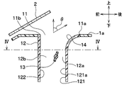
- FIG. 4 is a cross-sectional view taken along line IV-IV in FIG. 3.
- FIG. 4 shows the structure of the air conditioning unit in FIG.
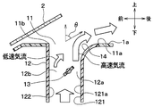
- FIG. 1 is sectional drawing of the air blowing apparatus in FIG. 1 at the time of face mode.
- FIG. 1 is sectional drawing of the air blowing apparatus in FIG. 1 at the time of a defroster mode.
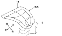
- FIG. 1 is a schematic diagram of the airflow which blows off from the blower outlet in 1st Embodiment.
- FIG. 6 is a transverse cross-sectional view of a duct in Comparative Example 1.
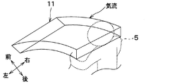
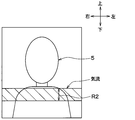
- FIG. It is a schematic diagram of the airflow which blows off from the blower outlet in the comparative example 1. It is a figure which shows the positional relationship of the airflow which blows off from the blower outlet in the comparative example 1, and a passenger
- the air blowing device is applied to an air outlet and a duct of an air conditioning unit mounted in front of the vehicle.
- the air blowing device 10 includes a blowout port 11, a duct 12, and an airflow deflecting door 13.
- the blower outlet 11 blows air into the vehicle interior space as a target space.
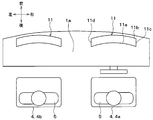
- the blower outlet 11 is located in the windshield 2 side among the upper surface parts 1a of the instrument panel (that is, the instrument panel) 1. In other words, the blower outlet 11 is located in the range which overlaps with the windshield 2 among the upper surface parts 1a, when the windshield 2 is projected in parallel with the up-down direction with respect to the upper surface part 1a.
- the duct 12 connects the air outlet 11 and the air conditioning unit 20.
- the airflow deflection door 13 is located in the duct 12.
- the air conditioning unit 20 is disposed inside the instrument panel 1.
- the instrument panel 1 is an instrument panel provided in front of the passenger compartment, and has an upper surface portion 1a and a design surface portion (that is, a front surface portion) 1b.
- the instrument panel 1 refers to the entire panel located in front of the front seat in the passenger compartment, including not only the part where the instruments are arranged, but also the part that houses the audio and the air conditioner.
- the air outlets 11 are arranged at two locations on the front of the driver seat 4 a and the front of the passenger seat 4 b of the right-hand drive vehicle.
- the blower outlet 11 of the front of the driver's seat 4a is demonstrated, the blower outlet 11 arrange
- the air outlet 11 is elongated in the vehicle width direction (that is, the vehicle left-right direction). That is, the longitudinal direction of the opening shape of the air outlet 11 is along the vehicle width direction.
- the length of the blower outlet 11 in the vehicle width direction is the same as the length of the seat 4 in the vehicle width direction. In addition, the length of the blower outlet 11 in the vehicle width direction may be longer than the length of the seat 4 in the vehicle width direction.
- the blower outlet 11 is comprised by the opening edge part 11a, 11b, 11c, 11d formed in the upper surface part 1a of the instrument panel 1.
- the upper surface portion 1a constitutes a wall portion in which the air outlet 11 having the opening edge portions 11a to 11d extending in one direction (that is, the left-right direction) is formed.
- the opening edge portions 11a to 11d have a pair of long sides 11a and 11b and a pair of short sides 11c and 11d on the surface of the upper surface portion 1a.
- the pair of long sides 11a and 11b are located on the rear side and the front side, respectively, and extend in the left-right direction.
- the pair of short sides 11c and 11d connects the ends of the pair of long sides 11a and 11b.
- the pair of long sides 11 a and 11 b are curved so as to protrude rearward, that is, from the seat 4 on which the occupant 5 is seated.
- the blowout port 11 switches the three blowout modes of the defroster mode, the upper vent mode, and the face mode by the air flow deflecting door 13, and blows out the temperature-adjusted air into the vehicle interior space as the target space.
- the defroster mode air is blown out toward the windshield 2 to clear the cloudiness of the window.
- the face mode air is blown out toward the upper half of the front seat occupant 5.
- the upper vent mode air is blown out upward than in the face mode, and the rear seat passenger is blown.
- the air outlet 11 is constituted by an opening formed at the end of the duct 12.
- the duct 12 is connected to the air outlet 11.
- the duct 12 is a flow path forming unit that forms therein an air flow path connected to the air flow upstream side of the air outlet 11.
- the duct 12 is made of a resin that is configured separately from the air conditioning unit 20, and is connected to the air conditioning unit 20.
- the end of the duct 12 on the upstream side of the air flow is connected to the defroster / face opening 30 of the air conditioning unit 20. Therefore, the duct 12 forms an air flow path through which air blown from the air conditioning unit 20 flows.
- the duct 12 may be formed integrally with the air conditioning unit 20.
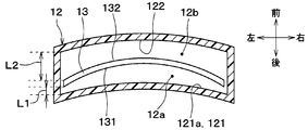
- the duct 12 has a first wall (that is, the rear wall) 121 located on the rear side and a second wall (that is, the front wall) 122 located on the front side.
- the first wall 121 and the second wall 122 face each other in the front-rear direction. Therefore, in the present embodiment, the front-rear direction corresponds to “the direction in which the first wall 121 and the second wall 122 face each other”. Further, the left-right direction corresponds to the “direction intersecting the direction in which the first wall 121 and the second wall 122 face each other”.
- the direction from the front to the rear corresponds to the “direction from the second wall 122 to the first wall 121”.
- the direction from the rear to the front corresponds to the “direction from the first wall 121 to the second wall 122”.
- the first wall 121 is connected to the long side 11a on the rear side of the opening edge of the air outlet 11 shown in FIG.
- the second wall 122 continues to the long side 11b on the front side of the opening edge of the air outlet 11 shown in FIG.
- the airflow deflecting door 13 is an airflow deflecting member that generates two airflows having different flow velocities in the duct 12.
- the airflow deflection door 13 changes the speed of each airflow in the first flow path 12a and the second flow path 12b inside the duct 12.
- the first flow path 12 a is formed between the airflow deflecting door 13 and the first wall 121 of the duct 12.
- the second flow path 12 b is formed between the airflow deflecting door 13 and the second wall 122 of the duct 12.
- a butterfly door is adopted as the airflow deflecting door 13.
- the butterfly door includes a plate-like door main body and a rotary shaft provided at the center of the door main body.
- the rotation axis is arranged in parallel to the longitudinal direction of the air outlet 11 (that is, the vehicle left-right direction). For this reason, the airflow deflection door 13 rotates with the longitudinal direction of the air outlet 11 as the axis.
- the vehicle front-rear direction length of the door main body is smaller than the width of the duct 12 in the vehicle front-rear direction. For this reason, even if the airflow deflecting door 13 is leveled, the duct 12 is not closed.
- the rotation axis is located on the vehicle rear side with respect to the center of the duct 12 in the vehicle front-rear direction. This is because the cross-sectional area of the first flow path 12a is reduced to form a high-speed air flow in the first flow path 12a.
- the first wall 121 of the duct 12 has a guide wall 14 at a portion on the outlet 11 side.
- a part of the first wall 121 on the outlet 11 side constitutes the guide wall 14.
- the guide wall 14 is continuous with the upper surface portion 1 a of the instrument panel 1.
- the guide wall 14 guides the air to be blown out rearward from the outlet 11 by bending the flow direction of the high-speed airflow inside the duct 12 along the wall surface by the Coanda effect, and then bending it toward the rear side.
- the guide wall 14 guides the air flowing through the air flow path so as to blow out from the outlet in the direction from the second wall 122 toward the first wall 121.
- the guide wall 14 By the guide wall 14, the flow path width in the air outlet 11 side portion of the duct 12, that is, the interval between the first wall 121 and the second wall 122 is widened toward the downstream side of the air flow.
- the guide wall 14 is curved so that the wall surface is convex toward the inside of the duct 12.
- the guide wall 14 is curved so as to be separated from the second wall 122 from the portion 121a on the upstream side of the air flow with respect to the portion on the outlet 11 side of the first wall 121, and the opening edge.
- the long side (that is, the side part) 11a which comprises a part is continued.
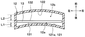
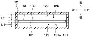
- FIG. 4 is a cross-sectional view of the duct 12 cut along a plane crossing the air flow at a position between the air flow deflecting door 13 and the guide wall 14 in the air flow direction (that is, the vehicle vertical direction). It is the figure seen from.
- the first wall 121 and the second wall 12 of the duct 12 are located on the upstream side of the guide wall 14 in the duct 12 and facing the airflow deflecting door 13 in the vehicle longitudinal direction.
- the wall 122 Similar to the pair of long sides 11a and 11b, the wall 122 has a convex curved shape from the rear to the front, and is smoothly bent.
- first end portion (that is, the rear end portion) 131 on the first wall 121 side and the second end portion (that is, the front end portion) 132 on the second wall 122 side of the airflow deflection door 13 are the left and right sides of the vehicle.
- the air conditioning unit 20 has an air conditioning casing 21 that constitutes an outer shell.
- the air conditioning casing 21 constitutes an air passage that guides air to the vehicle interior, which is the air conditioning target space.
- an inside air inlet 22 for sucking air inside the vehicle interior (that is, inside air) and an outside air inlet 23 for sucking air outside the vehicle compartment (ie, outside air) are formed.
- a suction port opening / closing door 24 for selectively opening / closing the inside air suction port 22 and the outside air suction port 23 is provided at the most upstream part of the air flow of the air conditioning casing 21.
- the inside air inlet 22, the outside air inlet 23, and the inlet opening / closing door 24 constitute an inside / outside air switching unit that switches the intake air into the air conditioning casing 21 between the inside air and the outside air.
- the operation of the inlet opening / closing door 24 is controlled by a control signal output from a control device (not shown).
- a blower 25 as a blower that blows air into the passenger compartment is disposed on the downstream side of the air flow of the suction opening / closing door 24.
- the blower 25 of the present embodiment is an electric blower that drives the centrifugal multiblade fan 25a by an electric motor 25b that is a drive source, and the number of rotations (that is, the amount of blown air) is determined by a control signal output from a control device (not shown). Be controlled.
- An evaporator 26 that functions as a cooler for cooling the air blown by the blower 25 is disposed on the downstream side of the air flow of the blower 25.
- the evaporator 26 is a heat exchanger that exchanges heat between the refrigerant flowing through the inside and the air, and constitutes a vapor compression refrigeration cycle together with a compressor, a condenser, an expansion valve, and the like (not shown).
- a heater core 27 that functions as a heater for heating the air cooled by the evaporator 26 is disposed on the downstream side of the air flow of the evaporator 26.
- the heater core 27 of the present embodiment is a heat exchanger that heats air using the cooling water of the vehicle engine as a heat source.
- the evaporator 26 and the heater core 27 constitute a temperature adjusting unit that adjusts the temperature of the air blown into the vehicle interior.
- a cold air bypass passage 28 is formed on the downstream side of the air flow of the evaporator 26 to allow the air after passing through the evaporator 26 to flow around the heater core 27.
- the temperature of the air mixed on the downstream side of the air flow of the heater core 27 and the cold air bypass passage 28 varies depending on the air volume ratio of the air passing through the heater core 27 and the air passing through the cold air bypass passage 28.
- an air mix door 29 is arranged on the downstream side of the air flow of the evaporator 26 and on the inlet side of the heater core 27 and the cold air bypass passage 28.
- the air mix door 29 continuously changes the air volume ratio of the cold air flowing into the heater core 27 and the cold air bypass passage 28, and functions as a temperature adjusting unit together with the evaporator 26 and the heater core 27.
- the operation of the air mix door 29 is controlled by a control signal output from the control device.
- a defroster / face opening 30 and a foot opening 31 are provided at the most downstream part of the air flow of the air conditioning casing 21.
- the defroster / face opening 30 is connected to the air outlet 11 provided in the upper surface 1 a of the instrument panel 1 through the duct 12.
- the foot opening 31 is connected to the foot outlet 33 via the foot duct 32.
- a defroster / face door 34 for opening and closing the defroster / face opening 30 is disposed on the upstream side of the air flow of the defroster / face opening 30.
- a foot door 35 that opens and closes the foot opening 31 is disposed on the upstream side of the air flow of the foot opening 31.
- the defroster / face door 34 and the foot door 35 are blowing mode doors for switching the blowing state of the air blown into the vehicle interior.
- the airflow deflecting door 13 operates in conjunction with these blowing mode doors 34 and 35 so as to be in a desired blowing mode.
- the operations of the air flow deflecting door 13 and the blowing mode doors 34 and 35 are controlled by a control signal output from the control device. Note that the airflow deflecting door 13 and the blowing mode doors 34 and 35 can be changed in position by a passenger's manual operation.
- the defroster / face door 34 closes the defroster / face opening 30 and the foot door 35 opens the foot opening 31.
- the defroster / face door 34 opens the defroster / face opening 30 and the foot door 35 closes the foot opening 31.
- the position of the airflow deflecting door 13 is a position corresponding to a desired blowing mode.
- the velocity of each of the airflow passing through the first flow path 12a and the airflow passing through the second flow path 12b is changed by rotating the airflow deflecting door 13.
- the blowing angle ⁇ is changed.
- the blowing angle ⁇ here is an angle formed by the blowing direction with respect to the vertical direction as shown in FIG.
- the vertical direction is used as a reference because the direction of the airflow passing between the portion 121a upstream of the guide wall 14 and the second wall 122 of the first wall 121 from the guide wall 14 is from bottom to top. Because it is the direction to go.
- the direction of the airflow deflecting door 13 is the direction shown in FIG. That is, the door body portion of the airflow deflecting door 13 is tilted so that the cross-sectional area of the first flow path 12a decreases as the air flow direction proceeds.
- the cross-sectional area of the first flow path 12a is smaller than the cross-sectional area of the second flow path 12b, and a high-speed air flow is generated in the first flow path 12a and a low-speed air flow is generated in the second flow path 12b. It will be in the 1st state.
- the airflow is constricted when the airflow passes through the first flow path 12a, which is a factor in generating a high-speed airflow in the first flow path 12a.
- the cross-sectional area of the first flow path 12a means the area of the cross section that crosses the air flow of the first flow path 12a.
- the cross-sectional area of the second flow path 12b means an area of a cross section that crosses the air flow of the first flow path 12a.
- the high-speed airflow generated in the first flow path 12a means a higher-speed airflow than the airflow generated in the second flow path 12b.
- the low-speed airflow generated in the second flow path 12b means a low-speed airflow than the airflow generated in the first flow path 12a.
- the blowing angle ⁇ in the face mode can be set to an arbitrary angle.
- the direction of the air flow deflecting door 13 is the direction shown in FIG. That is, the door main body portion of the airflow deflecting door 13 is tilted so that the cross-sectional area of the second flow path 12b formed between the airflow deflecting door 13 and the second wall 122 decreases as the air flows in the air flow direction. .
- a high speed air flow is generated in the second flow path 12b and a low speed air flow is generated in the first flow path 12a.
- the high-speed airflow flows upward along the second wall 122 of the duct 12.
- the direction of the merged airflow is directed from the outlet 11 directly above or obliquely forward.
- air whose temperature has been adjusted by the air conditioning unit 20, for example, warm air is blown out from the air outlet 11 toward the windshield 2.
- the direction of the air flow deflecting door 13 may be the direction in which the door main body is parallel to the vertical direction.
- the airflow in the first flow path 12a and the airflow in the second flow path 12b have the same speed.
- the velocity of the airflow in the first flow path 12a is smaller than that in the face mode. For this reason, the direction of the air which blows off from the blower outlet 11 turns into the direction which goes from the blower outlet 11 right above or diagonally back.
- the blowing mode when the blowing mode is the upper vent mode, the direction of the airflow deflecting door 13 is the direction between the face mode and the defroster mode. In this case as well, the first state is entered, but since the high-speed airflow is slower than in the face mode, the blowing angle ⁇ is smaller than in the face mode. As a result, air whose temperature has been adjusted by the air conditioning unit 20, for example, cold air, is blown out from the air outlet 11 toward the rear seat occupant.
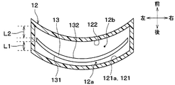
- the first wall 121 and the second wall 122 of the duct 12 are convexly curved from the rear to the front.
- the first end 131 and the second end 132 of the airflow deflecting door 13 have a linear shape extending in the vehicle left-right direction.
- the shape of the 1st wall 121 and the 2nd wall 122 here is a shape of the part which faces the air flow deflection door 13 at least in the front-back direction.
- the first end 131 of the airflow deflection door 13 is the end of the airflow deflection door 13 that is located closest to the first wall 121 in the face mode.
- the second end portion 132 of the airflow deflecting door 13 is an end portion of the airflow deflecting door 13 located closest to the second wall 122 in the face mode.
- the widths of the first flow path 12a and the second flow path 12b in the vehicle front-rear direction are the first flow path width L1 and the second flow path width L2, at both ends of the duct 12 in the left-right direction of the vehicle.
- the first flow path width L1 is wider than the first flow path width L1 at the center. More specifically, the first flow path width L1 is gradually increased from the center to both ends.
- the second flow path width L2 at both ends of the duct 12 in the left-right direction of the vehicle is narrower than the second flow path width L2 at the center. More specifically, the second flow path width L2 is gradually narrowed from the center to both ends.
- the ratio of the first flow path width L1 to the second flow path width L2 is gradually increased from the central portion in the left-right direction of the duct 12 toward both ends.
- said 1st flow path width L1 and said 2nd flow path width L2 are width
- the first flow path width L1 is a distance between the first wall 121 and the airflow deflecting door 13 in the vehicle front-rear direction.
- the second flow path width L2 is the distance between the airflow deflecting door 13 and the second wall 122 in the vehicle front-rear direction.
- the vehicle longitudinal direction corresponds to one specific direction that intersects each of the first wall, the second wall, and the airflow deflecting member.
- the position of the central portion in the left-right direction of the duct 12 and one position of both end portions correspond to a first position and a second position that are different from each other in the longitudinal direction of the air flow path.
- the ratio between the first flow path width L1 and the second flow path width L2 is different.
- the bend angle is different.
- the smaller the ratio of the first flow path width L1 to the second flow path width L2 the higher the speed of the high-speed airflow and the lower the speed of the low-speed airflow, that is, the high-speed airflow and the low-speed airflow.
- the bending angle ⁇ becomes large.
- the larger the ratio of the first flow path width L1 to the second flow path width L2 the smaller the speed difference between the high-speed air flow and the low-speed air flow and the smaller the bending angle ⁇ .
- the bending angle ⁇ of the air blown from the blower outlet 11 gradually decreases as it goes from the central portion in the left-right direction of the blower outlet 11 toward both ends.
- the shape of the airflow toward the occupant is a U-shape that protrudes downward as seen from the direction in which the airflow proceeds in the opposite direction as shown in FIG. That is, the central part in the left-right direction of the airflow has a convex shape that is convex downward.
- the airflow can be applied over a wide range R ⁇ b> 1 in the vertical direction at both end portions in the horizontal direction of the occupant 5.
- the shape of the airflow is a shape that extends linearly in the left-right direction except for both ends in the left-right direction.
- the airflow strikes a narrow range R2 in the vertical direction at any position in the horizontal direction of the occupant.
- the shape of the airflow toward the occupant can be formed in a U-shape that protrudes downward, and can be made different from the airflow in the comparative example 1.
- the shape of the airflow that has a curved portion can expand the vertical range in which the airflow hits the occupant, rather than the case where the shape of the airflow is linear in the lateral direction.
- the shape of the airflow described above refers to the shape of the main stream blown out from the air outlet 11.
- the present embodiment is different from the first embodiment in the shape of the first wall 121 and the second wall 122 of the duct 12 and the shape of the air flow deflecting door 13.
- Other configurations are the same as those of the first embodiment.
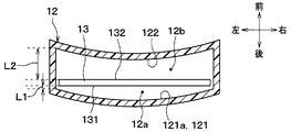
- the first wall 121 and the second wall 122 of the duct 12 are linear shapes extending in the left-right direction in the transverse section of the duct 12. That is, it is a planar shape extending in the left-right direction.
- the first end portion 131 and the second end portion 132 of the airflow deflection door 13 have a convex curved shape from the front to the rear.
- the first flow path width L1 is gradually increased from the central portion in the left-right direction toward both ends.
- the second flow path width L2 is gradually narrowed from the center in the left-right direction toward both ends. Therefore, the ratio of the first flow path width L1 to the second flow path width L2 is gradually increased from the central portion in the left-right direction of the duct 12 toward both ends. For this reason, also by this embodiment, the shape of an airflow can be made into the shape similar to 1st Embodiment, and the effect similar to 1st Embodiment is acquired.
- the present embodiment is different from the first embodiment in the shape of the airflow deflection door 13.
- Other configurations are the same as those of the first embodiment.
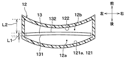
- first wall 121 and the second wall 122 of the duct 12 have a curved shape that is convex from the rear to the front.
- the first end portion 131 and the second end portion 132 of the airflow deflection door 13 have a convex curved shape from the front to the rear.
- the first flow path width L1 is gradually increased from the central portion in the left-right direction toward both ends.
- the second flow path width L2 is gradually narrowed from the center in the left-right direction toward both ends. Therefore, the ratio of the first flow path width L1 to the second flow path width L2 is gradually increased from the central portion in the left-right direction of the duct 12 toward both ends. For this reason, also by this embodiment, the shape of an airflow can be made into the shape similar to 1st Embodiment, and the effect similar to 1st Embodiment is acquired.
- the present embodiment is different from the first embodiment in the shapes of the first wall 121 and the second wall 122 of the duct 12 and the shape of the airflow deflecting door 13. Other configurations are the same as those of the first embodiment.
- the first wall 121 and the second wall 122 of the duct 12 have a curved shape that is convex from the front to the rear.
- the first end portion 131 and the second end portion 132 of the airflow deflection door 13 have a convex curved shape from the front to the rear.
- the first end portion 131 and the second end portion 132 of the airflow deflecting door 13 have a curvature that is tighter than that of the first wall 121 and the second wall 122.
- the first flow path width L1 is gradually increased from the central portion in the left-right direction toward both ends.
- the second flow path width L2 is gradually narrowed from the center in the left-right direction toward both ends. Therefore, the ratio of the first flow path width L1 to the second flow path width L2 is gradually increased from the central portion in the left-right direction of the duct 12 toward both ends. For this reason, also by this embodiment, the shape of an airflow can be made into the shape similar to 1st Embodiment, and the effect similar to 1st Embodiment is acquired.
- the present embodiment is different from the first embodiment in the shape of the first wall 121 and the second wall 122 of the duct 12 and the shape of the airflow deflecting door 13, and the shape of the airflow is the same. This is different from the first embodiment.
- Other configurations are the same as those of the first embodiment.
- the first wall 121 and the second wall 122 of the duct 12 have a curved shape that is convex from the front to the rear.
- the first end 131 and the second end 132 of the airflow deflecting door 13 have a linear shape extending in the left-right direction.
- the first flow path width L1 is gradually narrowed from the central portion in the left-right direction of the duct 12 toward both ends.
- the second flow path width L2 is gradually increased from the central portion in the left-right direction of the duct 12 toward both ends.
- the ratio of the first flow path width L1 to the second flow path width L2 is gradually reduced from the central portion in the left-right direction of the duct 12 toward both ends.
- the ratio of the first flow path width L1 to the second flow path width L2 is gradually increased from both ends of the duct 12 in the left-right direction toward the center.
- one position and a center position at both ends in the left-right direction of the duct 12 correspond to a first position and a second position that are different from each other in the longitudinal direction of the air flow path.
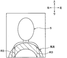
- the bending angle ⁇ of the air blown out from the air outlet 11 gradually increases as it goes from the central portion in the left-right direction of the air outlet 11 toward both ends.
- the shape of the airflow toward the occupant is a U-shape that is upwardly convex as seen from the direction in which the airflow proceeds in the opposite direction, as shown in FIG. That is, the central part in the left-right direction of the airflow is convex upward.
- the airflow can be applied over a wide range R ⁇ b> 3 in the vertical direction at both end portions in the left-right direction of the occupant 5.
- the present embodiment is different from the fifth embodiment in the shape of the first wall 121 and the second wall 122 of the duct 12 and the shape of the airflow deflecting door 13.
- Other configurations are the same as those of the first embodiment.
- first wall 121 and the second wall 122 of the duct 12 have a planar shape extending along the left-right direction.
- the first end portion 131 and the second end portion 132 of the airflow deflecting door 13 have a convex curved shape from the rear to the front.
- the first flow path width L1 is gradually narrowed from the central portion in the left-right direction of the duct 12 toward both ends.
- the second flow path width L2 is gradually increased from the central portion in the left-right direction of the duct 12 toward both ends. Therefore, the ratio of the first flow path width L1 to the second flow path width L2 is gradually reduced from the central portion in the left-right direction of the duct 12 toward both ends.
- the shape of the airflow can be a U-shape that is convex upward as in the fifth embodiment, and the same effect as in the first embodiment can be obtained.
- the present embodiment is different from the fifth embodiment in the shape of the airflow deflection door 13.
- Other configurations are the same as those of the first embodiment.
- first wall 121 and the second wall 122 of the duct 12 have a curved shape that is convex from the front to the rear.
- the first end portion 131 and the second end portion 132 of the airflow deflecting door 13 have a convex curved shape from the rear to the front.
- the first flow path width L1 is gradually narrowed from the central portion in the left-right direction of the duct 12 toward both ends.
- the second flow path width L2 is gradually increased from the central portion in the left-right direction of the duct 12 toward both ends. Therefore, the ratio of the first flow path width L1 to the second flow path width L2 is gradually reduced from the central portion in the left-right direction of the duct 12 toward both ends.
- the shape of the airflow can be a U-shape that is convex upward as in the fifth embodiment, and the same effect as in the first embodiment can be obtained.
- the present embodiment is different from the fifth embodiment in the shapes of the first wall 121 and the second wall 122 of the duct 12 and the shape of the airflow deflecting door 13.
- Other configurations are the same as those of the first embodiment.
- the first wall 121 and the second wall 122 of the duct 12 have a curved shape that is convex from the rear to the front.
- the first end portion 131 and the second end portion 132 of the airflow deflecting door 13 have a convex curved shape from the rear to the front. Further, the first end portion 131 and the second end portion 132 of the airflow deflecting door 13 have a curvature that is tighter than that of the first wall 121 and the second wall 122.
- the first flow path width L1 is gradually narrowed from the central portion in the left-right direction of the duct 12 toward both ends.
- the second flow path width L2 is gradually increased from the central portion in the left-right direction of the duct 12 toward both ends. Therefore, the ratio of the first flow path width L1 to the second flow path width L2 is gradually reduced from the central portion in the left-right direction of the duct 12 toward both ends.
- the shape of the airflow can be a U-shape that is convex upward as in the fifth embodiment, and the same effect as in the first embodiment can be obtained.
- the present embodiment is different from the first embodiment in the shape of the first wall 121 and the second wall 122 of the duct 12 and the shape of the air flow deflecting door 13.
- Other configurations are the same as those of the first embodiment.
- the first wall 121 and the second wall 122 of the duct 12 have a planar shape extending in the left-right direction.
- the second end 132 of the airflow deflecting door 13 has a linear shape extending in the left-right direction.
- the first end 131 of the air flow deflecting door 13 has a curved shape in which the left end is located on the front side of the right end and is convex from the rear to the front. In other words, the distance between the first end 131 of the airflow deflecting door 13 and the first wall 121 gradually decreases from left to right (that is, from the vehicle center side to the window side in the left-right direction). It has an oblique shape with respect to the left-right direction.
- the ratio of the first flow path width L1 to the second flow path width L2 is from one of the left and right ends of the duct 12 to the other, that is, from the left end of the duct 12 to the right end. It is getting smaller gradually.
- the bending angle ⁇ of the air blown out from the air outlet 11 gradually increases as it goes from the left end portion in the left-right direction of the air outlet 11 toward the right end portion.
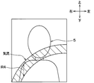
- the shape of the airflow toward the occupant is a U-shaped right-side shape that is convex upward as seen from the direction of the airflow. That is, the shape of the airflow is a curved shape in which the left end portion of the airflow is located on the upper side, the right end portion of the airflow is located on the lower side, and the central portion in the left-right direction of the airflow is convex upward.
- the airflow hits over a wide range R4 in the vertical direction.
- the occupant 5 of the driver's seat 4a increases the temperature of the right part of the body due to solar radiation from the right window of the driver's seat 4a.
- cold air can be applied to a wide range in the vertical direction on the window side portion of the occupant's upper body in the face mode. For this reason, a passenger
- the shape of the first wall 121 and the second wall 122 of the duct 12 and the shape of the airflow deflecting door 13 are such that the ratio of the first flow path width L1 to the second flow path width L2 is from the right end of the duct 12. The shape becomes gradually smaller toward the left end. Thereby, the same effect as this embodiment is acquired.
- the present embodiment is different from the ninth embodiment in the shapes of the first wall 121 and the second wall 122 of the duct 12 and the shape of the airflow deflecting door 13.
- Other configurations are the same as those of the first embodiment.
- the first end 131 and the second end 132 of the airflow deflecting door 13 have a linear shape extending in the left-right direction.
- the second wall 122 of the duct 12 has a planar shape extending in the left-right direction.
- the first wall 121 of the duct 12 has a curved shape in which the right end is located on the front side of the left end and is convex from the rear to the front. In other words, the first wall 121 of the duct 12 has an oblique shape with respect to the left-right direction so that the distance from the first end 131 of the airflow deflection door 13 gradually decreases from left to right. It has become.
- the ratio of the first flow path width L1 to the second flow path width L2 is gradually decreased from the left end portion of the duct 12 toward the right end portion. ing. Thereby, the same effect as in the ninth embodiment can be obtained.
- the left and right relations may be interchanged in the present embodiment.
- the present embodiment is different from the first embodiment in the shape of the first wall 121 and the second wall 122 of the duct 12 and the shape of the air flow deflecting door 13.
- FIG. 26 corresponds to FIG. Other configurations are the same as those of the first embodiment.
- the second flow path width L2 is uniform throughout the longitudinal direction of the cross section of the duct 12 (that is, the left-right direction of the duct 12).
- the first flow path width L1 at both ends A1 and A2 in the longitudinal direction of the cross section of the duct 12 is uniform, and the first flow path width L1 over the entire predetermined range A3 on the center side of both ends A1 and A2. Is uniform.
- both the 1st flow path width L1 in both ends A1 and A2 and the 1st flow path width L1 in the predetermined range A3 are narrower than the 2nd flow path width L2.
- the first flow path width L1 at both ends A1 and A2 is narrower than the first flow path width L1 in the predetermined range A3.
- the ratio of the first flow path width L1 to the second flow path width L2 is uniform within the predetermined range A3 on the center side. Further, the ratio of the first flow path width L1 to the second flow path width L2 is smaller in the both end portions A1 and A2 than in the predetermined range A3 on the center side. In the present embodiment, either one of the both end portions A1 and A2 and one position within the predetermined range A3 are respectively different from each other in the first position and the second position in the longitudinal direction of the air flow path. Equivalent to. Therefore, also in the present embodiment, the ratio between the first flow path width and the second flow path width is different between the first position and the second position.
- the present inventor manufactured an air blowing device having a uniform ratio of the first flow path width and the second flow path width in the entire left and right direction of the duct 12.
- the shape of the air flow blown out from the air outlet becomes the shape indicated by the broken line in FIG. 27, and there is a problem that the shape does not extend linearly in the entire longitudinal direction of the air outlet (that is, the vehicle left-right direction). It was issued. This is because the airflow is less likely to bend at both ends in the longitudinal direction of the air outlet due to the influence of the side wall of the duct 12.
- the ratio of the first flow path width L1 to the second flow path width L2 at both ends A1 and A2 is set to the first flow with respect to the second flow path width L2 in the predetermined range A3 on the center side. It is smaller than the ratio of the road width L1.
- the airflow flowing through both ends in the longitudinal direction in the cross section of the duct 12 is reduced.
- the speed can be increased, and the bending angle of the airflow can be increased.
- the shape of the airflow when the airflow blown out from the air outlet is viewed from the opposite direction of the air current, the shape indicated by the solid line in FIG. It becomes possible to make it the shape extended linearly in the whole region.
- the shapes of the first wall 121 and the second wall 122 of the duct 12 and the shape of the airflow deflecting door 13 are not limited to the shapes shown in FIG.
- the ratio of the first flow path width L1 to the second flow path width L2 is uniform within the predetermined range A3 on the center side, and both ends A1 and A2 are more than the predetermined range A3 on the center side. If the shape satisfies the relationship that the ratio of the first flow path width L1 to the second flow path width L2 is small, the same effect as the present embodiment can be obtained.
- the ratio of the first flow path width L1 to the second flow path width L2 is gradually changed, but may be changed stepwise.
- the ratio of the first flow path width L1 to the second flow path width L2 only needs to increase from the central portion in the left-right direction of the duct 12 toward both ends.
- the bending angle of the airflow at both ends of the outlet is smaller than the bending angle of the airflow at the center of the outlet.
- the shape of the airflow when the airflow blown out from the air outlet is viewed from the direction in which the airflow is counter-traveling can be a shape similar to a downwardly convex U-shape or V-shape.
- the ratio of the first flow path width L1 to the second flow path width L2 only needs to decrease from the central portion in the left-right direction of the duct 12 toward both ends.
- the bending angle of the airflow at both ends of the air outlet is larger than the bending angle of the airflow at the center of the air outlet.
- the shape of the airflow when the airflow blown out from the air outlet is viewed from the counter-propagating direction of the airflow can be a shape similar to an upwardly convex U-shape or V-shape.
- the ratio of the first flow path width L1 to the second flow path width L2 only needs to decrease as it goes from one end of the left and right ends of the duct 12 to the other.
- the bending angle of the airflow on the other side of the both ends of the outlet is larger than the bending angle of the airflow on one side of the both ends of the outlet.
- the shape of the airflow when the airflow blown out from the air outlet is seen from the counter-traveling direction of the airflow can be made to be a shape on the left and right sides of a shape similar to a U-shape or V-shape.
- the ratio of the first flow path width L1 to the second flow path width L2 may be different at any two positions that are different in the left-right direction of the duct 12. Thereby, the shape of the airflow blown out from the air outlet can be changed to a shape different from the case of Comparative Example 1.
- the ratio of the first flow path width L1 to the second flow path width L2 only needs to be increased by moving from one of two arbitrary positions that differ in the left-right direction of the duct 12 to the other. . Thereby, the shape of the airflow blown out from the air outlet can be changed to a shape different from the case of Comparative Example 1.
- the butterfly door is adopted as the airflow deflecting door 13, but another door such as a slide door may be adopted.
- the position of the air flow deflecting door 13 is set to a position where the cross-sectional area of the first flow path 12a is smaller than the cross-sectional area of the second flow path 12b.
- the air blowing device of the present disclosure is applied to the air outlet 11 of the upper surface portion 1a of the instrument panel 1.
- the air blowing device of the present disclosure is applied to the air outlet of the lower surface of the instrument panel 1 ( That is, you may apply to a foot blower outlet. In this case, the blowing angle of the air blown from the foot outlet can be arbitrarily changed.
- the air blowing apparatus of this indication was applied to the vehicle air conditioner, you may apply the air blowing apparatus of this indication to air conditioners other than a vehicle.
- the first flow path width L1 is the distance between the first wall 121 and the airflow deflecting member 13 in the vehicle longitudinal direction.
- the second flow path width L2 is in the vehicle longitudinal direction. This is the distance between the airflow deflecting member 13 and the second wall 122.
- the direction when the first flow path width L1 and the second flow path width L2 are measured is not limited to the vehicle front-rear direction.
- the direction when the first flow path width L1 and the second flow path width L2 are measured may be a direction oblique to the vehicle front-rear direction.
- the direction when the first flow path width L1 and the second flow path width L2 are measured may be one specific direction that intersects each of the first wall, the second wall, and the airflow deflecting member. That is, when comparing the ratio of the first flow path width and the second flow path width at the first position and the second position, which are different in the left-right direction of the duct 12, the first flow measured in the same direction.
- the road width and the second flow path width may be used.
Landscapes
- Engineering & Computer Science (AREA)
- Mechanical Engineering (AREA)
- Physics & Mathematics (AREA)
- Thermal Sciences (AREA)
- Chemical & Material Sciences (AREA)
- Combustion & Propulsion (AREA)
- General Engineering & Computer Science (AREA)
- Air-Conditioning For Vehicles (AREA)
- Air-Flow Control Members (AREA)
Abstract
Description
空気を吹き出す空気吹出装置は、
対象空間に空気を吹き出す吹出口と、
第1の壁および第1の壁に対向する第2の壁を有し、吹出口の空気流れ上流側に連なる空気流路を内部に形成する流路形成部と、
空気流路に設けられ、空気流路に流速が異なる2つの気流を発生させる気流偏向部材とを備え、
吹出口の長手方向、空気流路の空気流れを横切る横断面における空気流路の長手方向および気流偏向部材の長手方向は、いずれも、第1の壁と第2の壁とが対向する方向に交差しており、
空気流路において、気流偏向部材と第1の壁との間を第1流路とし、気流偏向部材と第2の壁との間を第2流路とし、第1の壁と第2の壁とが対向する方向における第1流路と第2流路のそれぞれの幅を第1流路幅と第2流路幅としたとき、
気流偏向部材は、第1流路に高速の気流が発生するとともに、第2流路に低速の気流が発生するように構成されており、
第1の壁のうち吹出口側の一部は、気流偏向部材が発生させた第1流路からの高速の気流を壁面に沿わせて曲げて、高速の気流の向きを第2の壁から第1の壁に向かう方向とするように、高速の気流をガイドするガイド壁を構成し、
空気流路の長手方向で互いに異なる第1の位置と第2の位置において、第1流路幅と第2流路幅との比が異なっている。
空気を吹き出す空気吹出装置は、
対象空間に空気を吹き出す吹出口と、
第1の壁および第1の壁に対向する第2の壁を有し、吹出口の空気流れ上流側に連なる空気流路を内部に形成する流路形成部と、
空気流路に設けられ、空気流路に流速が異なる2つの気流を発生させる気流偏向部材とを備え、
吹出口の長手方向、空気流路の空気流れを横切る横断面における空気流路の長手方向および気流偏向部材の長手方向は、いずれも、第1の壁と第2の壁とが対向する方向に交差しており、
空気流路は、気流偏向部材と第1の壁との間の第1流路と、気流偏向部材と第2の壁との間の第2流路とを有し、
気流偏向部材は、第1流路の空気流れを横切る横断面の面積を、第2流路の空気流れを横切る横断面の面積よりも小さくすることにより、第1流路に第2流路に発生する気流よりも高速の気流が発生するとともに、第2流路に第1流路に発生する気流よりも低速の気流が発生するように構成されており、
第1の壁のうち吹出口側の一部は、気流偏向部材が発生させた第1流路からの高速の気流を壁面に沿わせて曲げて、高速の気流の向きを第2の壁から第1の壁に向かう方向とするように、高速の気流をガイドするガイド壁を構成し、
気流偏向部材が第1流路の横断面の面積を最小とする状態のときに、第1の壁と第2の壁と気流偏向部材のそれぞれと交差する1つの特定方向における第1の壁と気流偏向部材との距離が第1流路幅であり、特定方向における気流偏向部材と第2の壁との距離が第2流路幅であり、
空気流路の長手方向で互いに異なる第1の位置と第2の位置において、第1流路幅と第2流路幅との比が異なっている。
空気流路の長手方向の両端部よりも中央部側の所定範囲内において、第2流路幅に対する第1流路幅の割合が均一であり、
両端部の方が中央部側の所定範囲よりも、第2流路幅に対する第1流路幅の割合が小さくなっている。
本実施形態では、本開示に係る空気吹出装置を車両の前方に搭載される空調ユニットの吹出口およびダクトに適用している。
図13に示すように、本実施形態は、ダクト12の第1の壁121、第2の壁122の形状および気流偏向ドア13の形状が第1実施形態と相違する。その他の構成は、第1実施形態と同じである。
図14に示すように、本実施形態は、気流偏向ドア13の形状が第1実施形態と相違する。その他の構成は、第1実施形態と同じである。
図15に示すように、本実施形態は、ダクト12の第1の壁121、第2の壁122の形状および気流偏向ドア13の形状が第1実施形態と相違する。その他の構成は、第1実施形態と同じである。
図16に示すように、本実施形態は、ダクト12の第1の壁121、第2の壁122の形状および気流偏向ドア13の形状が第1実施形態と相違するとともに、気流の形状も第1実施形態と相違する。その他の構成は、第1実施形態と同じである。
図19に示すように、本実施形態は、ダクト12の第1の壁121、第2の壁122の形状および気流偏向ドア13の形状が第5実施形態と相違する。その他の構成は、第1実施形態と同じである。
図20に示すように、本実施形態は、気流偏向ドア13の形状が第5実施形態と相違する。その他の構成は、第1実施形態と同じである。
図21に示すように、本実施形態は、ダクト12の第1の壁121、第2の壁122の形状および気流偏向ドア13の形状が第5実施形態と相違する。その他の構成は、第1実施形態と同じである。
図22に示すように、本実施形態は、ダクト12の第1の壁121、第2の壁122の形状および気流偏向ドア13の形状が第1実施形態と相違する。その他の構成は、第1実施形態と同じである。
図25に示すように、本実施形態は、ダクト12の第1の壁121、第2の壁122の形状および気流偏向ドア13の形状が第9実施形態と相違する。その他の構成は、第1実施形態と同じである。
図26に示すように、本実施形態は、ダクト12の第1の壁121、第2の壁122の形状および気流偏向ドア13の形状が第1実施形態と相違する。図26は、図4に対応している。その他の構成は、第1実施形態と同じである。
本開示は上記した実施形態に限定されるものではなく、下記のように、請求の範囲に記載した範囲内において適宜変更が可能である。また、本開示は、上記各実施形態に対する以下のような変形例および均等範囲の変形例も許容される。
Claims (7)
- 空気を吹き出す空気吹出装置であって、
対象空間に空気を吹き出す吹出口(11)と、
第1の壁(121)および前記第1の壁に対向する第2の壁(122)を有し、前記吹出口の空気流れ上流側に連なる空気流路を内部に形成する流路形成部(12)と、
前記空気流路に設けられ、前記空気流路に流速が異なる2つの気流を発生させる気流偏向部材(13)とを備え、
前記吹出口の長手方向、前記空気流路の空気流れを横切る横断面における前記空気流路の長手方向および前記気流偏向部材の長手方向は、いずれも、前記第1の壁と前記第2の壁とが対向する方向に交差しており、
前記空気流路において、前記気流偏向部材と前記第1の壁との間を第1流路(12a)とし、前記気流偏向部材と前記第2の壁との間を第2流路(12b)とし、前記第1の壁と前記第2の壁とが対向する方向における前記第1流路と前記第2流路のそれぞれの幅を第1流路幅(L1)と第2流路幅(L2)としたとき、
前記気流偏向部材は、前記第1流路に高速の気流が発生するとともに、前記第2流路に低速の気流が発生するように構成されており、
前記第1の壁のうち前記吹出口側の一部は、前記気流偏向部材が発生させた前記第1流路からの高速の気流を壁面に沿わせて曲げて、前記高速の気流の向きを前記第2の壁から前記第1の壁に向かう方向とするように、前記高速の気流をガイドするガイド壁(14)を構成し、
前記空気流路の前記長手方向で互いに異なる第1の位置と第2の位置において、前記第1流路幅と前記第2流路幅との比が異なっている空気吹出装置。 - 空気を吹き出す空気吹出装置であって、
対象空間に空気を吹き出す吹出口(11)と、
第1の壁(121)および前記第1の壁に対向する第2の壁(122)を有し、前記吹出口の空気流れ上流側に連なる空気流路を内部に形成する流路形成部(12)と、
前記空気流路に設けられ、前記空気流路に流速が異なる2つの気流を発生させる気流偏向部材(13)とを備え、
前記吹出口の長手方向、前記空気流路の空気流れを横切る横断面における前記空気流路の長手方向および前記気流偏向部材の長手方向は、いずれも、前記第1の壁と前記第2の壁とが対向する方向に交差しており、
前記空気流路は、前記気流偏向部材と前記第1の壁との間の第1流路(12a)と、前記気流偏向部材と前記第2の壁との間の第2流路(12b)とを有し、
前記気流偏向部材は、前記第1流路の空気流れを横切る横断面の面積を、前記第2流路の空気流れを横切る横断面の面積よりも小さくすることにより、前記第1流路に前記第2流路に発生する気流よりも高速の気流が発生するとともに、前記第2流路に前記第1流路に発生する気流よりも低速の気流が発生するように構成されており、
前記第1の壁のうち前記吹出口側の一部は、前記気流偏向部材が発生させた前記第1流路からの高速の気流を壁面に沿わせて曲げて、前記高速の気流の向きを前記第2の壁から前記第1の壁に向かう方向とするように、前記高速の気流をガイドするガイド壁(14)を構成し、
前記気流偏向部材が前記第1流路の前記横断面の面積を最小とする状態のときに、前記第1の壁と前記第2の壁と前記気流偏向部材のそれぞれと交差する1つの特定方向における前記第1の壁と前記気流偏向部材との距離が第1流路幅(L1)であり、前記特定方向における前記気流偏向部材と前記第2の壁との距離が第2流路幅(L2)であり、
前記空気流路の前記長手方向で互いに異なる第1の位置と第2の位置において、前記第1流路幅と前記第2流路幅との比が異なっている空気吹出装置。 - 前記第2流路幅に対する前記第1流路幅の割合が、前記第1の位置から前記第2の位置に向かうにつれて、大きくなっている請求項1または2に記載の空気吹出装置。
- 前記第2流路幅に対する前記第1流路幅の割合が、前記空気流路の前記長手方向の中央部から両端部に向かうにつれて、大きくなっている請求項1または2に記載の空気吹出装置。
- 前記第2流路幅に対する前記第1流路幅の割合が、前記空気流路の前記長手方向の中央部から両端部に向かうにつれて、小さくなっている請求項1または2に記載の空気吹出装置。
- 前記第2流路幅に対する前記第1流路幅の割合が、前記空気流路の前記長手方向の両端部の一方から他方に向かうにつれて、小さくなっている請求項1または2に記載の空気吹出装置。
- 前記空気流路の前記長手方向の両端部(A1、A2)よりも中央部側の所定範囲(A3)内において、前記第2流路幅に対する前記第1流路幅の割合が均一であり、
前記両端部の方が前記中央部側の所定範囲よりも、前記第2流路幅に対する前記第1流路幅の割合が小さくなっている請求項1または2に記載の空気吹出装置。
Priority Applications (2)
| Application Number | Priority Date | Filing Date | Title |
|---|---|---|---|
| JP2017509469A JP6399211B2 (ja) | 2015-03-27 | 2016-03-08 | 空気吹出装置 |
| DE112016001442.2T DE112016001442T5 (de) | 2015-03-27 | 2016-03-08 | Luftausblas-Einrichtung |
Applications Claiming Priority (2)
| Application Number | Priority Date | Filing Date | Title |
|---|---|---|---|
| JP2015066819 | 2015-03-27 | ||
| JP2015-066819 | 2015-03-27 |
Publications (1)
| Publication Number | Publication Date |
|---|---|
| WO2016158253A1 true WO2016158253A1 (ja) | 2016-10-06 |
Family
ID=57004522
Family Applications (1)
| Application Number | Title | Priority Date | Filing Date |
|---|---|---|---|
| PCT/JP2016/057233 Ceased WO2016158253A1 (ja) | 2015-03-27 | 2016-03-08 | 空気吹出装置 |
Country Status (3)
| Country | Link |
|---|---|
| JP (1) | JP6399211B2 (ja) |
| DE (1) | DE112016001442T5 (ja) |
| WO (1) | WO2016158253A1 (ja) |
Cited By (1)
| Publication number | Priority date | Publication date | Assignee | Title |
|---|---|---|---|---|
| JP2025141726A (ja) * | 2024-03-15 | 2025-09-29 | 株式会社エアー・トラスト | 湾曲型gw製ラインボックス |
Citations (6)
| Publication number | Priority date | Publication date | Assignee | Title |
|---|---|---|---|---|
| JPS6227863U (ja) * | 1985-08-02 | 1987-02-20 | ||
| JPH01172909U (ja) * | 1988-05-25 | 1989-12-07 | ||
| JPH07324802A (ja) * | 1994-06-01 | 1995-12-12 | Daikin Ind Ltd | 天井埋込型空気調和装置の水平羽根構造 |
| JP2001304609A (ja) * | 2000-04-17 | 2001-10-31 | Hitachi Ltd | 空気調和機の室内機 |
| JP2003329295A (ja) * | 2002-05-10 | 2003-11-19 | Mitsubishi Heavy Ind Ltd | 空調装置のルーバー及び空調装置の気流制御構造、並びに空調装置 |
| JP2014210564A (ja) * | 2013-04-05 | 2014-11-13 | 株式会社デンソー | 空気吹出装置 |
-
2016
- 2016-03-08 WO PCT/JP2016/057233 patent/WO2016158253A1/ja not_active Ceased
- 2016-03-08 JP JP2017509469A patent/JP6399211B2/ja not_active Expired - Fee Related
- 2016-03-08 DE DE112016001442.2T patent/DE112016001442T5/de not_active Withdrawn
Patent Citations (6)
| Publication number | Priority date | Publication date | Assignee | Title |
|---|---|---|---|---|
| JPS6227863U (ja) * | 1985-08-02 | 1987-02-20 | ||
| JPH01172909U (ja) * | 1988-05-25 | 1989-12-07 | ||
| JPH07324802A (ja) * | 1994-06-01 | 1995-12-12 | Daikin Ind Ltd | 天井埋込型空気調和装置の水平羽根構造 |
| JP2001304609A (ja) * | 2000-04-17 | 2001-10-31 | Hitachi Ltd | 空気調和機の室内機 |
| JP2003329295A (ja) * | 2002-05-10 | 2003-11-19 | Mitsubishi Heavy Ind Ltd | 空調装置のルーバー及び空調装置の気流制御構造、並びに空調装置 |
| JP2014210564A (ja) * | 2013-04-05 | 2014-11-13 | 株式会社デンソー | 空気吹出装置 |
Cited By (1)
| Publication number | Priority date | Publication date | Assignee | Title |
|---|---|---|---|---|
| JP2025141726A (ja) * | 2024-03-15 | 2025-09-29 | 株式会社エアー・トラスト | 湾曲型gw製ラインボックス |
Also Published As
| Publication number | Publication date |
|---|---|
| JP6399211B2 (ja) | 2018-10-03 |
| DE112016001442T5 (de) | 2018-01-04 |
| JPWO2016158253A1 (ja) | 2017-08-03 |
Similar Documents
| Publication | Publication Date | Title |
|---|---|---|
| JP6361221B2 (ja) | 空気吹出装置 | |
| CN105189162B (zh) | 空气吹出装置 | |
| JP6318931B2 (ja) | 空気吹出装置 | |
| US20190070936A1 (en) | Air discharge device | |
| US20190168566A1 (en) | Air blowout apparatus | |
| JP2010023540A (ja) | 車両用デフロスタ装置 | |
| JP5924230B2 (ja) | 空調装置 | |
| JP6547656B2 (ja) | 車両用空気吹き出し装置 | |
| JP6399211B2 (ja) | 空気吹出装置 | |
| JP6424953B2 (ja) | 空気吹出装置 | |
| JP6394796B2 (ja) | 空気吹出装置 | |
| JP6481631B2 (ja) | 車両用空気吹き出し装置 | |
| JP6540542B2 (ja) | 車両用空気吹き出し装置 | |
| WO2020066524A1 (ja) | 車両用送風装置 | |
| JP6634799B2 (ja) | 車両用空気吹き出し装置 | |
| JP2009173161A (ja) | 車両用空調装置の空調ユニット | |
| JP2017100553A (ja) | 車両用空気吹き出し装置 | |
| JP2017149302A (ja) | 車両用空気吹き出し装置 | |
| JP6801478B2 (ja) | 空調装置 | |
| JP2020090194A (ja) | 車両用空調装置 |
Legal Events
| Date | Code | Title | Description |
|---|---|---|---|
| 121 | Ep: the epo has been informed by wipo that ep was designated in this application |
Ref document number: 16772137 Country of ref document: EP Kind code of ref document: A1 |
|
| ENP | Entry into the national phase |
Ref document number: 2017509469 Country of ref document: JP Kind code of ref document: A |
|
| WWE | Wipo information: entry into national phase |
Ref document number: 112016001442 Country of ref document: DE |
|
| 122 | Ep: pct application non-entry in european phase |
Ref document number: 16772137 Country of ref document: EP Kind code of ref document: A1 |