WO2016157829A1 - Connecteur médical - Google Patents
Connecteur médical Download PDFInfo
- Publication number
- WO2016157829A1 WO2016157829A1 PCT/JP2016/001646 JP2016001646W WO2016157829A1 WO 2016157829 A1 WO2016157829 A1 WO 2016157829A1 JP 2016001646 W JP2016001646 W JP 2016001646W WO 2016157829 A1 WO2016157829 A1 WO 2016157829A1
- Authority
- WO
- WIPO (PCT)
- Prior art keywords
- male connector
- medical
- housing
- valve body
- medical instrument
- Prior art date
Links
Images


Classifications
-
- A—HUMAN NECESSITIES
- A61—MEDICAL OR VETERINARY SCIENCE; HYGIENE
- A61M—DEVICES FOR INTRODUCING MEDIA INTO, OR ONTO, THE BODY; DEVICES FOR TRANSDUCING BODY MEDIA OR FOR TAKING MEDIA FROM THE BODY; DEVICES FOR PRODUCING OR ENDING SLEEP OR STUPOR
- A61M39/00—Tubes, tube connectors, tube couplings, valves, access sites or the like, specially adapted for medical use
- A61M39/22—Valves or arrangement of valves
- A61M39/26—Valves closing automatically on disconnecting the line and opening on reconnection thereof
-
- A—HUMAN NECESSITIES
- A61—MEDICAL OR VETERINARY SCIENCE; HYGIENE
- A61M—DEVICES FOR INTRODUCING MEDIA INTO, OR ONTO, THE BODY; DEVICES FOR TRANSDUCING BODY MEDIA OR FOR TAKING MEDIA FROM THE BODY; DEVICES FOR PRODUCING OR ENDING SLEEP OR STUPOR
- A61M39/00—Tubes, tube connectors, tube couplings, valves, access sites or the like, specially adapted for medical use
- A61M39/10—Tube connectors; Tube couplings
-
- A—HUMAN NECESSITIES
- A61—MEDICAL OR VETERINARY SCIENCE; HYGIENE
- A61M—DEVICES FOR INTRODUCING MEDIA INTO, OR ONTO, THE BODY; DEVICES FOR TRANSDUCING BODY MEDIA OR FOR TAKING MEDIA FROM THE BODY; DEVICES FOR PRODUCING OR ENDING SLEEP OR STUPOR
- A61M39/00—Tubes, tube connectors, tube couplings, valves, access sites or the like, specially adapted for medical use
- A61M39/22—Valves or arrangement of valves
- A61M39/223—Multiway valves
- A61M2039/224—Multiway valves of the slide-valve type
-
- A—HUMAN NECESSITIES
- A61—MEDICAL OR VETERINARY SCIENCE; HYGIENE
- A61M—DEVICES FOR INTRODUCING MEDIA INTO, OR ONTO, THE BODY; DEVICES FOR TRANSDUCING BODY MEDIA OR FOR TAKING MEDIA FROM THE BODY; DEVICES FOR PRODUCING OR ENDING SLEEP OR STUPOR
- A61M39/00—Tubes, tube connectors, tube couplings, valves, access sites or the like, specially adapted for medical use
- A61M39/22—Valves or arrangement of valves
- A61M39/26—Valves closing automatically on disconnecting the line and opening on reconnection thereof
- A61M2039/261—Valves closing automatically on disconnecting the line and opening on reconnection thereof where the fluid space within the valve is increasing upon disconnection
Definitions
- the present invention relates to a housing having a first medical instrument connection part, a second medical instrument connection part and a male connector connection part, a head body capable of closing the male connector connection part, and a valve body having a trunk part connected to the head part.
- a housing having a first medical instrument connection part, a second medical instrument connection part and a male connector connection part, a head body capable of closing the male connector connection part, and a valve body having a trunk part connected to the head part.
- a medical connector used in various medical devices, infusion containers, liquid delivery devices, and the like and connected to a tubular body of a medical device is disclosed in, for example, 1.
- a housing having a medical instrument connection part, a second medical instrument connection part and a male connector connection part, a valve body having a head capable of closing the male connector connection part and a body part connected to the head, and the housing and the valve body And a medical instrument connecting part communication path that guides fluid from a first medical instrument connecting part to a second medical instrument connecting part.
- a branch path is connected to the medical instrument connecting portion communication path, and the end of the branch path is blocked by the head of the valve body.
- drum of a valve body is included. Then, when the male connector is inserted into the male connector connecting portion, the slit drilled in the head is opened by pushing the head of the valve body, and the medical instrument passes through the slit and the hollow portion from the male connector connecting portion. The fluid is guided to the connecting portion communication path.
- the head portion of the valve body is pushed in while contracting and deforming the trunk portion.
- the fluid is guided from the male connector connecting portion to the upstream side of the medical instrument connecting portion communication path through a gap formed between the housing and the housing.
- the medical connector is provided with a further flow path between the body of the valve body and the housing, and through the gap formed when the male connector is inserted and the further flow path, the male connector is provided.
- the fluid is guided from the connection part to the downstream side of the medical instrument connection part communication path.
- a further flow path is provided between the body of the valve body and the housing, and the male connector is connected through the gap and the further flow path formed when the male connector is inserted.
- the present invention has been developed in view of the above-described situation, and suppresses the occurrence of fluid drawing in the second medical instrument connection portion when the male connector is removed from the male connector connection portion,
- An object of the present invention is to provide a medical connector capable of suppressing the occurrence of fluid retention.
- a medical connector includes a housing having a first medical instrument connection part, a second medical instrument connection part, and a male connector connection part, a head part capable of closing the male connector connection part, and a trunk part connected to the head part
- a medical connector comprising: a valve body having a valve body; and a medical device connection portion communication path defined by the housing and the valve body and guiding fluid from the first medical device connection portion to the second medical device connection portion.
- the body portion forms an internal space
- the internal space is fluid and liquid flowing through the medical instrument connection portion communication path when the body portion is contracted and deformed. It is preferable that they are densely partitioned.
- the housing includes a housing recess that houses the body of the valve body, and the valve body has a seal portion that slidably contacts the housing recess on the outer peripheral surface of the body. It is preferable that the outer peripheral surface of the body portion be partitioned liquid tightly from a fluid flowing through the medical instrument connection portion communication path, with a region facing the head side across the seal portion.
- the valve body is in a state where a half or more of the outer peripheral surface is in contact with the housing or the medical instrument connecting portion when the male connector is not inserted. It is preferable that the fluid flowing through the communication path is partitioned liquid-tightly.
- valve body is in contact with the housing at least a half of the outer peripheral surface in a state where the male connector is not inserted.
- the medical instrument connection portion communication path includes an annular flow path that surrounds an outer peripheral surface of the body portion of the valve body.
- the male connector when the male connector is inserted into the male connector connection portion, only the gap formed between the head portion and the housing by being pushed while the head portion of the valve body is contracted and deformed.
- the fluid can be guided from the male connector connection portion to the medical instrument connection portion communication path.
- the male connector is removed from the male connector connecting portion, the body portion of the valve body is expanded and deformed, and the gap is closed.
- the present invention it is possible to suppress the increase in the volume of the fluid flow path inside the housing, which has conventionally been a concern when the male connector is removed, by the amount of expansion of the body portion accompanying the restoration of the body portion of the valve body, Occurrence of fluid drawing in the second medical instrument connecting portion when the male connector is removed can be suppressed. Further, according to the present invention, since the fluid is guided from the male connector connecting portion to the medical instrument connecting portion communication path only through the gap between the head and the housing formed when the male connector is inserted, the male connector is not inserted. Occasionally, the formation of a staying part in which the fluid flowing through the medical instrument connection part communication path stays is suppressed.
- a medical connector that can be provided can be provided.
- FIG. It is a longitudinal cross-sectional view of the medical connector which concerns on one Embodiment of this invention, and shows the state at the time of male connector non-insertion.
- FIG. It is a perspective view of the medical connector shown in FIG.
- FIG. It is a longitudinal cross-sectional perspective view of the medical connector shown in FIG.
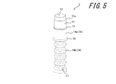
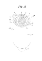
- FIG. It is a perspective view of the valve body of the medical connector shown in FIG. It is the perspective view seen from the other angle of the valve body shown in FIG.
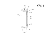
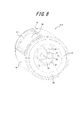
- FIG. It is a perspective view of the inner housing of the medical connector shown in FIG. It is the perspective view seen from the other angle of the inner side housing shown in FIG. It is the perspective view seen from the further another angle of the inner side housing shown in FIG.
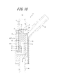
- FIG. 1 It is a longitudinal cross-sectional view of the medical connector shown in FIG. 1, and shows the state at the time of male connector insertion. It is a longitudinal cross-sectional view which shows the modification of the medical connector of FIG. It is a longitudinal cross-sectional view of the medical connector shown in FIG. 11, and shows the state at the time of male connector insertion. It is a longitudinal cross-sectional view of the medical connector which concerns on other embodiment of this invention, and shows the state at the time of male connector non-insertion. It is a longitudinal cross-sectional perspective view of the medical connector shown in FIG. It is a cross-sectional perspective view which shows the cross section along the AA of FIG. FIG. FIG. 14 is a perspective view of the inner housing of the medical connector shown in FIG. 13. It is a longitudinal cross-sectional view of the medical connector shown in FIG. 13, and shows the state at the time of male connector insertion.
- the vertical direction means a direction along the central axis of the male connector connecting portion of the medical connector
- the upper side means the direction in which the male connector is removed (that is, the upper side in FIG. 1).
- the medical connector 1 includes a housing 2 and a valve body 3.
- the housing 2 includes an outer housing 4 and an inner housing 5, and is configured by fixing the outer housing 4 to the inner housing 5.
- the outer housing 4 and the inner housing 5 are fixed to each other, for example, by welding or adhesion. Further, when the outer housing 4 and the inner housing 5 are made of synthetic resin, they may be fixed using, for example, heat welding.
- the housing 2 is constituted by two members of the outer housing 4 and the inner housing 5, but instead of this, for example, a one-membered or three-membered structure may be adopted according to the manufacturing method employed.
- a raw material of the valve body 3 it is preferable to use a rubber material, a thermoplastic elastomer, etc., for example.
- the outer housing 4 has a cylindrical male connector connecting portion 6 centering on the axis O at the upper end.
- a locking projection 7 for fixing a luer lock type male connector is formed on the upper end of the outer peripheral surface of the male connector connecting portion 6.
- the locking protrusion 7 can be omitted.
- a cylindrical outer peripheral wall portion 9 is suspended via a tapered wall portion 8 that expands in a tapered shape.
- a first medical instrument connecting portion 10 that protrudes obliquely upward is provided at the upper end portion of the outer peripheral wall portion 9.
- the valve body 3 has a columnar head 11 having an axis O as the center.
- an annular step portion 6a whose diameter is increased downward is formed on the inner peripheral surface of the male connector connection portion 6, and the head portion 11 of the valve body 3 is provided with the annular step portion.
- An intimate annular step 11a is formed.
- the head 11 is formed with a slit 12 extending straight from the central axis O in the radial direction.
- a trunk portion 14 is connected to the lower end of the head portion 11 via a shoulder portion 13 that expands in a tapered shape at the same angle as the inclination of the inner peripheral surface of the tapered wall portion 8 of the outer housing 4.
- the upper portion 14a of the barrel portion 14 is formed in a cylindrical shape centering on the axis O, and the middle portion and the lower portion in the vertical direction are formed as a bellows portion 14b.
- the hollow part 15 is formed in the trunk
- the body portion 14 is formed with a hollow portion 15 that opens to an end portion opposite to the head portion 11.
- a seal projection 16 is provided on the outer peripheral surface of the upper end portion of the bellows portion 14b as a seal portion that is in sliding contact with an accommodating recess 18 described later.
- a concave portion 17 is formed at the lower end of the bellows portion 14b.
- the concave portion 17 engages with a convex portion 22 formed in the accommodating concave portion 18 to be described later to prevent the body portion 14 from rotating in the circumferential direction.
- the hollow portion 15 configured as an internal space is liquid-tightly partitioned from a fluid flowing through a medical instrument connection portion communication path 33 described later when the body portion 14 is contracted and deformed.
- the inner housing 5 is formed with a housing recess 18 in which the body 14 of the valve body 3 is disposed.
- the housing recess 18 is defined by an inner peripheral surface of a cylindrical inner peripheral wall portion 19 centering on the axis O and an upper surface of a bottom wall portion 20 that is continuous with a lower end portion of the inner peripheral wall portion 19.
- An insertion projection 21 that protrudes upward and is inserted into the hollow portion 15 of the valve body 3 is formed at the center of the upper surface of the bottom wall portion 20.
- a convex portion 22 is formed that engages with the concave portion 17 of the valve body 3 described above and prevents the body portion 14 from rotating in the circumferential direction.
- a first air passage 23 that connects the hollow portion 15 of the valve body 3 to the space on the outer peripheral side of the inner peripheral wall portion 19 is formed.
- a second air passage 24 is formed in the inner peripheral wall portion 19 to connect a space defined by the housing recess 18 and the outer peripheral surface of the bellows portion 14 b of the valve body 3 to a space on the outer peripheral side of the inner peripheral wall portion 19. ing.
- the first ventilation path 23 and the second ventilation path 24 respectively communicate with the external space of the medical connector 1 through a gap between the inner peripheral wall portion 19 and the outer peripheral wall portion 9 of the outer housing 4.
- the inner peripheral wall part 19 is provided with a first through hole 25 at a position facing the flow path in the first medical instrument connection part 10.
- a second medical instrument connection portion 26 is formed at the lower portion of the bottom wall portion 20.
- a second through hole 27 is formed at the lower end of the inner peripheral wall portion 19 to connect the flow path in the second medical instrument connecting portion 26 to the space on the outer peripheral side of the inner peripheral wall portion 19.
- Both the first through hole 25 and the second through hole 27 are surrounded by a substantially rectangular seal protrusion 28 (see FIG. 6).
- the inside of the seal projection 28 is formed as a concave groove 29 that is recessed from the outside of the seal projection 28.
- An annular seal protrusion 30 is provided around the upper edge of the inner peripheral wall portion 19.
- the seal projections 28 and 30 are configured as separate members made of an elastic material such as rubber or thermoplastic elastomer, and may be bonded to the inner peripheral wall portion 19 or may be bonded to the inner peripheral wall portion 19 by insert molding or the like. And may be formed integrally.
- positioning protrusions 31 are formed on the inner peripheral surface of the outer peripheral wall 9 of the outer housing 4, and the positioning protrusions 31 are shown in FIG. It engages with the positioning recess 32.
- the medical connector 1 includes the housing 2 having the first medical instrument connection unit 10, the second medical instrument connection unit 26, and the male connector connection unit 6, and the male connector connection unit 6. And a valve body 3 having a head portion 11 that can be closed and a body portion 14 connected to the head portion 11.
- the medical connector 1 includes a medical instrument connection portion communication path 33 that is partitioned by the housing 2 and the valve body 3 and guides fluid from the first medical instrument connection portion 10 to the second medical instrument connection portion 26.
- the medical instrument connection portion communication path 33 is defined by the body portion 14, the first through hole 25, the concave groove portion 29, the outer peripheral wall portion 9, and the second through hole 27 of the valve body 3.
- the medical connector 1 is inserted by inserting the male connector C into the male connector connecting portion 6, and the head portion 11 of the valve body 3 is pushed in while contracting and deforming the body portion 14.
- the fluid is guided from the male connector connecting portion 6 to the medical instrument connecting portion communication passage 33 only through the gap 34 formed between the head portion 11 and the housing 2.
- the gap 34 is defined by the slit 12 and the housing 2 that are opened when the head portion 11 of the valve body 3 is pushed.
- the increase in the volume of the fluid flow path inside the housing 2, which has conventionally been a concern when the male connector C is removed, is caused by the recovery of the body 14 of the valve body 3. Since it can suppress by expansion
- the medical connector 1 the occurrence of fluid drawing in the second medical instrument connection portion 26 when the male connector C is removed from the male connector connection portion 6 is suppressed, and the fluid in the medical connector 1 is suppressed. Occurrence of stagnation can be suppressed.
- the medical connector 1 is inserted into the male connector connection portion 6 by inserting the male connector C, and the head portion 11 of the valve body 3 is pushed in while contracting and deforming the body portion 14.
- the fluid is guided from the male connector connecting portion 6 to the most upstream portion of the medical instrument connecting portion communication passage 33 only through the gap 34 formed between the housing 11 and the housing 2.
- drum 14 of the valve body 3 forms internal space (hollow part 15), and the said internal space is a medical instrument connection part communication path 33 in the case of the shrinkage deformation of the trunk
- the internal space flows through the medical instrument connecting part communication path 33 by the seal part (seal protrusion 16, see FIGS. 4 and 5) that is in sliding contact with the housing recess 18. It is separated from fluid and fluid tight.
- the body portion 14 of the valve body 3 is easily contracted and expanded, and the male connector C is inserted and removed. Can be done smoothly.
- the medical connector 1 since the medical connector 1 includes the first ventilation path 23 and the second ventilation path 24, the male connector C can be inserted and removed more smoothly. There is no need to provide the first air passage 23 and the second air passage 24.
- the housing 2 includes an accommodation recess 18 that accommodates the body portion 14 of the valve body 3, and the valve body 3 has a seal portion (seal protrusion) that is in sliding contact with the accommodation recess 18 on the outer circumferential surface of the body portion 14. 16 (see FIGS. 4 and 5), and the outer peripheral surface of the body portion 14 is a medical region having a region facing the head 11 side across the seal portion (ie, a region below the seal protrusion 16). Since the fluid flowing through the instrument connection portion communication path 33 is liquid-tightly divided, it is possible to suppress both the increase and decrease of the fluid flow path volume inside the housing 2 when the male connector C is removed.
- the medical connector 1 when the male connector C is removed from the male connector connection portion 6, not only the fluid pull-in at the second medical instrument connection portion 26 but also the fluid extrusion is suppressed. can do. That is, according to the medical connector 1, for example, when a drug is injected into a patient, it is also possible to prevent the drug corresponding to the amount of extrusion from being unintentionally injected into the patient when the male connector C is removed. can do.
- the valve body 3 is in a state where the male connector C is not inserted, and a region of 1/2 or more, more preferably 2/3 or more of the outer peripheral surface is in contact with the housing 2 or medical
- the fluid flowing through the instrument connection portion communication path 33 is partitioned liquid-tightly. More specifically, in the present embodiment, in the valve body 3, the outer surface of the head 11, the shoulder 13, and the seal protrusion 16 is in contact with the housing 2 when the male connector C is not inserted, and the body 14 A region below the seal projection 16 on the outer peripheral surface of the first and second outer peripheral surfaces is partitioned liquid-tightly from the fluid flowing through the medical instrument connecting portion communication path 33.
- the sum of the areas of the outer peripheral surface of the head 11, the shoulder 13 and the seal protrusion 16 and the area below the seal protrusion 16 on the outer peripheral surface of the trunk portion 14 is the total area of the outer peripheral surface of the valve body 3. It is 1/2 or more, more preferably 2/3 or more.
- the surface in which the valve body 3 is in contact with the fluid flowing through the medical instrument connecting portion communication path 33 in the state when the male connector C is not inserted can be made sufficiently small. Formation of the fluid retention portion can be more reliably suppressed.
- the medical connector 1 which concerns on this embodiment was set as the structure which provided the accommodation recessed part 18 which accommodates the trunk
- drum 14 of the valve body 3 is comprised so that a cylindrical shape may be made as shown in FIG. 11, and by setting it as such a structure, the inner peripheral wall part 19 and valve
- the second air passage 24 (see FIG. 1) provided in the above-described embodiment is not provided, and only the first air passage 23 can be provided.
- the outer peripheral edge portion of the cutout portion of the inner peripheral wall portion 19 and the upper end edge portion of the inner peripheral wall portion 19 may be appropriately provided with a sealing structure such as the above-described seal protrusions 28 and 30 (see FIG. 6). it can.
- Other configurations can be the same as those in the above-described embodiment.
- the medical connector 1 ′ according to the present modification having such a configuration, as in the case of the above-described embodiment, as shown in FIG. 12, by inserting the male connector C into the male connector connecting portion 6, The medical device connection portion communication path from the male connector connection portion 6 only through the gap 34 formed between the head portion 11 and the housing 2 when the head portion 11 of the valve body 3 is pushed in while contracting and deforming the body portion 14. Fluid can be directed to 33.
- the medical connector 1 ′ the increase in the fluid flow path volume inside the housing 2, which has conventionally been a concern when the male connector C is removed, is caused by the recovery of the body 14 of the valve body 3. Therefore, the occurrence of fluid drawing in the second medical instrument connection portion 26 when the male connector C is removed can be suppressed. Further, according to the medical connector 1 ′, fluid flows from the male connector connection portion 6 to the medical instrument connection portion communication path 33 only through the gap 34 between the head portion 11 and the housing 2 formed when the male connector C is inserted. Therefore, when the male connector C is not inserted, the formation of the staying portion where the fluid flowing through the medical instrument connection portion communication path 33 stays is suppressed.
- the medical connector 1 ′ is configured such that the head 11 of the valve body 3 is the body 14 by inserting the male connector C into the male connector connecting portion 6, as in the case of the above-described embodiment.
- the fluid is guided from the male connector connecting portion 6 to the most upstream portion of the medical device connecting portion communication path 33 only through the gap 34 formed between the head portion 11 and the housing 2 by being pushed in while being contracted and deformed. It has become.
- the body portion 14 of the valve body 3 forms an internal space (hollow portion 15), and the internal space is connected to the medical device connection portion communication path 33 when the body portion 14 is contracted and deformed. And fluid-tightly dividing the fluid (see FIG. 12). More specifically, in this embodiment, the internal space (hollow part 15) is liquid-tightly partitioned from the fluid flowing through the medical instrument connecting part communication path 33 by press-fitting the insertion protrusion 21 into the hollow part 15. .
- the valve body 3 is in contact with the housing 2 in a state where the male connector C is not inserted and at least 1/2 of the outer peripheral surface, more preferably 2/3 or more. More specifically, in the present modification, the valve body 3 includes an outer peripheral surface of the head portion 11, an outer peripheral surface of the shoulder portion 13, and an outer peripheral surface of the trunk portion 14 in a state where the male connector C is not inserted. Part is in contact with the housing 2. And the sum total of the area of the part which contact
- the surface in which the valve body 3 is in contact with the fluid flowing through the medical instrument connecting portion communication path 33 in the state when the male connector C is not inserted can be sufficiently reduced.
- the formation of the fluid retaining portion can be more reliably suppressed.
- the medical connector 100 according to the present embodiment differs from the embodiment described with reference to FIGS. 1 to 10 in that the configuration of the medical instrument connecting portion communication path 35 is different, and the position of the slit 12 of the valve body 3 is different.
- the structure is the same except that the positioning protrusion 31 and the positioning recess 32 between the outer housing 4 and the inner housing 5 are not provided.
- the medical instrument connection portion communication path 35 includes an annular flow path 36 that surrounds the outer peripheral surface of the body portion 14 of the valve body 3. It is out.
- the annular flow path 36 includes an annular notch 37 (see FIG. 16) formed on the upper inner peripheral surface of the inner peripheral wall portion 19 of the inner housing 5, the body portion 14 of the valve body 3, and the outer side. It is demarcated by the taper wall portion 8 of the housing 4.
- the inner peripheral wall portion 19 includes a third through hole 38 on the opposite side of the first through hole 25 across the axis O.
- the medical instrument connecting portion communication path 35 includes the third through hole 38, the cutout portion 37, the body portion 14 of the valve body 3, the tapered wall portion 8, the first through hole 25, the concave groove portion 29, It is partitioned by the outer peripheral wall portion 9 and the second through hole 27.
- the slit 12 of the valve body 3 is disposed on the opposite side across the axis O of the first through hole 25, that is, on the third through hole 38 side.
- the slit 12 can also be arrange
- a plurality of slits 12 can be arranged.
- the slit 12 is preferably arranged on the third through hole 38 side as in this example.
- the fluid flowing from the male connector C can be guided to the most upstream part of the medical instrument connecting part communication path 35, and therefore flows from the male connector C. This is because it is possible to suppress the fluid from staying in the medical instrument connection portion communication path 35.
- the head portion 11 of the valve body 3 becomes the trunk portion 14.
- the fluid can be guided from the male connector connecting portion 6 to the medical instrument connecting portion communication passage 35 only through the gap 34 formed between the head portion 11 and the housing 2 by being pushed in while being contracted and deformed.
- the housing 2 includes an accommodation recess 18 that accommodates the body portion 14 of the valve body 3, and the valve body 3 has a seal portion that is in sliding contact with the accommodation recess 18 on the outer peripheral surface of the body portion 14. In the outer peripheral surface of the body portion 14, a region facing the head 11 side across the seal portion is partitioned liquid tightly from a fluid flowing through the medical device connection portion communication path 35.
- the medical connector 100 in the second medical instrument connecting portion 26 when the male connector C is removed from the male connector connecting portion 6, as in the embodiment described with reference to FIGS. It is possible to suppress the occurrence of both fluid drawing and extrusion, and to suppress the occurrence of fluid retention in the medical connector 100.
- the body 14 of the valve body 3 forms an internal space (hollow portion 15), and the internal space is
- the body portion 14 is contracted and deformed, it is liquid-tightly partitioned from the fluid flowing through the medical instrument connecting portion communication path 35 (see FIG. 17). Therefore, according to the medical connector 100, when the male connector C is inserted into and removed from the male connector connection portion 6, the body portion 14 of the valve body 3 is easily contracted and expanded, and the male connector C is inserted and removed. Can be done smoothly.
- the valve body 3 is more than 1/2 of the outer peripheral surface when the male connector C is not inserted.
- 2/3 or more of the region is in fluid-tight partitioning with the fluid flowing through the medical device connection portion communication path 35 in contact with the housing 2. Therefore, according to the medical connector 100, in the state when the male connector C is not inserted, the surface of the valve body 3 that is in contact with the fluid flowing through the medical instrument connecting portion communication path 35 is sufficiently small. The formation of the part is more reliably suppressed.
- the medical instrument connection part communication path 35 contains the annular flow path 36 surrounding the outer peripheral surface of the trunk
- the medical connector 100 is inserted into the male connector C into the male connector connection portion 6 by the valve body 3.
- the male connector connection portion 6 and the medical device connection portion communication path 35 are passed through only the gap 34 formed between the head portion 11 and the housing 2.
- the fluid is guided to the upstream part.
Landscapes
- Health & Medical Sciences (AREA)
- Heart & Thoracic Surgery (AREA)
- Pulmonology (AREA)
- Engineering & Computer Science (AREA)
- Anesthesiology (AREA)
- Biomedical Technology (AREA)
- Hematology (AREA)
- Life Sciences & Earth Sciences (AREA)
- Animal Behavior & Ethology (AREA)
- General Health & Medical Sciences (AREA)
- Public Health (AREA)
- Veterinary Medicine (AREA)
- Infusion, Injection, And Reservoir Apparatuses (AREA)
Abstract
Connecteur médical pourvu d'un chemin de communication pour une section de connexion d'un instrument médical, le chemin étant défini par un boîtier et un corps de vanne et guidant un fluide d'une première section de connexion d'instrument médical à un seconde section de connexion d'instrument médical, le connecteur médical étant caractérisé en ce qu'un fluide est guidé dans la voie de communication pour une section de connexion d'un instrument médical à partir d'une partie de raccordement de type raccord mâle, exclusivement à travers un espace qui est formé entre une partie tête et un boîtier en raison de la déformation contractile induite dans une partie cylindrique par la partie tête de la vanne pendant l'insertion d'un connecteur mâle dans une partie de raccordement de type raccord mâle
Priority Applications (2)
| Application Number | Priority Date | Filing Date | Title |
|---|---|---|---|
| JP2017509260A JP6776225B2 (ja) | 2015-03-27 | 2016-03-22 | 医療用コネクタ |
| US15/717,353 US11116957B2 (en) | 2015-03-27 | 2017-09-27 | Medical connector |
Applications Claiming Priority (2)
| Application Number | Priority Date | Filing Date | Title |
|---|---|---|---|
| JP2015-065800 | 2015-03-27 | ||
| JP2015065800 | 2015-03-27 |
Related Child Applications (1)
| Application Number | Title | Priority Date | Filing Date |
|---|---|---|---|
| US15/717,353 Continuation US11116957B2 (en) | 2015-03-27 | 2017-09-27 | Medical connector |
Publications (1)
| Publication Number | Publication Date |
|---|---|
| WO2016157829A1 true WO2016157829A1 (fr) | 2016-10-06 |
Family
ID=57004949
Family Applications (1)
| Application Number | Title | Priority Date | Filing Date |
|---|---|---|---|
| PCT/JP2016/001646 WO2016157829A1 (fr) | 2015-03-27 | 2016-03-22 | Connecteur médical |
Country Status (3)
| Country | Link |
|---|---|
| US (1) | US11116957B2 (fr) |
| JP (1) | JP6776225B2 (fr) |
| WO (1) | WO2016157829A1 (fr) |
Cited By (1)
| Publication number | Priority date | Publication date | Assignee | Title |
|---|---|---|---|---|
| WO2022102301A1 (fr) * | 2020-11-12 | 2022-05-19 | テルモ株式会社 | Raccord à usage médical |
Families Citing this family (7)
| Publication number | Priority date | Publication date | Assignee | Title |
|---|---|---|---|---|
| WO2016157829A1 (fr) * | 2015-03-27 | 2016-10-06 | テルモ株式会社 | Connecteur médical |
| US10413663B2 (en) * | 2016-03-04 | 2019-09-17 | Zyno Medical, Llc | Automatic anti-free-flow valve for medical pumps |
| IT201600075597A1 (it) * | 2016-07-19 | 2018-01-19 | Borla Ind | Componente di flusso particolarmente per linee medicali per emodialisi |
| WO2022102300A1 (fr) * | 2020-11-12 | 2022-05-19 | テルモ株式会社 | Raccord à usage médical |
| US12036380B2 (en) * | 2021-05-04 | 2024-07-16 | Carefusion 303, Inc. | Needleless connector with compressible and deflectable valve |
| US12044342B2 (en) | 2021-12-28 | 2024-07-23 | Cytiva Us Llc | Fluid connector with slidable member |
| US12031654B2 (en) * | 2021-12-28 | 2024-07-09 | Cytiva Us Llc | Fluid connector |
Citations (7)
| Publication number | Priority date | Publication date | Assignee | Title |
|---|---|---|---|---|
| JP2001170188A (ja) * | 1999-12-17 | 2001-06-26 | Terumo Corp | コネクタ |
| US6569117B1 (en) * | 1999-01-01 | 2003-05-27 | Elcam+Plastic Cooperative Agriculture Association Ltd. | Blood sampling/injecting valve |
| US20060163515A1 (en) * | 2003-06-17 | 2006-07-27 | Ruschke Ricky R | Fluid handling device and method of making same |
| JP2008540045A (ja) * | 2005-05-16 | 2008-11-20 | ナイプロ インコーポレイテッド | ドローバック防止医療用バルブ |
| WO2009144599A1 (fr) * | 2008-04-14 | 2009-12-03 | Elcam Medical A.C.S. Ltd | Dispositif de régulation de débit activé par un embout luer |
| JP2012024565A (ja) * | 2010-06-23 | 2012-02-09 | Top Corp | コネクタ |
| WO2015145998A1 (fr) * | 2014-03-28 | 2015-10-01 | テルモ株式会社 | Raccord médical |
Family Cites Families (16)
| Publication number | Priority date | Publication date | Assignee | Title |
|---|---|---|---|---|
| US4915687A (en) * | 1989-02-17 | 1990-04-10 | Sivert George A | Needleless injection port arrangement |
| US5163922A (en) * | 1991-04-29 | 1992-11-17 | Charles E. McElveen, Jr. | Dual-valved connector for intravenous systems |
| US5839715A (en) | 1995-05-16 | 1998-11-24 | Alaris Medical Systems, Inc. | Medical adapter having needleless valve and sharpened cannula |
| US5573516A (en) * | 1995-09-18 | 1996-11-12 | Medical Connexions, Inc. | Needleless connector |
| US6228069B1 (en) * | 1999-04-05 | 2001-05-08 | Filtertek Inc. | Needleless access device |
| US7837658B2 (en) * | 2001-11-13 | 2010-11-23 | Nypro Inc. | Anti-drawback medical valve |
| US6871838B2 (en) * | 2003-04-03 | 2005-03-29 | B. Braun Medical Inc. | Injection port valve |
| US9695953B2 (en) | 2006-02-14 | 2017-07-04 | B. Braun Medical Inc. | Needleless access port valves |
| JP3166779U (ja) * | 2011-01-07 | 2011-03-24 | 秀鳳 潘 | ボールバルブを備えたシリンジアダプタ |
| US9067049B2 (en) * | 2011-07-25 | 2015-06-30 | Carefusion 303, Inc. | Providing positive displacement upon disconnection using a connector with a dual diaphragm valve |
| JP6204200B2 (ja) * | 2012-01-31 | 2017-09-27 | テルモ株式会社 | コネクタ |
| JP6316294B2 (ja) * | 2013-07-31 | 2018-04-25 | テルモ株式会社 | コネクタ及び輸液セット |
| EP3124071B1 (fr) * | 2014-03-26 | 2022-06-22 | Terumo Kabushiki Kaisha | Raccord et kit de perfusion |
| WO2016047135A1 (fr) * | 2014-09-24 | 2016-03-31 | テルモ株式会社 | Raccord medical |
| WO2016157829A1 (fr) * | 2015-03-27 | 2016-10-06 | テルモ株式会社 | Connecteur médical |
| JP6710677B2 (ja) * | 2015-03-30 | 2020-06-17 | テルモ株式会社 | 医療用コネクタ |
-
2016
- 2016-03-22 WO PCT/JP2016/001646 patent/WO2016157829A1/fr active Application Filing
- 2016-03-22 JP JP2017509260A patent/JP6776225B2/ja active Active
-
2017
- 2017-09-27 US US15/717,353 patent/US11116957B2/en active Active
Patent Citations (7)
| Publication number | Priority date | Publication date | Assignee | Title |
|---|---|---|---|---|
| US6569117B1 (en) * | 1999-01-01 | 2003-05-27 | Elcam+Plastic Cooperative Agriculture Association Ltd. | Blood sampling/injecting valve |
| JP2001170188A (ja) * | 1999-12-17 | 2001-06-26 | Terumo Corp | コネクタ |
| US20060163515A1 (en) * | 2003-06-17 | 2006-07-27 | Ruschke Ricky R | Fluid handling device and method of making same |
| JP2008540045A (ja) * | 2005-05-16 | 2008-11-20 | ナイプロ インコーポレイテッド | ドローバック防止医療用バルブ |
| WO2009144599A1 (fr) * | 2008-04-14 | 2009-12-03 | Elcam Medical A.C.S. Ltd | Dispositif de régulation de débit activé par un embout luer |
| JP2012024565A (ja) * | 2010-06-23 | 2012-02-09 | Top Corp | コネクタ |
| WO2015145998A1 (fr) * | 2014-03-28 | 2015-10-01 | テルモ株式会社 | Raccord médical |
Cited By (1)
| Publication number | Priority date | Publication date | Assignee | Title |
|---|---|---|---|---|
| WO2022102301A1 (fr) * | 2020-11-12 | 2022-05-19 | テルモ株式会社 | Raccord à usage médical |
Also Published As
| Publication number | Publication date |
|---|---|
| US20180015278A1 (en) | 2018-01-18 |
| JPWO2016157829A1 (ja) | 2018-01-18 |
| US11116957B2 (en) | 2021-09-14 |
| JP6776225B2 (ja) | 2020-10-28 |
Similar Documents
| Publication | Publication Date | Title |
|---|---|---|
| WO2016157829A1 (fr) | Connecteur médical | |
| JP7428736B2 (ja) | 支持部材を備える無針コネクタ | |
| JP6419146B2 (ja) | 蛇行流体流路付きニードルレス・コネクタ | |
| JP5952415B2 (ja) | 弁体及びこの弁体を有するコネクタ | |
| WO2016157886A1 (fr) | Raccord médical | |
| JP6403757B2 (ja) | 医療用コネクタ | |
| US9764123B2 (en) | Needle-less connector | |
| EP3199200B1 (fr) | Raccord medical | |
| JP6563903B2 (ja) | コネクタ及び輸液セット | |
| JP6321774B2 (ja) | 可撓性のバルブを備えた無針コネクタ | |
| CN101111283A (zh) | 用于医用y三通的止回阀 | |
| CN105530989A (zh) | 采用具有挠性固位臂的致动器的血液控制导管阀 | |
| WO2014162339A1 (fr) | Raccord | |
| JPWO2005120630A1 (ja) | 接続具 | |
| JP3203662U (ja) | コネクタ | |
| US20190321616A1 (en) | Medical device and method for manufacturing the same | |
| KR101833871B1 (ko) | 의료용 수액세트의 접속구 | |
| JP6670437B2 (ja) | ニードルレスコネクター | |
| JP7234003B2 (ja) | シリンジ、シリンジ組立体及びプレフィルドシリンジ | |
| JP6933386B2 (ja) | 留置針 | |
| JP6382548B2 (ja) | 医療用コネクタ | |
| JP7286495B2 (ja) | 医療用コネクタ | |
| JP6246306B2 (ja) | コネクタ | |
| JP2024516559A (ja) | 非対称の弁設計と主シール支持体とを有する逆止弁を有する無針コネクタ | |
| TWI565489B (zh) | 新式無針接取連接器及使用方法 |
Legal Events
| Date | Code | Title | Description |
|---|---|---|---|
| 121 | Ep: the epo has been informed by wipo that ep was designated in this application |
Ref document number: 16771721 Country of ref document: EP Kind code of ref document: A1 |
|
| ENP | Entry into the national phase |
Ref document number: 2017509260 Country of ref document: JP Kind code of ref document: A |
|
| NENP | Non-entry into the national phase |
Ref country code: DE |
|
| 122 | Ep: pct application non-entry in european phase |
Ref document number: 16771721 Country of ref document: EP Kind code of ref document: A1 |