WO2016157344A1 - 波面計測装置及び波面計測方法 - Google Patents
波面計測装置及び波面計測方法 Download PDFInfo
- Publication number
- WO2016157344A1 WO2016157344A1 PCT/JP2015/059806 JP2015059806W WO2016157344A1 WO 2016157344 A1 WO2016157344 A1 WO 2016157344A1 JP 2015059806 W JP2015059806 W JP 2015059806W WO 2016157344 A1 WO2016157344 A1 WO 2016157344A1
- Authority
- WO
- WIPO (PCT)
- Prior art keywords
- wavefront
- optical system
- unit
- measurement
- test optical
- Prior art date
- Legal status (The legal status is an assumption and is not a legal conclusion. Google has not performed a legal analysis and makes no representation as to the accuracy of the status listed.)
- Ceased
Links
Images












Classifications
-
- G—PHYSICS
- G01—MEASURING; TESTING
- G01M—TESTING STATIC OR DYNAMIC BALANCE OF MACHINES OR STRUCTURES; TESTING OF STRUCTURES OR APPARATUS, NOT OTHERWISE PROVIDED FOR
- G01M11/00—Testing of optical apparatus; Testing structures by optical methods not otherwise provided for
- G01M11/02—Testing optical properties
- G01M11/0207—Details of measuring devices
- G01M11/0214—Details of devices holding the object to be tested
-
- G—PHYSICS
- G01—MEASURING; TESTING
- G01M—TESTING STATIC OR DYNAMIC BALANCE OF MACHINES OR STRUCTURES; TESTING OF STRUCTURES OR APPARATUS, NOT OTHERWISE PROVIDED FOR
- G01M11/00—Testing of optical apparatus; Testing structures by optical methods not otherwise provided for
- G01M11/02—Testing optical properties
- G01M11/0242—Testing optical properties by measuring geometrical properties or aberrations
-
- G—PHYSICS
- G01—MEASURING; TESTING
- G01M—TESTING STATIC OR DYNAMIC BALANCE OF MACHINES OR STRUCTURES; TESTING OF STRUCTURES OR APPARATUS, NOT OTHERWISE PROVIDED FOR
- G01M11/00—Testing of optical apparatus; Testing structures by optical methods not otherwise provided for
- G01M11/02—Testing optical properties
- G01M11/0242—Testing optical properties by measuring geometrical properties or aberrations
- G01M11/0257—Testing optical properties by measuring geometrical properties or aberrations by analyzing the image formed by the object to be tested
Definitions
- the present invention relates to a wavefront measurement apparatus and a wavefront measurement method.
- manufacturing errors such as decentration errors and surface shape errors may occur on each lens surface. If there is a manufacturing error, the imaging performance of the optical system will be reduced.
- the off-axis wavefront aberration includes information which can not be obtained by the on-axis wavefront aberration.
- clues for analysis of the imaging performance and manufacturing error of the test optical system increase. For example, highly accurate analysis of the amount of eccentricity of the test optical system is possible.
- a wavefront aberration measuring device disclosed in Patent Document 1 as a device for measuring off-axis wavefront aberration.
- the light beam is irradiated from a position corresponding to an off-axis object point of the objective lens (lens to be measured).
- a collimated beam emerges from the objective lens, which is inclined with respect to the optical axis of the objective lens.
- the Shack-Hartmann sensor is held by a stage movable in one axial direction and a gonio stage. Then, by tilting and shifting the Shack-Hartmann sensor using the stage and the gonio stage, the direction and position of the Shack-Hartmann sensor are adjusted, and the inclined parallel luminous flux can be received by the Shack-Hartmann sensor.
- the wavefront aberration measuring device disclosed in Patent Document 1 requires a large-scale mechanism to tilt and shift the Shack-Hartmann sensor.
- the stroke for tilting is also large. It takes time for measurement.
- the present invention has been made in view of the above, and provides a wavefront measuring apparatus and a wavefront measuring method capable of measuring an off-axis transmission wavefront of a test optical system in a short time using a simple mechanism. Intended to be provided.
- the wavefront measurement device of the present invention is A light source unit, a holding unit, a light receiving optical system, a wavefront measuring unit, and a wavefront data generating unit;
- the light source unit is disposed on one side of the measurement axis
- the wavefront measuring unit is disposed on the other side of the measuring axis
- the holding unit is disposed between the light source unit and the wavefront measuring unit
- the light receiving optical system is disposed between the holding unit and the wavefront measuring unit
- the holder has an opening for holding the test optical system, Irradiating a light flux from the light source unit toward the test optical system;
- the wavefront measuring unit measures the luminous flux transmitted through the test optical system,
- a wavefront measurement apparatus that generates wavefront aberration data from a result measured by a wavefront measurement unit in a wavefront data generation unit, By the light receiving optical system, the vicinity of the opening and the vicinity of the wavefront measurement unit are optically conjugated.
- the measurement of the luminous flux is characterized by at least including measurement
- another wavefront measurement apparatus of the present invention is A light source unit, a holding unit, a light receiving optical system, a first moving mechanism, a wavefront measuring unit, and a wavefront data generating unit;
- the light source unit is disposed on one side of the measurement axis
- the wavefront measuring unit is disposed on the other side of the measuring axis
- the holding unit is disposed between the light source unit and the wavefront measuring unit
- the light receiving optical system is disposed between the holding unit and the wavefront measuring unit
- the holder has an opening for holding the test optical system, Irradiating a light flux from the light source unit toward the test optical system;
- the wavefront measuring unit measures the luminous flux transmitted through the test optical system,
- a wavefront measurement apparatus that generates wavefront aberration data from a result measured by a wavefront measurement unit in a wavefront data generation unit, By the light receiving optical system, the vicinity of the opening and the vicinity of the wavefront measurement unit are optically conjugated.
- the first moving mechanism moves the test optical system to a plurality of positions around the measurement axis,
- the transmission area of the light flux in the test optical system is different at each of a plurality of positions
- the wavefront measuring unit measures the light flux transmitted through the test optical system at each of a plurality of positions
- the wavefront data generation unit is characterized in that wavefront aberration data is generated from results of measurement at each of a plurality of positions.
- the wavefront measurement method of the present invention is An optical conjugate relationship between the vicinity of the optical system to be detected and the vicinity of the wavefront measuring unit; An eccentric drive step of decentering the test optical system with respect to the measurement axis of the wavefront measurement device;
- the wavefront measurement unit and the wavefront data generation unit may include a wavefront data acquisition step of acquiring wavefront aberration data of a light flux transmitted through the test optical system.
- the present invention it is possible to provide a wavefront measurement apparatus and a wavefront measurement method that can measure an off-axis transmission wavefront of a test optical system in a short time using a simple mechanism.
- FIG. 1 It is a figure showing a wave face measuring device of a 1st embodiment. It is a figure which shows the example of a holding
- FIG. It is a figure which shows the structure and function of SH sensor, (a) shows a mode when a plane wave injects into SH sensor, (b) is a figure showing a mode when a non-plane wave injects into SH sensor . It is a figure showing the wave face measuring device of a 2nd embodiment. It is a figure which shows the example of a 1st moving mechanism.
- FIG. 1 It is a figure which shows a mode when a lens surface is rotated, Comprising: (a) The figure in case the rotation angle is 0 degree, (b) is a figure in case a rotation angle is 30 degree, (c) is a rotation angle It is a figure at the time of 60 degrees. It is a figure which shows the position of a surface top, Comprising: (a) is a figure which shows the surface top position calculated
- the wavefront measurement apparatus includes a light source unit, a holding unit, a light receiving optical system, a wavefront measurement unit, and a wavefront data generation unit, and the light source unit is disposed on one side of the measurement axis
- the wavefront measuring unit is disposed on the other side of the measurement axis
- the holding unit is disposed between the light source unit and the wavefront measuring unit
- the light receiving optical system is disposed between the holding unit and the wavefront measuring unit
- the holding unit has an opening for holding the test optical system, and the light source unit emits a light flux toward the test optical system, and the wavefront measuring unit measures the light flux transmitted through the test optical system.
- the wavefront data generating unit generates wavefront aberration data from the result measured by the wavefront measuring unit, and the vicinity of the opening and the vicinity of the wavefront measuring unit are optically conjugated by the light receiving optical system.
- the measurement of the luminous flux at least the measurement with the center of the opening separated from the measurement axis by a predetermined distance Characterized in that it contains.
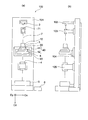
- the wavefront measurement apparatus of the first embodiment is shown in FIG. Moreover, the example of a holding
- the wavefront measuring apparatus 1 includes a light source unit 2, a holding unit 3, a light receiving optical system 4, a wavefront measuring unit 5, and a wavefront data generating unit 6.
- the light source unit 2 is disposed on one side of the measurement axis 7.
- the wavefront measuring unit 5 is disposed on the other side of the measurement axis 7.
- the holding unit 3 is disposed between the light source unit 2 and the wavefront measuring unit 5.
- the light receiving optical system 4 is disposed between the holding unit 3 and the wavefront measuring unit 5.
- the light source unit 2 is configured of an LED or a laser. A light flux L1 is emitted from the light source unit 2 toward the holding unit 3.
- the holding unit 3 is placed on the stage 8.
- stage 8 is a fixed stage.
- the holder 3 has an opening 9.
- the test optical system 10 is inserted into the opening 9.
- the test optical system 10 is a single lens.
- the single lens is inserted into the opening 9 as it is.
- the single lens may be held by the frame member and inserted into the opening 9 together with the frame member.
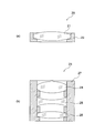
- FIG. 3 shows an example of the test optical system, where (a) is a diagram when the test optical system is composed of one single lens, and (b) is a diagram where the test optical system is composed of a plurality of lenses. It is a figure in the case of being done.
- the test optical system 20 is configured of one lens 21 and a lens frame 22.
- the test optical system 23 is configured of three single lenses 24, 25 and 26 and a lens barrel 27.
- test optical system 10 is inserted into the opening 9, and the light beam L 1 is emitted from the light source unit 2. As a result, the light beam L1 emitted from the light source unit 2 is irradiated to the test optical system 10.
- the test optical system 10 in this state is shown by a broken line.
- the light source unit 2, the test optical system 10, the light receiving optical system 4 and the wavefront measuring unit 5 are coaxial.
- the light flux L ⁇ b> 1 emitted from the light source unit 2 is irradiated to the central portion of the test optical system 10.
- the light source unit 2 When the light source unit 2 is disposed at the front focal position of the test optical system 10, a parallel light beam is emitted from the test optical system 10. When the light source unit 2 is not disposed at the front focal position of the test optical system 10, a non-parallel light beam (condensed light beam or divergent light beam) is emitted from the test optical system 10.
- the light source unit 2 may not be disposed at the front focal position of the test optical system 10, but the light source unit 2 is preferably disposed at the front focal position of the test optical system 10.
- FIG. 1 shows the case where the light source unit 2 is disposed at the front focal position of the test optical system 10. Therefore, the light flux L2 emitted from the test optical system 10 becomes a parallel light flux as indicated by a broken line.
- the axis of the test optical system 10 is separated from the measurement axis 7.
- the test optical system 10 in this state is shown by a solid line. In this state, the light source unit 2, the light receiving optical system 4 and the wavefront measuring unit 5 are coaxial, but the test optical system 10 is not coaxial with the light source unit 2, the light receiving optical system 4 and the wavefront measuring unit 5 .
- test optical system 10 In order to set such a state, only the test optical system 10 is perpendicular to the measurement axis 7 from the state where the light source unit 2, the test optical system 10, the light receiving optical system 4 and the wavefront measuring unit 5 are coaxial. It suffices to shift in the direction.
- the user may place the holding unit 3 on the stage 8 such that the center 12 of the opening 9 is separated from the measurement axis 7 by a predetermined distance. The predetermined distance may be determined according to the test optical system 10.
- the light flux incident on the test optical system 10 is a light flux in an off-axis state.
- the light beam L1 emitted from the light source unit 2 is irradiated to the peripheral portion of the test optical system 10.
- the light flux L 1 transmitted through the peripheral portion of the test optical system 10 is refracted by the test optical system 10 and then exits from the test optical system 10. Since the light source unit 2 is disposed at the front focal position of the test optical system 10, the light flux L3 emitted from the analyzing optical system 10 becomes a parallel light flux as the light flux L2.
- the traveling direction of the light flux L3 is different from the traveling direction of the light flux L2. After the light flux L3 intersects the measurement axis 7, the light flux L3 moves away from the measurement axis 7. Therefore, the light beam L3 does not enter the wavefront measuring unit 5 as it is.
- the light receiving optical system 4 is disposed between the holding unit 3 and the wavefront measuring unit 5.
- the light reception optical system 4 can direct the traveling direction of the light beam emitted from the light reception optical system 4 to the measurement axis 7 side.
- the appearance of the light beam emitted from the light receiving optical system 4 differs depending on the type of the light receiving optical system 4.
- the light receiving optical system 4 includes, for example, an optical system with an infinite focal length and an optical system with a finite focal distance.
- the former is called an afocal optical system.
- the light beam L4 emitted from the light receiving optical system 4 is a parallel light beam, and the light beam L4 is incident on the wavefront measurement unit 5 as a parallel light beam.
- the light beam L5 emitted from the light receiving optical system 4 is condensed at the focal position of the light receiving optical system 4 and then enters the wavefront measuring unit 5 while diverging.
- the opening, the light receiving optical system, and the wavefront measuring unit be positioned such that the opening is conjugate to the wavefront measuring unit.
- the vicinity of the opening 9 and the vicinity of the wavefront measuring unit 5 have an optical conjugate relationship. Therefore, the light beam L3 emitted from the test optical system 10 is always guided to the wavefront measuring unit 5.
- the light flux L 3 is refracted by the light receiving optical system 4.
- the light flux refracted by the light receiving optical system 4 is emitted from the light receiving optical system 4.
- the luminous flux L4 emitted from the light receiving optical system 4 approaches the measurement axis 7 so as to intersect the measurement axis 7.
- the position where the light beam L4 intersects the measurement axis 7 is a position optically conjugate with the vicinity of the opening 9.
- the wavefront measuring unit 5 is disposed at this position. As a result, the light beam L4 can be incident on the wavefront measuring unit 5.
- the opening, the light receiving optical system, and the wavefront measuring unit are positioned so that the back principal point of the test optical system is conjugate to the wavefront measuring unit. Is preferred.
- the light beam L4 can be more reliably made incident on the wavefront measuring unit 5. Further, the wavefront aberration shape immediately after exiting the test optical system 10 is accurately reproduced by the wavefront measuring unit.
- a wavefront shape in which a power component is added to the wavefront aberration shape immediately after exiting the test optical system 10 is reproduced by the wavefront measuring unit.
- the wavefront measuring unit 5 measures the light flux L4.
- the light flux L4 is a light flux transmitted through the test optical system 10. As described above, by the light receiving optical system 4, the vicinity of the opening 9 and the vicinity of the wavefront measuring unit 5 are in an optical conjugate relationship. Therefore, the light beam L3 can be made to enter the wavefront measuring unit 5 regardless of which direction the light beam L3 emitted from the test optical system 10 travels.
- the wavefront at the position of the wavefront measuring unit 5 and the wavefront immediately after exiting the test optical system 10 are maintained in the same shape. That is, the wavefront aberration shape immediately after exiting the test optical system 10 is reproduced to the wavefront measuring unit 5.
- the wavefront measuring unit 5 is, for example, a Shack-Hartmann sensor (hereinafter referred to as “SH sensor”).
- SH sensor Shack-Hartmann sensor
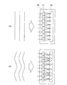
- FIG. 4 is a diagram showing the structure and function of the SH sensor, where (a) shows a plane wave incident on the SH sensor, and (b) shows a plane non-plane wave incident on the SH sensor. ing.
- the SH sensor 30 is composed of a microlens array 31 and an imaging element 32.
- the imaging device 32 is, for example, a CCD or a CMOS.
- the microlenses are arranged at equal intervals, and each microlens has no aberration.
- the microlens array 31 condenses the light flux incident on the SH sensor 30. At this time, the same number of light spot images as the number of micro lenses through which the light flux has been formed is formed at the light collecting position.
- An imaging element 32 is disposed at the light collecting position. Each of the light spot images is received by the image sensor 32.
- minute light receiving elements are two-dimensionally arranged. Therefore, the position of each light spot image can be known.
- each light spot image depends on the shape of the wavefront incident on the SH sensor 30, ie, the amount of wavefront aberration generated.
- the wavefront is divided by the microlens array 31.
- the wavefront is projected as a plurality of light spot images on the imaging surface of the imaging device 32.
- the wavefront aberration can be measured from the amount of deviation of the plurality of light spot image positions from the reference position.
- the wavefront data generation unit 6 generates wavefront aberration data from the result of measurement by the wavefront measurement unit 5. That is, wavefront aberration is measured from the amount of deviation of the plurality of light spot image positions from the reference position.
- the light flux L1 is irradiated to the outer peripheral portion of the test optical system 10. Since this irradiation position is off-axis, in this case, off-axis wavefront aberration of the test optical system 10 can be measured.
- the holding unit 3 may be placed on the stage 8 such that the center 11 of the opening 9 and the measurement axis 7 coincide with each other.
- the light beam L2 emitted from the test optical system 10 travels in parallel with the measurement axis 7 as indicated by a broken line. Since the light receiving optical system 4 is disposed between the holding unit 3 and the wavefront measuring unit 5, the light flux L 2 enters the light receiving optical system 4.
- the vicinity of the opening 9 and the vicinity of the wavefront measurement unit 5 are optically conjugated by the light receiving optical system 4. Therefore, the wavefront aberration shape immediately after exiting the test optical system 10 is reproduced to the wavefront measuring unit.
- the luminous flux L1 is irradiated to the central portion of the test optical system 10. Since this irradiation position is on axis, in this case, it is possible to measure the on-axis wavefront aberration of the test optical system 10.
- the stage 8 may be a moving stage. In this way, it is possible to easily switch between measurement of off-axis wavefront aberration and measurement of on-axis wavefront aberration simply by moving the stage 8.
- the light receiving optical system 4 is disposed between the holding unit 3 and the wavefront measuring unit 5. Therefore, the incident position of the light beam L4 in the wavefront measuring unit 5 is the same in both the measurement of the off-axis wavefront aberration and the measurement of the on-axis wavefront aberration. As a result, it is possible to measure the on-axis wavefront aberration and measure the off-axis wavefront aberration without changing the position of the wavefront measuring unit 5.
- the test optical system 10 In order to set off-axis wavefront aberration in the state of measuring on-axis wavefront aberration, it is sufficient to shift the test optical system 10 in the direction perpendicular to the measurement axis 7. In this case, the amount of movement required to shift the test optical system 10 is the same as the effective aperture of the test optical system 10. Since the amount of movement is not so large, the movement of the test optical system 10 can be completed in a short time.
- the time required to measure off-axis wavefront aberration can be very short. Therefore, measurement of off-axis wavefront aberration can be performed in a short time with a simple configuration. Moreover, measurement time can be further shortened by changing the movement amount as needed.
- the wavefront measuring apparatus includes a light source unit, a holding unit, a first moving mechanism, a light receiving optical system, a wavefront measuring unit, and a wavefront data generating unit, and the light source unit measures
- the wavefront measuring unit is disposed on one side of the axis
- the wavefront measuring unit is disposed on the other side of the measuring axis
- the holding unit is disposed between the light source unit and the wavefront measuring unit
- the light receiving optical system includes the holding unit and the wavefront
- the holding unit is disposed between the light source unit and the measurement unit.
- the holding unit has an opening that holds the test optical system.
- the light source unit emits a light flux toward the test optical system.
- the wavefront measurement unit It is a wavefront measuring device that measures the light flux that has passed through the lens and generates wavefront aberration data from the result measured by the wavefront measuring unit in the wavefront data generating unit.
- the first moving mechanism moves the test optical system to multiple positions around the measurement axis
- the transmission region of the light flux in the test optical system is different at each of the plurality of positions
- the wavefront measurement unit measures the light flux transmitted through the test optical system at each of the plurality of positions
- the wavefront data generation unit Wavefront aberration data is generated from the result of measurement at each of a plurality of positions.
- the opening, the light receiving optical system, and the wavefront measuring unit be positioned such that the opening is conjugate to the wavefront measuring unit. Furthermore, it is preferable that the opening, the light receiving optical system, and the wavefront measuring unit be positioned such that the rear principal point of the test optical system is conjugate to the wavefront measuring unit.
- the wavefront measurement apparatus of the second embodiment is shown in FIG.
- the wavefront measuring apparatus 1 ′ includes a light source unit 2, a holding unit 3, a first moving mechanism 40, a light receiving optical system 4, a wavefront measuring unit 5, and a wavefront data generating unit 6.
- the same components as those of the wavefront measuring apparatus 1 shown in FIG. 1 are assigned the same reference numerals and detailed explanations thereof will be omitted.
- the wavefront measuring apparatus 1 ′ has a first moving mechanism.
- An example of the first moving mechanism is shown in FIG.
- the first moving mechanism 40 is configured of a moving stage 41 and a moving stage 42.
- the moving stage 41 and the moving stage 42 are both moving stages in one direction.
- the moving stage 41 and the moving stage 42 are disposed such that the moving direction of the moving stage 41 and the moving direction of the moving stage 42 are orthogonal to each other.
- the test optical system 10 can be moved to various positions in the plane orthogonal to the measurement axis 7.
- the test optical system 10 can be moved to a plurality of positions around the measurement axis 7. Furthermore, the transmission region of the light flux in the test optical system 10 can be made different at each of the plurality of positions.
- the first movement mechanism rotates the test optical system to change the transmission region.
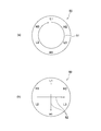
- FIG. 7 is a view showing the change of the transmission area of the light flux in the test optical system, where (a) shows the transmission area at the first position, and (b) shows the transmission area at the second position.
- FIG. 6C is a view showing the transmission area at the third position
- FIG. 7D is a view showing the transmission area at the fourth position.
- the position indicated by the broken line is the initial position of the first moving mechanism 40.
- the moving stage 41 and the moving stage 42 are each configured by a fixed unit and a moving unit. By moving the moving unit with respect to the fixed unit, it is possible to move the object placed on the moving unit. Therefore, in FIG. 7, the position indicated by the broken line indicates the fixed portion of the movable stage 41 or the fixed portion of the movable stage 42.
- the first position is a position where the test optical system 10 is moved in the right direction in the drawing from the initial position.
- the area 43 is located on the measuring axis 7.
- the luminous flux L1 passes through this area 43.
- the second position is a position where the test optical system 10 is moved upward in the plane of the drawing from the initial position.
- the area 44 is located on the measuring axis 7.
- the luminous flux L1 passes through this area 44.
- the third position is a position where the test optical system 10 is moved leftward in the drawing from the initial position.
- the area 45 is located on the measuring axis 7.
- the luminous flux L1 passes through this area 45.
- the fourth position is a position where the test optical system 10 is moved downward in the drawing from the initial position.
- the area 46 is located on the measuring axis 7.
- the luminous flux L1 passes through this area 46.
- the transmission region of the light flux in the test optical system 10 can be made different at each of the plurality of positions.
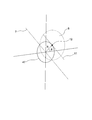
- FIG. 8 is a view showing the movement of the center of the opening.
- the opening 9 is indicated by a broken line
- the movement trajectory 47 is indicated by a solid line.
- the movement trajectory 47 shows the movement of the center 12 of the opening 9.
- the movement trajectory 47 coincides with the circumference of a circle centered on the measurement axis 7. Since the test optical system 10 is inserted into the opening 9, the test optical system 10 also moves on the circumference of a circle centered on the measurement axis 7. As described above, the test optical system 10 can be rotated along the movement trajectory 47 by using the first moving mechanism 40. Thereby, the transmission region of the light flux in the test optical system 10 is changed.
- the first moving mechanism moves the test optical system in the orbit about the measurement axis, and the wavefront measuring unit acquires wavefront aberration data while moving on the orbit. It is preferable to do.
- the movement trajectory 47 coincides with the circumference of a circle centered on the measurement axis 7. Since the movement along the circumference is a trajectory indicating revolution, the opening 9 is revolved around the measurement axis 7. Since the test optical system 10 is inserted into the opening 9, the test optical system 10 also revolves around the measurement axis 7.
- the movement track 47 indicates a revolving track, and the measurement axis 7 can be called a revolving axis.
- the test optical system 10 can be moved in a revolving orbit.
- the test optical system 10 can be stopped at a plurality of positions on the orbit of revolution. Thereby, it is possible to acquire wavefront aberration data at a plurality of positions while moving on a revolving orbit.
- the test optical system 10 is moved to a plurality of positions around the measurement axis 7. This movement can be represented by a vector. As shown in FIG. 8, the magnitude of the shift amount of the test optical system 10 is R. The magnitude R of this shift amount is the magnitude with respect to the measurement axis 7.
- the movement of the test optical system 10 is indicated by a vector with one point on the measurement axis 7 as the origin. This is called a revolution shift vector.
- a revolution shift vector is represented by (R, 0).
- the orbital shift vector is represented by (0, R).
- a revolution shift vector is represented by (R cos ⁇ , R sin ⁇ ).
- the test optical system 10 is shifted by changing this ⁇ up to 350 degrees at intervals of 10 degrees, such as 0 degrees, 10 degrees, 20 degrees, and so on.
- the movement of the test optical system 10 is called revolution, and ⁇ is called a revolution angle.
- the interval for shifting the test optical system 10 may not be 10 degrees.
- the wavefront measuring unit 5 measures the light flux transmitted through the test optical system. Then, wavefront data generation unit 6 generates wavefront aberration data from the result of measurement at each position.
- off-axis wavefront aberration measurement can be easily performed at each revolution angle at the time of revolution.
- the off-axis wavefront aberration measurement data obtained in this manner can be used to confirm the presence or absence of abnormality in the circumferential direction of the test optical system.
- the light beam may be transmitted through a half or more of the effective diameter of the test optical system by the light projection optical system. In this way, it is possible to confirm the presence or absence of an abnormality over the entire effective diameter of the test optical system in off-axis wavefront aberration measurement in revolution.
- the light receiving optical system is the front optical system located closest to the light source unit side. And at least the rear optical system located closest to the wavefront measurement unit, and it is preferable that the rear focal position of the front optical system and the front focal position of the rear optical system be matched or conjugated. .
- FIG. 13 is a diagram showing the configuration of a light receiving optical system.
- the same components as those of the wavefront measuring apparatus 1 ′ shown in FIG. 5 are assigned the same reference numerals and detailed explanations thereof will be omitted.
- the light receiving optical system can be composed of two or more optical systems, but in the wavefront measuring apparatus 60, the light receiving optical system is composed of two optical systems. That is, the light receiving optical system 61 is configured of the lens 62 and the lens 63. The lens 62 is positioned closest to the light source unit 2, and the lens 63 is positioned closer to the wavefront measuring unit 5. Thus, the lens 62 corresponds to the front optical system, and the lens 63 corresponds to the rear optical system.
- the light receiving optical system 61 is configured of the lens 62 and the lens 63, the back focal position of the lens 62 matches the front focal position of the lens 63. Therefore, the light receiving optical system 61 is an optical system with an infinite focal length.
- the light receiving optical system and the wavefront measuring unit be positioned such that the back focal position of the lens 63 coincides with the wavefront measuring unit.
- the back focal position of the lens 62 coincides with the front focal position of the lens 63, when the wavefront measurement unit 5 is made to coincide with the back focal position of the lens 63, the front focal position of the lens 62 and the wavefront measurement unit 5 And optical conjugate relationship.
- the holder and the conjugate optical system be positioned such that the opening coincides with the front focal position of the lens 62.
- test optical system 10 When the test optical system 10 is inserted into the opening 9, the test optical system 10 is located near the front focal position of the lens 62. As a result, the test optical system 10 and the wavefront measuring unit 5 substantially have an optical conjugate relationship. Therefore, the light beams L 3 and L 3 ′ emitted from the test optical system 10 are guided to the wavefront measuring unit 5.
- the test optical system and the light receiving optical system are positioned such that the back principal point of the test optical system coincides with the front focal position of the lens 62. preferable.
- test optical system 10 and the wavefront measuring unit 5 have an optical conjugate relationship. Therefore, the light beams L3 and L3 'emitted from the test optical system 10 are always guided to the wavefront measuring unit 5.
- the light beams L 3 and L 3 ′ are refracted by the lens 62 after being incident on the lens 62.
- the test optical system 9 is disposed in the vicinity of or coincident with the front focal position of the lens 62. Therefore, the light flux emitted from the lens 62 is collected at the back focal position of the lens 62. Further, the central ray of the luminous flux emitted from the lens 62 is substantially parallel to the measurement axis 7.
- the luminous flux that has passed through the back focal position of the lens 62 is made divergent and enters the lens 63.
- the back focal position of the lens 62 coincides with the front focal position of the lens 63. Therefore, the light flux incident on the lens 63 becomes parallel light flux and exits from the lens 63.
- the light beams L4 and L4 'emitted from the lens 63 approach the measurement axis 7 so as to intersect the measurement axis 7. As a result, the light beams L4 and L4 'can be incident on the wavefront measuring unit 5.
- the test optical system 10 and the wavefront measuring unit 5 are in an optical conjugate relationship by the light receiving optical system 61. Therefore, the light beams L3 and L3 'can be made to enter the wavefront measuring unit 5 regardless of the direction in which the light beams L3 and L3' emitted from the test optical system 10 travel.
- the wavefront at the position of the wavefront measuring unit 5 and the wavefront immediately after emitting the test optical system 10 are maintained in the same shape. That is, the wavefront aberration shape immediately after exiting the test optical system 10 is reproduced to the wavefront measuring unit 5.
- a relay optical system may be disposed between the lens 62 and the lens 63.
- the back focal position of the lens 62 and the front focal position of the lens 63 are in an optical conjugate relationship. In this way, it is possible to obtain the same effect as when the back focal position of the lens 62 and the front focal position of the lens 63 are matched.
- the number of microlens arrays determines the spatial resolution of the wavefront aberration shape. Therefore, as the number of microlens arrays occupied in the light flux increases, highly accurate wavefront aberration measurement becomes possible. Even when the diameter of the light beam L3 after passing through the test optical system 9 is small, a sufficient number of microlens arrays can be used by enlarging the diameter of the light beam L4 incident on the wavefront measuring unit 5 by the light receiving optical system 4. Will be able to
- the diameter of the luminous flux L4 can be twice as large as the diameter of the luminous flux L3 after passing through the test optical system 9.
- the ray angle is the angle between the ray forming the luminous flux and the measurement axis 7.
- the ray angle of the luminous flux L4 can be suppressed within the ray angle that can be measured by the SH sensor.
- the light receiving optical system 61 is a single focus optical system. Therefore, in order to change the diameter of the light beam L4 incident on the wavefront measuring unit 5, at least one of the focal length of the lens 62 and the focal length of the lens 63 may be changed. That is, at least one of the lens 62 and the lens 63 may be exchanged. By doing this, it is possible to change the diameter of the light flux L4 incident on the wavefront measuring unit 5.
- the light receiving optical system 61 may be a zoom optical system (afocal zoom). By doing this, the diameter of the light flux L4 can be freely changed without replacing the lens that constitutes the light receiving optical system 61.
- the above description has dealt with the case where an optical system with an infinite focal length is used for the light receiving optical system.
- an optical system having a finite focal length may be used as the light receiving optical system.
- the back principal point of the test optical system may be aligned with a predetermined position in the light receiving optical system, and the wavefront measurement unit of the test optical system may be aligned with the image position of the predetermined position.
- the image position of the predetermined position is a position where a real image of the object is formed when the object is arranged at the predetermined position in the light receiving optical system.
- the wavefront measurement apparatus of this embodiment has a light projection optical system between the light source unit and the holding unit.
- the projection optical system generate a collected luminous flux.
- the light projecting optical system and the holding unit be positioned such that the position of the condensing point of the condensed light beam coincides with the front focal position of the test optical system.
- FIG. 14 is a diagram showing the configuration of a light projecting optical system.
- the same components as those of the wavefront measuring apparatus 1 ′ shown in FIG. 5 are assigned the same reference numerals and detailed explanations thereof will be omitted.
- the configuration of the projection optical system shown in FIG. 14 is a configuration used when measuring a test optical system having positive refractive power.
- the light projecting optical system 71 is disposed between the light source unit 2 and the holding unit 3.
- the light projecting optical system 71 is composed of a lens 72 and a lens 73.
- the back focal position of the lens 72 matches the front focal position of the lens 73. Therefore, the projection optical system 71 is an optical system with an infinite focal length.
- the light source unit 2 is located at the front focal position of the lens 72. More specifically, the light emitting area of the light source unit 2 is located at the front focal position of the lens 72. Therefore, the divergent light beam emitted from the light source unit 2 is converted into a parallel light beam by the lens 72. The parallel luminous flux enters a lens 73 and is condensed by the lens 73.
- the test optical system 10 has positive refractive power. Therefore, the front focal point of the test optical system 10 is located above the light projecting optical system 71 in the drawing. Therefore, in the light projecting optical system 71, an image of the light emitting area of the light source unit 2 is formed on the upper side of the light projecting optical system 71. As a result, the light beams L3 and L3 'emitted from the test optical system 10 can be made into parallel light beams.
- the focal length of the lens 72 and the focal length of the lens 73 By changing the focal length of the lens 72 and the focal length of the lens 73, the position of the image of the light emitting area, the size of the image of the light emitting area, the numerical aperture at the image position of the light emitting area, and the like can be freely set. Therefore, a lens having an appropriate focal length may be used as the lens 72 and the lens 73 in accordance with the test optical system 9.
- the projection optical system 71 may be provided with an optical stop 74.
- the optical diaphragm 74 is disposed between the lens 72 and the lens 73, more specifically, at the back focal position of the lens 72.
- the position at which the optical diaphragm 74 is disposed is not limited to this position.
- the luminous flux is parallel between the lens 72 and the lens 73. Therefore, by changing the size of the opening of the optical stop 74, the diameter of the parallel light beam incident on the lens 73 can be changed. As a result, it is possible to change the numerical aperture of the collected light beam emitted from the lens 35. That is, the diameter of the light flux of the light flux L2 incident on the test optical system 9 can be changed. Therefore, an optical stop having an opening of an appropriate size may be used as the optical stop 74 in accordance with the test optical system 9.
- FIG. 15 is a diagram showing the configuration of another light projecting optical system.
- the same components as those of the wavefront measuring apparatus 1 ′ shown in FIG. 5 are assigned the same reference numerals and detailed explanations thereof will be omitted.
- the configuration of the projection optical system shown in FIG. 15 is a configuration used when measuring a test optical system having negative refractive power.
- a light projecting optical system 75 is disposed between the light source unit 2 and the holding unit 3.
- the projection optical system 75 is composed of a lens 76 and a lens 77.
- the back focal position of the lens 76 and the front focal position of the lens 77 coincide.
- the projection optical system 75 is an optical system with an infinite focal length.
- the light source unit 2 is located at the front focal position of the lens 76. More specifically, the light emitting area of the light source unit 2 is located at the front focal position of the lens 76. Therefore, the divergent light beam emitted from the light source unit 2 is converted into a parallel light beam by the lens 76. The parallel luminous flux enters a lens 77 and is condensed by the lens 77.
- the test optical system 10 ' has negative refractive power. Therefore, the front focal point of the test optical system 10 'is located below the test optical system 10' in the drawing. Therefore, in the light projecting optical system 75, an image of the light emitting area of the light source unit 2 is formed below the test optical system 10 '. As a result, the light beams L3 and L3 'emitted from the test optical system 10' can be made into parallel light beams.
- the light source unit may be matched with a predetermined position in the light projecting optical system, and the front focal position of the test optical system may be matched with the image position of the predetermined position.
- the image position of the predetermined position is a position where a real image of the object is formed when the object is arranged at the predetermined position in the light projecting optical system.
- the projection optical system can be driven in the measurement axis direction.
- the light source unit 2 is preferably moved together with the light projecting optical system 71.
- the projection optical system is preferably a zoom lens.
- the light projecting optical system be coaxial with the light receiving optical system.
- the wavefront measuring apparatus preferably includes a second moving mechanism, and the second moving mechanism preferably rotates the test optical system.
- FIG. 6 An example of the second moving mechanism is shown in FIG. About the same structure as FIG. 6, the same number is attached
- the second moving mechanism 80 is, for example, a rotary stage.
- the second moving mechanism 80 is disposed between the first moving mechanism 40 and the holding 3.
- the central axis of the rotary stage coincides with the central axis 11 of the opening 9. Therefore, the test optical system 10 can be rotated by rotating the rotation stage. Since the central axis of the rotation stage is an axis for rotating the optical system 10, it can be referred to as a rotation axis.
- the wavefront measurement apparatus of the present embodiment has a back and forth reversing mechanism, and the back and forth reversing mechanism rotates the test optical system with an axis orthogonal to the measurement axis as a rotation axis.
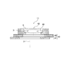
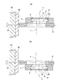
- FIG. 17 is a view showing an example of the back and forth reversing mechanism, in which (a) shows a state before reversing, and (b) shows a state after reversing.
- the same number is attached
- subjected and detailed description is abbreviate
- the front-rear reversing mechanism 90 is disposed between the main body 92 of the wavefront measuring apparatus and the stage 8.
- the back and forth reversing mechanism 90 is, for example, a rotating stage.
- the front-rear reversing mechanism 90 is a rotary stage, the front-rear reversing mechanism 90 is attached to the main body 92 such that the central axis 91 of the rotary stage is orthogonal to the measurement axis 7.
- the test optical system 10 can be inverted by rotating the rotation stage.
- the lens surface S of the test optical system is located in the upper direction in the drawing.
- a central axis 91 of the rotation stage is an axis for rotating the test optical system 10, that is, an anteroposterior inversion axis.
- the test optical system 10 is pressed against the holding unit 3 by the frame member 93.
- the holding unit 3 is fixed to the stage 8. Thereby, even if the test optical system 10 is rotated, the holder 3 and the test optical system 10 can be prevented from falling.
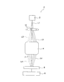
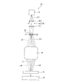
- FIG. 1 The entire configuration of the wavefront measurement apparatus of the present embodiment is shown in FIG.
- the same components as those shown in the previous figures are assigned the same reference numerals and detailed explanations thereof will be omitted.
- the wavefront measuring apparatus 100 has a main body unit 101.
- the main body unit 101 includes a light source unit 2, a light projecting optical system 71, a holding unit 3, a light receiving optical system 4, a wavefront measuring unit 5, and a wavefront data generating unit 6.
- the light source unit 2 is attached to the main body unit 101 via the holding member 102.
- the light projecting optical system 71 is attached to the main body portion 101 via the holding member 103.
- the light receiving optical system 4 is attached to the main body portion 101 via the holding member 105.
- the holder 3 is attached to the second moving mechanism 80.
- the second moving mechanism 80 is attached to the first moving mechanism 40.
- the first moving mechanism 40 is attached to the stage 8.
- the stage 8 is attached to the back and forth reversing mechanism 90.
- the back and forth reversing mechanism 90 is attached to the main body portion 101 via the holding member 104.
- the wavefront measuring apparatus 100 can measure an optical system under test having various focal lengths. Even if the test optical system to be measured changes, if the light receiving optical system 4 is not replaced, the position conjugate with the wavefront measuring unit 5 does not change. On the other hand, the position of the rear principal point of the test optical system 10 changes each time the test optical system to be measured changes.
- the back principal point of the test optical system 10 and the wavefront measuring unit 5 have an optical conjugate relationship. Therefore, it is preferable that the holding member 104 be provided with a moving mechanism.
- the rear principal point of the test optical system 10 and the wavefront measuring unit 5 can be brought into an optical conjugate relationship.
- the light receiving optical system 4 is configured of a lens 62 and a lens 63.
- the test optical system 10 is moved to match the rear focal point position of the test optical system 10 with the front focal position of the lens 62.
- test optical system 10 When an optical system having a finite focal length is used for the light receiving optical system 4, the test optical system 10 is moved to position the rear principal point of the test optical system 10 at a position conjugate with the wavefront measurement unit 5. Match.
- both the holding members 102 and 103 have a moving mechanism.
- the light projecting optical system 71 is configured by the lens 72 and the lens 73.
- the holding light source unit 2 and the light projecting optical system 71 are moved to match the back focal position of the lens 73 with the front focal position of the test optical system 10.
- the holding light source unit 2 and the projection optical system 71 are moved to the front focal position of the test optical system 10. Make the focusing points formed by
- the projection optical system 71 is formed at the front focal position of the test optical system 10 simply by moving the projection optical system 71. In some cases, it is possible to make the focusing points coincide.
- the light source unit 2 is held by the holding member 102, and the light projecting optical system 71 is held by the holding member 103. However, the light source unit 2 and the light projecting optical system 71 are held by the same holding member. It may have a mechanism.
- the projection optical system 71 can be replaced with another projection optical system. Also, the projection optical system 71 can be a zoom lens. Also in this case, the focal point generated by the light projecting optical system 71 may not coincide with the front focal position of the test optical system 10. Therefore, as described above, it is sufficient to adjust the positions of the light source unit and the projection optical system so that the focal point generated by the projection optical system 71 matches the front focal position of the test optical system 10 .
- the light receiving optical system 4 can be replaced with another light receiving optical system. Further, the light receiving optical system 4 can be a zoom lens. Also in this case, the position conjugate with the wavefront measurement unit 5 may change. Also in this case, as described above, the test optical system 10 may be moved. Also, the light receiving optical system 4 and the wavefront measuring unit 5 may be moved as needed. By doing this, the back principal point of the test optical system 10 and the wavefront measuring unit 5 can be brought into an optical conjugate relationship.
- the wavefront measurement method of the present embodiment will be described.
- the test optical system Prior to performing the wavefront measurement, the test optical system is set in the wavefront measuring apparatus. At this time, the test optical system is set in the wavefront measurement apparatus such that the vicinity of the test optical system and the vicinity of the wavefront measurement unit have an optical conjugate relationship. Further, the test optical system is set in the wavefront measurement apparatus so that the test optical system is decentered with respect to the measurement axis of the wavefront measurement apparatus.
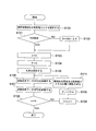
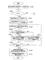
- FIG. 19 is a flowchart of the wavefront measurement method of the first embodiment.
- the test optical system is moved to a plurality of positions around the measurement axis, and the transmission region of the light flux in the test optical system is made to have a plurality of positions. . Therefore, in the wavefront measurement method of the first embodiment, the number of times of measurement is set in step S100. In setting the number of measurements, the number of measurements may be specified, but the angle increment ⁇ may be specified. The angle increment ⁇ is a variation of the angle when the test optical system 10 is shifted, such as 0 degree, 10 degrees, 20 degrees, and so on.
- step S101 confirmation of setting contents is performed.
- the angle increment ⁇ is set, the number of measurements is obtained from the angle increment ⁇ in step S102.
- step S103 the parameter n indicating the number of measurements is initialized, and in step S104, the parameter ⁇ indicating the revolution angle is initialized. Then, step S105 is executed. In step S105, the light beam is irradiated to the test optical system.
- wavefront aberration data WFD is acquired using the light beam transmitted through the test optical system.
- the acquired wavefront aberration data WFD is stored. This completes the first measurement.
- step S108 the number of measurements is confirmed. If the number of measurements does not match the set number, one is added at step S109. In addition, ⁇ is added in step S110, and a new revolution angle ⁇ is set.
- step S111 movement of the test optical system is performed based on the newly set revolution angle ⁇ .
- the new position of the test optical system is a position corresponding to the revolution angle ⁇ . Then, acquisition and storage of wavefront aberration data WFD at a new position are performed.
- Steps S106 to S111 are repeated until the number of times of measurement matches the set number of times. If the number of measurements matches the set number, the measurement is terminated.
- the wavefront aberration data WFD at each rotation angle in the state before rotating the test optical system that is, in the state in which the test optical system is first set in the wavefront measuring apparatus.
- spot groups light spot images (hereinafter referred to as “spot groups”) of the same number as the number of microlenses are formed. By imaging this spot group with an imaging device, position data is acquired for each spot of the spot group.
- ⁇ is 10 degrees, 36 pieces of wavefront aberration data WFD are obtained. It should be noted that there is no problem even if there is some misalignment between the measurement axis and the revolution axis.
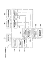
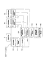
- the wavefront data generation unit 6 includes an arithmetic processing unit 110, a program storage unit 111, a data storage unit 112, and a first moving mechanism control unit 113.
- the second moving mechanism control unit 114 will be described in the wavefront measurement method of the second embodiment.
- the arithmetic processing unit 110 performs various operations and processing in accordance with a designated program.
- the program storage unit 111 stores a program for causing the arithmetic processing unit 110 to execute predetermined processing.
- the program storage unit 111 stores, for example, a program for executing the process of the flowchart shown in FIG. This program can also be read from the outside of the wavefront data generation unit 6. Therefore, the program storage unit 111 can be omitted.
- the data storage unit 112 stores the wavefront aberration data WFD acquired by the wavefront measurement unit 5 and the result of the processing performed by the arithmetic processing unit 110.
- the first moving mechanism control unit 113 controls the first moving mechanism 40 based on an instruction from the arithmetic processing unit 110.
- the first movement mechanism 40 moves the test optical system to a position corresponding to the revolution angle ⁇ .
- the second moving mechanism control unit 114 and the second moving mechanism 80 are illustrated.
- the movement of the test optical system is only revolution. Therefore, in order to move the test optical system, it is sufficient if the first moving mechanism control unit 113 and the first moving mechanism 40 are provided, and the second moving mechanism control unit 114 and the second moving mechanism 80 is unnecessary.
- the wavefront measurement method of the second embodiment is a method of measuring off-axis wavefront aberration by revolving the test optical system and rotating it.
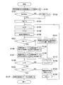
- FIG. 21 is a flowchart of the wavefront measurement method of the second embodiment. The same processes as those in the flowchart of the wavefront measurement method of the first embodiment are denoted by the same reference numerals, and detailed description thereof is omitted.
- the test optical system is rotated to “off-axis wavefront aberration measurement by revolution”.
- the state before rotating the test optical system is referred to as a first state
- the state after rotating the test optical system is referred to as a second state.
- the parameter FG is used to distinguish between the first state and the second state.
- a parameter FG indicating a rotation state is initialized.
- the state in which the test optical system is set in the wavefront measurement apparatus is the first state.
- step S121 confirmation of the autorotation state is performed.
- steps S106 to S111 are repeated until the number of measurements matches the set number. If the number of times of measurement matches the set number of times, the measurement in the first state is ended.
- step S122 confirmation of the rotation state is performed.
- step S123 is executed.
- step S123 rotation of the test optical system is performed.
- the rotation angle is preferably 180 degrees.
- step S124 1 is set to the parameter FG to indicate the second state. Then, the process returns to step S103.
- step S125 wavefront aberration data WFD 'is acquired using the light beam transmitted through the test optical system.
- step S126 storage of the acquired wavefront aberration data WFD 'is performed. Acquisition and storage of wavefront wavefront aberration data WFD 'are repeated until the fixed number of times coincides with the set number of times.
- step S127 wavefront aberration change data is acquired.
- wavefront aberration data acquired in the first state is used as reference wavefront data
- wavefront aberration data acquired in the second state is used as measurement wavefront data
- wavefront aberration change data associated with rotation is acquired.
- test optical system is rotated 180 degrees in the measurement method of the second embodiment
- present invention is not limited to this value. There is no problem even if there is some misalignment between the measurement axis and the rotation axis. There is no problem even if there is some misalignment between the axis of the test optical system and the rotation axis.
- the wavefront aberration data WFD ' is obtained at each rotation angle in the state after the rotation.
- a Shack-Hartmann sensor is used as the wavefront measurement unit, position data is acquired for each spot of the spot group.
- ⁇ is 10 degrees, 36 pieces of wavefront aberration data WFD 'can be obtained even in a state after rotating the test optical system. It should be noted that there is no problem even if there is some misalignment between the measurement axis and the revolution axis.
- the wavefront aberration change data is analyzed with the wavefront aberration data WFD before rotation of the test optical system as reference wavefront aberration data and the wavefront aberration data WFD 'after rotation as measurement wavefront aberration data.
- the wavefront aberration change data is analyzed at each of a plurality of positions at which the wavefront aberration data WFD and WFD 'are acquired. As a result, 36 wavefront aberration change data are obtained.
- the wavefront measurement apparatus of the present embodiment includes the pre-rotation wavefront data acquisition control unit, the post-rotation wavefront data acquisition control unit, and the wavefront change data analysis unit.
- the first state is the state before the rotation by the second moving mechanism is performed
- the second state is the state after the rotation by the second moving mechanism is performed
- the wavefront data before rotation is
- the acquisition control unit moves the test optical system with respect to the measurement axis in the orbital path, stores wavefront aberration data acquired at each of a plurality of positions in the orbital path, and rotates the wavefront data after rotation
- the acquisition control unit moves the test optical system with respect to the measurement axis in the orbital path, stores wavefront aberration data acquired at each of a plurality of positions in the orbital path, and analyzes the wavefront change data
- the unit references the wavefront aberration data acquired in the first state. And over data, wavefront aberration data obtained in the second state the measured wavefront data, it is prefer
- FIG. 20 A processing unit including a wavefront data generation unit is shown in FIG.
- the same components as in FIG. 20 are assigned the same reference numerals and detailed explanations thereof will be omitted.
- the wavefront data generation unit 6A includes an arithmetic processing unit 110, a program storage unit 111, a data storage unit 112, a first wavefront data acquisition control unit 121, a second wavefront data acquisition control unit 122, and a first.
- the movement mechanism control unit 113 and the second movement mechanism control unit 114 are included.
- a wavefront change data analysis unit 130 is connected to the wavefront data generation unit 6A.
- the first wavefront data acquisition control unit 121 is a pre-rotation wavefront data acquisition control unit.
- the first wavefront data acquisition control unit 121 executes processing based on the first program.
- the processing in the first program in the first state, that is, in a state before the test optical system is rotated, the test optical system is moved in the orbit about the measurement axis, and at a plurality of positions in the orbit This is processing for acquiring and storing wavefront aberration data WFD.
- the first moving mechanism control unit 113 and the second moving mechanism control unit 114 are controlled by the first moving mechanism 40 and the second moving mechanism 80 based on an instruction from the first wavefront data acquisition control unit 121. Control.
- the second wavefront data acquisition control unit 122 is an after-rotation wavefront data acquisition control unit.
- the second wavefront data acquisition control unit 122 executes the process based on the second program.
- the second program in the second state, that is, in a state after rotating the test optical system, the test optical system is moved in the orbital path with respect to the measurement axis, and a plurality of positions of the orbital path are moved. Is processing for acquiring and storing wavefront aberration data WFD ′.
- the first movement mechanism control unit 113 and the second movement mechanism control unit 114 perform the first movement mechanism 40 and the second movement mechanism 80. Control.
- the load on the arithmetic processing unit 110 can be reduced, and the processing speed can also be improved.
- the processing of the second wavefront data acquisition control unit 122 may be performed by the first wavefront data acquisition control unit 121.
- the processing in the first wavefront data acquisition control unit 121 and the processing in the second wavefront data acquisition control unit 122 may be performed by the arithmetic processing unit 110.
- the wavefront data generation unit 6 shown in FIG. 20 can be used in place of the wavefront data generation unit 6A.
- the wavefront measurement method of the third embodiment is a method of performing Zernike fitting.
- FIG. 23 is a flowchart of the wavefront measurement method of the third embodiment. In FIG. 23, illustration of many of the processes in the flowchart of the wavefront measurement method according to the second embodiment is omitted.
- step S127 wavefront aberration change data associated with rotation is acquired.
- step S128 Zernike fitting is performed on the wavefront aberration change data.
- position data is acquired for each spot of the spot group.
- the position of each spot of the spot group of the reference wavefront aberration data and the position of each spot of the spot group of the measured wavefront aberration data are acquired.
- the amount of change in the position of each spot of the spot group of the measured wavefront aberration data is fitted to the differential function of the Zernike polynomial. This gives the Zernike coefficients.
- the obtained Zernike coefficients are called Zernike wavefront aberration change data. In this way, the amount of aberration can be quantified.
- the reference wavefront aberration data and the measured wavefront aberration data are data of the same test optical system. Therefore, the process of using the reference wavefront aberration data can be said to be performing self-reference.
- the wavefront change data analysis unit performs Zernike fitting on wavefront aberration change data acquired at each of a plurality of positions, It is preferable to acquire Zernike wavefront aberration change data at each of the three positions.
- the wavefront measurement method of the third embodiment is performed by the wavefront change data analysis unit 130 shown in FIG.
- the processing in the wavefront change data analysis unit 130 may be performed by the arithmetic processing unit 110.
- the processing performed by the processing unit illustrated in FIG. 22 can be performed by the wavefront data generation unit 6 illustrated in FIG.
- the wavefront measurement method of the fourth embodiment is a method performed subsequently to the wavefront measurement method of the third embodiment.
- FIG. 24 is a flowchart of the wavefront measurement method of the fourth embodiment. The same processes as in FIG. 23 will be assigned the same reference numerals and detailed explanations thereof will be omitted.
- the measurement method of the third embodiment is the “self reference method”
- sum operation and difference operation are performed using Zernike wavefront aberration change data obtained by the self reference method.
- step S130 a pair of acquisition positions facing each other across the measurement axis is extracted.
- the positions of the extracted pairs are 180 degrees symmetrical around the measurement axis because they are opposed to each other across the measurement axis.
- step S131 is executed.
- step S131 the order of pupil coordinates of the Zernike polynomial is confirmed for the extracted Zernike wavefront aberration change data of the pair. If the order of the pupil coordinates of the Zernike polynomial is an even order, step S132 is executed. If the order of the pupil coordinates of the Zernike polynomial is an odd order, step S133 is executed.
- step S132 a difference operation is performed on Zernike coefficients of even-order pupil coordinates of the Zernike polynomial among the Zernike wavefront aberration change data.
- step S133 a sum operation is performed on Zernike coefficients of which the pupil coordinates of the Zernike polynomial are odd-order among the Zernike wavefront aberration change data.
- step S134 the number of pairs for which this process has ended is confirmed.
- the aberration component can be considered as an aberration component amount generated in proportion to the first power of the eccentricity amount or displacement amount of the test optical system.
- the aberration component can also be obtained as follows.
- the wavefront aberration caused by the first power of the eccentricity of the test optical system is shown as a function of the object height coordinate.
- the object height coordinate can be considered to correspond to the shift vector of the test optical system. Therefore, an aberration component can be obtained by applying Zernike wavefront aberration data to this function using an algorithm such as the least squares method.
- the wavefront measurement apparatus of the present embodiment has an aberration component amount extraction and analysis unit, and the aberration component amount extraction and analysis unit determines the Zernike wavefront aberration obtained in each state.
- the pupil coordinates of the Zernike polynomial take differences with respect to the even-order Zernike coefficients among the Zernike wavefront aberration change data symmetrical about the measurement axis by 180 degrees, and the pupil coordinates of the Zernike polynomial sum over the odd-order Zernike coefficients
- the aberration component is extracted.
- FIG. 22 Another processing unit including a wavefront data generation unit is shown in FIG.
- the same components as in FIG. 22 will be assigned the same reference numerals and detailed explanations thereof will be omitted.
- An aberration component amount extraction analysis unit 140 is connected to the wavefront data generation unit 6A.
- the aberration component amount extraction and analysis unit 140 performs the processing from step S130 to step S134 described above. Thereby, an aberration component is obtained.
- the processing in the aberration component amount extraction analysis unit 140 may be performed in the arithmetic processing unit 110.
- the processing performed by the processing unit illustrated in FIG. 25 can be performed by the wavefront data generation unit 6 illustrated in FIG.
- the wavefront measurement method of the fifth embodiment is a method performed subsequently to the wavefront measurement method of the fourth embodiment.
- FIG. 26 is a flowchart of the wavefront measurement method of the fourth embodiment. The same processes as in FIG. 24 will be assigned the same reference numerals and detailed descriptions thereof will be omitted.
- the measurement method of the fourth embodiment is “first-order eccentric aberration extraction method”
- an aberration component obtained by the first-order eccentric aberration extraction method is used to be subjected to rotation axis reference Calculate the eccentricity of the optical system.
- the rotation axis reference eccentricity calculation unit carries out step S140.
- the eccentric aberration sensitivity is calculated in advance before the execution of step S140.
- Eccentric aberration sensitivity is calculated using optical CAD or the like.
- the decentration aberration sensitivity is calculated as follows in order to obtain an amount represented by a component of the first power of the amount of decentration.
- the wavefront aberration change data for the design shape of the test optical system is calculated.
- the wavefront aberration change data indicates the wavefront aberration shape change of the transmitted wavefront aberration when the target surface is decentered by the unit eccentricity amount.
- Zernike fitting of wavefront aberration change data is performed to obtain Zernike coefficients, that is, Zernike wavefront aberration change data.
- Zernike wavefront aberration change data is obtained in two states of a 180 ° symmetrical revolution angle.
- the pupil coordinates of the Zernike polynomial take the difference for the Zernike coefficients of the even term, and the pupil coordinates of the Zernike polynomial take the sum of the Zernike coefficients of the odd term.
- the result obtained by this calculation is taken as the decentration aberration sensitivity.
- the decentration aberration sensitivity can be considered as a unit decentering amount for each degree of freedom of decentration on each surface of the test optical system, or an aberration component amount generated in proportion to the first power of the unit displacement amount.
- step S140 simultaneous linear equations are established for the decentration aberration sensitivity, the aberration component, and the displacement amount of each decentering degree of freedom of each surface of the test optical system accompanying rotation. Then, the simultaneous linear equations are analyzed by an algorithm such as the least squares method. In this way, the amount of displacement for each degree of eccentricity on each surface of the test optical system involved in rotation is calculated.
- the wavefront measurement apparatus of the present embodiment has a rotation axis reference eccentricity calculation unit, and the rotation axis reference eccentricity calculation unit analyzes the analyzed optical system. It is preferable to calculate the amount of eccentricity of the test optical system based on the rotation axis from the amount of displacement of each degree of eccentricity of each surface.
- FIG. 25 Another processing unit including a wavefront data generation unit is shown in FIG.
- the same components as in FIG. 25 will be assigned the same reference numerals and detailed explanations thereof will be omitted.
- the rotation axis reference eccentricity calculation unit 150 is connected to the wavefront data generation unit 6A.
- the rotation axis reference eccentricity amount calculation unit 150 performs the processing of step S140 and step S141 described above. As a result, the amount of eccentricity of the test optical system based on the rotation axis can be obtained.
- the processing of the rotation axis reference eccentricity calculation unit 150 may be performed by the arithmetic processing unit 110.
- the processing performed by the processing unit shown in FIG. 27 can be performed by the wavefront data generation unit 6 shown in FIG.
- the displacement amount of each eccentric degree of freedom can be specified as a spatial position by providing a reference position by considering the rotation angle. Specifically, when the rotation angle is 180 degrees, the displacement amount of each eccentric degree of freedom on each surface of the test optical system accompanying rotation is divided by -2, the position of the lens surface before rotation on the rotation axis basis Can be identified.
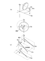
- FIG. 28 is a diagram showing the amount of movement of the ball center due to the rotation of the test optical system.
- the test optical system 10 is composed of four lens surfaces.
- the ball center 200, the ball center 201, the ball center 202, and the ball center 203 are located on one side of the rotation axis.
- the ball center 200, the ball center 201, the ball center 202, and the ball center 203 move to the other side of the rotation axis.
- the other side is a position opposite to the one side with respect to the rotation axis.
- the eccentricity of the ball center with respect to the rotation axis is ⁇ 1 for the ball center 200, ⁇ 2 for the ball center 201, ⁇ 3 for the ball center 202, and ⁇ 4 for the ball center 203.
- the rotation of the test optical system 10 displaces each of the ball center 200, the ball center 201, the ball center 202, and the ball center 203. This displacement amount is ⁇ 2 times the eccentricity amount with respect to the rotation axis before rotation.
- the amount of decentration between the lens surfaces may be evaluated.
- a new axis 210 is set such that the amount of eccentricity of the plurality of lens surfaces distributed in space is minimized. Then, the decentering amount of the lens surface may be evaluated with reference to the new axis 210.
- the setting of the new axis 210 is, for example, setting a temporary axis, and taking the sum of squares on all lens surfaces with respect to the distance from the temporary axis to the ball center. Then, the temporary axis may be changed, and the temporary axis when the sum of squares becomes the minimum may be set as a new axis. Alternatively, the sum of squares is calculated on all lens surfaces with respect to an amount obtained by dividing the distance from the tentative axis to the spherical center by the radius of curvature of the lens. Then, the temporary axis may be changed, and the temporary axis when the sum of squares becomes minimum may be set as a new axis.
- an original axis can be defined in space, and the amount of decentration can be calculated as the position of the lens surface based on that axis.
- the aspheric surface inclination of the second surface with respect to the aspheric surface of the first surface can be calculated, and the aspheric surface top position of the second surface can be calculated.
- the wavefront aberration data is measured while moving the test optical system along the orbital path. By this movement, acquisition of wavefront aberration data is performed circumferentially with respect to the test optical system. Therefore, according to the wavefront measurement apparatus and the wavefront measurement method of the present embodiment, for example, even if there is a surface accuracy error in the test optical system, it is possible to perform robust eccentricity measurement.
- the curvature radius error of the surface and the rotationally symmetric waviness shapes such as the 4th, 9th, 16th, and so on of the Zernike terms shown in Table 1
- the self-reference method can be canceled by the method of rotating the test optical system
- it can not be canceled by the self-reference method of 180 degree rotation for the shape of the three-leaf surface accuracy error (10, 11, ).
- the surface accuracy error of the three-leaf shape may change the amount of eccentricity depending on the orientation of the test optical system in this method, even if the eccentricity is measured by measuring the sectional shape.
- very robust eccentricity measurement can be performed regardless of the orientation of the test optical system.
- the wavefront measuring apparatus 1 ′ can obtain the surface top position of the test optical system 10 by analyzing the wavefront aberration data. Therefore, the case where the surface apex position is determined by measuring the test optical system with two patterns will be described.
- FIG. 9 is a view showing the surface shape of the test optical system.
- the test optical system 10 is a single lens.
- the lens surface 50 has a plurality of concave and convex portions at the periphery of the lens. Specifically, as shown in FIG. 9, the recess L1 and the protrusion H1, the recess L2 and the protrusion H2, and the recess L3 and the protrusion H3 are provided. The recess and the protrusion are opposed to each other across the center of the surface.
- the surface shape shown in FIG. 9 is a shape generated due to a manufacturing error, and is not a shape determined by design.
- the case where measurement is performed multiple times using the same test optical system 10 will be considered.
- the shape of the lens surface and the eccentric position are not known before the measurement. Therefore, when the measurement apparatus is provided with the reference position and the test optical system 10 is set in the measurement apparatus, for example, the following situation occurs.
- the test optical system 10 is set such that the recess L1 coincides with the reference position.
- the test optical system 10 is set such that the convex portion H2 matches the reference position.
- the test optical system 10 is set such that the intermediate position between the convex portion H3 and the concave portion L2 coincides with the reference position.
- the specific part in the test optical system 10 is, for example, a concave part, a convex part, and a surface top position (eccentric position).
- FIG. 10 shows a measurement pattern, where (a) shows a first pattern and (b) shows a second pattern.
- the first pattern 51 In the measurement according to the first pattern 51, as shown in FIG. 10A, the light beam irradiated to the peripheral portion of the lens surface 50 is moved in a circle.
- the first pattern 51 is the same as the pattern when the position of the luminous flux is fixed and the test optical system is revolved. Therefore, the first pattern 51 can be said to be a measurement pattern in the wavefront measurement device of the present embodiment.
- the light beam irradiated to the lens surface 50 is moved in the cross direction.
- the second pattern 52 is one of the measurement patterns frequently used in the conventional measuring device.
- the luminous flux is measured at a plurality of positions while moving the luminous flux. Then, using the measured data at each measured position, the surface top position is calculated. Therefore, in the measurement according to the first pattern 51, the surface top position is calculated when the movement of drawing the circle is completed. Further, in the second pattern 52 measurement, the surface top position is calculated when the movement for drawing a cross is completed.
- the situation in which the direction of the test optical system 10 with respect to the reference position is different each time the test optical system 10 is mounted on the measurement apparatus can be reproduced by rotating the lens surface 50.
- FIG. 11 is a view showing a state in which the lens surface is rotated, and (a) a view when the rotation angle is 0 degree, (b) a view when the rotation angle is 30 degree, (c) Is a diagram when the rotation angle is 60 degrees.
- the reference position 53 is a reference position of the measuring device.
- the lens surface 50 is set such that the recess L1 coincides with the reference position 53.
- measurement according to the first pattern 51 is performed to calculate the surface top position.
- measurement is performed with the second pattern 52 in the same state to calculate the surface top position.
- the lens surface is rotated 30 degrees, and a second measurement is performed.
- the lens surface 50 is set such that the intermediate position between the concave portion L1 and the convex portion H2 coincides with the reference position 53.
- measurement according to the first pattern 51 is performed to calculate the surface top position.
- measurement is performed with the second pattern 52 in the same state to calculate the surface top position.
- the lens surface is further rotated by 30 degrees, and the third measurement is performed.
- the lens surface 50 is set such that the convex portion H2 coincides with the reference position 53.
- measurement according to the first pattern 51 is performed to calculate the surface top position.
- measurement is performed with the second pattern 52 in the same state to calculate the surface top position.
- FIG. 12 shows the position of the top of the surface, where (a) shows the position of the top of the surface determined from the measurement according to the first pattern, and (b) shows the position of the top of the surface determined from the measurement according to the second pattern.
- the origin represents the rotation axis
- the XY axes are two orthogonal axes orthogonal to the rotation axis, and indicate the direction and the magnitude of the amount of eccentricity.
- FIG. 12 shows the measurement results when the lens surface is rotated every 20 degrees.
- the number of measurements is 18, the number of surface top positions obtained by the measurement is also 18.
- each point of the surface top position SP1 of the first surface is connected by a solid line.
- the points of the second surface top position SP2 are connected by broken lines.
- the first surface top position SP1 is located inside the second surface top position SP2 at any angle. Therefore, when measuring in the first pattern, the surface top position can be correctly obtained even if the orientation of the test optical system 10 with respect to the reference position is different. That is, regardless of the orientation of the test optical system 10 in the measurement apparatus, the surface top position can be correctly obtained.
- the first surface top position SP1 may also be located inside the second surface top position SP2. If so, the first surface top position SP1 may be located outside the second surface top position SP2. Therefore, in the case of measurement in the second pattern, when the direction of the test optical system 10 with respect to the reference position is different, it means that the surface top position varies. That is, it means that the surface top position varies depending on the direction when the test optical system 10 is set in the measurement device.
- the wavefront aberration, the amount of eccentricity, and the position of the top of the surface can be correctly determined regardless of the orientation of the test optical system 10 in the measuring apparatus. Can.
- simultaneous linear equations are established for the decentering aberration sensitivity, the aberration component, and the amount of displacement of each decentering degree of freedom on each surface of the test optical system accompanying rotation. Then, simultaneous linear equations are analyzed by an algorithm such as the least squares method. As a result, it is possible to calculate the amount of displacement of each eccentric degree of freedom on each surface of the test optical system accompanying rotation. When this calculation is performed, it can be considered that the fitting residual reflects the degree of manufacturing error other than the decentering of the test optical system. Therefore, this information can also be used as a clue to the performance of the test optical system and the manufacturing error analysis.
- the wavefront measurement method of the present embodiment it is preferable to perform wavefront measurement using the above-described front-rear reversing mechanism 90. According to the wavefront measurement method of the present embodiment, it is possible to measure the eccentricity for each degree of eccentricity, even when the degree of eccentricity is large. Alternatively, the eccentricity measurement accuracy can be improved.
- the holding unit 3 is located on the second moving mechanism 80. Further, the second moving mechanism 80 is located on the first moving mechanism 40. Therefore, the holding unit 3 is configured to be able to perform off-axis shift for every rotation mechanism (second movement mechanism) that rotates the test optical system by 10 rotations. In the wavefront measuring apparatus 100, while performing revolution measurement by off-axis shift and performing off-axis shift, it is possible to implement the self-reference method by autorotation of the test optical system.
- a feature of the wavefront measurement method of the present embodiment is that it has a step of rotating the holding unit 3 180 degrees around an axis perpendicular to the measurement axis 7.
- the rotation axis is the front and rear reverse shaft 91.
- the front and rear reverse axis 91 is parallel to the Y axis in the wavefront measurement apparatus.
- off-axis wavefront aberration measurement by revolution a self-reference method, and a first-order eccentric aberration extraction method are performed in a state before rotating the holding unit around the longitudinal inversion axis 91.
- the holding unit 3 is rotated 180 degrees around the front and rear reversing shaft 91.
- the holding unit 3 is rotated 180 degrees around the longitudinal inversion shaft 91, the front and back of the test optical system 10 are inverted around the Y axis.
- the measuring axis 7 and the rotation axis (for example, the central axis 11 of the opening 9) may have some misalignment.
- the relative positional relationship between the rotation axis and the test optical system 10 does not change.
- FIG. 29 is a diagram for explaining the degree of eccentricity, in which (a) shows the degree of eccentricity on a spherical surface, and (b) and (c) show the degree of eccentricity on an aspheric surface.
- the eccentricity on the spherical surface can be represented by the position of the spherical center. Eccentric degrees of freedom in the sphere are geometrically only shift in the X direction and shift in the Y direction.
- the degree of freedom of eccentricity on the spherical surface may be considered as only the shift in the X direction and the shift in the Y direction.
- the gap of surface spacing also arises at the time of manufacture.
- the deviation of the surface spacing at the time of manufacture is, for example, an error of thickness in one lens, and an error of a lens spacing in two lenses. It is practically impossible to distinguish the deviation of the surface spacing due to manufacturing errors and the deviation of the surface spacing when the spherical surface is tilted.
- the aspheric surface has an aspheric surface vertex and an aspheric axis as shown in FIGS. 29 (b) and (c).
- the aspheric axis is an axis of rotational symmetry. Since an aspheric surface has this aspheric axis, in the case of an aspheric surface, there are a tilt in the A direction and a tilt in the B direction as an eccentric degree of freedom, in addition to the shift in the X direction and the shift in the Y direction.
- the shift in the X direction and the shift in the Y direction are eccentric degrees of freedom with respect to the top of the aspheric surface.
- the tilt in the A direction and the tilt in the B direction are eccentric degrees of freedom with respect to the aspheric axis.
- FIG. 30 is a diagram showing movement of the ball center by rotation, where (a) shows the movement of the ball center at the front side measurement, and (b) shows the movement of the ball center at the rear side measurement .
- the lens surface in the vicinity of the spherical center is indicated by a circle.
- each of the two circles represents only a portion of the same lens surface.
- the front side measurement is a measurement before rotating the holding unit 3 180 degrees around the longitudinal inversion shaft 91.
- the movement of the ball center at the time of front side measurement will be described with reference to FIG.
- the ball center 220 Before rotation, the ball center 220 is located in the first quadrant of the OxOy coordinate system. And after rotation, the ball center 220 is located in the third quadrant.
- the amount of movement of the ball center 220 is ⁇ f
- the x component is ⁇ X
- the y component is ⁇ Y.
- the back side measurement is measurement after rotating the holding unit 3 by 180 degrees around the longitudinal inversion shaft 91.
- the movement of the ball center at the time of the back side measurement will be described using FIG.
- the ball center 220 is located in the second quadrant of the OxOy coordinate system.
- the ball center 220 is located in the fourth quadrant.
- the amount of movement of the ball center 220 is ⁇ r
- the x component is ⁇ X
- the y component is ⁇ Y.
- the test optical system 10 is disposed such that the absolute value of the predetermined distance is the same at the time of the back side measurement and the time of the front side measurement. ing. Therefore,
- the direction of the vector of the Y component is the same at the time of front side measurement and at the time of back side measurement.
- the direction of the vector of the X component is opposite between the front side measurement and the rear side measurement.
- the eccentricity calculation may be performed in the same manner as the process shown in FIG.
- FIG. 31 is a view showing the coordinates of the measurement system and the decentering of the test optical system, where (a) is a view showing decentration by a lens surface, and (b) is a view showing decentration by a spherical center.
- the coordinate system of the light source unit (light projection system) is represented by the Ox axis, the Oy axis, and the Oz axis, and the coordinate system of the wavefront measurement unit is represented by the xx axis and the ⁇ y axis. Further, the coordinates in the light source unit are represented by object height coordinates (Ox, Oy, Oz), and the coordinates in the wavefront measurement unit are represented by pupil coordinates ( ⁇ x, yy).
- the optical system to be measured is composed of a lens surface of the first lens surface LS 1 up to the j lens surface LS j.
- these lens surfaces are shifted in the Y direction with respect to the Oz axis.
- all lens surfaces are spherical.
- FIG. 31 (b) when the lens surface is spherical, the decentering of the lens surface can be represented by a spherical center. Therefore, in FIG. 31 (b), the shift of the lens surface is represented using a sphere.
- SC 1 , SC 2 ,..., SC j represent the spherical centers of the respective lens surfaces. Also, ⁇ 1 , ⁇ 2 ,..., ⁇ j represent the shift amounts of the respective lens surfaces in the Y direction.
- the first-order decentering aberration extraction method will be described.
- ⁇ The wavefront aberration of the transmitted light beam of the test optical system.
- ⁇ can be expanded as a power polynomial using the following three terms (references M. Born and E. Wolf, Principles of Optics).
- ⁇ is expressed by the following equation (1). From equation (1), it can be read that the object coordinate order in which the pupil coordinates are multiplied by the even-order terms is also even, and the object coordinate order in which the pupil coordinates is multiplied by the odd-order terms is also odd.
- ⁇ when the object coordinates are displaced by ⁇ x in the X direction and ⁇ y in the Y direction.
- ⁇ when expanded, has a form in which a term including ⁇ x and ⁇ y is added to the equation (1), as shown in the equation (2).
- equation (2) is represented by the following equation (3).
- Equation (3) The polynomial in the parenthesis of Equation (3) can be expanded using the Zernike polynomial for the pupil coordinates. From this, in the first-order decentering aberration extraction method, when subtraction is performed as follows, it is possible to extract terms in which even-order terms of pupil coordinates are odd-order of ⁇ x and odd-order of ⁇ y .
- the first-order decentering aberration extraction method when addition is performed as follows, it is possible to extract a term in which the pupil coordinate has an odd-order term of ⁇ x and an odd-order term of ⁇ y.
- the amount of ⁇ x and ⁇ y is very small, it is considered that the amount of aberration of the term applied with the third and fifth orders of ⁇ x and the third and fifth orders of ⁇ y can be neglected. Therefore, it may be considered that the first order of ⁇ x and the first order of ⁇ y can be extracted by performing the first-order eccentric aberration extraction method.
- the wavefront aberration of the light beam transmitted through the test optical system is considered to be the sum of the aberrations generated when transmitting through each surface of the test optical system (reference HHHopkins, Wave Theory of Aberrations). Assuming that the aberration generated by the k-plane is k k, the wavefront aberration ⁇ of the transmitted light flux of the test optical system can be considered as follows.
- Ox, Oy, ⁇ x, ⁇ y are displayed not in the coordinates for each k plane but in the coordinates of the entire optical system to be measured.
- ⁇ k is expressed by the following equation (7).
- equation (7) is represented by the following equation (8).
- the terms of the first order of ⁇ kx and the first order of ⁇ ky can be extracted by using the first-order eccentric aberration extraction method. Be For each surface of the test optical system as well as the k-plane, it is possible to extract a term that can be multiplied by the first power of the eccentricity for each degree of eccentricity.
- One surface has four eccentric degrees of freedom, XY for spherical surfaces and XYBA for aspheric surfaces.
- the eccentric degrees of freedom are described as two of XY.
- the derivation is omitted also in the case of considering the decentering freedom degree of BA, the terms of ⁇ kB and ⁇ kA are similarly extracted by implementing the first-order decentering aberration extraction method.
- the decentration amount and the aberration amount (first aberration component) generated thereby can be treated as a linear relationship.
- the aberration obtained by the measurement includes not only the aberration derived from the test optical system but also the aberration (system aberration) caused by the manufacturing error of the measuring apparatus.
- the microlens array of the Shack-Hartmann sensor may be tilted with respect to the imaging device, or the substrate may be distorted, or the projection optical system or the light receiving optical system may have surface accuracy errors or alignment errors during assembly. .
- various axes for example, an axis of the light projecting optical system, an axis of the light receiving optical system, and an axis of the test optical system exist. These axes are used in the sense of a rough axis because there is actually an eccentricity. It is difficult to perfectly match these axes with the revolution axis.
- the orbiting axis is an axis passing through the center position of the orbit when orbiting the test optical system.
- the self reference method is a method of solving such a problem.
- it is possible to remove system aberration caused by manufacturing error of the measuring device, and at the same time, to make a reference axis of the amount of eccentricity of the optical system to be measured. This makes it possible to realize highly accurate eccentricity measurement.
- the wavefront aberration of the test optical system obtained by measurement after rotation is expressed by the following equation (12).
- the test optical system is rotated 180 degrees around the rotation axis.
- the self-reference method is implemented to calculate wavefront aberration change data from the wavefront aberration before rotation and the wavefront aberration after rotation.
- the displacement of each surface of the test optical system accompanying the rotation by using the self-reference method and the first-order eccentric aberration extraction method It has been described that an aberration component proportional to the first power of an amount can be extracted.
- the self-reference method and the first-order eccentric aberration extraction method can be applied without problems even in the case where off-axis wavefront aberration measurement is performed by performing off-axis shift movement of the test optical system. It can be considered that the object coordinates in the above description correspond to a revolution shift vector.
- the system aberration sys is included. It has already been described above that the first aberration component can be extracted without problems even with the system aberration sys.
- decentration aberration sensitivity proportional to the first power of decentration amount is calculated as follows.
- a measuring instrument using a test optical system, a light emitting system, and a light receiving system used in actual measurement is reflected on lens data of the optical CAD.
- the data of the test optical system is set in an ideal state without manufacturing errors such as eccentricity errors and surface accuracy errors. It is assumed that the axis of the test optical system, the axis of the light emitting system, the axis of the light receiving system, the rotation axis, and the revolution axis coincide with each other.
- Wavefront aberration data in each revolution shift vector is acquired under the same irradiation condition and revolution shift vector as in the measurement. This is used as reference wavefront aberration data.
- wavefront aberration data in each revolution shift vector is similarly acquired. This is used as measured wavefront aberration data.
- the amount of change in wavefront aberration is analyzed from both wavefront aberration data. Furthermore, Zernike fitting is performed and quantified. This is called Zernike wavefront aberration change sensitivity.
- the eccentric degrees of freedom are eight: one face X, two face X, one face B, two face B, one face Y, two face Y, one face A and two face A.
- HX1, HX1, HB1, HB2, HY1, HY2, HA1, HA2 be the displacement amounts of the surface accompanying the rotation axis for each degree of eccentricity.
- the decentration aberration sensitivities for the respective degrees of eccentricity are set as X1, X2, B1, B2, Y1, Y2, A1, A2.
- T be a first aberration component obtained by measurement.
- the Zernike term and the revolution angle ⁇ are shown as (Zernike term, revolution angle) using parentheses.
- the eccentricity equation is as follows.
- HX1, HX1, HB1, HB2, HY1, HY2, HA1, HA2 can be obtained for each displacement degree of eccentricity by the displacement amount of the surface accompanying the rotation axis by an algorithm such as the least squares method.
- a value obtained by dividing them by -2 indicates the position of each surface of the rotation axis reference before turning back and forth.
- the present invention is suitable for a wavefront measurement apparatus and a wavefront measurement method that can measure off-axis transmission wavefront aberration of a test optical system in a short time using a simple mechanism.
Landscapes
- Physics & Mathematics (AREA)
- Chemical & Material Sciences (AREA)
- Analytical Chemistry (AREA)
- General Physics & Mathematics (AREA)
- Geometry (AREA)
- Testing Of Optical Devices Or Fibers (AREA)
- Eye Examination Apparatus (AREA)
Abstract
Description
光源部と、保持部と、受光光学系と、波面測定部と、波面データ生成部と、を有し、
光源部は、計測軸の一方の側に配置され、
波面測定部は、計測軸の他方の側に配置され、
保持部は、光源部と波面測定部との間に配置され、
受光光学系は、保持部と波面測定部との間に配置され、
保持部は、被検光学系を保持する開口部を有し、
光源部から被検光学系に向けて光束を照射し、
波面測定部で、被検光学系を透過した光束を測定し、
波面データ生成部で、波面測定部で測定した結果から波面収差データを生成する波面計測装置であって、
受光光学系によって、開口部近傍と波面測定部近傍とが光学的に共役になっており、
光束の測定は、開口部の中心を計測軸から所定の距離だけ離した状態での測定を少なくとも含むことを特徴とする。
光源部と、保持部と、受光光学系と、第1の移動機構と、波面測定部と、波面データ生成部と、を有し、
光源部は、計測軸の一方の側に配置され、
波面測定部は、計測軸の他方の側に配置され、
保持部は、光源部と波面測定部との間に配置され、
受光光学系は、保持部と波面測定部との間に配置され、
保持部は、被検光学系を保持する開口部を有し、
光源部から被検光学系に向けて光束を照射し、
波面測定部で、被検光学系を透過した光束を測定し、
波面データ生成部で、波面測定部で測定した結果から波面収差データを生成する波面計測装置であって、
受光光学系によって、開口部近傍と波面測定部近傍とが光学的に共役になっており、
第1の移動機構は、計測軸の周りの複数の位置に被検光学系を移動させ、
被検光学系における光束の透過領域は、複数の位置の各々で異なり、
波面測定部は、被検光学系を透過した光束を、複数の位置の各々で測定し、
波面データ生成部は、複数の位置の各々で測定した結果から波面収差データを生成することを特徴とする。
被検光学系近傍と波面測定部近傍とを光学的共役関係にする工程と、
波面計測装置の計測軸に対して被検光学系を偏心させる偏心駆動工程と、
波面測定部と波面データ生成部が、被検光学系を透過した光束の波面収差データを取得する波面データ取得工程と、を有することを特徴とする。
い。
また、δ1、δ2、・・・、δjは、各レンズ面のY方向のシフト量を表している。



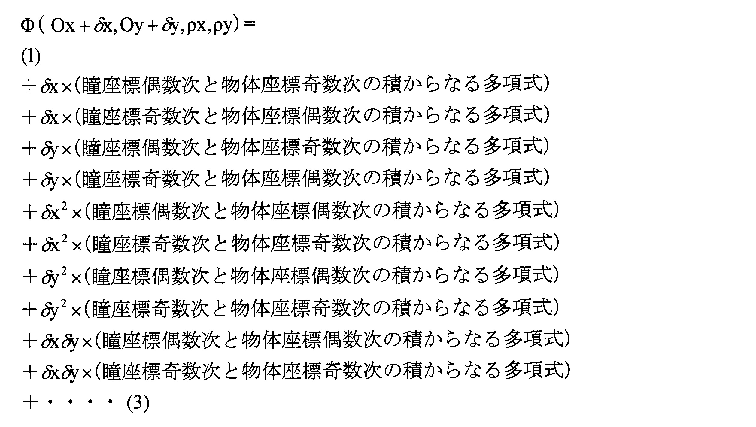










但し、
δkx+Jx、δky+Jyは、被検光学系のk面における投光光学系の軸基準の偏心量であって、被検光学系が公転軸から離れた位置に配置された状態において、与えられた公転シフトベクトル量を無視したときの偏心量、
sysは、システム収差、
Jx,Jyは、投光光学系の軸基準の公転軸の偏心量、
δkx、δkyは、自転軸基準の被検光学系の偏心量、
である。
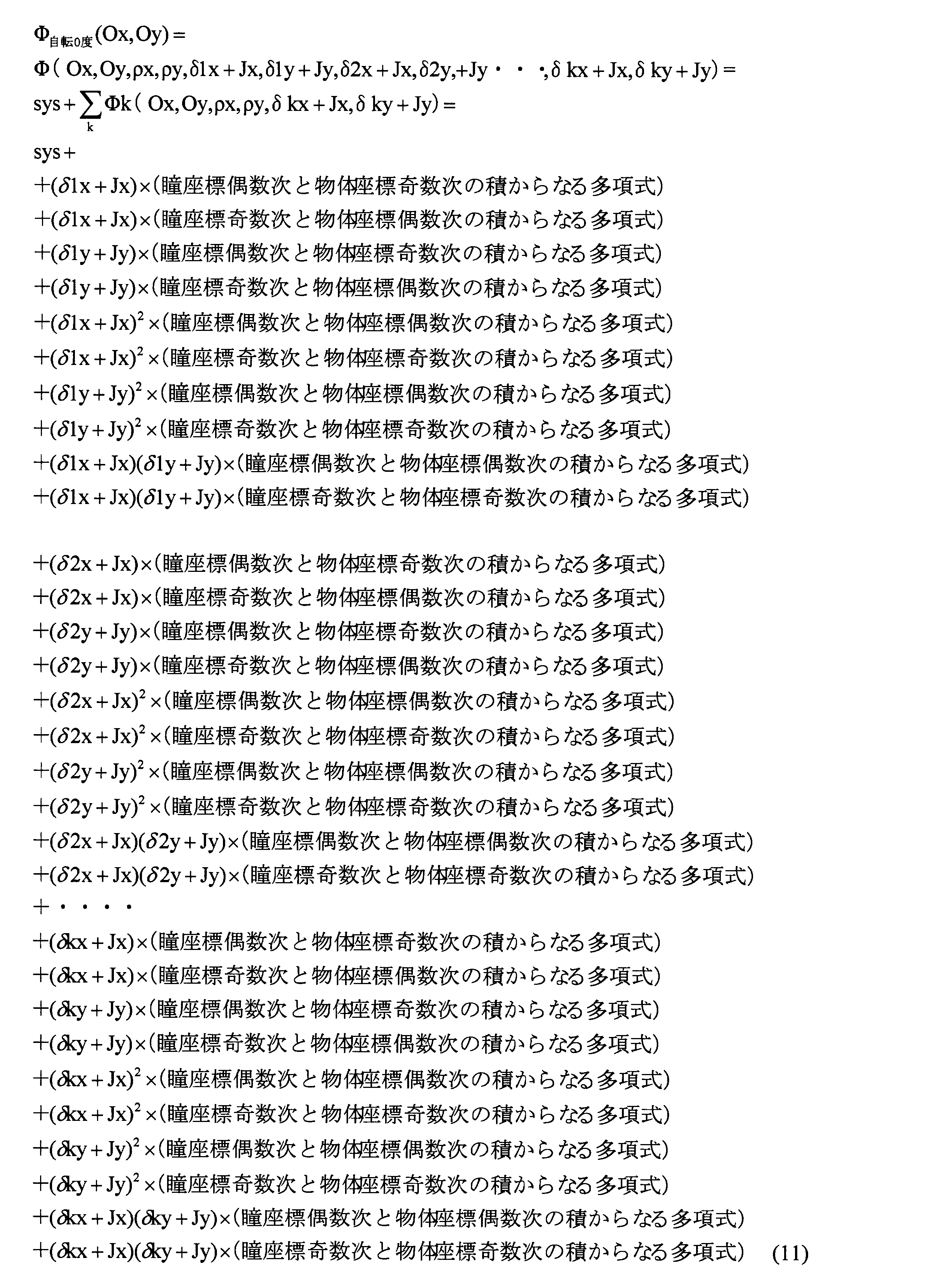

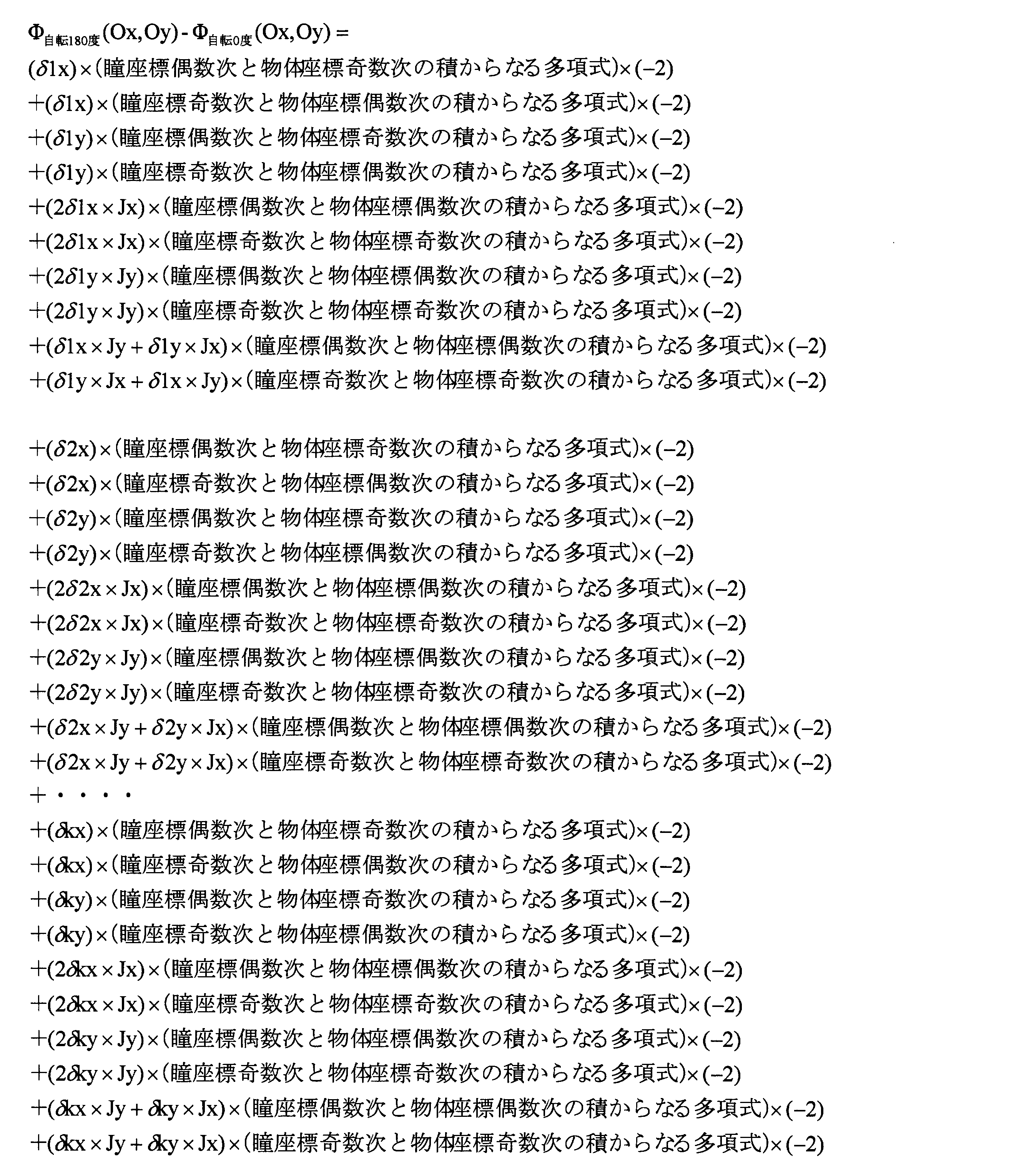
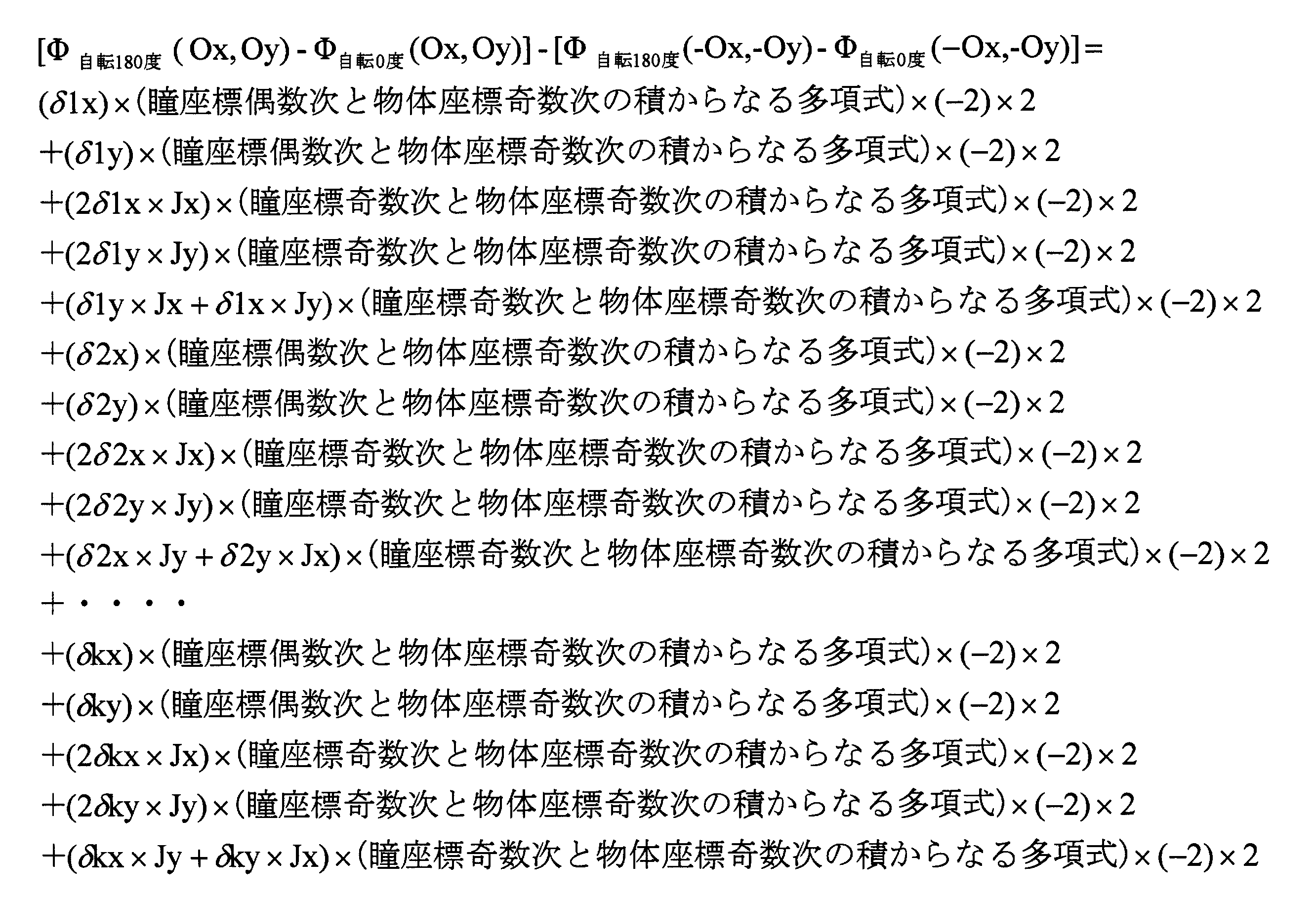


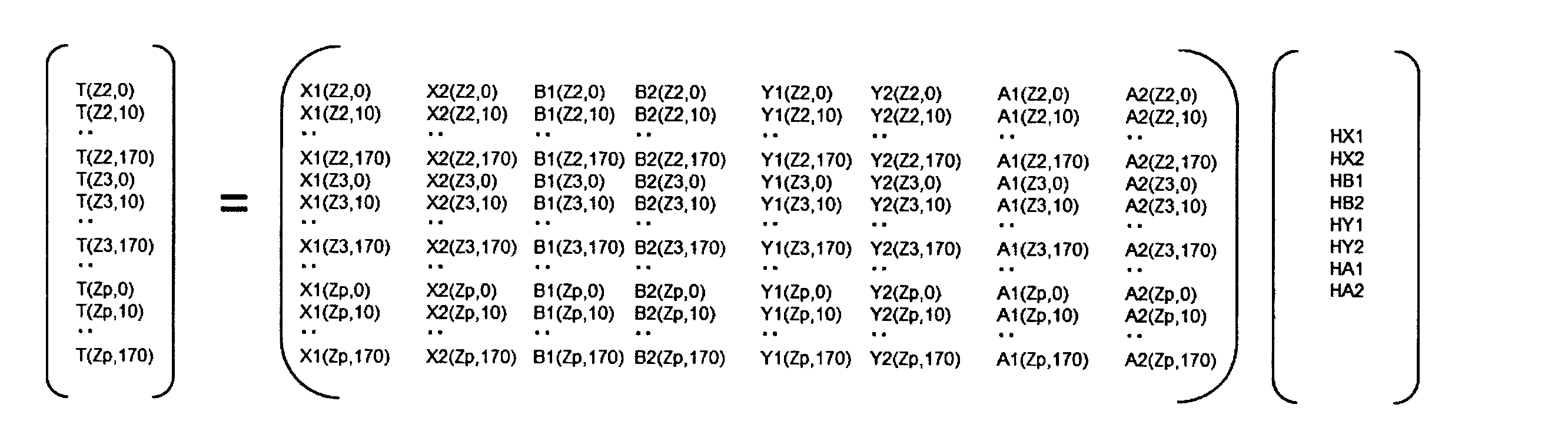

2 光源部
3 保持部、
4 受光光学系
5 波面測定部
6 波面データ生成部
7計測軸
8 ステージ
9 開口部
10、10’ 被検光学系
11 開口部の中心軸
12 開口部の中心
20、23 被検光学系
21、24、25、26 レンズ
22 レンズ枠
27 鏡筒
30 シャックハルトマンセンサー
31 マイクロレンズアレイ
32 撮像素子
40 第1の移動機構
41、42 移動ステージ
43、44、45、46 領域
47 移動軌跡
50 レンズ面
51 第1のパターン
52 第2のパターン
53 基準位置
60 波面計測装置
61 受光光学系
62、63 レンズ
70 波面計測装置
71、75 投光光学系
72、73、76、77 レンズ
74 光学絞り
80 第2の移動機構
90 前後反転機構構
91 回転ステージの中心軸
92 波面計測装置の本体部
93 枠部材
100 波面計測装置
101 本体部
102、103、104、105 保持部材
110 演算処理部
111 プログラム記憶部
112 データ記憶部
113 第1の移動機構制御部
114 第2の移動機構制御部
121 第1の波面データ取得制御部
122 第2の波面データ取得制御部
130 波面変化データ解析部
140 収差成分量抽出解析部
150 自転軸基準偏心量算出部
200、201、202、203 球心
210 新たな軸
220 球心
L1、L1’、L2、L2’、L3、L3’、L4、L4’ 光束
H1、H2、H3 凸部
L1、L2、L3 凹部
SP1 第1の面頂位置
SP2 第2の面頂位置
S レンズ面
δ1、δ2、δ3、δ4 偏心量
X、Y、A、B 偏心自由度
Claims (20)
- 光源部と、保持部と、受光光学系と、波面測定部と、波面データ生成部と、を有し、
前記光源部は、計測軸の一方の側に配置され、
前記波面測定部は、前記計測軸の他方の側に配置され、
前記保持部は、前記光源部と前記波面測定部との間に配置され、
前記受光光学系は、前記保持部と前記波面測定部との間に配置され、
前記保持部は、被検光学系を保持する開口部を有し、
前記光源部から前記被検光学系に向けて光束を照射し、
前記波面測定部で、前記被検光学系を透過した光束を測定し、
前記波面データ生成部で、前記波面測定部で測定した結果から波面収差データを生成する波面計測装置であって、
前記受光光学系によって、前記開口部近傍と前記波面測定部近傍とが光学的に共役になっており、
前記光束の測定は、前記開口部の中心を前記計測軸から所定の距離だけ離した状態での測定を少なくとも含むことを特徴とする波面計測装置。 - 光源部と、保持部と、第1の移動機構と、受光光学系と、波面測定部と、波面データ生成部と、を有し、
前記光源部は、計測軸の一方の側に配置され、
前記波面測定部は、前記計測軸の他方の側に配置され、
前記保持部は、前記光源部と前記波面測定部との間に配置され、
前記受光光学系は、前記保持部と前記波面測定部との間に配置され、
前記保持部は、被検光学系を保持する開口部を有し、
前記光源部から前記被検光学系に向けて光束を照射し、
前記波面測定部で、前記被検光学系を透過した光束を測定し、
前記波面データ生成部で、前記波面測定部で測定した結果から波面収差データを生成する波面計測装置であって、
前記受光光学系によって、前記開口部近傍と前記波面測定部近傍とが光学的に共役になっており、
前記第1の移動機構は、前記計測軸の周りの複数の位置に前記被検光学系を移動させ、
前記被検光学系における前記光束の透過領域は、前記複数の位置の各々で異なり、
前記波面測定部は、前記被検光学系を透過した光束を、前記複数の位置の各々で測定し、
前記波面データ生成部は、前記複数の位置の各々で測定した結果から前記波面収差データを生成することを特徴とする波面計測装置。 - 前記開口部が前記波面測定部と共役となるように、前記開口部と、前記受光光学系と、前記波面測定部と、が位置決めされていることを特徴とする請求項1又は2に記載の波面計測装置。
- 前記被検光学系の後側主点が前記波面測定部と共役となるように、前記開口部と、前記受光光学系と、前記波面測定部と、が位置決めされていることを特徴とする請求項1又は2に記載の波面計測装置。
- 前記受光光学系は、最も光源部側に位置する前側光学系と、最も波面測定部側に位置する後側光学系と、を少なくとも有し、
前記前側光学系の後側焦点位置と前記後側光学系の前側焦点位置とが一致又は共役になっていることを特徴とする請求項1から4のいずれか一項に記載の波面計測装置。 - 前記光源部と前記保持部の間に投光光学系を有することを特徴とする請求項1から5のいずれか一項に記載の波面計測装置。
- 前記投光光学系は、前記受光光学系と共軸となっていることを特徴とする請求項1から6のいずれか一項に記載の波面計測装置。
- 前記投光光学系は、集光光束を生成することを特徴とする請求項1から7のいずれか一項に記載の波面計測装置。
- 前記集光光束の集光点の位置が前記被検光学系の前側焦点位置と一致するように、前記投光光学系と前記保持部とが位置決めされていることを特徴とする請求項1から8のいずれか一項に記載の波面計測装置。
- 前記投光光学系は前記計測軸方向に駆動可能なことを特徴とする請求項1から9のいずれか一項に記載の波面計測装置。
- 前記投光光学系はズームレンズであることを特徴とする請求項1から10のいずれか一項に記載の波面計測装置。
- 前記第1の移動機構は、前記被検光学系を回転させて前記透過領域を変化させることを特徴とする請求項1から11のいずれか一項に記載の波面計測装置。
- 前記第1の移動機構は前記計測軸に対して前記被検光学系を公転軌道で移動させ、
前記波面測定部は、前記公転軌道での移動中に前記波面収差データを取得することを特徴とする請求項1から12のいずれか一項に記載の波面計測装置。 - 第2の移動機構を有し、
前記第2の移動機構は前記被検光学系を自転させることを特徴とする請求項1から13のいずれか一項に記載の波面計測装置。 - 自転前波面データ取得制御部と、自転後波面データ取得制御部と、波面変化データ解析部と、を有し、
第1の状態は、前記第2の移動機構による自転を実施する前の状態であり、
第2の状態は、前記第2の移動機構による自転を実施した後の状態であり、
前記自転前波面データ取得制御部は、前記第1の状態で、前記計測軸に対して前記被検光学系を公転軌道で動かして、前記公転軌道中の前記複数の位置の各々で取得した波面収差データを保存し、
前記自転後波面データ取得制御部は、前記第2の状態で、前記計測軸に対して前記被検光学系を公転軌道で動かして、前記公転軌道中の前記複数の位置の各々で取得した波面収差データを保存し、
前記波面変化データ解析部は、前記第1の状態で取得した波面収差データを参照波面データとし、前記第2の状態で取得した波面収差データを測定波面データとし、自転に伴う波面収差変化データを取得することを特徴とする請求項1から14のいずれか一項に記載の波面計測装置。 - 前記波面変化データ解析部は、前記複数の位置の各々で取得した波面収差変化データについてゼルニケフィッティングを実施し、各取得位置でのゼルニケ波面収差変化データを取得することを特徴とする請求項15に記載の波面計測装置。
- 収差成分量抽出解析部を有し、
前記収差成分量抽出解析部は、前記各状態で得られたゼルニケ波面収差変化データについて、前記計測軸周りに180度対称なゼルニケ波面収差変化データどうしで、ゼルニケ多項式の瞳座標が偶数次のゼルニケ係数について差をとり、ゼルニケ多項式の瞳座標が奇数次のゼルニケ係数について和をとり、第1の収差成分を抽出することを特徴とすることを特徴とする16に記載の波面計測装置。 - 前後反転機構を有し、
前記前後反転機構は、前記計測軸と直交する軸を回転軸として前記被検光学系を回転させることを特徴とする請求項1から17のいずれか一項に記載の波面計測装置。 - 自転軸基準偏心量算出部を有し、
前記自転軸基準偏心量算出部は、解析された被検光学系の各面の各偏心自由度の変位量から自転軸基準の被検光学系の偏心量を算出することを特徴とする請求項1から18のいずれか一項に記載の波面計測装置。 - 被検光学系近傍と波面測定部近傍とを光学的共役関係にする工程と、
波面計測装置の計測軸に対して前記被検光学系を偏心させる偏心駆動工程と、
波面測定部と波面データ生成部が、前記被検光学系を透過した光束の波面収差データを取得する波面データ取得工程と、
を有することを特徴とする波面計測方法。
Priority Applications (5)
| Application Number | Priority Date | Filing Date | Title |
|---|---|---|---|
| PCT/JP2015/059806 WO2016157344A1 (ja) | 2015-03-27 | 2015-03-27 | 波面計測装置及び波面計測方法 |
| CN201580077921.0A CN107430046B (zh) | 2015-03-27 | 2015-03-27 | 波面计测装置和波面计测方法 |
| JP2017508870A JP6426274B2 (ja) | 2015-03-27 | 2015-03-27 | 波面計測装置及び波面計測方法 |
| DE112015006198.3T DE112015006198T5 (de) | 2015-03-27 | 2015-03-27 | Wellenfrontmessvorrichtung und wellenfrontmessverfahren |
| US15/717,744 US10444112B2 (en) | 2015-03-27 | 2017-09-27 | Wavefront measurement apparatus and wavefront measurement method |
Applications Claiming Priority (1)
| Application Number | Priority Date | Filing Date | Title |
|---|---|---|---|
| PCT/JP2015/059806 WO2016157344A1 (ja) | 2015-03-27 | 2015-03-27 | 波面計測装置及び波面計測方法 |
Related Child Applications (1)
| Application Number | Title | Priority Date | Filing Date |
|---|---|---|---|
| US15/717,744 Continuation US10444112B2 (en) | 2015-03-27 | 2017-09-27 | Wavefront measurement apparatus and wavefront measurement method |
Publications (1)
| Publication Number | Publication Date |
|---|---|
| WO2016157344A1 true WO2016157344A1 (ja) | 2016-10-06 |
Family
ID=57006925
Family Applications (1)
| Application Number | Title | Priority Date | Filing Date |
|---|---|---|---|
| PCT/JP2015/059806 Ceased WO2016157344A1 (ja) | 2015-03-27 | 2015-03-27 | 波面計測装置及び波面計測方法 |
Country Status (5)
| Country | Link |
|---|---|
| US (1) | US10444112B2 (ja) |
| JP (1) | JP6426274B2 (ja) |
| CN (1) | CN107430046B (ja) |
| DE (1) | DE112015006198T5 (ja) |
| WO (1) | WO2016157344A1 (ja) |
Cited By (2)
| Publication number | Priority date | Publication date | Assignee | Title |
|---|---|---|---|---|
| TWI637147B (zh) * | 2017-09-15 | 2018-10-01 | 東大光電股份有限公司 | Wavefront measurement system |
| JP2023006310A (ja) * | 2021-06-30 | 2023-01-18 | 株式会社Screenホールディングス | 光学レンズ検査装置、および光学レンズ検査方法 |
Families Citing this family (3)
| Publication number | Priority date | Publication date | Assignee | Title |
|---|---|---|---|---|
| JP6914484B2 (ja) * | 2018-03-14 | 2021-08-04 | オムロン株式会社 | 光電センサ及びセンサシステム |
| CN110057543B (zh) * | 2019-04-24 | 2020-12-11 | 暨南大学 | 基于同轴干涉的波面测量装置 |
| US20240085268A1 (en) * | 2022-09-14 | 2024-03-14 | National Central University | Optical wavefront measuring device and measuring method thereof |
Citations (3)
| Publication number | Priority date | Publication date | Assignee | Title |
|---|---|---|---|---|
| JP2005158829A (ja) * | 2003-11-20 | 2005-06-16 | Nikon Corp | 波面収差計測方法及び装置、並びに露光装置 |
| JP2014020881A (ja) * | 2012-07-17 | 2014-02-03 | Olympus Corp | レンズ検査装置およびレンズ検査方法 |
| JP5452032B2 (ja) * | 2009-02-13 | 2014-03-26 | 株式会社日立製作所 | 波面収差測定方法及びその装置 |
Family Cites Families (10)
| Publication number | Priority date | Publication date | Assignee | Title |
|---|---|---|---|---|
| US6819414B1 (en) * | 1998-05-19 | 2004-11-16 | Nikon Corporation | Aberration measuring apparatus, aberration measuring method, projection exposure apparatus having the same measuring apparatus, device manufacturing method using the same measuring method, and exposure method |
| WO2002054036A1 (en) * | 2000-12-28 | 2002-07-11 | Nikon Corporation | Imaging characteristics measuring method, imaging characteriatics adjusting method, exposure method and system, program and recording medium, and device producing method |
| DE10146499B4 (de) * | 2001-09-21 | 2006-11-09 | Carl Zeiss Smt Ag | Verfahren zur Optimierung der Abbildungseigenschaften von mindestens zwei optischen Elementen sowie Verfahren zur Optimierung der Abbildungseigenschaften von mindestens drei optischen Elementen |
| JP4738949B2 (ja) * | 2005-09-15 | 2011-08-03 | 富士フイルム株式会社 | 光波干渉装置 |
| CN101278190B (zh) * | 2005-09-29 | 2012-12-19 | 奥林巴斯株式会社 | 焦点位置决定方法、焦点位置决定装置、微弱光检测装置及微弱光检测方法 |
| CN101126675B (zh) * | 2006-08-18 | 2011-02-23 | 中国科学院长春光学精密机械与物理研究所 | 具有时空连续性的tft液晶湍流模拟器 |
| JP4974717B2 (ja) * | 2007-03-12 | 2012-07-11 | オリンパス株式会社 | 顕微鏡の補正環付対物レンズの補正環駆動装置 |
| CN101772696A (zh) * | 2007-08-27 | 2010-07-07 | 株式会社尼康 | 波面像差测量装置及方法、以及波面像差调整方法 |
| CN102844651B (zh) * | 2010-04-05 | 2015-07-01 | 株式会社尼康 | 波前像差测定装置 |
| US10209161B2 (en) * | 2014-07-03 | 2019-02-19 | National Applied Research Laboratories | Measuring optical element for aberration from gravity and holding |
-
2015
- 2015-03-27 JP JP2017508870A patent/JP6426274B2/ja active Active
- 2015-03-27 DE DE112015006198.3T patent/DE112015006198T5/de not_active Withdrawn
- 2015-03-27 CN CN201580077921.0A patent/CN107430046B/zh active Active
- 2015-03-27 WO PCT/JP2015/059806 patent/WO2016157344A1/ja not_active Ceased
-
2017
- 2017-09-27 US US15/717,744 patent/US10444112B2/en active Active
Patent Citations (3)
| Publication number | Priority date | Publication date | Assignee | Title |
|---|---|---|---|---|
| JP2005158829A (ja) * | 2003-11-20 | 2005-06-16 | Nikon Corp | 波面収差計測方法及び装置、並びに露光装置 |
| JP5452032B2 (ja) * | 2009-02-13 | 2014-03-26 | 株式会社日立製作所 | 波面収差測定方法及びその装置 |
| JP2014020881A (ja) * | 2012-07-17 | 2014-02-03 | Olympus Corp | レンズ検査装置およびレンズ検査方法 |
Cited By (5)
| Publication number | Priority date | Publication date | Assignee | Title |
|---|---|---|---|---|
| TWI637147B (zh) * | 2017-09-15 | 2018-10-01 | 東大光電股份有限公司 | Wavefront measurement system |
| CN109506897A (zh) * | 2017-09-15 | 2019-03-22 | 东大光电股份有限公司 | 波前量测系统 |
| CN109506897B (zh) * | 2017-09-15 | 2020-10-16 | 东大光电股份有限公司 | 波前量测系统 |
| JP2023006310A (ja) * | 2021-06-30 | 2023-01-18 | 株式会社Screenホールディングス | 光学レンズ検査装置、および光学レンズ検査方法 |
| JP7648456B2 (ja) | 2021-06-30 | 2025-03-18 | 株式会社Screenホールディングス | 光学レンズ検査装置、および光学レンズ検査方法 |
Also Published As
| Publication number | Publication date |
|---|---|
| US20180073957A1 (en) | 2018-03-15 |
| CN107430046A (zh) | 2017-12-01 |
| US10444112B2 (en) | 2019-10-15 |
| JP6426274B2 (ja) | 2018-11-21 |
| DE112015006198T5 (de) | 2017-11-09 |
| JPWO2016157344A1 (ja) | 2018-01-25 |
| CN107430046B (zh) | 2019-08-30 |
Similar Documents
| Publication | Publication Date | Title |
|---|---|---|
| JP6426274B2 (ja) | 波面計測装置及び波面計測方法 | |
| JP6072317B2 (ja) | 偏心量計測方法及び偏心量計測装置 | |
| CN106646867B (zh) | 一种深紫外光学系统共焦对准装置与方法 | |
| JP2001275972A (ja) | 眼光学特性測定装置 | |
| JP2010281792A (ja) | 非球面体測定方法および装置 | |
| CN102087097A (zh) | 非球面体测定方法以及装置 | |
| JP2009229144A (ja) | 偏心測定機 | |
| JP5904896B2 (ja) | レンズ検査装置およびレンズ検査方法 | |
| CN111044259B (zh) | 光学镜头的间距、偏心和波前像差一体化测量系统 | |
| JPH0996589A (ja) | レンズ性能測定方法及びそれを用いたレンズ性能測定装置 | |
| JP6685741B2 (ja) | 形状計測方法、形状計測装置、プログラム、記録媒体及び光学素子の製造方法 | |
| JP2005214879A (ja) | 非球面偏心測定装置、非球面偏心測定方法、及びそれらに用いる非球面レンズ | |
| JP2016136120A (ja) | 形状測定方法および形状測定装置 | |
| JP2005024504A (ja) | 偏心測定方法、偏心測定装置、及びこれらにより測定された物 | |
| RU2166904C1 (ru) | Кератометр | |
| JP4190044B2 (ja) | 偏心測定装置 | |
| JP2005147703A (ja) | 面間隔測定装置および面間隔測定方法 | |
| JP2007010609A (ja) | 非球面レンズ製造方法、非球面レンズの偏心測定方法、偏心測定装置及びこの方法により製造された非球面レンズ | |
| JP5317619B2 (ja) | 偏芯量測定方法 | |
| JP2012225705A (ja) | 光学測定装置及び光学測定方法 | |
| JPH11304641A (ja) | 波面収差測定方法及び波面収差測定装置 | |
| JPH11337306A (ja) | 干渉計測装置 | |
| JPS6244601A (ja) | 移動載置台装置 | |
| JPH05317259A (ja) | 眼科用測定機器 | |
| JP2004028613A (ja) | レンズ系の偏心測定装置 |
Legal Events
| Date | Code | Title | Description |
|---|---|---|---|
| 121 | Ep: the epo has been informed by wipo that ep was designated in this application |
Ref document number: 15887497 Country of ref document: EP Kind code of ref document: A1 |
|
| ENP | Entry into the national phase |
Ref document number: 2017508870 Country of ref document: JP Kind code of ref document: A |
|
| WWE | Wipo information: entry into national phase |
Ref document number: 112015006198 Country of ref document: DE |
|
| 122 | Ep: pct application non-entry in european phase |
Ref document number: 15887497 Country of ref document: EP Kind code of ref document: A1 |