WO2016157272A1 - 電気泳動装置および電気泳動方法 - Google Patents
電気泳動装置および電気泳動方法 Download PDFInfo
- Publication number
- WO2016157272A1 WO2016157272A1 PCT/JP2015/059532 JP2015059532W WO2016157272A1 WO 2016157272 A1 WO2016157272 A1 WO 2016157272A1 JP 2015059532 W JP2015059532 W JP 2015059532W WO 2016157272 A1 WO2016157272 A1 WO 2016157272A1
- Authority
- WO
- WIPO (PCT)
- Prior art keywords
- electrophoresis
- container
- capillary
- electrophoresis medium
- anode
- Prior art date
- Legal status (The legal status is an assumption and is not a legal conclusion. Google has not performed a legal analysis and makes no representation as to the accuracy of the status listed.)
- Ceased
Links
Images













Classifications
-
- G—PHYSICS
- G01—MEASURING; TESTING
- G01N—INVESTIGATING OR ANALYSING MATERIALS BY DETERMINING THEIR CHEMICAL OR PHYSICAL PROPERTIES
- G01N27/00—Investigating or analysing materials by the use of electric, electrochemical, or magnetic means
- G01N27/26—Investigating or analysing materials by the use of electric, electrochemical, or magnetic means by investigating electrochemical variables; by using electrolysis or electrophoresis
- G01N27/416—Systems
- G01N27/447—Systems using electrophoresis
-
- G—PHYSICS
- G01—MEASURING; TESTING
- G01N—INVESTIGATING OR ANALYSING MATERIALS BY DETERMINING THEIR CHEMICAL OR PHYSICAL PROPERTIES
- G01N27/00—Investigating or analysing materials by the use of electric, electrochemical, or magnetic means
- G01N27/26—Investigating or analysing materials by the use of electric, electrochemical, or magnetic means by investigating electrochemical variables; by using electrolysis or electrophoresis
- G01N27/416—Systems
- G01N27/447—Systems using electrophoresis
- G01N27/44704—Details; Accessories
- G01N27/44743—Introducing samples
-
- G—PHYSICS
- G01—MEASURING; TESTING
- G01N—INVESTIGATING OR ANALYSING MATERIALS BY DETERMINING THEIR CHEMICAL OR PHYSICAL PROPERTIES
- G01N27/00—Investigating or analysing materials by the use of electric, electrochemical, or magnetic means
- G01N27/26—Investigating or analysing materials by the use of electric, electrochemical, or magnetic means by investigating electrochemical variables; by using electrolysis or electrophoresis
- G01N27/416—Systems
- G01N27/447—Systems using electrophoresis
- G01N27/44704—Details; Accessories
- G01N27/44717—Arrangements for investigating the separated zones, e.g. localising zones
- G01N27/44721—Arrangements for investigating the separated zones, e.g. localising zones by optical means
-
- G—PHYSICS
- G01—MEASURING; TESTING
- G01N—INVESTIGATING OR ANALYSING MATERIALS BY DETERMINING THEIR CHEMICAL OR PHYSICAL PROPERTIES
- G01N27/00—Investigating or analysing materials by the use of electric, electrochemical, or magnetic means
- G01N27/26—Investigating or analysing materials by the use of electric, electrochemical, or magnetic means by investigating electrochemical variables; by using electrolysis or electrophoresis
- G01N27/416—Systems
- G01N27/447—Systems using electrophoresis
- G01N27/44756—Apparatus specially adapted therefor
-
- G—PHYSICS
- G01—MEASURING; TESTING
- G01N—INVESTIGATING OR ANALYSING MATERIALS BY DETERMINING THEIR CHEMICAL OR PHYSICAL PROPERTIES
- G01N27/00—Investigating or analysing materials by the use of electric, electrochemical, or magnetic means
- G01N27/26—Investigating or analysing materials by the use of electric, electrochemical, or magnetic means by investigating electrochemical variables; by using electrolysis or electrophoresis
- G01N27/416—Systems
- G01N27/447—Systems using electrophoresis
- G01N27/44756—Apparatus specially adapted therefor
- G01N27/44782—Apparatus specially adapted therefor of a plurality of samples
-
- G—PHYSICS
- G01—MEASURING; TESTING
- G01N—INVESTIGATING OR ANALYSING MATERIALS BY DETERMINING THEIR CHEMICAL OR PHYSICAL PROPERTIES
- G01N27/00—Investigating or analysing materials by the use of electric, electrochemical, or magnetic means
- G01N27/26—Investigating or analysing materials by the use of electric, electrochemical, or magnetic means by investigating electrochemical variables; by using electrolysis or electrophoresis
- G01N27/416—Systems
- G01N27/447—Systems using electrophoresis
- G01N27/44756—Apparatus specially adapted therefor
- G01N27/44791—Microapparatus
Definitions
- the present invention relates to an electrophoresis apparatus and an electrophoresis method for separating and analyzing nucleic acids and proteins.
- capillary electrophoresis apparatuses in which capillaries are filled with electrophoresis media such as polymer gels and polymer solutions have been widely used as electrophoresis apparatuses.
- a capillary electrophoresis apparatus as disclosed in Patent Document 1 has been conventionally used.
- This capillary electrophoresis apparatus has higher heat dissipation than the flat plate type electrophoresis apparatus, and can apply a higher voltage to the sample.
- it has many advantages such as a small amount of sample, automatic filling of the electrophoresis medium, and automatic sample injection, and it is used for various separation analysis measurements including analysis of nucleic acids and proteins.
- the electrophoresis medium is filled with a syringe pump.
- a relay channel block having a syringe pump function, and a capillary is connected, the electrophoresis medium is sucked by the syringe pump, and the capillary is discharged to be filled.
- a buffer solution for electrophoresis is connected to the relay channel block, and the channel is switched by opening and closing a valve in the relay channel block.
- the capillary electrophoresis apparatus it is necessary to replace the electrophoresis medium container and the capillary. However, at the time of replacement, a part of the relay channel block is exposed to air, so that air may be mixed in the channel.
- a high voltage of several to several tens of kV is applied across the flow path. For this reason, when air bubbles are present in the flow path, the flow path may be electrically blocked by the air bubbles.
- the flow path is electrically interrupted, a high voltage difference is generated at the interrupted location, causing discharge. Depending on the magnitude of this discharge, the capillary electrophoresis apparatus may be destroyed. Therefore, it is necessary to remove bubbles from the flow path before starting electrophoresis.
- the valve of the flow path connected to the buffer solution is opened, and the electrophoresis medium is flowed to the buffer solution side. Thereby, air bubbles are removed from the channel section in the relay channel block.
- the capillary is filled with an amount of electrophoresis medium about twice the internal volume of the capillary. At this time, the inner diameter of the capillary is as thin as about 50 ⁇ m. For this reason, bubbles flow through the capillary together with the electrophoresis medium and are discharged from the other end of the capillary. That is, bubbles can be removed from the inside of the capillary.
- the relay channel block may be damaged. In that case, repair of the damaged part is required, and a great deal of time is required until the inspection is resumed. Therefore, it is necessary for the user to check for the presence of bubbles.
- Patent Document 2 shows a mechanism that eliminates the need to visually check the bubbles in the relay flow path block and reduces the difficulty of operation of the electrophoresis apparatus.
- the electrophoresis medium container is a disposable electrophoresis medium container having a liquid feeding mechanism, and the flow path between the capillary, the electrophoresis medium, and the buffer is switched. Only when the electrophoresis medium is filled, the electrophoresis medium container and the capillary are connected, and during electrophoresis, the capillary is removed from the electrophoresis medium container, and both ends of the capillary are directly immersed in a buffer solution. That is, the relay flow path block itself becomes unnecessary.
- the amount of useless electrophoresis medium for removing bubbles is reduced, and there is no risk of bubbles being mixed at the time of electrophoresis, and it is possible to eliminate visual confirmation of bubbles by the user before electrophoresis.
- the damaged portion can be limited to the capillary.
- the capillary since the capillary is a consumable item, it does not require repair unlike the relay flow path block. That is, the inspection can be resumed only by replacing the capillary. For this reason, the time required to resume the inspection can be greatly shortened.
- connection portion with the capillary and the position of the liquid feeding mechanism have a high pressure resistance. This is because the inner diameter of the capillary is about 50 ⁇ m, and it is necessary to apply a pressure of several MPa in order to inject an electrophoresis medium having a viscosity several hundred times higher than water.
- the electrophoresis medium container it is necessary to check the remaining amount in the electrophoresis medium container and manage the amount of liquid fed with fine resolution as before.
- the resolution of the management of the liquid supply amount becomes rough, the liquid supply amount for determining that the electrophoresis medium can be filled in the capillary increases.
- an electrophoresis medium for removing bubbles is unnecessary, but the amount of electrophoresis medium for filling the capillaries increases, and as a result, the necessary amount of electrophoresis medium increases. As a result, the running cost cannot be reduced.
- An object of the present invention is to provide a capillary electrophoresis apparatus that achieves these problems.
- the electrophoresis apparatus of the present invention is an electrophoresis apparatus for feeding a sample into a capillary by electrophoresis and optically detecting the sample.
- Capillary A capillary head provided at the tip of the capillary;
- a guide member that covers the side surface of the electrophoresis medium filling container;
- a seal member for sealing the electrophoresis medium filled in the electrophoresis medium filling container from below; And a plunger that presses the seal member.
- the expansion of the electrophoresis medium container can be suppressed, a high pressure resistant container can be obtained. Further, these can be realized by an electrophoresis medium container having an inexpensive liquid feeding function. This makes it possible to reduce running costs and improve user workability.
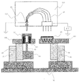
- Device configuration schematic diagram of the present invention Device top view of the present invention AA cross section of the device Detailed view of pumping mechanism Detailed view of capillary array Detailed view of anode buffer container Detailed view of cathode buffer Detailed view of sample container Detailed view of electrophoresis medium container Detailed mounting diagram of electrophoresis medium container Connection diagram of capillary array and cathode buffer container Connection diagram of capillary array and anode buffer container Connection diagram of capillary array and electrophoresis medium container Analysis workflow in this example Detailed operation of capillary head cleaning (initial cleaning) Detail of capillary head cleaning operation (buffer solution contact) Detailed operation of capillary head cleaning operation (buffer cleaning) Electrophoresis medium feeding operation details (initial state) Detailed operation diagram of electrophoretic medium feeding (plunger contact detection) Electrophoretic medium feeding operation details (capillary connection) Electrophoretic medium feeding operation details (electrophoresis medium injection) Electrophoretic medium feeding operation details (Plunger contact release) Detailed operation diagram of
- the fluid sealing portion in the electrophoresis medium container has a shape that forms an internal pressure sealing structure that is more sealed when the internal pressure increases.
- a function for detecting the remaining amount of the electrophoresis medium container is provided on the apparatus side, and a function for removing the internal pressure in the electrophoresis medium container after liquid feeding is provided. Thereby, it is possible to manage the remaining amount in the electrophoresis medium container and the liquid supply amount.
- the electrophoresis medium container has a syringe structure like a syringe and is set on a guide component for suppressing its own expansion.
- This guide component has high rigidity, and when the migration medium container expands, it expands until it comes into contact with the guide component, and further expansion is suppressed.
- the electrophoresis medium container and capillary are connected by bundling a plurality of capillaries together and providing a capillary head with a sharpened tip.
- the electrophoresis medium container has a rubber plug, and the capillary head penetrates the rubber plug. Let them be connected. At this time, the capillary head is pressed against the rubber plug so as to suppress the expansion of the rubber plug due to the liquid feeding pressure with the capillary head.
- the syringe medium electrophoresis medium container has a built-in movable seal part for feeding liquid.
- the sealing surface of the sealing component is shaped and thickened so as to be more easily deformed by the internal pressure than the container syringe. Further, by making the shape of the sealing part concave inward of the container and using the concave tip as a sealing surface, an internal pressure sealing structure that is more sealed when the internal pressure increases is obtained.
- the liquid feeding of the electrophoresis medium is performed by pushing the seal part of the electrophoresis medium container from the outside.
- the liquid feeding mechanism including a plunger that pushes the seal part is provided with an encoder so as to detect a change in speed when the plunger contacts the seal part.
- a force is exerted to return the seal part to the original position. In that state, the plunger that has been in contact with the seal part is once released. As a result, the seal component moves in the direction of the original position, and the internal pressure of the electrophoresis medium container is removed.
- the expansion of the electrophoresis medium container can be suppressed, a high pressure resistant container can be obtained. Furthermore, by detecting the position of the seal component in the electrophoresis medium container and removing the residual pressure in the electrophoresis medium container, it is possible to manage the remaining amount and the liquid feeding amount in the electrophoresis medium container. Further, these can be realized by an electrophoresis medium container having an inexpensive liquid feeding function. This makes it possible to reduce running costs and improve user workability.
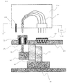
- FIG. 1 shows an apparatus configuration diagram of a capillary electrophoresis apparatus to which the present invention is applied.
- This apparatus can be roughly divided into two units: an autosampler unit 150 at the lower part of the apparatus and an irradiation detection / constant temperature chamber unit 160 at the upper part of the apparatus.
- a Y-axis drive body 85 is mounted on the sampler base 80 and can be driven in the Y-axis.
- a Z-axis drive body 90 is mounted on the Y-axis drive body 85 and can drive the Z-axis.
- a sample tray 100 is mounted on the Z-axis driver 90, and the user sets the electrophoresis medium container 20, the anode buffer container 30, the cathode buffer container 40, and the sample container 50 on the sample tray 100. .
- the sample container 50 is set on an X-axis driver 95 mounted on the sample tray 100, and only the sample container 50 can be driven on the X-axis on the sample tray 100.
- a liquid feeding mechanism 60 is also mounted on the Z-axis drive body 90. The liquid feeding mechanism 60 is disposed below the electrophoresis medium container 20.
- the irradiation detection / constant temperature chamber unit 160 includes a constant temperature chamber unit 110 and a constant temperature chamber door 120, and the inside can be maintained at a constant temperature.
- An irradiation detection unit 130 is mounted behind the thermostatic chamber unit 110, and detection during electrophoresis can be performed.
- the capillary array 10 is set by the user in the thermostat unit 110, and electrophoresis is performed while the capillary array 10 is kept at a constant temperature in the thermostat unit 110, and detection is performed by the irradiation detection unit 130.
- the thermostatic chamber unit 110 is also equipped with an electrode 115 for dropping to GND when a high voltage for electrophoresis is applied.
- the capillary array 10 is fixed to the thermostat unit 110.
- the electrophoresis medium container 20, the anode buffer container 30, the cathode buffer container 40, and the sample container 50 can be driven on the YZ axis by the autosampler unit 150, and only the sample container 50 is further driven on the X axis. I can do it.
- the electrophoresis medium container 20, the anode buffer solution container 30, the cathode buffer solution container 40, and the sample container 50 can be automatically connected to the fixed capillary array 10 at any position by the movement of the autosampler unit 150. .
- FIG. 2 shows a view of the capillary electrophoresis apparatus as viewed from above.
- the anode side buffer solution container 30 set on the sample tray 100 includes an anode side cleaning layer 31, an anode side electrophoresis buffer layer 32, and a sample introduction buffer layer 33.
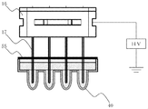
- the cathode side buffer container 40 includes a waste liquid layer 41, a cathode side cleaning layer 42, and a cathode side electrophoresis buffer layer 43.
- the electrophoresis medium container 20, the anode buffer container 30, the cathode buffer container 40, and the sample container 50 are arranged in a positional relationship as shown in the figure.
- the positional relationship between the anode side and the cathode side when connected to the capillary array 10 is “electrophoresis medium container 20—waste liquid layer 41”, “anode side cleaning layer 31—cathode side cleaning layer 42”, “anode side”.
- Electrophoresis buffer layer 32 cathode side electrophoresis buffer layer 43 ”,“ sample introduction buffer layer 33—sample container 50 ”.
- FIG. 3 is a cross-sectional view taken along the line AA in FIG.
- the electrophoresis medium container 20 is set by being inserted into a guide 101 embedded in the sample tray 100. Further, the liquid feeding mechanism 60 is arranged such that the plunger 61 built in the liquid feeding mechanism 60 is located below the electrophoresis medium container 20.
- the right side in FIG. 3 of the capillary array 10 is the cathode side, and the left side is the anode side.
- the autosampler unit 150 moves to the position of “anode-side electrophoresis buffer layer 32-cathode-side electrophoresis buffer layer 43”, a high voltage is applied to the cathode-side capillary array 10, and the cathode-side buffer container 40 is moved. Electrophoresis is performed by flowing to GND at the electrode 115 through the anode buffer solution container 30.
- FIG. 4 shows a detailed view of the liquid feeding mechanism 60.
- a stepping motor 62 with a rotary encoder 63 is mounted on the liquid feeding mechanism base 70, and a driving pulley 67 is attached to the stepping motor 62.
- the stepping motor 62 is a two-phase stepping motor and the rotary encoder 63 can count 400 per rotation.
- the drive pulley 67 and the passive pulley 68 are connected by a belt 69, and the passive pulley 68 and the ball screw 65 are fixed.
- a linear guide 66 is attached to the liquid feed mechanism base 70 in parallel with the ball screw 65, and the linear guide 66 and the ball screw 65 are fixed by a slider 71.
- a detection plate 72 is attached to the slider 71, and origin detection is performed by shielding the origin sensor 64 with the detection plate 72.
- the slider 71 has a plunger 61 facing the same axis direction as the drive shaft. Thereby, the plunger 61 can be driven by rotating the stepping motor 62.
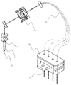
- FIG. 5 shows a detailed view of the capillary array 10.
- the capillary array 10 includes a capillary 11 which is a glass tube having an inner diameter of about ⁇ 50 ⁇ m, and a detection unit 12 is attached to the capillary 11.
- the detection unit 12 is detected by the irradiation detection unit 130.
- a load head 16 and a SUS pipe 17 are attached to the cathode side end of the capillary 11.
- the material of the load header 16 is preferably, for example, a PBT resin that is a resin having high insulation characteristics and a high comparative tracking index.
- a part that conducts all of the SUS pipe 17 is built in the load header 16, and a high voltage is applied to all the SUS pipes 17 by applying a high voltage thereto.
- the capillaries 11 are passed through the SUS pipes 17 and fixed. On the anode side, a plurality of capillaries 11 are combined into one by a capillary head 13.
- the capillary head 13 includes a capillary head tip 15 that has an acute angle and a needle shape, and a capillary head boss 14 that has a larger outer diameter than the capillary head tip 15.
- the material of the capillary head 13 is preferably PEEK resin which is hard to be chipped and has rigidity and is highly stable to chemicals and analysis.
- the detection unit 12 performs positioning with high accuracy so that the detection unit 12 can be detected by the irradiation detection unit.
- the load head 16 is fixed so as to be electrically connected to a portion to which a high voltage is applied when fixing.
- the capillary head 13 is firmly fixed so that the tip 15 of the capillary head faces directly below and can withstand the load.
- the positional relationship between the cathode side and the anode side at the time of fixing is such that a plurality of capillaries 11 do not overlap each other when set in the apparatus.
- FIG. 6 shows a detailed view of the anode side buffer container 30.
- the anode-side buffer container 30 includes the anode-side cleaning layer 31, the anode-side electrophoresis buffer layer 32, and the sample introduction buffer layer 33. It is a single container and is partitioned by a partition 56.
- the anode buffer solution container 30 is preferably made of a PC resin or the like which is a transparent resin so that the buffer solution therein can be visually observed.
- Cross sections of the anode-side cleaning layer 31, the anode-side electrophoresis buffer layer 32, and the sample introduction buffer layer 33 are shown in the BB, CC, and DD sectional views.
- the upper surface of the anode-side buffer solution container 30 is sealed with a film 55.
- the material of the film 55 is preferably a material that can be welded to the PC resin and can suppress water vapor permeation. Further, there is an operation of expanding the hole in the cleaning operation to be performed later. Considering this hole expansion operation, the film 55 needs to be made of a material that is difficult to stretch, and therefore, it is desirable that an aluminum layer be included.
- An anode-side cleaning solution 35, an anode-side electrophoresis buffer solution 36, and a sample introduction buffer solution 37 are sealed therein. Each liquid has a capacity capable of analyzing 10 RUN.
- the anode side cleaning layer 31 has a deeper container bottom than the anode side electrophoresis buffer layer 32 and the sample introduction buffer layer 33.
- FIG. 7 shows a detailed view of the cathode side buffer container 40.
- the cathode side buffer container 40 includes the waste liquid layer 41, the cathode side washing layer 42, and the cathode side electrophoresis buffer layer 43. It is a single container and is partitioned by a partition 56.
- the cathode buffer container 40 is preferably made of a PC resin or the like, which is a transparent resin so that the buffer solution therein can be visually observed, like the anode buffer container 30.
- Cross sections of the waste liquid layer 41, the cathode side cleaning layer 42, and the cathode side electrophoresis buffer layer 43 are shown in the EE cross section, the FF cross section, and the GG cross section.
- the upper surface of the cathode buffer solution container 40 is sealed with a film 55 in the same manner as the anode buffer solution container 30.
- Each layer has the same shape, and a waste liquid receiving liquid 45, a cathode side cleaning liquid 46, and a cathode side electrophoresis buffer 47 are sealed therein.
- Each liquid has a capacity capable of analyzing 10 RUN.
- the upper part of the partition 56 is also sealed with the film 55, so that the reagent is not mixed.
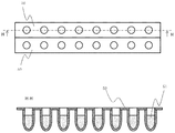
- FIG. 8 shows a detailed view of the sample container 50.
- the HH sectional view is a sectional view of the sample container 50, in which the sample 51 is enclosed. Since the sample 51 is prepared by the user, the sample container 50 is preferably a container that is easy to handle even in a pretreatment process or the like. In this apparatus, the sample container 50 is, for example, an eppendorf octal tube. Although illustration is omitted, when the sample container 50 is set in the apparatus, it is set in the apparatus as it is.
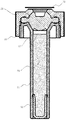
- FIG. 9 shows a detailed view of the swimming medium container 20.
- the electrophoresis medium container 20 has a concave seal 22 built in a syringe 21, and a rubber plug 23 is put on from above and sealed with a cap 24.
- the cap 24 is further sealed with a film 55.
- the material of the syringe 21 is preferably PP resin, which is a resin that can be molded thinly.
- the material of the seal 22 is preferably an ultra-high molecular PE resin that is often used for sealing a fluid in a sliding portion and has excellent sliding characteristics.
- the material of the rubber plug 23 is preferably silicon rubber or the like that is stable against analysis.
- the material of the cap 24 is preferably PC resin or the like in order to unify with the film 55 of each container.
- the electrophoresis medium 26 is sealed, and the air 27 that enters during the sealing is sealed so as to accumulate at the top.
- the electrophoresis medium 26 has a capacity capable of analyzing 10 RUN.
- the seal 22 can move the inside of the syringe 21 by applying a load from the outside.
- FIG. 10 shows a detailed view of the mounting of the electrophoresis medium container 20.
- the film 55 attached to the cap 24 is peeled off. Then, it inserts in the guide 101 embedded in the sample tray 100, and fixes from above so that it may not float up.
- the gap between the outer diameter of the syringe 21 and the inner diameter of the guide 101 is made as small as possible. The smaller the gap is, the better.
- the gap between the outer diameter of the syringe 21 that is a resin molded product and the inner diameter of the guide 101 that is a machined product is a reasonable clearance. Specifically, it is about 0.1 mm.
- FIG. 11 shows a connection state between the capillary array 10 and the cathode side buffer container 40.
- the cathode side buffer container 40 set on the sample tray 100 is connected to the fixed capillary array 10 by the Z-axis drive of the auto sampler unit 150.
- the film 55 is penetrated by the SUS pipe 17 and connected at the illustrated position.
- This connection method is the same for the waste liquid layer 41, the cathode side cleaning layer 42, and the cathode side electrophoresis buffer layer 43.
- FIG. 12 shows a connection state between the capillary array 10 and the anode buffer solution container 30.
- the anode buffer solution container 30 set on the sample tray 100 is connected to the fixed capillary array 10 by the Z-axis drive of the autosampler unit 150.
- the film 55 is penetrated by the capillary head 13 and the electrode 115 and connected at the illustrated position.
- This connection method is the same for the anode-side cleaning layer 31, the anode-side electrophoresis buffer layer 32, and the sample introduction buffer solution layer 33, but only the anode-side cleaning layer 31 is changed in insertion depth.
- the film 55 When connecting the anode side buffer solution container 30 and the cathode side buffer solution container 40, the film 55 may be peeled off without being penetrated and then connected. Then, the load on the SUS pipe 17 and the capillary head 13 is eliminated.
- the cathode side buffer solution container 40 when the cathode side buffer solution container 40 is set on the sample tray 100, there is a possibility that the buffer solution or the washing solution may be spilled. As a result, the buffer solution and the washing solution are evaporated. Therefore, the upper surface of the container may be a notched rubber scepter instead of the film 55. By doing so, the load on the SUS pipe 17 and the capillary head 13 can be reduced while preventing evaporation without spilling the buffer solution or the cleaning solution.
- FIG. 13 shows a connection state between the capillary array 10 and the electrophoresis medium container 20.
- the electrophoresis medium container 20 set on the sample tray 100 is connected to the fixed capillary array 10 by the Z-axis drive of the autosampler unit 150.
- the rubber plug 23 is penetrated by the capillary head 13 and connected. Since the capillary head tip 15 has a needle shape, it can be penetrated into the rubber plug 23.
- the electrode 115 is in a positional relationship not to contact the electrophoresis medium container 20.
- the capillary head 13 has a capillary head boss 14 having a thick outer diameter, and the capillary head boss 14 is connected while pressing the upper surface of the rubber plug 23 from above.
- Air 27 is also contained in the upper part of the electrophoresis medium container 20, but the capillary head tip 15 is arranged to be positioned below the air 27 after insertion.
- the film 55 of the electrophoresis medium container 20 is peeled off and set, but the film 55 may be set without being peeled off, and the film 55 may be penetrated by the capillary head 13.
- the load on the capillary head 13 is increased, but it is possible to prevent the film 55 from being forgotten to be peeled off, and the workability of the user is improved.
- step 200 the user sets the capillary array 10 in the thermostat unit 110.
- the electrophoresis medium container 20, the anode buffer container 30, the cathode buffer container 40, and the sample container 50 are set on the sample tray 100.
- barcodes are affixed to the capillary array 10, the electrophoresis medium container 20, the anode side buffer container 30, the cathode side buffer container 40, and the sample container 50 that are consumables.
- the user reads the barcode information of each consumable with a bar code reader installed in the apparatus. Thereby, it is possible to manage the product number, expiration date, number of times of use, etc. of each consumable.
- step 201 the set capillary array 10 is kept at a constant temperature by the thermostatic chamber unit 110.
- step 202 the capillary head 13 and the SUS pipe 17 of the capillary array 10 are inserted into the anode-side cleaning layer 31 and the cathode-side cleaning layer 42, respectively, by the movement of the autosampler unit 150 in the Y-axis drive and Z-axis drive. Thereby, the capillary head 13 and the SUS pipe 17 are cleaned. Details of the cleaning operation on the capillary head 13 side will be described later with reference to FIGS.
- step 203 the capillary head 13 and the SUS pipe 17 of the capillary array 10 are inserted into the electrophoresis medium container 20 and the waste liquid layer 41 by the movement of the autosampler unit 150 in the Y-axis drive and the Z-axis drive, respectively.
- the liquid feeding mechanism 60 is driven to feed the electrophoresis medium 26 enclosed in the electrophoresis medium container 20 to the capillary 11. Details of the liquid feeding operation will be described later with reference to FIGS.
- step 202 the capillary head 13 and the SUS pipe 17 of the capillary array 10 are inserted into the anode-side cleaning layer 31 and the cathode-side cleaning layer 42, respectively, again by the movement of the autosampler unit 150 in the Y-axis drive and Z-axis drive. Thereby, the capillary head 13 and the SUS pipe 17 are cleaned.
- step 204 the capillary head 13 and the SUS pipe 17 of the capillary array 10 are inserted into the sample introduction buffer layer 33 and the sample container 50 by the movement of the autosampler unit 150 in the Y-axis drive and Z-axis drive, respectively.
- the electrode 115 is also inserted into the sample introduction buffer layer 33. Thereby, both ends of the capillary 11 are conducted. In this state, a high voltage is applied to introduce the sample 51 into the capillary 11.
- step 202 the capillary head 13 and the SUS pipe 17 of the capillary array 10 are inserted into the anode-side cleaning layer 31 and the cathode-side cleaning layer 42, respectively, again by the movement of the autosampler unit 150 in the Y-axis drive and Z-axis drive. Thereby, the capillary head 13 and the SUS pipe 17 are cleaned.
- step 205 the auto-sampler unit 150 is again driven in the Y-axis drive and Z-axis drive so that the capillary head 13 and the SUS pipe 17 of the capillary array 10 are moved through the anode-side electrophoresis buffer layer 32 and the cathode-side electrophoresis, respectively. Insert into the buffer layer 43. At this time, the electrode 115 is also inserted into the sample introduction buffer layer 33. Thereby, both ends of the capillary 11 are conducted. In this state, a high voltage is applied to perform electrophoresis. The sample 51 that has migrated is detected by the irradiation detection unit 130.
- step 202 the capillary head 13 and the SUS pipe 17 of the capillary array 10 are inserted into the anode-side cleaning layer 31 and the cathode-side cleaning layer 42, respectively, again by the movement of the autosampler unit 150 in the Y-axis drive and Z-axis drive. Thereby, the capillary head 13 and the SUS pipe 17 are cleaned.
- the capillary head 13 is in contact with the electrophoresis medium 26 during analysis.
- a buffer solution is contained in the electrophoresis medium 26 at the time of liquid contact. If the electrophoresis medium 26 mixed with the buffer solution is fed to the capillary 11 as it is, the analysis performance deteriorates. Further, the electrophoresis medium 26 has a property of crystallizing when dried. If it remains crystallized, the capillary 11 may be clogged during liquid feeding, and the swimming medium 26 may not be fed.
- the crystallized electrophoresis medium 26 may be caught in the connection part between the capillary head 13 and the electrophoresis medium container 20, and the electrophoresis medium 26 may leak during liquid feeding. Therefore, cleaning of the capillary head 13 is very important.
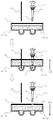
- Fig. 15 shows the details of the initial cleaning in the analysis workflow.
- the anode side cleaning layer 31 of the anode side buffer solution container 30 is inserted into the capillary head 13 and the electrode 115.
- the film 55 is inserted until a hole is made in the capillary head boss 14 portion. Thereafter, the anode side cleaning layer 31 is pulled out.
- the outer diameter of the capillary head boss 14 is thicker than the outer diameter of the capillary head tip 15, and the film 55 is in a state where an expansion hole 150 larger than the capillary head tip 15 is formed.
- FIG. 16 shows the details of the liquid contact state with the buffer in the analysis workflow.
- the sample introduction buffer layer 33 or the anode side electrophoresis buffer layer 32 of the anode side buffer solution container 30 is inserted into the capillary head 13 and the electrode 115.
- the insertion depth is made shallower than when inserted into the anode-side cleaning liquid layer 31.
- the through hole 151 is opened in the film 55, but the buffer solution adhering to the capillary head 13 falls within the buffer solution attachment range 155.
- the range of the swimming medium 26 attached to the capillary head 13 when connected to the electrophoresis medium container 20 is also connected to be equal.
- Fig. 17 shows details of cleaning in the analysis workflow.
- the anode-side cleaning layer 31 of the anode-side buffer container 30 after the initial cleaning once is inserted into the capillary head 13 and the electrode 115.
- the film 55 of the anode side cleaning layer 31 is in a state in which an expansion hole 150 is opened. Since the expansion hole 150 is thicker than the outer diameter of the capillary head tip 15, the capillary head tip 15 does not touch the film 55. Therefore, the portion of the buffer solution attachment range 155 attached to the capillary head tip 15 can be cleaned with the anode side cleaning solution 35 without touching the film 55. Further, since the insertion depth is also deep, it is possible to clean up to the cleaning range 156, and it is possible to clean all portions of the buffer solution adhesion range 155 adhering to the capillary head 13.
- two anode side cleaning layers 31 may be provided.
- the upper surface may be sealed with a notched rubber scepter instead of the film 55, and the solution adhering to the capillary head 13 may be wiped off. If the number of analyzes to be performed continuously is small, the amount of buffer mixed in the electrophoresis medium 26 is reduced. In that case, the cleaning operation itself becomes unnecessary.
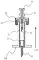
- FIG. 18 shows a diagram of an initial state, which is a series of movements of the electrophoresis medium 26 injection operation.
- the electrophoresis medium container 20 is set by being inserted into the guide 101 embedded in the sample tray 100.
- the plunger 61 of the liquid feeding mechanism 60 is disposed directly under the electrophoresis medium container 20, and the seal 22 in the electrophoresis medium container 20 can be moved by the movement of the plunger 61.
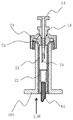
- FIG. 19 shows a state of the plunger 61 contact detection state, which is a series of movements of the electrophoresis medium 26 injection operation.
- the plunger 61 of the liquid feeding mechanism 60 is brought into contact with the seal 22 in the electrophoresis medium container 20, and the position thereof is detected.
- the stepping motor 62 of the liquid feeding mechanism 60 is driven with a weak driving current, and the stepping motor 62 is stepped out when it contacts the seal 22. Since it is desired to reduce the load on the seal 22, the drive current of the stepping motor 62 is adjusted so that the thrust of the plunger 61 at this time is about 10N.
- the contact of the plunger 61 is detected.
- the contact position of the plunger 61 it is possible to accurately grasp the amount of the electrophoresis medium 26 in the electrophoresis medium container 20, and use it for managing the amount of liquid fed and detecting leaks.
- the plunger 61 is excited with a current larger than the current at the time of driving and is held at a position in contact with the seal 22. It is desirable that the current value at the time of excitation is a current value that can hold the same thrust as the pressure generated when the electrophoresis medium 21 is fed.
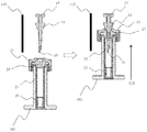
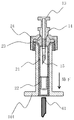
- FIG. 20 shows a state in which the capillary head 13 is connected, which is a series of movements of the electrophoresis medium 26 injection operation.
- the capillary head 13 and the electrophoresis medium container 20 are connected by the movement of the Z-axis drive body 90 of the auto sampler unit 150.
- the rubber cap 23 in the electrophoresis medium container 20 is penetrated and connected by the sharp capillary head tip 15. Since the plunger 61 of the liquid feeding mechanism 60 is mounted on the Z drive body 90 of the autosampler unit 150, the plunger 61 is connected while being in contact with the seal 22. Further, as described above, the capillary head boss 14 is connected while pressing the rubber plug 23 from above.
- the capillary head 13 is inserted into the electrophoresis medium container 20 while being sealed by the rubber plug 23.
- a volume change occurs in the electrophoresis medium container 20 and the pressure in the electrophoresis medium container 20 increases.
- the seal 22 is suppressed by the plunger 61, the seal 22 does not operate.
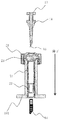
- FIG. 21 shows a diagram of the migration medium 26 injection state, which is a series of movements of the migration medium 26 injection operation.
- the plunger 61 is driven by the liquid feeding mechanism 60, thereby operating the seal 22 and feeding the liquid by changing the volume in the electrophoresis medium container 20.
- the inside of the electrophoresis medium container 20 becomes high pressure, and each component of the electrophoresis medium container 20 expands. Since the migration medium container 20 has low rigidity this time, the expansion amount is large and unstable. For this reason, the expansion of the electrophoresis medium container 20 greatly affects the sealing performance of the electrophoresis medium 26.
- the expansion of the syringe 21 is suppressed by the guide 101. Further, the expansion of the rubber plug 23 is suppressed by the capillary head 13. Furthermore, since the shape of the seal 22 is a concave shape, the seal 22 is more sealed when the seal 22 is expanded by internal pressure. By making the shape and strength of the seal 22 easier to expand than the syringe 21, the influence of the expansion of the syringe 21 can be reduced. Specifically, the thickness of the syringe 21 is set to 1 mm, the thickness of the seal 22 is set to about 0.6 mm, and a difference is provided in the expansion coefficient.
- the stepping motor 62 is driven by a driving current that provides a pressure necessary for liquid feeding, and the plunger 61 is driven.
- the pressure required for liquid feeding this time is 3 MPa, and in order to generate the pressure, the drive current of the stepping motor 62 is adjusted so that the thrust of the plunger 61 is 75N.
- the inside of the electrophoresis medium container 20 expands, but the stepping motor 62 steps out when the internal pressure increases by a necessary pressure.
- this defoliation is detected by the rotary encoder 63. Even after the step-out is detected, the stepping motor 62 continues to drive while stepping out.
- the plunger 61 Since the electrophoresis medium 26 is gradually fed through the capillary 11, the plunger 61 is gradually driven. Then, after detecting that the electrophoresis medium container 20 has fully expanded, the amount of the plunger 61 driven is detected by the rotary encoder 63, and the required amount of the electrophoresis medium 26 is sent to the capillary 11.
- the liquid feeding amount can be managed without being affected by the expansion of the electrophoresis medium container 20.
- FIG. 22 and 23 show details of the residual pressure removal operation in the electrophoresis medium container 20 as a series of movements of the electrophoresis medium 26 injection operation.
- the plunger 61 of the liquid feeding mechanism 60 is lowered as shown in FIG. 21 to release the contact with the seal 22.
- the pressure inside the electrophoresis medium container 20 is still increased.
- the seal 22 is pushed back by the pressure inside the electrophoresis medium container 20, and the residual pressure inside the electrophoresis medium container 20 is removed.
- FIG. 24 shows a detailed view of the capillary head 13 connection release operation, which is a series of movements of the electrophoresis medium 26 injection operation.
- the connection between the capillary head 13 and the electrophoresis medium container 20 is released by the movement of the Z-axis drive body 90 of the autosampler unit 150.
- the electrophoresis medium 26 is scattered when the capillary head 13 and the electrophoresis medium container 20 are disconnected.
- the electrophoresis medium 26 is fed to the capillary 11.
- a separate sensor may be provided when detecting contact of the plunger 61 during the liquid feeding operation.
- the spring When the plunger 61 comes into contact with the seal 22, the spring may be bent, and the detection plate may cut the sensor due to the bending.
- a contact type switch may be mounted.
- the residual pressure When removing the residual pressure during the liquid feeding operation, the residual pressure remains in the electrophoresis medium container 20 by the sliding resistance of the seal 22. Therefore, the residual pressure may be removed by fixing the plunger 61 and the seal 22 and forcibly lowering the seal 22. At this time, a mechanism for fixing the plunger 61 and the seal 22 is required, but the residual pressure due to the sliding resistance of the seal 22 can also be removed.
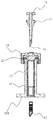
- FIG. 25 shows another form of the electrophoresis medium container 20.
- the bottom of the syringe 21 is sealed, and the electrophoresis medium container 20 having a rubber stopper 23 having the same function as the seal 22 is provided.
- the Z-axis driver 90 of the autosampler unit 150 By only moving the Z-axis driver 90 of the autosampler unit 150, the capillary head 13 is passed through the rubber plug 23 of the electrophoresis medium container 20, and the capillary head 13 is pushed further, thereby feeding the electrophoresis medium 26 to the capillary 11. Is also possible.
- the sliding resistance when moving for liquid feeding is larger than the force for penetrating the rubber plug 23 with the capillary head 11.
- the autosampler unit 150 may be divided on the anode side and the cathode side.
- the X-axis driver 95 for sample switching may be mounted not on the sample tray 100 but on the sampler base 80 and driven on the X-axis for each sample tray 100.
- the anode-side electrode 115 may be integrated with the capillary head 13. When the capillary head 13 is made of a material that can be electrically connected and falls to GND when the capillary head 13 is fixed, the electrode 115 itself becomes unnecessary.
- a plurality of electrophoresis medium containers 20 may be set. By setting a plurality, it is possible to increase the number of times that continuous RUN can be performed. Alternatively, the amount of the electrophoresis medium 26 enclosed in the electrophoresis medium container 20 may be varied according to the number of times of performing the continuous RUN. Moreover, in order to make the type of the electrophoresis medium container 20 one type, the electrophoresis medium container 20 for 1 RUN may be sealed in the electrophoresis medium container 20 and set for the number of times of performing the continuous RUN.
- a plurality of types of migration media 26 sealed in the migration media container 20 may be used. There are a plurality of types of migration media 26, and appropriate migration media 26 differ depending on the content of analysis. Therefore, the structure of the electrophoresis medium container 20 is the same, and various types of analysis can be handled by changing the type of the electrophoresis medium 26 enclosed therein. Management at that time is performed by a bar code attached to the electrophoresis medium container 20.
Landscapes
- Health & Medical Sciences (AREA)
- Life Sciences & Earth Sciences (AREA)
- Chemical & Material Sciences (AREA)
- Molecular Biology (AREA)
- Biochemistry (AREA)
- Electrochemistry (AREA)
- Physics & Mathematics (AREA)
- Analytical Chemistry (AREA)
- Chemical Kinetics & Catalysis (AREA)
- General Health & Medical Sciences (AREA)
- General Physics & Mathematics (AREA)
- Immunology (AREA)
- Pathology (AREA)
- Dispersion Chemistry (AREA)
- Automatic Analysis And Handling Materials Therefor (AREA)
- Sampling And Sample Adjustment (AREA)
- Investigating Or Analysing Biological Materials (AREA)
Abstract
Description
キャピラリと、
キャピラリの先端に設けられたキャピラリヘッドと、
電気泳動に用いる、泳動媒体が充填された泳動媒体充填容器と、
泳動媒体充填容器の側面を覆うガイド部材と、
泳動媒体充填容器に充填された泳動媒体を下方から封止するシール部材と、
シール部材を押圧するプランジャと、を備えている。
11:キャピラリ
12:検出部
13:キャピラリヘッド
14:キャピラリヘッドボス
15:キャピラリヘッド先端
16:ロードヘッタ
17:SUSパイプ
20:泳動媒体容器
21:シリンジ
22:シール
23:ゴム栓
24:キャップ
26:泳動媒体
27:空気
30:陽極側緩衝液容器
31:陽極側洗浄層
32:陽極側電気泳動用緩衝液層
33:陽極側サンプル導入用緩衝液層
35:陽極側洗浄液
36:陽極側電気泳動用緩衝液
37:陽極側サンプル導入用緩衝液
40:陰極側緩衝液容器
41:廃液層
42:陰極側洗浄層
43:陰極側電気泳動用緩衝液層
45:廃液受け液
46:陰極側洗浄液
47:陰極側電気泳動用緩衝液
50:サンプル容器
51:サンプル
55:フィルム
56:仕切り
60:送液機構
61:プランジャ
62:ステッピングモーター
63:ロータリーエンコーダー
64:原点センサ
65:ボールネジ
66:リニアガイド
67:駆動プーリ
68:受動プーリ
69:ベルト
70:送液機構ベース
71:スライダー
72:検知板
80:サンプラーベース
85:Y駆動体
90:Z駆動体
95:X駆動体
100:サンプルトレイ
101:ガイド
110:恒温槽ユニット
115:電極
120:恒温槽ドア
130:照射検出ユニット
150:オートサンプラーユニット
160:照射検出/恒温槽ユニット
200:分析ワークフローのチャート(各消耗品セット)
201:分析ワークフローのチャート(キャピラリの温調)
202:分析ワークフローのチャート(キャピラリの洗浄)
203:分析ワークフローのチャート(泳動媒体の送液)
204:分析ワークフローのチャート(サンプル導入)
205:分析ワークフローのチャート(電気泳動)
206:分析ワークフローのチャート(分析終了)
Claims (17)
- 電気泳動によって、キャピラリ内にサンプルを送液し、当該サンプルを光学検出する電気泳動装置において、
キャピラリと、
前記キャピラリの先端に設けられたキャピラリヘッドと、
電気泳動に用いる、泳動媒体が充填された泳動媒体充填容器と、
前記泳動媒体充填容器の側面を覆うガイド部材と、
前記泳動媒体充填容器に充填された泳動媒体を下方から封止するシール部材と、
前記シール部材を押圧するプランジャと、を備えたことを特徴とする、電気泳動装置。 - 請求項1において、
前記泳動媒体充填容器の上方は開口部となっており、当該開口部は弾性体により封止されていることを特徴とする、電気泳動装置。 - 請求項1において、
前記キャピラリヘッドの先端は、鋭角の角度を有していることを特徴とする、電気泳動装置。 - 請求項1において、
さらに、前記泳動媒体充填容器を保持する平板を有することを特徴とする、電気泳動装置。 - 請求項4において、
前記平板上には、さらに陽極側緩衝液容器、陰極側緩衝液容器、およびサンプル容器が載置されていることを特徴とする、電気泳動装置。 - 請求項5において、
前記平板を当該平板面と平行な第1方向へ駆動させる第1駆動部と、当該平板面と垂直方向である第2方向へ駆動させる第2駆動部とを有することを特徴とする、電気泳動装置。 - 請求項6において、
前記泳動媒体充填容器および前記陽極緩衝液容器は、前記第1方向に並んで配置されていることを特徴とする、電気泳動装置。 - 請求項6において、
前記陰極側緩衝液容器および前記サンプル容器は、前記第1方向に並んで配置されていることを特徴とする、電気泳動装置。 - 請求項8において、
前記陰極側緩衝液容器は、廃液層、陰極側洗浄層、および陰極側電気泳動用緩衝液層を備え、
廃液層、陰極側洗浄層、および陰極側電気泳動用緩衝液層は、この順に第1方向に仕切られて設けられており、
前記泳動媒体充填容器と前記廃液層は、前記平板面における前記第1方向と直交する第3方向に並んで配置されていることを特徴とする、電気泳動装置。 - 請求項6において、
前記サンプル容器を、前記平板面における前記第1方向と直交する第3方向に駆動する第3駆動部を有することを特徴とする、電気泳動装置。 - 請求項1において、
前記シール部材は前記泳動媒体充填容器よりも、膨張係数が大きいことを特徴とする、電気泳動装置。 - 請求項1において、
前記キャピラリヘッドが陽極側の電極と一体化されていることを特徴とする、電気泳動装置。 - 請求項1において、
前記プランジャが前記シール部材に接触した位置を検知する接触位置検知部を有することを特徴とする、電気泳動装置。 - 請求項7において、
前記陽極緩衝液容器は、陽極側洗浄層、陽極側電気泳動用緩衝液層、および陽極側サンプル導入用緩衝液層を備え、
陽極側洗浄層、陽極側電気泳動用緩衝液層、および陽極側サンプル導入用緩衝液層は、この順に第1方向に仕切られて設けられており、
前記陽極側サンプル導入用緩衝液層とサンプル容器は前記平板面における前記第1方向と直交する第3方向に並んで配置されていることを特徴とする、電気泳動装置。 - 請求項1において、
前記シール部材は、U字型の形状であることを特徴とする、電気泳動装置。 - キャピラリと、キャピラリの先端に設けられたキャピラリヘッドと、電気泳動に用いる、泳動媒体が充填された泳動媒体充填容器と、泳動媒体充填容器の側面を覆うガイド部材と、泳動媒体充填容器に充填された泳動媒体を下方から封止するシール部材と、シール部材を押圧するプランジャと、を備えた分析装置を用いた分析方法であって、
前記キャピラリヘッドを前記ポリマ充填容器の蓋を突き破る工程と、
前記シール部材を前記プランジャで押し込む時に、前記キャピラリヘッドで前記泳動媒体リマ充填容器の蓋部を押さえる工程を有することを特徴とする、電気泳動方法。 - 請求項16において、
前記プランジャからの前記シール部材への押圧力を解除してから、前記キャピラリヘッドをポリマ充填容器から抜く工程を有することを特徴とする電気泳動方法。
Priority Applications (9)
| Application Number | Priority Date | Filing Date | Title |
|---|---|---|---|
| US15/560,395 US10705046B2 (en) | 2015-03-27 | 2015-03-27 | Electrophoresis device and electrophoresis method |
| PCT/JP2015/059532 WO2016157272A1 (ja) | 2015-03-27 | 2015-03-27 | 電気泳動装置および電気泳動方法 |
| CN202010542681.XA CN111579623B (zh) | 2015-03-27 | 2015-03-27 | 电泳装置及电泳方法 |
| DE112015006171.1T DE112015006171B4 (de) | 2015-03-27 | 2015-03-27 | Elektrophoresevorrichtung und Elektrophoreseverfahren |
| GB1714281.1A GB2552904B (en) | 2015-03-27 | 2015-03-27 | Electophoresis device and electrophoresis method |
| JP2017508808A JP6391811B2 (ja) | 2015-03-27 | 2015-03-27 | 電気泳動装置および電気泳動方法 |
| CN201580073825.9A CN107209149B (zh) | 2015-03-27 | 2015-03-27 | 电泳装置及电泳方法 |
| US16/885,828 US11226307B2 (en) | 2015-03-27 | 2020-05-28 | Electrophoresis device and electrophoresis method |
| US17/533,317 US12196707B2 (en) | 2015-03-27 | 2021-11-23 | Electrophoresis method |
Applications Claiming Priority (1)
| Application Number | Priority Date | Filing Date | Title |
|---|---|---|---|
| PCT/JP2015/059532 WO2016157272A1 (ja) | 2015-03-27 | 2015-03-27 | 電気泳動装置および電気泳動方法 |
Related Child Applications (2)
| Application Number | Title | Priority Date | Filing Date |
|---|---|---|---|
| US15/560,395 A-371-Of-International US10705046B2 (en) | 2015-03-27 | 2015-03-27 | Electrophoresis device and electrophoresis method |
| US16/885,828 Division US11226307B2 (en) | 2015-03-27 | 2020-05-28 | Electrophoresis device and electrophoresis method |
Publications (1)
| Publication Number | Publication Date |
|---|---|
| WO2016157272A1 true WO2016157272A1 (ja) | 2016-10-06 |
Family
ID=57004025
Family Applications (1)
| Application Number | Title | Priority Date | Filing Date |
|---|---|---|---|
| PCT/JP2015/059532 Ceased WO2016157272A1 (ja) | 2015-03-27 | 2015-03-27 | 電気泳動装置および電気泳動方法 |
Country Status (6)
| Country | Link |
|---|---|
| US (3) | US10705046B2 (ja) |
| JP (1) | JP6391811B2 (ja) |
| CN (2) | CN107209149B (ja) |
| DE (1) | DE112015006171B4 (ja) |
| GB (1) | GB2552904B (ja) |
| WO (1) | WO2016157272A1 (ja) |
Cited By (4)
| Publication number | Priority date | Publication date | Assignee | Title |
|---|---|---|---|---|
| WO2019003330A1 (ja) * | 2017-06-28 | 2019-01-03 | 株式会社 日立ハイテクノロジーズ | 泳動媒体容器 |
| WO2019026133A1 (ja) * | 2017-07-31 | 2019-02-07 | 株式会社日立ハイテクノロジーズ | キャピラリ電気泳動装置 |
| WO2019065558A1 (ja) * | 2017-09-26 | 2019-04-04 | 株式会社日立ハイテクノロジーズ | キャピラリ電気泳動装置 |
| WO2023139711A1 (ja) * | 2022-01-20 | 2023-07-27 | 株式会社日立ハイテク | 電気泳動システム |
Families Citing this family (5)
| Publication number | Priority date | Publication date | Assignee | Title |
|---|---|---|---|---|
| CN107209149B (zh) * | 2015-03-27 | 2020-06-30 | 株式会社日立高新技术 | 电泳装置及电泳方法 |
| CN108027305B (zh) * | 2015-09-20 | 2022-03-01 | Dh科技发展私人贸易有限公司 | 小样本注射瓶管 |
| CN115190972B (zh) * | 2020-03-02 | 2024-07-26 | 株式会社日立高新技术 | 毛细管阵列单元以及电泳装置 |
| JP7289985B2 (ja) * | 2020-03-06 | 2023-06-12 | 株式会社日立ハイテク | 計測システム、および送液制御方法 |
| CN113203786B (zh) * | 2021-06-11 | 2023-03-31 | 南昌大学 | 毛细管电泳仪 |
Citations (2)
| Publication number | Priority date | Publication date | Assignee | Title |
|---|---|---|---|---|
| JP2003524747A (ja) * | 1997-06-30 | 2003-08-19 | スペクトルメディックス コーポレーション | 自動化平行キャピラリー電気泳動システム |
| JP2014021052A (ja) * | 2012-07-23 | 2014-02-03 | Hitachi High-Technologies Corp | 前処理・電気泳動用一体型カートリッジ、前処理一体型キャピラリ電気泳動装置及び前処理一体型キャピラリ電気泳動方法 |
Family Cites Families (30)
| Publication number | Priority date | Publication date | Assignee | Title |
|---|---|---|---|---|
| US3581956A (en) * | 1968-09-26 | 1971-06-01 | Hamilton Co | Syringe plunger head |
| US6001230A (en) * | 1988-04-29 | 1999-12-14 | Beckman Coulter, Inc. | Automated capillary electrophoresis apparatus |
| AU5745494A (en) * | 1992-12-14 | 1994-07-04 | Mallinckrodt Medical, Inc. | Pre-filled, sterilized syringe and method of making |
| US5635050A (en) | 1995-08-23 | 1997-06-03 | Beckman Instruments, Inc. | Electrophoretic system including means for replacing separation medium |
| US5695465A (en) * | 1995-07-24 | 1997-12-09 | Zhu; Jinyou | Syringe containing drug to be injected |
| US6365024B1 (en) | 1997-06-30 | 2002-04-02 | Spectrumedix Corporation | Motorized positioning apparatus having coaxial carrousels |
| US6027627A (en) * | 1997-06-30 | 2000-02-22 | Spectrumedix Corporation | Automated parallel capillary electrophoretic system |
| JP3896739B2 (ja) * | 1999-10-29 | 2007-03-22 | 株式会社日立製作所 | キャピラリー電気泳動装置 |
| JP3389547B2 (ja) * | 2000-02-28 | 2003-03-24 | 株式会社日立製作所 | 電気泳動装置 |
| US20030052074A1 (en) * | 2001-09-17 | 2003-03-20 | Chang Min Shuan | Closure for container for holding biological samples |
| DE102004047276B4 (de) | 2004-09-24 | 2006-11-30 | Siemens Ag | Selbsthaftende Elastomerschicht in feststoffisolierten Schalterpolen |
| JP4357399B2 (ja) * | 2004-10-08 | 2009-11-04 | 株式会社日立ハイテクノロジーズ | 電気泳動装置 |
| SE529693C2 (sv) * | 2005-03-04 | 2007-10-30 | Millipore Ab | Steril spruta |
| JP4375257B2 (ja) * | 2005-03-09 | 2009-12-02 | 株式会社島津製作所 | キャピラリープレートを用いた電気泳動方法 |
| JP4398399B2 (ja) * | 2005-04-05 | 2010-01-13 | 株式会社日立ハイテクノロジーズ | キャピラリ電気泳動装置、及びキャピラリ電気泳動方法 |
| JP2006119158A (ja) * | 2006-01-30 | 2006-05-11 | Hitachi High-Technologies Corp | 電気泳動装置、及び電気泳動方法 |
| EP1997888A4 (en) * | 2006-03-24 | 2010-07-28 | Toshiba Kk | NUCLEIC ACID DETECTION CASSETTE AND NUCLEIC ACID DETERGENT |
| JP4286269B2 (ja) * | 2006-06-05 | 2009-06-24 | 株式会社日立ハイテクノロジーズ | キャピラリ電気泳動装置 |
| JP4297922B2 (ja) | 2006-06-27 | 2009-07-15 | 株式会社日立ハイテクノロジーズ | キャピラリ電気泳動装置 |
| JP4893209B2 (ja) * | 2006-10-03 | 2012-03-07 | 株式会社島津製作所 | 電気泳動装置 |
| JP5049115B2 (ja) * | 2007-12-28 | 2012-10-17 | 株式会社日立ハイテクノロジーズ | キャピラリ電気泳動装置 |
| EP2270490B1 (en) * | 2009-06-25 | 2017-01-25 | Herbert Funke | Apparatus for high pressure proportionating, injecting and/or routing analyte sample solutions |
| JP5657361B2 (ja) * | 2010-12-06 | 2015-01-21 | 株式会社朝日Fr研究所 | シリンジ用部材、該シリンジ用部材を用いた医療用シリンジ、及び該シリンジ用部材の製造方法 |
| JP5320416B2 (ja) * | 2011-01-26 | 2013-10-23 | 株式会社日立ハイテクノロジーズ | 電気泳動装置,キャピラリアレイ、及びキャピラリユニット |
| JP5143264B2 (ja) * | 2011-09-06 | 2013-02-13 | 株式会社日立ハイテクノロジーズ | 溶液収納装置 |
| JP5391350B2 (ja) | 2013-04-15 | 2014-01-15 | 株式会社日立ハイテクノロジーズ | 電気泳動媒体用容器及び電気泳動装置の駆動方法 |
| GB2530446B (en) * | 2013-07-08 | 2018-06-13 | Hitachi High Tech Corp | Capillary electrophoresis device |
| WO2015037308A1 (ja) * | 2013-09-12 | 2015-03-19 | 株式会社日立ハイテクノロジーズ | 電気泳動媒体容器および電気泳動装置 |
| CN106255876A (zh) * | 2014-03-07 | 2016-12-21 | 生命技术公司 | 用于使用毛细管电泳进行测序的设备、系统和方法 |
| CN107209149B (zh) * | 2015-03-27 | 2020-06-30 | 株式会社日立高新技术 | 电泳装置及电泳方法 |
-
2015
- 2015-03-27 CN CN201580073825.9A patent/CN107209149B/zh active Active
- 2015-03-27 US US15/560,395 patent/US10705046B2/en active Active
- 2015-03-27 GB GB1714281.1A patent/GB2552904B/en active Active
- 2015-03-27 WO PCT/JP2015/059532 patent/WO2016157272A1/ja not_active Ceased
- 2015-03-27 CN CN202010542681.XA patent/CN111579623B/zh active Active
- 2015-03-27 JP JP2017508808A patent/JP6391811B2/ja active Active
- 2015-03-27 DE DE112015006171.1T patent/DE112015006171B4/de active Active
-
2020
- 2020-05-28 US US16/885,828 patent/US11226307B2/en active Active
-
2021
- 2021-11-23 US US17/533,317 patent/US12196707B2/en active Active
Patent Citations (2)
| Publication number | Priority date | Publication date | Assignee | Title |
|---|---|---|---|---|
| JP2003524747A (ja) * | 1997-06-30 | 2003-08-19 | スペクトルメディックス コーポレーション | 自動化平行キャピラリー電気泳動システム |
| JP2014021052A (ja) * | 2012-07-23 | 2014-02-03 | Hitachi High-Technologies Corp | 前処理・電気泳動用一体型カートリッジ、前処理一体型キャピラリ電気泳動装置及び前処理一体型キャピラリ電気泳動方法 |
Cited By (20)
| Publication number | Priority date | Publication date | Assignee | Title |
|---|---|---|---|---|
| JPWO2019003330A1 (ja) * | 2017-06-28 | 2020-04-16 | 株式会社日立ハイテク | 泳動媒体容器 |
| GB2577222B (en) * | 2017-06-28 | 2022-05-25 | Hitachi High Tech Corp | Electrophoretic medium container |
| US11243187B2 (en) | 2017-06-28 | 2022-02-08 | Hitachi High-Tech Corporation | Electrophoretic medium container |
| DE112017007534T5 (de) | 2017-06-28 | 2020-01-23 | Hitachi High-Technologies Corporation | Elektrophoresemediumbehälter |
| GB2577222A (en) * | 2017-06-28 | 2020-03-18 | Hitachi High Tech Corp | Electrophoretic medium container |
| WO2019003330A1 (ja) * | 2017-06-28 | 2019-01-03 | 株式会社 日立ハイテクノロジーズ | 泳動媒体容器 |
| CN110945350A (zh) * | 2017-07-31 | 2020-03-31 | 株式会社日立高新技术 | 毛细管电泳装置 |
| US11360047B2 (en) | 2017-07-31 | 2022-06-14 | Hitachi High-Technologies Corporation | Capillary electrophoresis device |
| GB2578984A (en) * | 2017-07-31 | 2020-06-03 | Hitachi High Tech Corp | Capillary electrophoresis device |
| JPWO2019026133A1 (ja) * | 2017-07-31 | 2020-07-02 | 株式会社日立ハイテク | キャピラリ電気泳動装置 |
| WO2019026133A1 (ja) * | 2017-07-31 | 2019-02-07 | 株式会社日立ハイテクノロジーズ | キャピラリ電気泳動装置 |
| GB2578984B (en) * | 2017-07-31 | 2022-02-16 | Hitachi High Tech Corp | Capillary electrophoresis device |
| WO2019065558A1 (ja) * | 2017-09-26 | 2019-04-04 | 株式会社日立ハイテクノロジーズ | キャピラリ電気泳動装置 |
| JPWO2019065558A1 (ja) * | 2017-09-26 | 2020-10-22 | 株式会社日立ハイテク | 電気泳動装置及び電気泳動方法 |
| GB2580818B (en) * | 2017-09-26 | 2022-05-04 | Hitachi High Tech Corp | Capillary electrophoresis apparatus |
| GB2580818A (en) * | 2017-09-26 | 2020-07-29 | Hitachi High Tech Corp | Capillary Electrophoretic apparatus |
| DE112018004282T5 (de) | 2017-09-26 | 2020-05-14 | Hitachi High-Technologies Corporation | Kapillarelektrophoresevorrichtung |
| WO2023139711A1 (ja) * | 2022-01-20 | 2023-07-27 | 株式会社日立ハイテク | 電気泳動システム |
| GB2630188A (en) * | 2022-01-20 | 2024-11-20 | Hitachi High Tech Corp | Electrophoresis system |
| JP7665800B2 (ja) | 2022-01-20 | 2025-04-21 | 株式会社日立ハイテク | 電気泳動システム |
Also Published As
| Publication number | Publication date |
|---|---|
| US20200292493A1 (en) | 2020-09-17 |
| GB201714281D0 (en) | 2017-10-18 |
| GB2552904B (en) | 2020-10-21 |
| US20180059055A1 (en) | 2018-03-01 |
| US11226307B2 (en) | 2022-01-18 |
| US12196707B2 (en) | 2025-01-14 |
| CN111579623B (zh) | 2022-11-25 |
| DE112015006171B4 (de) | 2024-03-28 |
| DE112015006171T5 (de) | 2017-11-02 |
| CN107209149B (zh) | 2020-06-30 |
| CN107209149A (zh) | 2017-09-26 |
| US10705046B2 (en) | 2020-07-07 |
| CN111579623A (zh) | 2020-08-25 |
| US20220082524A1 (en) | 2022-03-17 |
| JP6391811B2 (ja) | 2018-09-19 |
| GB2552904A (en) | 2018-02-14 |
| JPWO2016157272A1 (ja) | 2017-11-02 |
Similar Documents
| Publication | Publication Date | Title |
|---|---|---|
| JP6391811B2 (ja) | 電気泳動装置および電気泳動方法 | |
| US8961902B2 (en) | Method and apparatus for analyte processing | |
| US20160216235A1 (en) | Electrophoresis Medium Receptacle and Electrophoresis Apparatus | |
| US8257569B2 (en) | Capillary array unit and capillary electrophoresis apparatus | |
| JP4831232B2 (ja) | 電気泳動装置及び電気泳動方法 | |
| JP6770650B2 (ja) | キャピラリ電気泳動装置 | |
| EP4229296A1 (en) | Method and apparatus for controlling fluid volumes to achieve separation and pcr amplification | |
| JPWO2015005048A1 (ja) | キャピラリ電気泳動装置 | |
| JP4801007B2 (ja) | 電気泳動装置及びそれに用いられるポンプ機構 | |
| JP6047448B2 (ja) | キャピラリ電気泳動装置における分離媒体充填方法 | |
| CN109791123B (zh) | 驱动螺杆装置、送液机构以及送液方法 | |
| JP5039585B2 (ja) | キャピラリ電気泳動装置 | |
| GB2584263A (en) | Electrophoresis device and electrophoresis method | |
| JP6754497B2 (ja) | 泳動媒体容器 | |
| JP2014163714A (ja) | 蒸発防止膜 | |
| CN115053128B (zh) | 计测系统及送液控制方法 |
Legal Events
| Date | Code | Title | Description |
|---|---|---|---|
| 121 | Ep: the epo has been informed by wipo that ep was designated in this application |
Ref document number: 15887428 Country of ref document: EP Kind code of ref document: A1 |
|
| ENP | Entry into the national phase |
Ref document number: 2017508808 Country of ref document: JP Kind code of ref document: A |
|
| ENP | Entry into the national phase |
Ref document number: 201714281 Country of ref document: GB Kind code of ref document: A Free format text: PCT FILING DATE = 20150327 |
|
| WWE | Wipo information: entry into national phase |
Ref document number: 112015006171 Country of ref document: DE |
|
| WWE | Wipo information: entry into national phase |
Ref document number: 15560395 Country of ref document: US |
|
| 122 | Ep: pct application non-entry in european phase |
Ref document number: 15887428 Country of ref document: EP Kind code of ref document: A1 |