WO2016152382A1 - エンジン及びエンジン作業機 - Google Patents
エンジン及びエンジン作業機 Download PDFInfo
- Publication number
- WO2016152382A1 WO2016152382A1 PCT/JP2016/055838 JP2016055838W WO2016152382A1 WO 2016152382 A1 WO2016152382 A1 WO 2016152382A1 JP 2016055838 W JP2016055838 W JP 2016055838W WO 2016152382 A1 WO2016152382 A1 WO 2016152382A1
- Authority
- WO
- WIPO (PCT)
- Prior art keywords
- exhaust gas
- muffler
- engine
- cylinder
- cooling air
- Prior art date
- Legal status (The legal status is an assumption and is not a legal conclusion. Google has not performed a legal analysis and makes no representation as to the accuracy of the status listed.)
- Ceased
Links
Images




Classifications
-
- F—MECHANICAL ENGINEERING; LIGHTING; HEATING; WEAPONS; BLASTING
- F01—MACHINES OR ENGINES IN GENERAL; ENGINE PLANTS IN GENERAL; STEAM ENGINES
- F01P—COOLING OF MACHINES OR ENGINES IN GENERAL; COOLING OF INTERNAL-COMBUSTION ENGINES
- F01P1/00—Air cooling
- F01P1/02—Arrangements for cooling cylinders or cylinder heads, e.g. ducting cooling-air from its pressure source to cylinders or along cylinders
-
- F—MECHANICAL ENGINEERING; LIGHTING; HEATING; WEAPONS; BLASTING
- F02—COMBUSTION ENGINES; HOT-GAS OR COMBUSTION-PRODUCT ENGINE PLANTS
- F02B—INTERNAL-COMBUSTION PISTON ENGINES; COMBUSTION ENGINES IN GENERAL
- F02B63/00—Adaptations of engines for driving pumps, hand-held tools or electric generators; Portable combinations of engines with engine-driven devices
- F02B63/02—Adaptations of engines for driving pumps, hand-held tools or electric generators; Portable combinations of engines with engine-driven devices for hand-held tools
-
- F—MECHANICAL ENGINEERING; LIGHTING; HEATING; WEAPONS; BLASTING
- F01—MACHINES OR ENGINES IN GENERAL; ENGINE PLANTS IN GENERAL; STEAM ENGINES
- F01N—GAS-FLOW SILENCERS OR EXHAUST APPARATUS FOR MACHINES OR ENGINES IN GENERAL; GAS-FLOW SILENCERS OR EXHAUST APPARATUS FOR INTERNAL-COMBUSTION ENGINES
- F01N1/00—Silencing apparatus characterised by method of silencing
-
- F—MECHANICAL ENGINEERING; LIGHTING; HEATING; WEAPONS; BLASTING
- F01—MACHINES OR ENGINES IN GENERAL; ENGINE PLANTS IN GENERAL; STEAM ENGINES
- F01N—GAS-FLOW SILENCERS OR EXHAUST APPARATUS FOR MACHINES OR ENGINES IN GENERAL; GAS-FLOW SILENCERS OR EXHAUST APPARATUS FOR INTERNAL-COMBUSTION ENGINES
- F01N1/00—Silencing apparatus characterised by method of silencing
- F01N1/08—Silencing apparatus characterised by method of silencing by reducing exhaust energy by throttling or whirling
-
- F—MECHANICAL ENGINEERING; LIGHTING; HEATING; WEAPONS; BLASTING
- F01—MACHINES OR ENGINES IN GENERAL; ENGINE PLANTS IN GENERAL; STEAM ENGINES
- F01N—GAS-FLOW SILENCERS OR EXHAUST APPARATUS FOR MACHINES OR ENGINES IN GENERAL; GAS-FLOW SILENCERS OR EXHAUST APPARATUS FOR INTERNAL-COMBUSTION ENGINES
- F01N1/00—Silencing apparatus characterised by method of silencing
- F01N1/14—Silencing apparatus characterised by method of silencing by adding air to exhaust gases
-
- F—MECHANICAL ENGINEERING; LIGHTING; HEATING; WEAPONS; BLASTING
- F01—MACHINES OR ENGINES IN GENERAL; ENGINE PLANTS IN GENERAL; STEAM ENGINES
- F01N—GAS-FLOW SILENCERS OR EXHAUST APPARATUS FOR MACHINES OR ENGINES IN GENERAL; GAS-FLOW SILENCERS OR EXHAUST APPARATUS FOR INTERNAL-COMBUSTION ENGINES
- F01N13/00—Exhaust or silencing apparatus characterised by constructional features
- F01N13/08—Other arrangements or adaptations of exhaust conduits
- F01N13/082—Other arrangements or adaptations of exhaust conduits of tailpipe, e.g. with means for mixing air with exhaust for exhaust cooling, dilution or evacuation
-
- F—MECHANICAL ENGINEERING; LIGHTING; HEATING; WEAPONS; BLASTING
- F01—MACHINES OR ENGINES IN GENERAL; ENGINE PLANTS IN GENERAL; STEAM ENGINES
- F01P—COOLING OF MACHINES OR ENGINES IN GENERAL; COOLING OF INTERNAL-COMBUSTION ENGINES
- F01P1/00—Air cooling
- F01P1/06—Arrangements for cooling other engine or machine parts
-
- F—MECHANICAL ENGINEERING; LIGHTING; HEATING; WEAPONS; BLASTING
- F01—MACHINES OR ENGINES IN GENERAL; ENGINE PLANTS IN GENERAL; STEAM ENGINES
- F01P—COOLING OF MACHINES OR ENGINES IN GENERAL; COOLING OF INTERNAL-COMBUSTION ENGINES
- F01P5/00—Pumping cooling-air or liquid coolants
- F01P5/02—Pumping cooling-air; Arrangements of cooling-air pumps, e.g. fans or blowers
-
- F—MECHANICAL ENGINEERING; LIGHTING; HEATING; WEAPONS; BLASTING
- F02—COMBUSTION ENGINES; HOT-GAS OR COMBUSTION-PRODUCT ENGINE PLANTS
- F02B—INTERNAL-COMBUSTION PISTON ENGINES; COMBUSTION ENGINES IN GENERAL
- F02B63/00—Adaptations of engines for driving pumps, hand-held tools or electric generators; Portable combinations of engines with engine-driven devices
- F02B63/04—Adaptations of engines for driving pumps, hand-held tools or electric generators; Portable combinations of engines with engine-driven devices for electric generators
-
- F—MECHANICAL ENGINEERING; LIGHTING; HEATING; WEAPONS; BLASTING
- F02—COMBUSTION ENGINES; HOT-GAS OR COMBUSTION-PRODUCT ENGINE PLANTS
- F02B—INTERNAL-COMBUSTION PISTON ENGINES; COMBUSTION ENGINES IN GENERAL
- F02B75/00—Other engines
- F02B75/16—Engines characterised by number of cylinders, e.g. single-cylinder engines
-
- F—MECHANICAL ENGINEERING; LIGHTING; HEATING; WEAPONS; BLASTING
- F01—MACHINES OR ENGINES IN GENERAL; ENGINE PLANTS IN GENERAL; STEAM ENGINES
- F01N—GAS-FLOW SILENCERS OR EXHAUST APPARATUS FOR MACHINES OR ENGINES IN GENERAL; GAS-FLOW SILENCERS OR EXHAUST APPARATUS FOR INTERNAL-COMBUSTION ENGINES
- F01N2260/00—Exhaust treating devices having provisions not otherwise provided for
- F01N2260/02—Exhaust treating devices having provisions not otherwise provided for for cooling the device
- F01N2260/022—Exhaust treating devices having provisions not otherwise provided for for cooling the device using air
-
- F—MECHANICAL ENGINEERING; LIGHTING; HEATING; WEAPONS; BLASTING
- F01—MACHINES OR ENGINES IN GENERAL; ENGINE PLANTS IN GENERAL; STEAM ENGINES
- F01N—GAS-FLOW SILENCERS OR EXHAUST APPARATUS FOR MACHINES OR ENGINES IN GENERAL; GAS-FLOW SILENCERS OR EXHAUST APPARATUS FOR INTERNAL-COMBUSTION ENGINES
- F01N2260/00—Exhaust treating devices having provisions not otherwise provided for
- F01N2260/20—Exhaust treating devices having provisions not otherwise provided for for heat or sound protection, e.g. using a shield or specially shaped outer surface of exhaust device
-
- F—MECHANICAL ENGINEERING; LIGHTING; HEATING; WEAPONS; BLASTING
- F01—MACHINES OR ENGINES IN GENERAL; ENGINE PLANTS IN GENERAL; STEAM ENGINES
- F01N—GAS-FLOW SILENCERS OR EXHAUST APPARATUS FOR MACHINES OR ENGINES IN GENERAL; GAS-FLOW SILENCERS OR EXHAUST APPARATUS FOR INTERNAL-COMBUSTION ENGINES
- F01N2270/00—Mixing air with exhaust gases
- F01N2270/02—Mixing air with exhaust gases for cooling exhaust gases or the apparatus
-
- F—MECHANICAL ENGINEERING; LIGHTING; HEATING; WEAPONS; BLASTING
- F01—MACHINES OR ENGINES IN GENERAL; ENGINE PLANTS IN GENERAL; STEAM ENGINES
- F01N—GAS-FLOW SILENCERS OR EXHAUST APPARATUS FOR MACHINES OR ENGINES IN GENERAL; GAS-FLOW SILENCERS OR EXHAUST APPARATUS FOR INTERNAL-COMBUSTION ENGINES
- F01N2590/00—Exhaust or silencing apparatus adapted to particular use, e.g. for military applications, airplanes, submarines
- F01N2590/06—Exhaust or silencing apparatus adapted to particular use, e.g. for military applications, airplanes, submarines for hand-held tools or portables devices
-
- F—MECHANICAL ENGINEERING; LIGHTING; HEATING; WEAPONS; BLASTING
- F01—MACHINES OR ENGINES IN GENERAL; ENGINE PLANTS IN GENERAL; STEAM ENGINES
- F01P—COOLING OF MACHINES OR ENGINES IN GENERAL; COOLING OF INTERNAL-COMBUSTION ENGINES
- F01P1/00—Air cooling
- F01P1/02—Arrangements for cooling cylinders or cylinder heads, e.g. ducting cooling-air from its pressure source to cylinders or along cylinders
- F01P2001/023—Cooling cylinders
-
- F—MECHANICAL ENGINEERING; LIGHTING; HEATING; WEAPONS; BLASTING
- F01—MACHINES OR ENGINES IN GENERAL; ENGINE PLANTS IN GENERAL; STEAM ENGINES
- F01P—COOLING OF MACHINES OR ENGINES IN GENERAL; COOLING OF INTERNAL-COMBUSTION ENGINES
- F01P2060/00—Cooling circuits using auxiliaries
- F01P2060/16—Outlet manifold
Definitions
- the present invention mainly relates to an engine working machine such as a brush cutter, a blower, or a chain saw, and an engine exhaust gas cooling structure used as a power source for a generator or the like.
- the distance between the muffler and the muffler cover can be increased to increase the opening area of the exhaust outlet of the muffler cover.
- the present invention has been made in view of the above background, and an object thereof is to provide an engine and an engine working machine that can achieve a sufficient cooling effect of exhaust gas without increasing the distance between the muffler cover and the muffler. There is to do.
- Another object of the present invention is to provide an engine and an engine working machine that exhausts the exhaust gas outside the muffler cover after sufficiently reducing the exhaust gas temperature in the housing or cover of the engine.
- a cylinder having a plurality of fins on the outer periphery and forming a combustion chamber, a cooling fan that generates cooling air for cooling the cylinder, and a substantially rectangular parallelepiped muffler attached to the cylinder are provided.
- An exhaust gas outlet is provided in the muffler so as to exhaust the exhaust gas along the first wall surface of the muffler in a direction perpendicular to the axial direction of the cylinder, and the first exhaust gas passed through between the fins.
- the cooling air is configured to flow along the second wall surface located on the downstream side in the exhaust gas discharge direction when viewed from the first wall surface so as to collide with the exhaust gas.
- the first cooling air is mixed with the exhaust gas, so that the exhaust gas temperature can be greatly reduced.
- an exhaust gas outlet for determining the exhaust gas discharge direction is formed in the muffler, and the exhaust gas passage is shifted to the upstream side in the exhaust gas outflow direction on the first wall surface of the muffler. It was arranged.
- the distance between the exhaust gas outlet of the exhaust gas regulating member and the intersecting region can be increased, so that the mixing distance between the second cooling air and the exhaust gas can be increased, and the exhaust gas temperature can be further reduced.
- a muffler cover that covers the muffler and forms a muffler chamber is provided, and the muffler cover is formed with an opening for exhausting exhaust gas into the outside air.
- the gas crossing region was formed so as to be located inside the outer edge contour position of the muffler cover.
- the second cooling air that has passed between the fins is located on the upstream side in the exhaust gas discharge direction from the first wall surface and is not adjacent to the second wall surface. After flowing along the first wall, the first gas flows along the first wall surface, and is merged substantially in parallel with the exhaust gas from the upstream side in the exhaust gas outflow direction. Since the second cooling air is thus combined with the exhaust gas substantially in parallel from the upstream side in the exhaust gas outflow direction, an air flow layer is formed by the second cooling air between the exhaust gas and the muffler cover.
- the exhaust gas temperature can be reduced by mixing the second cooling air and the exhaust gas without bringing the exhaust gas into contact with the muffler cover.
- a crankshaft for extracting engine output is provided, a cooling fan is provided at one end of the crankshaft, and a muffler is disposed on the opposite side of the cylinder shaft as seen from the cooling fan.
- the first cooling air and the second cooling air were exhausted air after cooling the cylinder.
- the amount of air for cooling the cylinder is reduced and the cylinder temperature does not rise.
- the exhaust air of the cylinder cooling air is sufficiently low (for example, 100 ° C. or less) with respect to the exhaust gas temperature (for example, 400 ° C. to 500 ° C.), so that the effect of reducing the exhaust gas temperature can be sufficiently obtained.
- the muffler cover is provided with a shielding portion that changes the second cooling air flow from the flow along the third wall surface to the flow along the first wall surface.
- a cylinder having a plurality of fins on the outer peripheral portion to form a combustion chamber, a cooling fan that generates cooling air for cooling the cylinder, and a substantially rectangular parallelepiped muffler attached to the cylinder
- the muffler is arranged so that the center position of the muffler is offset in the normal direction with respect to the center position of the outer side of the radiating fin as viewed in the axial direction of the cylinder, and is opened by the aligned arrangement.
- the first cooling air which is the exhaust air after cooling the cylinder, is allowed to flow into the space, and the exhaust gas is discharged in the direction of colliding with the first cooling air along the first wall surface of the muffler located on the opposite side as seen from the cylinder.
- An exhaust gas outlet was provided.
- the muffler and the exhaust gas can be efficiently cooled by using the cooling air after cooling the cylinder.
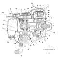
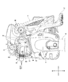
- FIG. 2 is a cross-sectional view taken along the line AA in FIG.
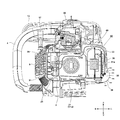
- FIG. 3 is a cross-sectional view taken along the line BB in FIG.
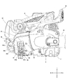
- FIG. 1 is a fan side (left side) side view of a chain saw 1 which is an example of an engine working machine.
- the chain saw 1 houses a small engine (described later) inside the engine cover 2.
- the engine working machine according to the present embodiment is configured so that the engine main body, the rotating mechanism portion, and the muffler portion that generate heat are entirely covered with a metal or synthetic resin cover.
- An engine (not shown) is fixed to an engine cover 2 made of synthetic resin.
- the engine cover 2 is provided with a flat guide bar 10 for guiding a saw chain that protrudes toward the front of the chain saw 1 (to the right in the drawing), and adjusts the output of the engine and the front handle 3 gripped by the operator.
- a rear handle (top handle) 4 having a trigger 6 is provided.
- a hand guard 13 is attached to the front side of the front handle 3 of the chain saw 1 so as to extend upward (upward in the figure).
- a fan cover 9 is provided on the left side surface of the engine cover 2 to cover a cooling fan 25 provided on the crankshaft 24 (described later in FIG. 2) of the engine.
- the fan cover 9 is provided with a plurality of wind windows 9a, 9b, 9c on the upper surface, rear side surface, lower surface and front surface.
- a recoil type starter (not shown) is provided inside the fan cover 9, and a starter handle 17 is disposed above the starter handle 17.
- a fuel tank (described later in FIG.
- FIG. 2 is a cross-sectional view taken along the line AA in FIG.
- the engine includes an engine main body 20 and auxiliaries such as a carburetor (described later) and a muffler 40, and various covers such as an engine cover 2, an air cleaner cover 8 (see FIG. 1), a fan cover 9, and a muffler cover 33. Consists of. The manufacturer can select whether to provide all or only a part of the covers for the engine body 20 according to the characteristics of the working equipment to be used.
- the engine body 20 is a two-cycle air-cooled engine, and is disposed so that the crankshaft 24 extends in the left-right direction, and the reciprocating direction of the piston 22 (the axis of the cylindrical surface of the cylinder) is the front-rear direction.
- a plurality of radiating fins 21a are formed on the outer periphery of the cylindrical cylinder 21, and the radiating fins 21a are exposed to the cooling air CA to cool the cylinder 21.
- the cylinder 21 is manufactured by integral molding of an aluminum alloy, and is substantially plate-shaped so that six cooling fins extend in a direction perpendicular to the axis of the cylinder 21 from the head portion where the spark plug 27 is disposed. Formed.
- An exhaust port 21b for discharging exhaust gas from the combustion chamber is provided on the side surface (here, the upper side) of the cylinder portion of the cylinder 21, and a muffler 40 is attached by a bolt 53 so as to be adjacent to the exhaust port 21b.
- the engine body 20 and the muffler 40 are in a form in which the opening of the exhaust port 21b of the cylinder 21 and the opening of the inflow side of the muffler 40 are directly joined without passing through a connection pipe line.
- a muffler gasket 49 is interposed between the cylinder 21 and the muffler 40 to enhance adhesion.
- a centrifugal clutch 31 is connected to one end side (right side) of the crankshaft 24, and power is transmitted to the sprocket 12 that rotates in conjunction with the clutch case 32 by the centrifugal clutch 31.
- a saw chain (not shown) is disposed on the outer peripheral side of the sprocket 12 and the guide bar 10, and the saw chain is rotationally driven by the rotation of the sprocket 12.
- the periphery of the sprocket 12 and the centrifugal clutch 31 is covered by the side cover 5.
- a cooling fan 25 that generates cooling air for cooling the cylinder 21 is provided on the other end side (left side) of the crankshaft 24.
- the cooling fan 25 is configured integrally with the magnet rotor, and is made of, for example, an aluminum alloy, and a magnet (not shown) for generating electric power in the ignition coil 26 is disposed on a part of the outer peripheral side.
- the cooling fan 25 also serves as a mounting base for a starting claw for driving the crankshaft 24 from the recoil starter 29.
- a fuel tank 18 is provided on the non-piston side (front side) of the crankcase 23. Fuel is supplied from the fuel tank 18, an air-fuel mixture is generated by a carburetor (not shown), and the air-fuel mixture is supplied from the intake port (not shown) to the inside of the cylinder 21 (combustion chamber). The supplied air-fuel mixture is ignited by a spark plug 27 at a predetermined timing. After combustion, when the piston 22 moves to the bottom dead center side and the exhaust port 21b is opened, the exhaust gas EX1 is discharged from the exhaust port 21b and flows into the muffler 40 as indicated by the dotted line.
- Cooling air CA is blown along the inner wall of the air guide cover 28.
- the cooling air CA is guided in the direction of the cylinder 21 through the air path formed by the wind guide cover 28 formed in a volute shape, and flows in the direction of the muffler 40 through between the radiating fins 21 a extending around the cylindrical portion of the cylinder 21. .
- the radiating fins 21a are sandwiched by the radiating fins 21a in the front-rear direction like the tip portion of the arrow of the cooling air CA. It flows into the space.
- the arrow in FIG. 2 shows a state in which the air flows between the heat dissipating fin (the first fin) closest to the spark plug among the heat dissipating fins 21a and the next heat dissipating fin (the second fin).
- the cooling air CA also flows between the 3rd to 6th fins of the cylinder, and also flows to the fins of the cylinder head portion behind the 1st fin.
- the cooling air flowing between the 1st to 4th fins is divided into upper and lower parts by the cylindrical portion of the cylinder 21 and collides with the wall surface of the muffler 40 on the cylinder side (here, the muffler gasket 49 is interposed).
- the muffler gasket 49 is disposed between the muffler 40 and the cylinder 21 and also functions as a heat shield and a wind guide plate. Cooling air flows into the muffler chamber at the upper and lower portions of the muffler 40.
- the carburetor and the muffler 40 (not shown) are arranged so as to be approximately 90 ° apart about the engine axis.
- the cooling fan 25 is arranged on one side (left side)
- the muffler 40 is arranged on the opposite side (right side)
- the cooling fan 25, the cylinder 21, and the muffler 40 are arranged in the axial direction of the crankshaft. It is arranged in a straight line.
- the muffler 40 is positioned on the leeward side of the cooling air CA after the cylinder 21 is cooled, so that the muffler 40 can be efficiently cooled.
- FIG. 3 is a cross-sectional view taken along the line BB of FIG.
- the exhaust gas EX1 of the muffler 40 flows as indicated by a dotted line, and is discharged downward along the first wall surface (the wall surface on the non-engine side) of the muffler 40 from the exhaust gas outlet 51a.
- the exhaust gas EX1 discharged from the exhaust gas outlet 51a is discharged to the outside mainly from the vicinity of the opening 35 (details will be described later) sandwiched between the ribs 34.
- the carburetor 30 is disposed on the upper side of the cylinder 21, and the muffler 40 and the carburetor 30 are disposed so as to be separated from each other by about 90 degrees when viewed from the axial direction of the cylinder 21.
- the cooling air CA shown in FIG. 2 is separated into an upper side and a lower side while flowing along the radiation fins 21a, and the lower cooling air CA1 is arranged along the second wall surface below the muffler 40 along the muffler cover 33. It flows toward the opening 35 vicinity. Therefore, the cooling fan CA1 merges with the exhaust gas EX1 by colliding and intersecting with the exhaust gas EX1 at right angles. Since the cooling air CA1 flows linearly from the lower part of the cooling fan 25 toward the cylinder 21 and from the bottom surface of the muffler 40 to the opening 35, the air path of the cooling air CA1 is smooth and smooth. Since it can form and there is little air path resistance, sufficient air volume can be ensured.
- the upper cooling air CA2 When the upper cooling air CA2 reaches the space between the radiating fins 21a stacked from the cooling fan 25, it passes through the upper side of the cylinder portion of the cylinder 21 and is guided to the upper space of the muffler chamber by the muffler gasket 49. Flows in the right direction through the upper wall surface (third wall surface), and then the flow direction is bent downward from the right direction along the inner wall surface of the muffler cover 33, so that the exhaust gas EX1 and the muffler cover 33 are located between the exhaust gas EX1 and the muffler cover 33. It flows toward the vicinity of the opening 35 through the space.
- the cooling air CA2 is gradually mixed with the exhaust gas EX1 while flowing along the outer wall surface (first wall surface) of the muffler 40 in the same direction as the exhaust gas EX1.
- This mixing reduces the temperature of the exhaust gas EX1.
- the exhaust gas is merged between the muffler cover 33 and the muffler 40 from the upstream side in the exhaust gas outflow direction so as to be substantially parallel to each other. Therefore, there is a layer of air flow by the second cooling air between the exhaust gas and the muffler cover.
- the exhaust gas temperature is obtained by mixing the second cooling air and the exhaust gas without bringing the exhaust gas into contact with the muffler cover. Can be reduced.
- the cooling air CA1 flowing below the muffler 40 is collided in a direction substantially orthogonal to the exhaust gas EX1 and the cooling air CA2, and the exhaust gas EX1 is further mixed with the cooling air CA1, thereby the muffler.
- the exhaust gas temperature discharged to the outside from the opening 35 of the cover 33 can be sufficiently reduced.
- the flow rate of the exhaust gas EX1 is sufficiently large with respect to the flow of the cooling air CA1, CA2.
- FIG. 4 is a view for explaining the relationship between the flow direction of the exhaust gas EX1 and the cooling air CA1, CA2.
- the first cooling air CA1 is guided so as to intersect (collision) with the exhaust gas EX1, has a first cooling air passage 37 surrounded by a thick frame, and an exhaust gas regulating member.
- a second cooling air passage 38 surrounded by a thick frame that guides the second cooling air CA2 from 50 to join the second cooling air CA2 substantially parallel to the exhaust gas EX1 from the upstream side in the exhaust gas outflow direction is formed.
- the extended area 60 of the exhaust gas outlet 51a from which the exhaust gas EX1 is discharged intersects with the extended area 61 (downstream flowing direction) of the first cooling air passage 37 at an intersecting area 63 indicated by hatching.
- it is shown in a two-dimensional view by a cross-sectional view, but in reality it is an intersection space.
- the present embodiment is characterized in that the intersection space including the intersection region 63 is located on the inner side (side closer to the cylinder 21) than the outer edge contour position of the muffler cover 33 (portions indicated by arrows 34a to 34e in FIG. 3). .
- the temperature of the exhaust gas EX1 is reduced by the cooling air CA1 in the space inside the opening 35, so that the temperature of the exhaust gas EX1 discharged into the outside air from the opening 35 is greatly reduced. It becomes.
- the temperature of the exhaust gas EX1 can be further lowered by further flowing the cooling air CA2 along the exhaust gas EX1 and mixing it with the exhaust gas EX1 in the extended region 62 of the cooling air path of the cooling air CA2. it can.
- the outside air is introduced as the cooling air CA3 into the muffler cover 33 through the opening 36 by the action of the downward flow of the cooling air CA2 on the downstream side of the exhaust gas outlet 51a. Merges with gas EX1.
- the cooling air CA1 and the exhaust gas EX1 are caused to collide with each other at an angle of approximately 90 degrees when viewed from the side, but the angle of collision is not limited to 90 degrees, and the exhaust gas EX1 and the cooling air CA1 are caused by the collision.
- the collision angle may be about 30 to 150 degrees.
- FIG. 5 is a view for explaining an offset arrangement of the muffler 40 with respect to the cylinder 21 of the chain saw 1 according to the embodiment of the present invention.
- the muffler 40 in order to form the first cooling air passage 37 for the cooling air CA ⁇ b> 1, the muffler 40 is arranged to be offset upward as indicated by an arrow 48 with respect to the heat radiation fin 21 a of the cylinder 21. That is, the muffler 40 is arranged so that the vertical center position of the muffler 40 is offset in the normal direction with respect to the center position of the outer side of the radiating fin 21a when viewed in the axial direction of the cylinder 21.
- the distance L from the lower end of the muffler 40 to the exhaust gas outlet 51a is more than half of the overall height H of the muffler 40 so that the distance from the exhaust gas outlet 51a to the opening 35 (see FIG. 4). Sufficient distance is secured. Further, as a result of offsetting the lower end position of the muffler 40 upward from the lower end of the radiating fin 21a of the cylinder 21, the distance from the exhaust gas outlet 51a to the outlet of the opening 35 can be further increased. It is suitable for reducing the temperature of EX1. On the other hand, the upper end position of the muffler 40 is sufficiently above the position of the radiation fins 21 a of the cylinder 21.
- the center line of the muffler 40 is offset to the upper side with respect to the center line of the outer side of the radiating fin 21a of the cylinder 21.
- the muffler 40 when viewed from the axial direction of the cylinder 21, the muffler 40 is arranged to be offset with respect to the cylinder 21, and the exhaust air after cooling the cylinder 21 to the space opened by the offset. Since the first cooling air CA1 is flown, it can collide with the exhaust gas EX1 with a large crossing angle.
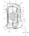
- FIG. 6 is a partially enlarged cross-sectional view of the muffler 40 of FIG.
- the muffler 40 is obtained by joining the inner housing 41 on the side close to the cylinder 21 and the opening of the outer housing 42 on the side far from the cylinder 21 together, and is connected to the rib 41a formed on the outer side.
- the outer edge portion 42a was crimped to form a substantially rectangular parallelepiped shape.
- the inner housing 41 and the outer housing 42 are joined via the partition plate 43, whereby the first expansion chamber 46 communicating with the exhaust port 21b of the cylinder 21 and the exhaust gas outlet side for exhausting the exhaust gas to the atmosphere.
- a second expansion chamber 47 is defined.
- the opening (suction port) of the first expansion chamber 46 is directly fixed to the cylinder 21 and is fixed by two bolts 53.
- a catalyst 44 for purifying exhaust gas is provided between the first expansion chamber 46 and the second expansion chamber 47, and the exhaust gas EX ⁇ b> 1 (see FIG. 3) is catalyst 44 provided at the opening of the partition plate 43. Flows from the first expansion chamber 46 to the second expansion chamber 47 side. Here, the temperature of the outer housing 42 is increased so that the high-temperature exhaust gas discharged from the catalyst 44 does not directly hit the outer housing 42.
- a catalyst cover 45 for suppression is provided.
- the partition plate 43 and the catalyst cover 45 can be manufactured, for example, by pressing a stainless plate.
- the exhaust gas expanded in the second expansion chamber 47 flows from the opening 47a of the second expansion chamber 47 to the exhaust gas passage 51 side, and is in a space covered by the muffler cover 33 from the exhaust gas outlet 51a of the exhaust gas passage 51 (muffler). It is discharged indoors.
- the exhaust gas passage 51 is a passage for determining the exhaust gas discharge direction formed by the exhaust gas regulating member 50 attached to the outer wall surface of the outer housing 42, and a tubular pipe line by the exhaust gas passage 51 extends downward.
- the exhaust gas outlet 51a which is the opening is formed on the lower side.
- the exhaust gas regulating member 50 is a separate member fixed to the outer housing 42 with a screw, and is provided by holding a wire mesh-like spark arrester 58 in the vicinity of the opening 47a of the outer housing 42.
- the exhaust gas passage 51 is formed by pressing a metal plate material.
- the exhaust gas EX1 is disposed along the wall surface of the outer housing 42 (exhaust gas regulating member 50) on the lower side (with the axial direction of the cylinder 21. Flows in the orthogonal direction).
- the exhaust gas discharged into the muffler chamber is discharged into the atmosphere from the opening 35 sandwiched between the ribs 34 at the front and rear.
- the rib 34 is formed to extend in a direction substantially parallel to the exhaust gas EX1 discharge direction.
- a space is provided between the muffler cover 33 and the muffler 40 so that the radiant heat of the muffler 40 is not easily transmitted to the muffler cover 33 made of synthetic resin.
- a muffler gasket 49 is provided.
- the muffler gasket 49 is, for example, a graphite sheet, and is interposed to improve the adhesion between the muffler 40 and the exhaust port 21b of the cylinder 21.
- the muffler gasket 49 not only functions as a gasket, but also serves as a heat shield plate to prevent the heat of the muffler 40 from being transmitted to the cylinder 21 side, and to guide the cooling air in a predetermined direction. Also used as.
- an opening 36 serving as a wind window is provided in the vicinity of the exhaust gas outlet 51a of the muffler cover 33.
- the opening 36 is provided adjacent to the large opening 35 serving as an outlet for the exhaust gas, and is provided to improve heat dissipation at the time of stopping and to suck outside air having a low temperature by the flow of the cooling air CA2. .
- FIG. 7 is a right side view of the chain saw 1.
- An opening 35 serving as an outlet for the exhaust gas EX1 to the atmosphere is formed on the side surface of the muffler cover 33, and the exhaust gas EX1 flowing out from the exhaust gas outlet 51a is discharged downward as indicated by an arrow.
- An opening 35 is formed between the two ribs 34, and a substantially rectangular opening 36 is formed above an imaginary line connecting the vicinity of the upper ends of the two ribs 34. Between the opening 35 and the opening 36, a beam 36a extending in the lateral direction is formed in order to increase the strength of the muffler cover 33.
- the beam 35a that extends obliquely is provided also in the opening 35, if the flow of the exhaust gas EX1 is not disturbed, it can be arbitrarily set at which position and how the beam 35a is provided.
- the exhaust gas EX1 is discharged substantially downward from the opening 35 of the muffler cover 33.
- the cooling air flows CA2 and CA3 flowing so as to cover the exhaust gas EX1 from the top to the bottom (FIG. 3). 4), and then intersects with the cooling air CA1 (see FIG. 3) flowing from the left to the right in the horizontal direction on the lower side of the muffler 40.
- the flow direction of the exhaust gas EX1 basically does not change in the downward direction even when mixed with the cooling air CA1, CA2, CA3.
- the exhaust gas EX1 is diffused and the cooling air CA1, CA2, CA3 having a sufficiently low temperature can be mixed with the exhaust gas EX1, so that the exhaust gas EX1 is discharged to the outside of the muffler cover 33.
- the temperature at the time can be greatly reduced.
- FIG. 8 is a right side view of the chain saw 1 with the muffler cover 33 removed.
- An exhaust gas passage 51 of the muffler 40 is formed in an exhaust gas regulating member 50 that is fixed to the muffler 40 with three screws 54.
- Most of the wall surface (first wall surface) of the muffler 40 on the side opposite to the engine is covered with the exhaust gas restriction member 50, but not only the size of the exhaust gas restriction member 50 but also the presence or absence of its specifications is arbitrary.
- the black thick line 51b around the exhaust gas EX1 in the discharge direction is an extension of the wall surface of the exhaust gas passage 51, and the exhaust gas EX1 is released while gradually diffusing mainly in the extension region between the thick lines.
- the discharge direction of the exhaust gas EX1 is slightly downward but slightly oblique to the rear side. Since the exhaust gas EX1 and the cooling air CA1 intersect in the region inside the outline 35b shown by the dotted line of the opening 35 of the muffler cover 33, when the exhaust gas EX1 is discharged to the outside of the muffler cover 33, the exhaust gas The temperature of EX1 can be greatly reduced. Furthermore, since a further opening 36 (see FIG. 7) is provided above the opening 35 of the muffler cover 33, room temperature air that has not been heated by the engine body 20 or the muffler 40 is passed through the opening 36 from the outside of the muffler cover 33. Can be supplied inside.
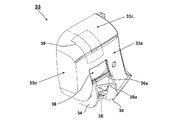
- FIG. 9 is a perspective view showing the appearance of the muffler cover 33.
- the muffler cover 33 has a right side surface 33a, a front side surface, an upper surface 33c, a rear side surface 33d, and a rear surface, and only two openings 35 and 36 are formed. If comprised in this way, the cooling air CA1 and CA2 which flowed into the muffler chamber will be discharged
- the cooling air CA2 is changed by the inner wall portion (shielding portion 39) of the portion indicated by the dotted line on the upper surface 33c of the muffler cover 33 from the horizontal direction from the left to the right and downward, so that the exhaust gas EX1
- the exhaust gas EX1 can be flowed substantially parallel to be combined with the exhaust gas EX1.
- an air flow layer having a low temperature can be formed between the exhaust gas EX1 and the muffler cover 33.
- the muffler cover 33 can be effectively protected from the high temperature of the muffler 40.
- the heat transfer to the muffler cover 33 is reduced in addition to the improvement of the cooling effect of the muffler 40, the distance between the muffler 40 and the muffler cover 33 can be reduced to reduce the size of the muffler cover 33. it can.
- the muffler cover 33 shown in FIG. 9 has a large exhaust gas temperature lowering effect when the engine is operating, but the flow of the cooling air CA1 and CA2 stops when the engine is stopped, so the muffler cover 33 is radiated by the heated muffler 40. Will heat up. Therefore, a muffler cover 83 is formed with a plurality of wind windows in the same manner as the muffler cover widely used in current engine working machines. An air window 91 is formed on the upper surface of the muffler cover 83, an air window 94 is formed on the right side surface, and air windows 95 and 96 are formed on the rear side surface.
- the depression 92 on the upper surface is a depression having the same shape as that of the wind window 91 adjacent to the front and rear, but the inside and the non-penetration are prevented from passing air.
- the dent 93 on the right side surface has the same shape as the front and rear adjacent wind windows 94, but is prevented from penetrating the inside.
- the ribs 84 and the openings 85 and 86 are formed in substantially the same shape as the ribs 34 and the openings 35 and 36 in the first embodiment. With this configuration, a muffler cover with good heat dissipation can be realized while maintaining the function of the shielding unit 39 shown in FIG.
- the wind shielding plate which consists of another member inside the part (for example, the part of the shielding part 39 in FIG. 9) corresponding to 93 and 94, A wind guide plate may be provided.
- a slightly thicker aluminum foil may be attached to the muffler cover 83 at the shielding portion 39.
- the cooling air CA ⁇ b> 2 that has passed through between the radiating fins 21 a of the cylinder 21 and has been diverted upwards of the muffler 40 has a wall portion (in the vicinity of the arrow 97) and a depression 92. 3 and FIG. 7 as described with reference to FIGS. 3 to 7, the temperature of the exhaust gas EX1 during the operation of the engine is not impaired. Also in this modification, since the distance between the exhaust gas outlet of the exhaust gas regulating member and the intersecting region can be increased, the mixing distance between the second cooling air and the exhaust gas can be increased, and the exhaust gas temperature can be sufficiently reduced.
- the exhaust gas after mixing with the first cooling air can be discharged outside the muffler cover without being brought into contact with the exhaust outlet portion of the muffler cover. Furthermore, since it is not necessary to take out part of the cooling air from the cooling fan and form an air path different from that of the cylinder, an inexpensive and compact structure can be achieved. At this time, by extracting a part of the cooling air, the air volume for cooling the cylinder is reduced, and the cylinder temperature does not rise.
- the structure of the engine has been described using a chain saw as an example of the engine working machine.
- the engine working machine is not only an engine for a chain saw, but also other engines such as a brush cutter, a hedge trimmer, and a cutter.
- the present invention can be similarly applied to a working machine, a generator, and an engine as a small power source.
- the engine main body can be similarly applied not only to a 2-cycle engine but also to a 4-cycle engine, and various types of mufflers can be used according to work equipment.
Landscapes
- Engineering & Computer Science (AREA)
- Chemical & Material Sciences (AREA)
- Combustion & Propulsion (AREA)
- Mechanical Engineering (AREA)
- General Engineering & Computer Science (AREA)
- Exhaust Silencers (AREA)
- Exhaust Gas After Treatment (AREA)
Abstract
Description
Claims (9)
- 外周部に複数のフィンを有し燃焼室を形成するシリンダと、前記シリンダを冷却する冷却風を生成する冷却ファンと、前記シリンダに取り付けられる略直方体状のマフラーを有するエンジンであって、排気ガスを前記マフラーの第1の壁面に沿って前記シリンダの軸方向と直交方向に排出するように前記マフラーに排気ガス出口を設け、前記フィンの間を通過した第1の冷却風を、前記第1の壁面からみて前記排気ガスの排出方向下流側に位置する第2の壁面に沿って流して前記排気ガスと合流させることを特徴とするエンジン。
- 前記マフラーに前記排気ガス出口を有し前記排気ガスの排出方向を決定する排気ガス通路を形成し、前記マフラーの第1の壁面上において、前記排気ガス通路を排気ガス流出方向の上流側に片寄せして配置したことを特徴とする請求項1に記載のエンジン。
- 前記マフラーを覆ってマフラー室を形成するマフラーカバーを設け、前記マフラーカバーには前記排気ガスを外気中に排出するための開口が形成され、前記第1の冷却風と前記排気ガスの交差領域が、前記マフラーカバーの外縁輪郭位置よりも内側に位置するよう形成したことを特徴とする請求項1又は2に記載のエンジン。
- 前記マフラーカバーの前記開口の縁部の一部に、前記排気ガスの排出方向と平行方向に延びるように前記排気ガスを案内するためのリブを設けたことを特徴とする請求項3に記載のエンジン。
- 前記フィンの間を通過した第2の冷却風を、前記第1の壁面から前記排気ガスの排出方向上流側に位置し前記第2の壁面と隣接しない第3の壁面に沿って流した後に前記第1の壁面に沿って流して、前記排気ガスの流出方向上流側から前記排気ガスと略平行に合流させることを特徴とする請求項3又は4に記載のエンジン。
- 前記エンジンの出力を取り出すクランク軸を有し、前記クランク軸の一端に前記冷却ファンを設け、前記冷却ファンからみて前記シリンダの軸に対して反対側に前記マフラーを配置し、前記第1の冷却風と前記第2の冷却風は、前記シリンダを冷却した後の排風であることを特徴とする請求項5に記載のエンジン。
- 前記マフラーカバーに、前記第2の冷却風を前記第3の壁面に沿った流れから前記第1の壁面にそった流れに変針させる遮蔽部を設けたことを特徴とする請求項6に記載のエンジン。
- 外周部に複数のフィンを有し燃焼室を形成するシリンダと、前記シリンダを冷却する冷却風を生成する冷却ファンと、前記シリンダに取り付けられる略直方体状のマフラーを有するエンジンであって、前記シリンダの軸線方向にみて前記フィンの外辺の中心位置に対して前記マフラーの中心位置が法線方向にオフセットするように前記マフラーを片寄せ配置し、前記片寄せ配置により開いた空間に前記シリンダを冷却した後の排風たる第1の冷却風を流し、前記シリンダからみて反対側に位置する前記マフラーの第1の壁面に沿って排気ガスを前記第1の冷却風に衝突させる方向に排出させる排気ガス出口を設けたことを特徴とするエンジン。
- 請求項1から8のいずれか一項に記載のエンジンを用いて作業機器を駆動させることを特徴とするエンジン作業機。
Priority Applications (4)
| Application Number | Priority Date | Filing Date | Title |
|---|---|---|---|
| CN201680007072.6A CN107208525B (zh) | 2015-03-25 | 2016-02-26 | 发动机及发动机式作业机 |
| JP2017507634A JP6260738B2 (ja) | 2015-03-25 | 2016-02-26 | エンジン及びエンジン作業機 |
| DE112016000471.0T DE112016000471T5 (de) | 2015-03-25 | 2016-02-26 | Motor und motorbetriebene Arbeitsmaschine |
| US15/547,518 US10280827B2 (en) | 2015-03-25 | 2016-02-26 | Engine and engine-driven working machine |
Applications Claiming Priority (2)
| Application Number | Priority Date | Filing Date | Title |
|---|---|---|---|
| JP2015-063511 | 2015-03-25 | ||
| JP2015063511 | 2015-03-25 |
Publications (1)
| Publication Number | Publication Date |
|---|---|
| WO2016152382A1 true WO2016152382A1 (ja) | 2016-09-29 |
Family
ID=56978326
Family Applications (1)
| Application Number | Title | Priority Date | Filing Date |
|---|---|---|---|
| PCT/JP2016/055838 Ceased WO2016152382A1 (ja) | 2015-03-25 | 2016-02-26 | エンジン及びエンジン作業機 |
Country Status (5)
| Country | Link |
|---|---|
| US (1) | US10280827B2 (ja) |
| JP (1) | JP6260738B2 (ja) |
| CN (1) | CN107208525B (ja) |
| DE (1) | DE112016000471T5 (ja) |
| WO (1) | WO2016152382A1 (ja) |
Cited By (2)
| Publication number | Priority date | Publication date | Assignee | Title |
|---|---|---|---|---|
| WO2018155072A1 (ja) * | 2017-02-23 | 2018-08-30 | 工機ホールディングス株式会社 | エンジン作業機 |
| JP2023105830A (ja) * | 2022-01-20 | 2023-08-01 | 株式会社やまびこ | 動力作業機 |
Families Citing this family (4)
| Publication number | Priority date | Publication date | Assignee | Title |
|---|---|---|---|---|
| JP6916049B2 (ja) * | 2017-06-22 | 2021-08-11 | 株式会社ミクニ | 汎用エンジン |
| WO2019187083A1 (ja) * | 2018-03-30 | 2019-10-03 | 本田技研工業株式会社 | 汎用エンジン |
| US11530636B2 (en) * | 2020-05-06 | 2022-12-20 | Kohler Co. | Engine exhaust heat management system |
| CN115853625A (zh) * | 2022-12-26 | 2023-03-28 | 隆鑫通用动力股份有限公司 | 风冷型通用发动机 |
Citations (2)
| Publication number | Priority date | Publication date | Assignee | Title |
|---|---|---|---|---|
| JPS5973525U (ja) * | 1982-11-10 | 1984-05-18 | 本田技研工業株式会社 | 発動発電機の冷却装置 |
| JP2000018033A (ja) * | 1998-06-30 | 2000-01-18 | Shin Daiwa Kogyo Co Ltd | エンジンの排気構造 |
Family Cites Families (4)
| Publication number | Priority date | Publication date | Assignee | Title |
|---|---|---|---|---|
| JPS5973525A (ja) | 1982-10-20 | 1984-04-25 | Sanraku Inc | 新規なラムノ−スホモポリマ−及びそれを有効成分とする抗腫瘍剤 |
| JP5699653B2 (ja) * | 2010-03-08 | 2015-04-15 | コベルコ建機株式会社 | 建設機械の冷却構造 |
| JP5915924B2 (ja) * | 2011-09-21 | 2016-05-11 | 日立工機株式会社 | エンジン及びエンジン作業機 |
| JP2013213414A (ja) | 2012-03-31 | 2013-10-17 | Hitachi Koki Co Ltd | エンジン作業機 |
-
2016
- 2016-02-26 DE DE112016000471.0T patent/DE112016000471T5/de not_active Withdrawn
- 2016-02-26 CN CN201680007072.6A patent/CN107208525B/zh not_active Expired - Fee Related
- 2016-02-26 WO PCT/JP2016/055838 patent/WO2016152382A1/ja not_active Ceased
- 2016-02-26 US US15/547,518 patent/US10280827B2/en active Active
- 2016-02-26 JP JP2017507634A patent/JP6260738B2/ja not_active Expired - Fee Related
Patent Citations (2)
| Publication number | Priority date | Publication date | Assignee | Title |
|---|---|---|---|---|
| JPS5973525U (ja) * | 1982-11-10 | 1984-05-18 | 本田技研工業株式会社 | 発動発電機の冷却装置 |
| JP2000018033A (ja) * | 1998-06-30 | 2000-01-18 | Shin Daiwa Kogyo Co Ltd | エンジンの排気構造 |
Cited By (5)
| Publication number | Priority date | Publication date | Assignee | Title |
|---|---|---|---|---|
| WO2018155072A1 (ja) * | 2017-02-23 | 2018-08-30 | 工機ホールディングス株式会社 | エンジン作業機 |
| JPWO2018155072A1 (ja) * | 2017-02-23 | 2019-07-04 | 工機ホールディングス株式会社 | エンジン作業機 |
| JP2023105830A (ja) * | 2022-01-20 | 2023-08-01 | 株式会社やまびこ | 動力作業機 |
| US12337456B2 (en) | 2022-01-20 | 2025-06-24 | Yamabiko Corporation | Power working machine |
| JP7759265B2 (ja) | 2022-01-20 | 2025-10-23 | 株式会社やまびこ | 動力作業機 |
Also Published As
| Publication number | Publication date |
|---|---|
| CN107208525A (zh) | 2017-09-26 |
| DE112016000471T5 (de) | 2017-10-12 |
| US20180016964A1 (en) | 2018-01-18 |
| JPWO2016152382A1 (ja) | 2017-07-20 |
| US10280827B2 (en) | 2019-05-07 |
| JP6260738B2 (ja) | 2018-01-17 |
| CN107208525B (zh) | 2020-06-19 |
Similar Documents
| Publication | Publication Date | Title |
|---|---|---|
| JP6260738B2 (ja) | エンジン及びエンジン作業機 | |
| JP6232984B2 (ja) | 空冷エンジンおよびエンジン作業機 | |
| JP5915485B2 (ja) | エンジン作業機 | |
| US20140216370A1 (en) | Engine and engine-operated working machine | |
| CN107208510B (zh) | 发动机及发动机式作业机 | |
| US9249715B2 (en) | Air cooled engine and engine-powered work tool | |
| WO2017130660A1 (ja) | エンジン及びエンジン作業機 | |
| JP5622536B2 (ja) | 空冷エンジンの冷却構造 | |
| JP2017133490A (ja) | エンジン及びエンジン作業機 | |
| JP6190603B2 (ja) | マフラ装置および携帯型作業機 | |
| JP6696621B2 (ja) | エンジン作業機 | |
| CN111148891B (zh) | 通用发动机 | |
| JP6572678B2 (ja) | エンジン及びエンジン作業機 | |
| JP5527140B2 (ja) | エンジンおよびそれを備えたエンジン作業機 | |
| JP2013068141A (ja) | エンジン及びエンジン作業機 | |
| WO2016031717A1 (ja) | エンジン作業機 | |
| CN111075549B (zh) | 通用发动机 | |
| JP2013189949A (ja) | エンジンおよびエンジン作業機 | |
| JP2016223353A (ja) | チェンソー |
Legal Events
| Date | Code | Title | Description |
|---|---|---|---|
| 121 | Ep: the epo has been informed by wipo that ep was designated in this application |
Ref document number: 16768285 Country of ref document: EP Kind code of ref document: A1 |
|
| ENP | Entry into the national phase |
Ref document number: 2017507634 Country of ref document: JP Kind code of ref document: A |
|
| WWE | Wipo information: entry into national phase |
Ref document number: 15547518 Country of ref document: US |
|
| WWE | Wipo information: entry into national phase |
Ref document number: 112016000471 Country of ref document: DE |
|
| 122 | Ep: pct application non-entry in european phase |
Ref document number: 16768285 Country of ref document: EP Kind code of ref document: A1 |