WO2016152224A1 - Actionneur piézoélectrique et pièce d'horlogerie électronique - Google Patents
Actionneur piézoélectrique et pièce d'horlogerie électronique Download PDFInfo
- Publication number
- WO2016152224A1 WO2016152224A1 PCT/JP2016/051746 JP2016051746W WO2016152224A1 WO 2016152224 A1 WO2016152224 A1 WO 2016152224A1 JP 2016051746 W JP2016051746 W JP 2016051746W WO 2016152224 A1 WO2016152224 A1 WO 2016152224A1
- Authority
- WO
- WIPO (PCT)
- Prior art keywords
- piezoelectric actuator
- piezoelectric
- elastic member
- voltage
- transmission
- Prior art date
Links
- 230000005540 biological transmission Effects 0.000 claims abstract description 116
- 238000006073 displacement reaction Methods 0.000 claims description 36
- 238000009434 installation Methods 0.000 abstract description 5
- 230000033001 locomotion Effects 0.000 description 42
- 230000007246 mechanism Effects 0.000 description 13
- 239000012790 adhesive layer Substances 0.000 description 11
- 238000000034 method Methods 0.000 description 11
- 239000000758 substrate Substances 0.000 description 6
- 238000005452 bending Methods 0.000 description 5
- 238000010586 diagram Methods 0.000 description 5
- 230000000694 effects Effects 0.000 description 5
- XEEYBQQBJWHFJM-UHFFFAOYSA-N Iron Chemical compound [Fe] XEEYBQQBJWHFJM-UHFFFAOYSA-N 0.000 description 4
- 230000008602 contraction Effects 0.000 description 4
- 230000005484 gravity Effects 0.000 description 4
- 239000000463 material Substances 0.000 description 4
- 230000004048 modification Effects 0.000 description 4
- 238000012986 modification Methods 0.000 description 4
- 230000001154 acute effect Effects 0.000 description 2
- 230000015572 biosynthetic process Effects 0.000 description 2
- 238000004891 communication Methods 0.000 description 2
- 229910052742 iron Inorganic materials 0.000 description 2
- 238000003825 pressing Methods 0.000 description 2
- 239000000853 adhesive Substances 0.000 description 1
- 230000001070 adhesive effect Effects 0.000 description 1
- 239000000919 ceramic Substances 0.000 description 1
- 239000010410 layer Substances 0.000 description 1
- 238000004519 manufacturing process Methods 0.000 description 1
- 230000008569 process Effects 0.000 description 1
- 230000004044 response Effects 0.000 description 1
- 239000007787 solid Substances 0.000 description 1
- 230000009466 transformation Effects 0.000 description 1
- 238000003466 welding Methods 0.000 description 1
Images


Classifications
-
- H—ELECTRICITY
- H02—GENERATION; CONVERSION OR DISTRIBUTION OF ELECTRIC POWER
- H02N—ELECTRIC MACHINES NOT OTHERWISE PROVIDED FOR
- H02N2/00—Electric machines in general using piezoelectric effect, electrostriction or magnetostriction
Definitions
- the present invention relates to a piezoelectric actuator and an electronic timepiece.
- a piezoelectric actuator including a displacement element (piezoelectric element) that expands and contracts when a voltage is applied.
- the piezoelectric actuator for example, causes mechanical resonance by applying a predetermined voltage to the piezoelectric element, and the transmission unit (columnar protrusion) operates so as to draw an elliptical orbit by this vibration. And the operation
- Japanese Patent Application Laid-Open No. 2009-71903 discloses a configuration including a pressurizing unit that applies pressure using a coil spring.
- the piezoelectric element has a resonance peak when a voltage having a predetermined frequency is applied. For this reason, in order to efficiently resonate the piezoelectric element, it is necessary to adjust the driving frequency when applying a voltage to the piezoelectric element to a frequency band where the resonance reaches a peak.
- a spring such as a coil spring is brought into contact with the piezoelectric actuator and the piezoelectric actuator is pressed by a spring force as in the conventional piezoelectric actuator described in Patent Document 1
- the spring comes into contact with the piezoelectric actuator.
- the frequency band in which the resonance of the piezoelectric element reaches a peak also deviates from the peak frequency band in the case of the piezoelectric actuator alone.
- the conventional piezoelectric actuator has a pressurizing mechanism constituted by a member different from the piezoelectric actuator, and the pressurizing mechanism applies a pressure from one end side to the other end side of the piezoelectric actuator. Yes.
- the operation object with which the transmission part of the piezoelectric actuator comes into contact can be arranged only on the side where the pressure is applied, and the force generated by the expansion / contraction operation of the piezoelectric element cannot be fully utilized. There is also a problem that is bad.
- the table for fixing the piezoelectric element itself is also deformed when the piezoelectric element resonates. For this reason, when the piezoelectric actuator is incorporated in the apparatus, it is necessary to fix the base at a location where the amount of deformation is small, and there is a problem that the installation position and installation method of the piezoelectric actuator are restricted.
- An object of the present invention is to provide a piezoelectric actuator in which a drive frequency can be easily set and an electronic timepiece having the actuator.
- the piezoelectric actuator according to the present invention is: Two displacement members which are arranged in a V shape so as to form a predetermined angle and which are displaced by applying a voltage; A table which is arranged on the intersection side of the two displacement members and fixes the end portion on the intersection point of the two displacement members; A thin plate-like elastic member that is stretched over the expansion side of the two displacement members and fixed to the end of the two displacement members on the expansion side; A transmission portion provided at a central portion in the bridging direction to the two displacement members in the elastic member; It is characterized by having.
- FIG. 2 is a front view of the piezoelectric actuator of FIG. 1 and an operation target operated by the piezoelectric actuator. 2 is a graph showing an example of a waveform of an applied voltage applied to the piezoelectric actuator of FIG. 1.
- (A) to (e) are image diagrams schematically showing results of simulating the movement of the piezoelectric actuator when the voltage having the waveform shown in FIG. 4 is applied to the piezoelectric element of FIG.
- FIG. 1 is a perspective view of a piezoelectric actuator according to the present embodiment
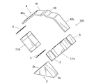
- FIG. 2 is an exploded perspective view of the piezoelectric actuator
- FIG. 3 is a front view of the piezoelectric actuator and an operation target operated by the piezoelectric actuator.
- the piezoelectric actuator 100 operates, for example, a disk hand (for example, a disk hand 510 shown in FIG. 7) constituting a date mechanism of a wristwatch that is an electronic timepiece or the like, and a hand moving mechanism that operates a pointer.
- the operation target R is a rotor or the like connected to a gear or the like constituting such a mechanism. Note that the target to be operated by the piezoelectric actuator 100 is not limited to the example illustrated here.
- the piezoelectric actuator 100 of the present embodiment is fixed to two piezoelectric elements 1 (piezoelectric elements 1a and 1b) as displaceable displacement members and one end side of the piezoelectric elements 1a and 1b. 2, the elastic member 4 fixed to the other end side of the piezoelectric elements 1 a and 1 b, and a transmission portion 43 provided on the elastic member 4.
- piezoelectric element 1 includes the piezoelectric element 1a and the piezoelectric element 1b.
- the two piezoelectric elements 1a and 1b are displacement elements that undergo displacement such as expansion and contraction by applying a voltage.
- the piezoelectric element 1 includes, for example, a laminated type using piezoelectric ceramics.
- the piezoelectric element 1 may be any element that can be expanded and contracted by applying a voltage, vibrates, and causes the transmission unit 43 described later to elliptically move by this vibration (resonance). As long as it exists, it is not limited to this, What was illustrated above may be sufficient.
- the two piezoelectric elements 1 a and 1 b are arranged in a V shape so as to form a predetermined angle, and the ends of the two piezoelectric elements 1 a and 1 b on the intersection point side are fixed to the base 2.
- the base 2 of the present embodiment has a substantially isosceles triangular shape when viewed from the front, and has two inclined surfaces 2a and 2b.
- the base 2 is arranged on the intersection side of the two piezoelectric elements 1a and 1b, and the end of one end side (intersection side) of the piezoelectric element 1a is fixed to the inclined surface 2a via the adhesive layer 3. .
- an end of one end side (intersection side) of the piezoelectric element 1b is fixed to the inclined surface 2b with an adhesive layer 3 interposed therebetween.
- the angle between the inclined surfaces 2a and 2b is approximately 90 degrees
- the angle between the two piezoelectric elements 1a and 1b fixed to the inclined surfaces 2a and 2b is approximately 90 degrees. It has become.
- the base 2 When the piezoelectric actuator 100 is mounted inside the case 501 (see FIG. 7) of the electronic timepiece 500, the base 2 is fixed to a ground plate or a substrate (not shown) by screws or the like. That is, in this embodiment, since a spring or the like constituting the pressurizing mechanism is not disposed under the table 2, the bottom surface, which is one surface of the table 2, can be directly fixed on the ground plate, the substrate, or the like. The table 2 is not deformed even when driven. When the base 2 vibrates and deforms when the piezoelectric actuator 100 is driven, it is necessary to devise a fixing position and a holding method in consideration of deformation of the base 2 and the like. In this respect, in the present embodiment, such a consideration is unnecessary, and thus the fixing position of the base 2 is not limited, and the degree of freedom of the installation position of the piezoelectric actuator 100 is increased.
- the elastic member 4 is a thin plate-like member that is stretched over the expanded side of the piezoelectric elements 1a and 1b, which are two displacement members, and is fixed to the end of the expanded side of the two piezoelectric elements 1a and 1b.
- the elastic member 4 is a member that can be elastically deformed, and is, for example, a leaf spring formed of a thin plate-like iron material or the like.
- the material etc. which form an elastic member are not specifically limited.
- the elastic member 4 is a straight portion 41 in which the central portion in the extending direction between the two piezoelectric elements 1a and 1b (the longitudinal direction of the thin plate-like elastic member 4 and the lateral direction in FIG. 3) is linear.
- On both sides of the straight portion 41 there are inclined portions 42a and 42b which are inclined at substantially the same gradient as the inclined surfaces 2a and 2b of the table 2, respectively.
- An end of the other end side (expansion side) of the piezoelectric element 1a is fixed to the surface of the inclined portion 42a facing the base 2 with the adhesive layer 5 interposed therebetween.
- an end of the other end side (expansion side) of the piezoelectric element 1b is fixed to the surface of the inclined portion 42b on the side facing the base 2 with the adhesive layer 5 interposed therebetween.
- a transmission portion 43 is provided at a substantially central portion (that is, a substantially central portion of the straight portion 41) in the bridging direction between the two piezoelectric elements 1 a and 1 b.
- the transmission part 43 is formed in a protruding shape so as to protrude to the side opposite to the side on which the base 2 is provided by bending a part of the thin plate-like elastic member 4.
- the transmission unit 43 operates so as to draw an elliptical orbit by vibrations of the piezoelectric elements 1a and 1b (hereinafter referred to as “elliptical motion”).
- the transmission unit 43 abuts on the surface of the operation target R in a state assembled in the electronic timepiece 500 (see FIG. 7) or the like, and transmits movement such as vibration of the piezoelectric actuator 100 to the operation target R.
- the elastic member 4 itself provided with the transmission portion 43 is a leaf spring, and the elastic member 4 presses the transmission portion 43 against the operation target R (that is, an upward arrow in FIG. 3). It functions as a pressurizing mechanism that urges in the direction indicated by.
- the transmission part 43 is always in contact with the operation target R in a state where pressure is applied, and when the transmission part 43 performs an elliptical motion as will be described later, the elliptical motion is applied to the movement target R by a frictional force. Communication is possible.
- the transmission part 43 should just be a thing of the shape which can transmit a motion to the operation target object R,
- the shape, formation method, etc. are not specifically limited.
- a substantially mountain-shaped transmission portion 43 is provided in the front view over the width direction of the thin plate-like elastic member 4 (that is, the direction orthogonal to the longitudinal direction of the elastic member 4).
- the transmission part may be a weight-like or columnar protrusion provided at the substantially central part in the longitudinal direction and the width direction of the elastic member 4.
- the transmission portion 43 shown in FIG. 1 and the like is hollow only by bending the thin plate-like elastic member 4, but a rigid body having a high specific gravity is formed in the hollow portion of the projection-like transmission portion 43.
- It may be solid by embedding. In this way, by arranging a rigid body or the like having a high specific gravity in the transmission unit 43, the longitudinal direction of the transmission unit 43 when the piezoelectric element 1 vibrates (resonates) and the case where the transmission unit 43 is left hollow. The amount of displacement in the lateral direction can be increased.
- the two piezoelectric elements 1a and 1b are provided with electrodes (not shown), and voltage applying means 11 (voltage applying means 11a and 11b) are electrically connected to the electrodes, respectively. Yes.
- the voltage applying means 11a and 11b apply an alternating voltage to the piezoelectric elements 1a and 1b.
- the voltage applying means 11a and 11b of the present embodiment input AC voltages with shifted phases to the two piezoelectric elements 1a and 1b, respectively, so that vibrations in the vertical and horizontal directions ( Resonance) and the combination thereof excites elliptical vibration in the transmission portion 43 provided at the center of the elastic member 4.
- vibration (resonance) caused by applying a voltage to the piezoelectric element 1 has a peak in a predetermined frequency band, and the closer the driving frequency of the voltage applied to the piezoelectric element 1 is to the predetermined frequency band, the piezoelectric element 1. Accordingly, the speed of the elliptical motion of the transmission unit 43 (that is, the driving speed of the piezoelectric actuator 100) and the thrust (that is, the driving force of the piezoelectric actuator 100) increase accordingly. For this reason, the voltage applying means 11a and 11b apply a voltage to the two piezoelectric elements 1a and 1b at a driving frequency in a frequency band where the resonance of the piezoelectric elements 1a and 1b peaks.
- FIG. 4 is a graph showing an example of a waveform of an alternating voltage applied to the piezoelectric elements 1a and 1b by the voltage applying means 11a and 11b.
- a waveform CH1 indicated by a solid line in FIG. 4 is a waveform example of an AC voltage applied to the piezoelectric element 1a by the voltage applying unit 11a, and a waveform CH2 indicated by a one-dot chain line is a piezoelectric element 1b by the voltage applying unit 11b. It is an example of a waveform of the alternating voltage applied with respect to. As shown in FIG. 4, a predetermined phase difference is provided between the waveform CH1 and the waveform CH2.
- 5A to 5E show the movement of the piezoelectric actuator 100 when an AC waveform voltage having a phase difference as shown in FIG. 4 is applied to the piezoelectric elements 1a and 1b of the present embodiment. It is the image figure which showed the result of having simulated typically. From the initial state shown in FIG. 5A, when a voltage is first applied to the piezoelectric element 1a by the voltage applying means 11a, the piezoelectric element 1a contracts and deforms as shown in FIG. The elastic member 4 is pulled toward the piezoelectric element 1a (left side in FIG.
- the piezoelectric element 1a contracts and deforms, and as shown in FIG. 5 (e), gradually shown in FIG. 5 (a).
- the entire piezoelectric actuator 100 tilts toward the piezoelectric element 1a (left side in FIG. 5B).
- the voltage application means 11a and 11b provide a phase difference with respect to the piezoelectric elements 1a and 1b and alternately apply an alternating voltage, whereby the piezoelectric actuator 100 is vibrated in the vertical direction and the horizontal direction, and is elastic. Elliptical vibration is excited in the central part of the member 4 and the transmission part 43 moves elliptically.
- FIG. 6 is a diagram illustrating a result of simulating the locus of the transmission unit 43 when an AC waveform voltage having a phase difference as described above is applied to the piezoelectric elements 1a and 1b of the piezoelectric actuator 100.
- an ellipse indicated by a solid line is a plot of the motion of the apex (indicated by a black dot in the diagram of FIG. 6) of the transmission portion 43 of the piezoelectric actuator 100 shown at the lower left of FIG. 6.
- FIG. 6 is a diagram illustrating a result of simulating the locus of the transmission unit 43 when an AC waveform voltage having a phase difference as described above is applied to the piezoelectric elements 1a and 1b of the piezoelectric actuator 100.
- FIG. 7 is a diagram showing a state in which the piezoelectric actuator 100 is mounted inside a case 501 of an electronic timepiece 500 (for example, a wristwatch) provided with hands 502 and the like.
- an electronic timepiece 500 for example, a wristwatch
- the base 2 is fixed on a ground plate or a substrate (not shown) by screws or the like.
- the position etc. in which the stand 2 is provided are not limited to the example of illustration.
- FIG. 7 illustrates a case where the disk needle 510 that displays the date by exposing the numbers from the date window 503 is driven to rotate by the piezoelectric actuator 100 of the present embodiment.
- the transmission unit 43 of the piezoelectric actuator 100 is in contact with an operation target R such as a rotor, and the operation target R is rotated by the elliptical motion of the transmission unit 43.
- a first gear 512 is attached to a rotating shaft (not shown) of the operation target R, and this first gear 512 is not shown (not shown) provided on the rotating shaft 511 of the disc needle 510. Gear).
- numbers representing numbers are sequentially written along the periphery.
- the disk needle 510 rotates about the rotation shaft 511 through the first gear 512.
- the numbers exposed from the date window 503 are switched so that the date can be displayed as appropriate.
- the configuration in which the disk needle 510 is rotated by the piezoelectric actuator 100 is not limited to the example illustrated here.
- more gears may be interposed between the piezoelectric actuator 100 and the disk needle 510.
- the object to be rotationally driven by the piezoelectric actuator 100 is not limited to the disk needle 510.
- the piezoelectric actuator 100 of this embodiment may be used as a drive source for rotating the pointer 502.
- the piezoelectric elements 1a and 1b are fixed on the base 2 having the inclined surfaces 2a and 2b. Specifically, the end of the intersection side of the piezoelectric element 1a is fixed on the inclined surface 2a via the adhesive layer 3, and the intersection side of the piezoelectric element 1b is interposed on the inclined surface 2b via the adhesive layer 3. Fix the end of the. Further, the elastic member 4 having the transmission portion 43 is disposed on the expansion side of the piezoelectric elements 1a and 1b, and an adhesive is applied to the lower side surface (the lower surface in FIG. 3 and the like) of one inclined portion 42a of the elastic member 4.
- the end of the expansion side of the piezoelectric element 1a is fixed via the layer 5, and the expansion of the piezoelectric element 1b via the adhesive layer 5 on the lower side of the other inclined part 42b (the lower side in FIG. 3 etc.). Secure the open end. Further, voltage applying means 11a and 11b are connected to the electrodes of the piezoelectric elements 1a and 1b, respectively. Thereby, the piezoelectric actuator 100 is completed.
- the piezoelectric actuator 100 is incorporated in the electronic timepiece 500, the piezoelectric actuator 100 is disposed at a position where the transmission portion 43 is in contact with the surface of the operation target R such as a rotor, and the base 2 is attached to the ground plate in the case 501 with screws or the like. Fix on the substrate.
- an AC waveform voltage having a phase difference as shown in FIG. 4 is applied to the piezoelectric elements 1a and 1b from the voltage applying means 11a and 11b with a predetermined driving frequency and voltage, for example. Apply by value.
- the piezoelectric elements 1a and 1b alternately expand and contract, and are provided at the central portion of the elastic member 4 connected to the piezoelectric elements 1a and 1b.
- An elliptical motion as shown in FIG. 6 is excited in the transmitted portion 43.
- the transmission unit 43 is in a pressurized state that is always pressed against the surface of the operation target R by the spring force of the elastic member 4, and the elliptical motion of the transmission unit 43 is performed by the frictional force. Is transmitted to. Thereby, the operation target R (for example, the rotor) moves (rotates) in a predetermined direction.
- the piezoelectric actuator 100 includes the two piezoelectric elements 1 which are arranged in a V shape so as to form a predetermined angle and are displaceable displacement members.
- the ends of the intersections of the two piezoelectric elements 1a and 1b are fixed to the base 2, and the ends of the two piezoelectric elements 1a and 1b on the expansion side are fixed to the thin plate-like elastic member 4.
- a transmission portion 43 that abuts on the surface of the operation target R is provided at a substantially central portion in the length direction of the elastic member 4.
- the transmission part 43 since the transmission part 43 is provided in the thin-plate-like elastic member 4 having a spring property, the transmission part 43 can be operated without an additional pressurizing mechanism such as a spring for applying a separate pressure. It can be pressed against the surface of R to provide a pressurized state. For this reason, the number of parts constituting the piezoelectric actuator 100 can be reduced, and a small and simple structure can be obtained. Further, when the driving frequency of the voltage applied from the voltage applying means 11a, 11b to the piezoelectric elements 1a, 1b deviates from the resonance frequency band of the piezoelectric elements 1a, 1b, the driving speed and driving force of the piezoelectric actuator 100 are reduced, and the piezoelectric actuator 100 Drive efficiency is reduced.
- the drive frequency is fixed to the frequency without being changed once it is adjusted to the drive frequency corresponding to the resonance frequency band of the piezoelectric elements 1a and 1b.
- the drive frequency can be set afterwards in consideration of individual differences (manufacturing variation) of the springs of the pressurization mechanism. Adjustments need to be made.
- the elastic member 4 constituting the piezoelectric actuator 100 functions as a pressurizing mechanism that pressurizes the transmission portion 43.
- the piezoelectric actuator 100 can be incorporated into the electronic timepiece 500 or the like. It can be done easily. Further, in the present embodiment, since a spring or the like constituting the pressurizing mechanism is not arranged under the base 2, the bottom surface, which is one surface of the base 2, can be directly fixed on the ground plate or the substrate, and the piezoelectric actuator 100 can be The table 2 is not deformed even when driven. Thereby, when the piezoelectric actuator 100 is incorporated in the electronic timepiece 500 or the like, the fixing method or the fixing position of the base 2 is not limited, and the degree of freedom of the installation position of the piezoelectric actuator 100 is expanded.
- FIG. 8 is a front view of the piezoelectric actuator and the operation object operated by the piezoelectric actuator.
- the piezoelectric actuator 200 includes two piezoelectric elements 1a and 1b similar to those in the first embodiment, and a table 2 that fixes the end of the intersection of the piezoelectric elements 1a and 1b. .
- a thin plate-like elastic member 6 is bridged on the expansion side of the piezoelectric elements 1a and 1b.
- the elastic member 6 is a leaf spring formed of, for example, a thin plate-like iron material as in the first embodiment.
- the elastic member 6 is a straight portion 61 in which the central portion in the extending direction between the two piezoelectric elements 1a and 1b (the longitudinal direction of the thin plate-like elastic member 6 and the lateral direction in FIG. 8) is linear.
- On both sides of the straight portion 61 there are inclined portions 62a and 62b which are inclined at substantially the same gradient as the inclined surfaces 2a and 2b of the table 2, respectively.
- An end of the other end side (expansion side) of the piezoelectric element 1a is fixed to the surface of the inclined portion 62a on the side facing the base 2 with the adhesive layer 5 interposed therebetween.
- the other end side (expanded side) end portion of the piezoelectric element 1b is fixed to the surface of the inclined portion 62b on the side facing the base 2 with the adhesive layer 5 interposed therebetween.
- the elastic member 6 has a thin plate-like shape on the side where the base 2 is provided, which is the substantially central portion (that is, the substantially central portion of the straight portion 61) in the bridging direction between the two piezoelectric elements 1a and 1b.
- a transmission portion 63 formed in a protruding shape by bending a part of the elastic member 6 is provided.
- the transmission unit 63 operates so as to draw an elliptical orbit by vibrations of the piezoelectric elements 1a and 1b (hereinafter referred to as “elliptical motion”).
- the piezoelectric actuator 200 is configured such that the operation target R is disposed on the lower side (lower side in FIG. 8) of the elastic member 6 in a state assembled in an electronic timepiece or the like. And the transmission part 63 contact
- the elastic member 6 itself provided with the transmission portion 63 is a leaf spring, and the elastic member 6 moves the transmission portion 63 to the operation target R. It functions as a pressurizing mechanism that urges in the pressing direction (ie, the direction indicated by the downward arrow in FIG. 8).
- the transmission part 63 is always in contact with the operation target R in a state where pressure is applied.
- the transmission part 63 performs an elliptical motion as described later, the elliptical motion is applied to the movement target R by a frictional force. Communication is possible.
- the transmission part 63 should just be a thing of the shape which can transmit a motion to the operation
- the shape, formation method, etc. are not specifically limited similarly to 1st Embodiment.
- FIG. 9 is a diagram illustrating a result of simulating the locus of the transmission unit 63 when an AC waveform voltage having a phase difference as described above is applied to the piezoelectric elements 1 a and 1 b of the piezoelectric actuator 200.
- an ellipse indicated by a solid line is a plot of the movement of the apex (indicated by a black dot in the drawing of FIG. 9) of the transmission portion 63 of the piezoelectric actuator 200 shown at the lower left of FIG. As shown in FIG.
- the piezoelectric elements 1a and 1b are fixed on the base 2 having the inclined surfaces 2a and 2b, and the transmitting portion 63 is provided on the expansion side of the piezoelectric elements 1a and 1b.
- the elastic member 6 having the elastic member 6 is arranged, and the end portion on the expansion side of the piezoelectric element 1a is fixed to the lower side surface (lower surface in FIG. 8) of one inclined portion 62a of the elastic member 6 through the adhesive layer 5. Then, the end portion on the expansion side of the piezoelectric element 1b is fixed to the lower side surface (the lower surface in FIG. 8) of the other inclined portion 62b via the adhesive layer 5.
- the piezoelectric actuator 200 is completed.
- the piezoelectric actuator 200 is incorporated into an electronic timepiece, the piezoelectric actuator 200 is disposed at a position where the transmission unit 63 is in contact with the surface of the operation target R such as a rotor, and the base 2 or the substrate in the case 501 is attached to the base 2 with screws or the like. Fix it finely.
- the operation target R is disposed below the transmission unit 63, and the transmission unit 63 contacts the operation target R from above while being pressurized.
- the piezoelectric actuator 200 When the piezoelectric actuator 200 is operated, for example, an AC waveform voltage having a phase difference is applied from the voltage applying means 11a and 11b to the piezoelectric elements 1a and 1b at a predetermined driving frequency and voltage value. Thereby, the piezoelectric elements 1a and 1b alternately expand and contract and vibrate alternately, and an elliptical motion as shown in FIG. 9 is caused in the transmission part 63 provided at the center of the elastic member 6 connected to the piezoelectric elements 1a and 1b.
- the transmission unit 63 is in a pressurized state that is always pressed against the surface of the operation target R by the spring force of the elastic member 6, and the elliptical motion of the transmission unit 63 is caused by the frictional force. Is transmitted to. Thereby, the operation target R (for example, the rotor) moves (rotates) in a predetermined direction. Since other points are the same as those described in the first embodiment, description thereof is omitted.
- the transmission part 63 is provided on the lower side of the elastic member 6 (the lower side in FIG. 8, the inner side of the piezoelectric actuator 200), and the operation target R is disposed on the lower side of the transmission part 63. Is done. For this reason, compared with the case where the operation target R is disposed on the upper side of the transmission unit, the space for providing the piezoelectric actuator 200 can be reduced, and it can be easily accommodated in a small case.
- the transmission part 63 that moves elliptically is provided on the thin plate-like elastic member 6.
- the transmission part 63 when the transmission part 63 is arranged on a thin leaf spring, even if the position of the transmission part 63 in contact with the operation target R is slightly changed, the elliptical motion in the transmission part 63 is not significantly affected, and the piezoelectric elements 1a and 1b are not affected. Due to the vibration (resonance), the transmission unit 63 operates in a largely elliptical locus (see the elliptical trajectory shown in FIG. 9). For this reason, even if the transmission part 63 is provided on the lower surface of the thin plate-like elastic member 6, the driving efficiency of the piezoelectric actuator 200 does not decrease, and the piezoelectric actuator 200 can be reduced in size and space-saving while maintaining the driving efficiency. Can do.
- the angle formed between the inclined surfaces 2a and 2b of the base 2 is approximately 90 degrees, and the angle formed between the two piezoelectric elements 1a and 1b fixed to the inclined surfaces 2a and 2b is approximately.
- the angle formed by the two piezoelectric elements 1a and 1b is not limited to approximately 90 degrees.
- the slopes of the inclined surfaces 21a and 21b of the table 21 are made gentle so that the angle formed by the two piezoelectric elements 1a and 1b fixed to the inclined surfaces 21a and 21b is an acute angle of more than 90 degrees. Also good.
- the elastic member 7 also has a shape corresponding to the shape of the base 21, and specifically, the slopes of the inclined parts 72 a and 72 b provided on both sides of the straight part 71 are the slopes of the inclined surfaces 21 a and 21 b of the base 21. It becomes moderate corresponding to.
- the angle formed by the two piezoelectric elements 1a and 1b is an acute angle
- the vertical displacement of the ellipse tends to increase when the locus of the elliptical motion of the transmission unit 73 is viewed.
- the thrust (driving force) of the piezoelectric actuator is improved.
- the slopes of the inclined surfaces 22a and 22b of the base 22 are made steep, and the angle formed by the two piezoelectric elements 1a and 1b fixed to the inclined surfaces 22a and 22b is more than 90 degrees. It may be an obtuse angle.
- the elastic member 8 also has a shape corresponding to the shape of the base 22, and specifically, the inclination of the inclined portions 82 a and 82 b provided on both sides of the straight portion 81 is the gradient of the inclined surfaces 22 a and 22 b of the base 22. suddenly in response to.
- the elliptical lateral displacement tends to increase when the locus of the elliptical motion of the transmission unit 83 transmission unit 83 is viewed. .
- the speed (drive speed) of the piezoelectric actuator is improved.
- the operation object R is disposed below the elastic member (the lower side in FIGS. 10 and 11 and the inner side of the piezoelectric actuator).
- the relationship between the angle formed by the two piezoelectric elements 1a and 1b and the locus of the elliptical motion of the transmission unit is such that the operation target R as shown in the first embodiment is located above the elastic member.
- the method of forming a transmission part is not limited to this.
- the elastic member 9 having the straight portion 91 and the inclined portions 92a and 92b is almost in the crossing direction with respect to the piezoelectric elements 1a and 1b (the longitudinal direction of the elastic member 9 and the lateral direction in FIG. 12).
- the transmitting portion 93 may be configured by attaching a protruding member formed as a separate member by a rigid body having a high specific gravity or the like to the central portion (that is, substantially the central portion of the straight portion 91).
- the material or the like for forming the protruding member is not particularly limited as long as it has rigidity, wear resistance, and the like.
- the method for attaching the protruding member to the elastic member 9 is not particularly limited, and for example, a method such as adhesion fixing or spot welding can be used.
- the operation target R is disposed on the upper side of the elastic member (the upper side in FIG. 12 and the outer side of the piezoelectric actuator) is illustrated. Even when the transmission portion 93 formed by pasting the protrusion-shaped member is disposed on the lower side of the elastic member (lower side in FIG. 12, inner side of the piezoelectric actuator) as shown in the second embodiment. Similar effects can be obtained.
- the transmission portion 43 is located above the elastic member 4 (upper side in FIG. 3 and the like, outside the piezoelectric actuator 100) or the transmission portion 63 is located below the elastic member 6 (lower side in FIG. 8).
- the operation target R is located above the elastic member 4 (upper side in FIG. 3, etc., outside the piezoelectric actuator) corresponding to the transmission parts 43, 63 or below the elastic member 6 (lower side in FIG. 8).
- abut is not limited to this.
- a transmission part is provided on each of the upper side (transmission part 93 in FIG. 13) and the lower side (transmission part 94 in FIG. 13) of the elastic member 9 to correspond to each transmission part 93, 94.
- the operation objects R1 and R2 that operate when the transmission units 93 and 94 come into contact with each other may be disposed at the positions where the transmission is performed.
- the transmission part 93 and the transmission part 94 are arranged on the front and back with the elastic member 9 as a leaf spring interposed therebetween, and the operation objects R1 and R2 are in contact with the transmission part 93 and the transmission part 94, respectively.
- the transmission unit 93 is pressurized against the operation target R1, and the transmission unit 94 is pressurized against the operation target R2.
- the transmission unit 93 provided on the upper side of the elastic member 9 and the lower side of the elastic member 9 are provided.
- Each of the provided transmission portions 94 performs an elliptical motion.
- the transmission unit 93 is in press contact with the operation target R1 in an elliptical motion state, whereby the elliptical motion is transmitted to the operation target R1, and the operation target R1 moves (rotates) in a predetermined direction.
- the transmission unit 94 is pressed against the operation target R2 in an elliptical motion state, whereby the elliptical motion is transmitted to the operation target R2, and the operation target R2 moves (rotates) in a predetermined direction.
- the transmission unit 93 and the transmission unit 94 are arranged above and below the elastic member 9 (front and back, that is, outside and inside of the piezoelectric actuator)
- the two operation objects R1 and R2 are simultaneously moved by one piezoelectric actuator. It is possible to operate, and it is possible to improve the driving efficiency of the piezoelectric actuator by reducing as much as possible the loss of idling without the transmission portion being in contact with the operation target.
- the transmission parts 93 and 94 formed by attaching the protruding members are arranged above and below the elastic member 9 (front and back, that is, outside and inside the piezoelectric actuator),
- the configuration of the portions 93 and 94 is not limited to this, and for example, as shown in the first embodiment and the second embodiment, a hollow transmission portion is formed by bending a thin plate-like elastic member. Even if formed, the same effect can be obtained.
- the voltage application means 11a and 11b respectively input AC voltages with shifted phases to the two piezoelectric elements 1a and 1b, whereby the piezoelectric elements 1a and 1b are longitudinally and laterally input.
- a driving method for generating elliptical vibrations and exciting elliptic vibrations in the transmission portion 43 provided in the center of the elastic member 4 by the combination thereof is illustrated.
- the driving method for driving the piezoelectric actuator is not limited thereto. .
- the piezoelectric element 1 is expanded and contracted, and the expanded and contracted movement is transmitted to the other piezoelectric element 1 via the elastic member 4 and the base 2.
- the other piezoelectric element 1 may be vibrated in conjunction with this movement.
- the piezoelectric elements 1a and 1b vibrate with their phases shifted from each other, thereby generating vibrations in the vertical direction and the horizontal direction, and the combination can excite elliptical vibration in the transmission unit 43.
- the two displacement members are the two piezoelectric elements 1a and 1b as the displacement elements that are displaced by applying a voltage
- the two displacement members are at least one. It is sufficient that the element is a displacement element that is displaced by applying a voltage, and both need not be displacement elements.
- voltage The displacement member on the driven side to which no voltage is applied does not have to be a displacement element such as a piezoelectric element, and may be an elastic member such as a displaceable spring.
- the other displacement member to which no voltage is applied vibrates in conjunction with each other, so that the two displacement members vibrate while out of phase with each other, thereby generating vertical and horizontal vibrations,
- elliptical vibration can be excited in the transmission unit 43.
- the piezoelectric actuator 100 is incorporated in the electronic timepiece 500 , but the target to which the piezoelectric actuator is applied is not limited to the electronic timepiece 500.
- terminal devices such as a pedometer, a heart rate meter, an altimeter, and a barometer.
- the present invention can be widely used for a piezoelectric actuator including a displacement member such as a piezoelectric element and an electronic device such as an electronic timepiece including the piezoelectric actuator.
Landscapes
- General Electrical Machinery Utilizing Piezoelectricity, Electrostriction Or Magnetostriction (AREA)
Abstract
L'invention concerne un actionneur piézoélectrique doté d'une bonne efficacité d'entraînement et une pièce d'horlogerie électronique permettant de réduire les facteurs qui amèneraient la fréquence de résonance de crête de l'actionneur piézoélectrique à fluctuer, ce qui permet de faciliter le réglage de la fréquence d'entraînement et l'installation d'un dispositif. L'actionneur piézoélectrique est pourvu : de deux composants piézoélectriques 1a, 1b qui sont agencés dans une forme en V de manière à former un angle prédéterminé entre eux et à se déformer lorsqu'une tension est appliquée à ceux-ci ; d'une base 2 qui est disposée sur le côté où les deux composants piézoélectriques 1a, 1b se coupent l'un l'autre et fixe les extrémités côté intersection des deux composants piézoélectriques 1a, 1b ; d'un élément élastique en forme de plaque mince 4 qui relie les côtés d'expansion des deux composants piézoélectriques 1a, 1b et est fixé sur les extrémités côté expansion des deux composants piézoélectriques 1a, 1b ; et d'une partie de transmission 43 qui est disposée sur la partie centrale de l'élément élastique 4 dans la direction dans laquelle l'élément élastique 4 relie les deux composants piézoélectriques 1a, 1b.
Applications Claiming Priority (2)
| Application Number | Priority Date | Filing Date | Title |
|---|---|---|---|
| JP2015057476A JP6550823B2 (ja) | 2015-03-20 | 2015-03-20 | 圧電アクチュエータ及び電子時計 |
| JP2015-057476 | 2015-03-20 |
Publications (1)
| Publication Number | Publication Date |
|---|---|
| WO2016152224A1 true WO2016152224A1 (fr) | 2016-09-29 |
Family
ID=56978785
Family Applications (1)
| Application Number | Title | Priority Date | Filing Date |
|---|---|---|---|
| PCT/JP2016/051746 WO2016152224A1 (fr) | 2015-03-20 | 2016-01-21 | Actionneur piézoélectrique et pièce d'horlogerie électronique |
Country Status (2)
| Country | Link |
|---|---|
| JP (1) | JP6550823B2 (fr) |
| WO (1) | WO2016152224A1 (fr) |
Families Citing this family (3)
| Publication number | Priority date | Publication date | Assignee | Title |
|---|---|---|---|---|
| JP7217530B2 (ja) * | 2017-07-07 | 2023-02-03 | 有限会社メカノトランスフォーマ | 変位拡大機構、研磨装置、アクチュエータ、ディスペンサ、及びエアバルブ |
| EP3537594A1 (fr) | 2018-03-09 | 2019-09-11 | ETA SA Manufacture Horlogère Suisse | Moteur piezoelectrique rotatif a precontrainte radiale |
| JP2021052460A (ja) * | 2019-09-24 | 2021-04-01 | ソニー株式会社 | 圧電アクチュエータ、撮像装置 |
Citations (4)
| Publication number | Priority date | Publication date | Assignee | Title |
|---|---|---|---|---|
| JPH05157858A (ja) * | 1991-12-06 | 1993-06-25 | Casio Comput Co Ltd | 電子時計の超音波モータ駆動制御装置 |
| JP2001141633A (ja) * | 1999-08-31 | 2001-05-25 | Seiko Instruments Inc | 走査型プローブ顕微鏡(spm) |
| JP2001161083A (ja) * | 1999-11-03 | 2001-06-12 | Siemens Ag | 電気機械式モータ |
| JP2013070447A (ja) * | 2011-09-20 | 2013-04-18 | Nikon Corp | モータ装置、駆動制御装置、回転子の駆動方法及びロボット装置 |
-
2015
- 2015-03-20 JP JP2015057476A patent/JP6550823B2/ja active Active
-
2016
- 2016-01-21 WO PCT/JP2016/051746 patent/WO2016152224A1/fr active Application Filing
Patent Citations (4)
| Publication number | Priority date | Publication date | Assignee | Title |
|---|---|---|---|---|
| JPH05157858A (ja) * | 1991-12-06 | 1993-06-25 | Casio Comput Co Ltd | 電子時計の超音波モータ駆動制御装置 |
| JP2001141633A (ja) * | 1999-08-31 | 2001-05-25 | Seiko Instruments Inc | 走査型プローブ顕微鏡(spm) |
| JP2001161083A (ja) * | 1999-11-03 | 2001-06-12 | Siemens Ag | 電気機械式モータ |
| JP2013070447A (ja) * | 2011-09-20 | 2013-04-18 | Nikon Corp | モータ装置、駆動制御装置、回転子の駆動方法及びロボット装置 |
Also Published As
| Publication number | Publication date |
|---|---|
| JP6550823B2 (ja) | 2019-07-31 |
| JP2016178806A (ja) | 2016-10-06 |
Similar Documents
| Publication | Publication Date | Title |
|---|---|---|
| JP5765993B2 (ja) | 振動型駆動装置 | |
| JP6255811B2 (ja) | 駆動装置及び時計 | |
| JP2014018027A (ja) | 振動型アクチュエータ、撮像装置、及びステージ | |
| JPWO2008044470A1 (ja) | 光走査装置 | |
| JP2007300426A (ja) | 圧電振動子およびこれを備えた圧電振動発生装置 | |
| WO2016152224A1 (fr) | Actionneur piézoélectrique et pièce d'horlogerie électronique | |
| JP6463951B2 (ja) | 駆動装置 | |
| JP5641800B2 (ja) | 振動型駆動装置 | |
| JP2012058527A (ja) | 光偏向器、光走査装置、画像形成装置及び画像投影装置 | |
| JP2007325466A (ja) | 駆動装置 | |
| JP6422248B2 (ja) | 駆動装置及びそれを有するレンズ駆動装置 | |
| JP6025446B2 (ja) | 振動型アクチュエータ、撮像装置および、振動型アクチュエータを備えた装置 | |
| US7825566B2 (en) | Ultrasonic actuator and method for manufacturing piezoelectric deformation portion used in the same | |
| JP2007336678A (ja) | 超音波振動子の振動特性の調整方法およびそれに用いられる超音波振動子 | |
| JP2015186329A (ja) | 圧電モーター | |
| JP4236957B2 (ja) | 超音波モータ及び超音波モータ付電子機器 | |
| WO2012090847A1 (fr) | Dispositif d'émission d'oscillation et dispositif de présentation de sensation tactile | |
| JP4714722B2 (ja) | 圧電アクチュエータを利用したステージ及びこのステージを用いた電子機器 | |
| JPH11235061A (ja) | 超音波モータおよび超音波モータ付き電子機器 | |
| JP2016178789A (ja) | 圧電駆動装置及び電子時計 | |
| JP6253261B2 (ja) | 振動型アクチュエータおよび光学機器 | |
| JP3614009B2 (ja) | 圧電アクチュエータ、圧電アクチュエータの駆動方法、携帯機器および時計 | |
| JP2008172885A (ja) | 超音波アクチュエータ | |
| JP4981427B2 (ja) | 振動駆動装置 | |
| JPH099655A (ja) | 振動アクチュエータ及びこれを用いる駆動装置 |
Legal Events
| Date | Code | Title | Description |
|---|---|---|---|
| 121 | Ep: the epo has been informed by wipo that ep was designated in this application |
Ref document number: 16768127 Country of ref document: EP Kind code of ref document: A1 |
|
| NENP | Non-entry into the national phase |
Ref country code: DE |
|
| 122 | Ep: pct application non-entry in european phase |
Ref document number: 16768127 Country of ref document: EP Kind code of ref document: A1 |