WO2016152224A1 - Piezoelectric actuator and electronic timepiece - Google Patents
Piezoelectric actuator and electronic timepiece Download PDFInfo
- Publication number
- WO2016152224A1 WO2016152224A1 PCT/JP2016/051746 JP2016051746W WO2016152224A1 WO 2016152224 A1 WO2016152224 A1 WO 2016152224A1 JP 2016051746 W JP2016051746 W JP 2016051746W WO 2016152224 A1 WO2016152224 A1 WO 2016152224A1
- Authority
- WO
- WIPO (PCT)
- Prior art keywords
- piezoelectric actuator
- piezoelectric
- elastic member
- voltage
- transmission
- Prior art date
Links
- 230000005540 biological transmission Effects 0.000 claims abstract description 116
- 238000006073 displacement reaction Methods 0.000 claims description 36
- 238000009434 installation Methods 0.000 abstract description 5
- 230000033001 locomotion Effects 0.000 description 42
- 230000007246 mechanism Effects 0.000 description 13
- 239000012790 adhesive layer Substances 0.000 description 11
- 238000000034 method Methods 0.000 description 11
- 239000000758 substrate Substances 0.000 description 6
- 238000005452 bending Methods 0.000 description 5
- 238000010586 diagram Methods 0.000 description 5
- 230000000694 effects Effects 0.000 description 5
- XEEYBQQBJWHFJM-UHFFFAOYSA-N Iron Chemical compound [Fe] XEEYBQQBJWHFJM-UHFFFAOYSA-N 0.000 description 4
- 230000008602 contraction Effects 0.000 description 4
- 230000005484 gravity Effects 0.000 description 4
- 239000000463 material Substances 0.000 description 4
- 230000004048 modification Effects 0.000 description 4
- 238000012986 modification Methods 0.000 description 4
- 230000001154 acute effect Effects 0.000 description 2
- 230000015572 biosynthetic process Effects 0.000 description 2
- 238000004891 communication Methods 0.000 description 2
- 229910052742 iron Inorganic materials 0.000 description 2
- 238000003825 pressing Methods 0.000 description 2
- 239000000853 adhesive Substances 0.000 description 1
- 230000001070 adhesive effect Effects 0.000 description 1
- 239000000919 ceramic Substances 0.000 description 1
- 239000010410 layer Substances 0.000 description 1
- 238000004519 manufacturing process Methods 0.000 description 1
- 230000008569 process Effects 0.000 description 1
- 230000004044 response Effects 0.000 description 1
- 239000007787 solid Substances 0.000 description 1
- 230000009466 transformation Effects 0.000 description 1
- 238000003466 welding Methods 0.000 description 1
Images


Classifications
-
- H—ELECTRICITY
- H02—GENERATION; CONVERSION OR DISTRIBUTION OF ELECTRIC POWER
- H02N—ELECTRIC MACHINES NOT OTHERWISE PROVIDED FOR
- H02N2/00—Electric machines in general using piezoelectric effect, electrostriction or magnetostriction
Definitions
- the present invention relates to a piezoelectric actuator and an electronic timepiece.
- a piezoelectric actuator including a displacement element (piezoelectric element) that expands and contracts when a voltage is applied.
- the piezoelectric actuator for example, causes mechanical resonance by applying a predetermined voltage to the piezoelectric element, and the transmission unit (columnar protrusion) operates so as to draw an elliptical orbit by this vibration. And the operation
- Japanese Patent Application Laid-Open No. 2009-71903 discloses a configuration including a pressurizing unit that applies pressure using a coil spring.
- the piezoelectric element has a resonance peak when a voltage having a predetermined frequency is applied. For this reason, in order to efficiently resonate the piezoelectric element, it is necessary to adjust the driving frequency when applying a voltage to the piezoelectric element to a frequency band where the resonance reaches a peak.
- a spring such as a coil spring is brought into contact with the piezoelectric actuator and the piezoelectric actuator is pressed by a spring force as in the conventional piezoelectric actuator described in Patent Document 1
- the spring comes into contact with the piezoelectric actuator.
- the frequency band in which the resonance of the piezoelectric element reaches a peak also deviates from the peak frequency band in the case of the piezoelectric actuator alone.
- the conventional piezoelectric actuator has a pressurizing mechanism constituted by a member different from the piezoelectric actuator, and the pressurizing mechanism applies a pressure from one end side to the other end side of the piezoelectric actuator. Yes.
- the operation object with which the transmission part of the piezoelectric actuator comes into contact can be arranged only on the side where the pressure is applied, and the force generated by the expansion / contraction operation of the piezoelectric element cannot be fully utilized. There is also a problem that is bad.
- the table for fixing the piezoelectric element itself is also deformed when the piezoelectric element resonates. For this reason, when the piezoelectric actuator is incorporated in the apparatus, it is necessary to fix the base at a location where the amount of deformation is small, and there is a problem that the installation position and installation method of the piezoelectric actuator are restricted.
- An object of the present invention is to provide a piezoelectric actuator in which a drive frequency can be easily set and an electronic timepiece having the actuator.
- the piezoelectric actuator according to the present invention is: Two displacement members which are arranged in a V shape so as to form a predetermined angle and which are displaced by applying a voltage; A table which is arranged on the intersection side of the two displacement members and fixes the end portion on the intersection point of the two displacement members; A thin plate-like elastic member that is stretched over the expansion side of the two displacement members and fixed to the end of the two displacement members on the expansion side; A transmission portion provided at a central portion in the bridging direction to the two displacement members in the elastic member; It is characterized by having.
- FIG. 2 is a front view of the piezoelectric actuator of FIG. 1 and an operation target operated by the piezoelectric actuator. 2 is a graph showing an example of a waveform of an applied voltage applied to the piezoelectric actuator of FIG. 1.
- (A) to (e) are image diagrams schematically showing results of simulating the movement of the piezoelectric actuator when the voltage having the waveform shown in FIG. 4 is applied to the piezoelectric element of FIG.
- FIG. 1 is a perspective view of a piezoelectric actuator according to the present embodiment
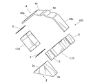
- FIG. 2 is an exploded perspective view of the piezoelectric actuator
- FIG. 3 is a front view of the piezoelectric actuator and an operation target operated by the piezoelectric actuator.
- the piezoelectric actuator 100 operates, for example, a disk hand (for example, a disk hand 510 shown in FIG. 7) constituting a date mechanism of a wristwatch that is an electronic timepiece or the like, and a hand moving mechanism that operates a pointer.
- the operation target R is a rotor or the like connected to a gear or the like constituting such a mechanism. Note that the target to be operated by the piezoelectric actuator 100 is not limited to the example illustrated here.
- the piezoelectric actuator 100 of the present embodiment is fixed to two piezoelectric elements 1 (piezoelectric elements 1a and 1b) as displaceable displacement members and one end side of the piezoelectric elements 1a and 1b. 2, the elastic member 4 fixed to the other end side of the piezoelectric elements 1 a and 1 b, and a transmission portion 43 provided on the elastic member 4.
- piezoelectric element 1 includes the piezoelectric element 1a and the piezoelectric element 1b.
- the two piezoelectric elements 1a and 1b are displacement elements that undergo displacement such as expansion and contraction by applying a voltage.
- the piezoelectric element 1 includes, for example, a laminated type using piezoelectric ceramics.
- the piezoelectric element 1 may be any element that can be expanded and contracted by applying a voltage, vibrates, and causes the transmission unit 43 described later to elliptically move by this vibration (resonance). As long as it exists, it is not limited to this, What was illustrated above may be sufficient.
- the two piezoelectric elements 1 a and 1 b are arranged in a V shape so as to form a predetermined angle, and the ends of the two piezoelectric elements 1 a and 1 b on the intersection point side are fixed to the base 2.
- the base 2 of the present embodiment has a substantially isosceles triangular shape when viewed from the front, and has two inclined surfaces 2a and 2b.
- the base 2 is arranged on the intersection side of the two piezoelectric elements 1a and 1b, and the end of one end side (intersection side) of the piezoelectric element 1a is fixed to the inclined surface 2a via the adhesive layer 3. .
- an end of one end side (intersection side) of the piezoelectric element 1b is fixed to the inclined surface 2b with an adhesive layer 3 interposed therebetween.
- the angle between the inclined surfaces 2a and 2b is approximately 90 degrees
- the angle between the two piezoelectric elements 1a and 1b fixed to the inclined surfaces 2a and 2b is approximately 90 degrees. It has become.
- the base 2 When the piezoelectric actuator 100 is mounted inside the case 501 (see FIG. 7) of the electronic timepiece 500, the base 2 is fixed to a ground plate or a substrate (not shown) by screws or the like. That is, in this embodiment, since a spring or the like constituting the pressurizing mechanism is not disposed under the table 2, the bottom surface, which is one surface of the table 2, can be directly fixed on the ground plate, the substrate, or the like. The table 2 is not deformed even when driven. When the base 2 vibrates and deforms when the piezoelectric actuator 100 is driven, it is necessary to devise a fixing position and a holding method in consideration of deformation of the base 2 and the like. In this respect, in the present embodiment, such a consideration is unnecessary, and thus the fixing position of the base 2 is not limited, and the degree of freedom of the installation position of the piezoelectric actuator 100 is increased.
- the elastic member 4 is a thin plate-like member that is stretched over the expanded side of the piezoelectric elements 1a and 1b, which are two displacement members, and is fixed to the end of the expanded side of the two piezoelectric elements 1a and 1b.
- the elastic member 4 is a member that can be elastically deformed, and is, for example, a leaf spring formed of a thin plate-like iron material or the like.
- the material etc. which form an elastic member are not specifically limited.
- the elastic member 4 is a straight portion 41 in which the central portion in the extending direction between the two piezoelectric elements 1a and 1b (the longitudinal direction of the thin plate-like elastic member 4 and the lateral direction in FIG. 3) is linear.
- On both sides of the straight portion 41 there are inclined portions 42a and 42b which are inclined at substantially the same gradient as the inclined surfaces 2a and 2b of the table 2, respectively.
- An end of the other end side (expansion side) of the piezoelectric element 1a is fixed to the surface of the inclined portion 42a facing the base 2 with the adhesive layer 5 interposed therebetween.
- an end of the other end side (expansion side) of the piezoelectric element 1b is fixed to the surface of the inclined portion 42b on the side facing the base 2 with the adhesive layer 5 interposed therebetween.
- a transmission portion 43 is provided at a substantially central portion (that is, a substantially central portion of the straight portion 41) in the bridging direction between the two piezoelectric elements 1 a and 1 b.
- the transmission part 43 is formed in a protruding shape so as to protrude to the side opposite to the side on which the base 2 is provided by bending a part of the thin plate-like elastic member 4.
- the transmission unit 43 operates so as to draw an elliptical orbit by vibrations of the piezoelectric elements 1a and 1b (hereinafter referred to as “elliptical motion”).
- the transmission unit 43 abuts on the surface of the operation target R in a state assembled in the electronic timepiece 500 (see FIG. 7) or the like, and transmits movement such as vibration of the piezoelectric actuator 100 to the operation target R.
- the elastic member 4 itself provided with the transmission portion 43 is a leaf spring, and the elastic member 4 presses the transmission portion 43 against the operation target R (that is, an upward arrow in FIG. 3). It functions as a pressurizing mechanism that urges in the direction indicated by.
- the transmission part 43 is always in contact with the operation target R in a state where pressure is applied, and when the transmission part 43 performs an elliptical motion as will be described later, the elliptical motion is applied to the movement target R by a frictional force. Communication is possible.
- the transmission part 43 should just be a thing of the shape which can transmit a motion to the operation target object R,
- the shape, formation method, etc. are not specifically limited.
- a substantially mountain-shaped transmission portion 43 is provided in the front view over the width direction of the thin plate-like elastic member 4 (that is, the direction orthogonal to the longitudinal direction of the elastic member 4).
- the transmission part may be a weight-like or columnar protrusion provided at the substantially central part in the longitudinal direction and the width direction of the elastic member 4.
- the transmission portion 43 shown in FIG. 1 and the like is hollow only by bending the thin plate-like elastic member 4, but a rigid body having a high specific gravity is formed in the hollow portion of the projection-like transmission portion 43.
- It may be solid by embedding. In this way, by arranging a rigid body or the like having a high specific gravity in the transmission unit 43, the longitudinal direction of the transmission unit 43 when the piezoelectric element 1 vibrates (resonates) and the case where the transmission unit 43 is left hollow. The amount of displacement in the lateral direction can be increased.
- the two piezoelectric elements 1a and 1b are provided with electrodes (not shown), and voltage applying means 11 (voltage applying means 11a and 11b) are electrically connected to the electrodes, respectively. Yes.
- the voltage applying means 11a and 11b apply an alternating voltage to the piezoelectric elements 1a and 1b.
- the voltage applying means 11a and 11b of the present embodiment input AC voltages with shifted phases to the two piezoelectric elements 1a and 1b, respectively, so that vibrations in the vertical and horizontal directions ( Resonance) and the combination thereof excites elliptical vibration in the transmission portion 43 provided at the center of the elastic member 4.
- vibration (resonance) caused by applying a voltage to the piezoelectric element 1 has a peak in a predetermined frequency band, and the closer the driving frequency of the voltage applied to the piezoelectric element 1 is to the predetermined frequency band, the piezoelectric element 1. Accordingly, the speed of the elliptical motion of the transmission unit 43 (that is, the driving speed of the piezoelectric actuator 100) and the thrust (that is, the driving force of the piezoelectric actuator 100) increase accordingly. For this reason, the voltage applying means 11a and 11b apply a voltage to the two piezoelectric elements 1a and 1b at a driving frequency in a frequency band where the resonance of the piezoelectric elements 1a and 1b peaks.
- FIG. 4 is a graph showing an example of a waveform of an alternating voltage applied to the piezoelectric elements 1a and 1b by the voltage applying means 11a and 11b.
- a waveform CH1 indicated by a solid line in FIG. 4 is a waveform example of an AC voltage applied to the piezoelectric element 1a by the voltage applying unit 11a, and a waveform CH2 indicated by a one-dot chain line is a piezoelectric element 1b by the voltage applying unit 11b. It is an example of a waveform of the alternating voltage applied with respect to. As shown in FIG. 4, a predetermined phase difference is provided between the waveform CH1 and the waveform CH2.
- 5A to 5E show the movement of the piezoelectric actuator 100 when an AC waveform voltage having a phase difference as shown in FIG. 4 is applied to the piezoelectric elements 1a and 1b of the present embodiment. It is the image figure which showed the result of having simulated typically. From the initial state shown in FIG. 5A, when a voltage is first applied to the piezoelectric element 1a by the voltage applying means 11a, the piezoelectric element 1a contracts and deforms as shown in FIG. The elastic member 4 is pulled toward the piezoelectric element 1a (left side in FIG.
- the piezoelectric element 1a contracts and deforms, and as shown in FIG. 5 (e), gradually shown in FIG. 5 (a).
- the entire piezoelectric actuator 100 tilts toward the piezoelectric element 1a (left side in FIG. 5B).
- the voltage application means 11a and 11b provide a phase difference with respect to the piezoelectric elements 1a and 1b and alternately apply an alternating voltage, whereby the piezoelectric actuator 100 is vibrated in the vertical direction and the horizontal direction, and is elastic. Elliptical vibration is excited in the central part of the member 4 and the transmission part 43 moves elliptically.
- FIG. 6 is a diagram illustrating a result of simulating the locus of the transmission unit 43 when an AC waveform voltage having a phase difference as described above is applied to the piezoelectric elements 1a and 1b of the piezoelectric actuator 100.
- an ellipse indicated by a solid line is a plot of the motion of the apex (indicated by a black dot in the diagram of FIG. 6) of the transmission portion 43 of the piezoelectric actuator 100 shown at the lower left of FIG. 6.
- FIG. 6 is a diagram illustrating a result of simulating the locus of the transmission unit 43 when an AC waveform voltage having a phase difference as described above is applied to the piezoelectric elements 1a and 1b of the piezoelectric actuator 100.
- FIG. 7 is a diagram showing a state in which the piezoelectric actuator 100 is mounted inside a case 501 of an electronic timepiece 500 (for example, a wristwatch) provided with hands 502 and the like.
- an electronic timepiece 500 for example, a wristwatch
- the base 2 is fixed on a ground plate or a substrate (not shown) by screws or the like.
- the position etc. in which the stand 2 is provided are not limited to the example of illustration.
- FIG. 7 illustrates a case where the disk needle 510 that displays the date by exposing the numbers from the date window 503 is driven to rotate by the piezoelectric actuator 100 of the present embodiment.
- the transmission unit 43 of the piezoelectric actuator 100 is in contact with an operation target R such as a rotor, and the operation target R is rotated by the elliptical motion of the transmission unit 43.
- a first gear 512 is attached to a rotating shaft (not shown) of the operation target R, and this first gear 512 is not shown (not shown) provided on the rotating shaft 511 of the disc needle 510. Gear).
- numbers representing numbers are sequentially written along the periphery.
- the disk needle 510 rotates about the rotation shaft 511 through the first gear 512.
- the numbers exposed from the date window 503 are switched so that the date can be displayed as appropriate.
- the configuration in which the disk needle 510 is rotated by the piezoelectric actuator 100 is not limited to the example illustrated here.
- more gears may be interposed between the piezoelectric actuator 100 and the disk needle 510.
- the object to be rotationally driven by the piezoelectric actuator 100 is not limited to the disk needle 510.
- the piezoelectric actuator 100 of this embodiment may be used as a drive source for rotating the pointer 502.
- the piezoelectric elements 1a and 1b are fixed on the base 2 having the inclined surfaces 2a and 2b. Specifically, the end of the intersection side of the piezoelectric element 1a is fixed on the inclined surface 2a via the adhesive layer 3, and the intersection side of the piezoelectric element 1b is interposed on the inclined surface 2b via the adhesive layer 3. Fix the end of the. Further, the elastic member 4 having the transmission portion 43 is disposed on the expansion side of the piezoelectric elements 1a and 1b, and an adhesive is applied to the lower side surface (the lower surface in FIG. 3 and the like) of one inclined portion 42a of the elastic member 4.
- the end of the expansion side of the piezoelectric element 1a is fixed via the layer 5, and the expansion of the piezoelectric element 1b via the adhesive layer 5 on the lower side of the other inclined part 42b (the lower side in FIG. 3 etc.). Secure the open end. Further, voltage applying means 11a and 11b are connected to the electrodes of the piezoelectric elements 1a and 1b, respectively. Thereby, the piezoelectric actuator 100 is completed.
- the piezoelectric actuator 100 is incorporated in the electronic timepiece 500, the piezoelectric actuator 100 is disposed at a position where the transmission portion 43 is in contact with the surface of the operation target R such as a rotor, and the base 2 is attached to the ground plate in the case 501 with screws or the like. Fix on the substrate.
- an AC waveform voltage having a phase difference as shown in FIG. 4 is applied to the piezoelectric elements 1a and 1b from the voltage applying means 11a and 11b with a predetermined driving frequency and voltage, for example. Apply by value.
- the piezoelectric elements 1a and 1b alternately expand and contract, and are provided at the central portion of the elastic member 4 connected to the piezoelectric elements 1a and 1b.
- An elliptical motion as shown in FIG. 6 is excited in the transmitted portion 43.
- the transmission unit 43 is in a pressurized state that is always pressed against the surface of the operation target R by the spring force of the elastic member 4, and the elliptical motion of the transmission unit 43 is performed by the frictional force. Is transmitted to. Thereby, the operation target R (for example, the rotor) moves (rotates) in a predetermined direction.
- the piezoelectric actuator 100 includes the two piezoelectric elements 1 which are arranged in a V shape so as to form a predetermined angle and are displaceable displacement members.
- the ends of the intersections of the two piezoelectric elements 1a and 1b are fixed to the base 2, and the ends of the two piezoelectric elements 1a and 1b on the expansion side are fixed to the thin plate-like elastic member 4.
- a transmission portion 43 that abuts on the surface of the operation target R is provided at a substantially central portion in the length direction of the elastic member 4.
- the transmission part 43 since the transmission part 43 is provided in the thin-plate-like elastic member 4 having a spring property, the transmission part 43 can be operated without an additional pressurizing mechanism such as a spring for applying a separate pressure. It can be pressed against the surface of R to provide a pressurized state. For this reason, the number of parts constituting the piezoelectric actuator 100 can be reduced, and a small and simple structure can be obtained. Further, when the driving frequency of the voltage applied from the voltage applying means 11a, 11b to the piezoelectric elements 1a, 1b deviates from the resonance frequency band of the piezoelectric elements 1a, 1b, the driving speed and driving force of the piezoelectric actuator 100 are reduced, and the piezoelectric actuator 100 Drive efficiency is reduced.
- the drive frequency is fixed to the frequency without being changed once it is adjusted to the drive frequency corresponding to the resonance frequency band of the piezoelectric elements 1a and 1b.
- the drive frequency can be set afterwards in consideration of individual differences (manufacturing variation) of the springs of the pressurization mechanism. Adjustments need to be made.
- the elastic member 4 constituting the piezoelectric actuator 100 functions as a pressurizing mechanism that pressurizes the transmission portion 43.
- the piezoelectric actuator 100 can be incorporated into the electronic timepiece 500 or the like. It can be done easily. Further, in the present embodiment, since a spring or the like constituting the pressurizing mechanism is not arranged under the base 2, the bottom surface, which is one surface of the base 2, can be directly fixed on the ground plate or the substrate, and the piezoelectric actuator 100 can be The table 2 is not deformed even when driven. Thereby, when the piezoelectric actuator 100 is incorporated in the electronic timepiece 500 or the like, the fixing method or the fixing position of the base 2 is not limited, and the degree of freedom of the installation position of the piezoelectric actuator 100 is expanded.
- FIG. 8 is a front view of the piezoelectric actuator and the operation object operated by the piezoelectric actuator.
- the piezoelectric actuator 200 includes two piezoelectric elements 1a and 1b similar to those in the first embodiment, and a table 2 that fixes the end of the intersection of the piezoelectric elements 1a and 1b. .
- a thin plate-like elastic member 6 is bridged on the expansion side of the piezoelectric elements 1a and 1b.
- the elastic member 6 is a leaf spring formed of, for example, a thin plate-like iron material as in the first embodiment.
- the elastic member 6 is a straight portion 61 in which the central portion in the extending direction between the two piezoelectric elements 1a and 1b (the longitudinal direction of the thin plate-like elastic member 6 and the lateral direction in FIG. 8) is linear.
- On both sides of the straight portion 61 there are inclined portions 62a and 62b which are inclined at substantially the same gradient as the inclined surfaces 2a and 2b of the table 2, respectively.
- An end of the other end side (expansion side) of the piezoelectric element 1a is fixed to the surface of the inclined portion 62a on the side facing the base 2 with the adhesive layer 5 interposed therebetween.
- the other end side (expanded side) end portion of the piezoelectric element 1b is fixed to the surface of the inclined portion 62b on the side facing the base 2 with the adhesive layer 5 interposed therebetween.
- the elastic member 6 has a thin plate-like shape on the side where the base 2 is provided, which is the substantially central portion (that is, the substantially central portion of the straight portion 61) in the bridging direction between the two piezoelectric elements 1a and 1b.
- a transmission portion 63 formed in a protruding shape by bending a part of the elastic member 6 is provided.
- the transmission unit 63 operates so as to draw an elliptical orbit by vibrations of the piezoelectric elements 1a and 1b (hereinafter referred to as “elliptical motion”).
- the piezoelectric actuator 200 is configured such that the operation target R is disposed on the lower side (lower side in FIG. 8) of the elastic member 6 in a state assembled in an electronic timepiece or the like. And the transmission part 63 contact
- the elastic member 6 itself provided with the transmission portion 63 is a leaf spring, and the elastic member 6 moves the transmission portion 63 to the operation target R. It functions as a pressurizing mechanism that urges in the pressing direction (ie, the direction indicated by the downward arrow in FIG. 8).
- the transmission part 63 is always in contact with the operation target R in a state where pressure is applied.
- the transmission part 63 performs an elliptical motion as described later, the elliptical motion is applied to the movement target R by a frictional force. Communication is possible.
- the transmission part 63 should just be a thing of the shape which can transmit a motion to the operation
- the shape, formation method, etc. are not specifically limited similarly to 1st Embodiment.
- FIG. 9 is a diagram illustrating a result of simulating the locus of the transmission unit 63 when an AC waveform voltage having a phase difference as described above is applied to the piezoelectric elements 1 a and 1 b of the piezoelectric actuator 200.
- an ellipse indicated by a solid line is a plot of the movement of the apex (indicated by a black dot in the drawing of FIG. 9) of the transmission portion 63 of the piezoelectric actuator 200 shown at the lower left of FIG. As shown in FIG.
- the piezoelectric elements 1a and 1b are fixed on the base 2 having the inclined surfaces 2a and 2b, and the transmitting portion 63 is provided on the expansion side of the piezoelectric elements 1a and 1b.
- the elastic member 6 having the elastic member 6 is arranged, and the end portion on the expansion side of the piezoelectric element 1a is fixed to the lower side surface (lower surface in FIG. 8) of one inclined portion 62a of the elastic member 6 through the adhesive layer 5. Then, the end portion on the expansion side of the piezoelectric element 1b is fixed to the lower side surface (the lower surface in FIG. 8) of the other inclined portion 62b via the adhesive layer 5.
- the piezoelectric actuator 200 is completed.
- the piezoelectric actuator 200 is incorporated into an electronic timepiece, the piezoelectric actuator 200 is disposed at a position where the transmission unit 63 is in contact with the surface of the operation target R such as a rotor, and the base 2 or the substrate in the case 501 is attached to the base 2 with screws or the like. Fix it finely.
- the operation target R is disposed below the transmission unit 63, and the transmission unit 63 contacts the operation target R from above while being pressurized.
- the piezoelectric actuator 200 When the piezoelectric actuator 200 is operated, for example, an AC waveform voltage having a phase difference is applied from the voltage applying means 11a and 11b to the piezoelectric elements 1a and 1b at a predetermined driving frequency and voltage value. Thereby, the piezoelectric elements 1a and 1b alternately expand and contract and vibrate alternately, and an elliptical motion as shown in FIG. 9 is caused in the transmission part 63 provided at the center of the elastic member 6 connected to the piezoelectric elements 1a and 1b.
- the transmission unit 63 is in a pressurized state that is always pressed against the surface of the operation target R by the spring force of the elastic member 6, and the elliptical motion of the transmission unit 63 is caused by the frictional force. Is transmitted to. Thereby, the operation target R (for example, the rotor) moves (rotates) in a predetermined direction. Since other points are the same as those described in the first embodiment, description thereof is omitted.
- the transmission part 63 is provided on the lower side of the elastic member 6 (the lower side in FIG. 8, the inner side of the piezoelectric actuator 200), and the operation target R is disposed on the lower side of the transmission part 63. Is done. For this reason, compared with the case where the operation target R is disposed on the upper side of the transmission unit, the space for providing the piezoelectric actuator 200 can be reduced, and it can be easily accommodated in a small case.
- the transmission part 63 that moves elliptically is provided on the thin plate-like elastic member 6.
- the transmission part 63 when the transmission part 63 is arranged on a thin leaf spring, even if the position of the transmission part 63 in contact with the operation target R is slightly changed, the elliptical motion in the transmission part 63 is not significantly affected, and the piezoelectric elements 1a and 1b are not affected. Due to the vibration (resonance), the transmission unit 63 operates in a largely elliptical locus (see the elliptical trajectory shown in FIG. 9). For this reason, even if the transmission part 63 is provided on the lower surface of the thin plate-like elastic member 6, the driving efficiency of the piezoelectric actuator 200 does not decrease, and the piezoelectric actuator 200 can be reduced in size and space-saving while maintaining the driving efficiency. Can do.
- the angle formed between the inclined surfaces 2a and 2b of the base 2 is approximately 90 degrees, and the angle formed between the two piezoelectric elements 1a and 1b fixed to the inclined surfaces 2a and 2b is approximately.
- the angle formed by the two piezoelectric elements 1a and 1b is not limited to approximately 90 degrees.
- the slopes of the inclined surfaces 21a and 21b of the table 21 are made gentle so that the angle formed by the two piezoelectric elements 1a and 1b fixed to the inclined surfaces 21a and 21b is an acute angle of more than 90 degrees. Also good.
- the elastic member 7 also has a shape corresponding to the shape of the base 21, and specifically, the slopes of the inclined parts 72 a and 72 b provided on both sides of the straight part 71 are the slopes of the inclined surfaces 21 a and 21 b of the base 21. It becomes moderate corresponding to.
- the angle formed by the two piezoelectric elements 1a and 1b is an acute angle
- the vertical displacement of the ellipse tends to increase when the locus of the elliptical motion of the transmission unit 73 is viewed.
- the thrust (driving force) of the piezoelectric actuator is improved.
- the slopes of the inclined surfaces 22a and 22b of the base 22 are made steep, and the angle formed by the two piezoelectric elements 1a and 1b fixed to the inclined surfaces 22a and 22b is more than 90 degrees. It may be an obtuse angle.
- the elastic member 8 also has a shape corresponding to the shape of the base 22, and specifically, the inclination of the inclined portions 82 a and 82 b provided on both sides of the straight portion 81 is the gradient of the inclined surfaces 22 a and 22 b of the base 22. suddenly in response to.
- the elliptical lateral displacement tends to increase when the locus of the elliptical motion of the transmission unit 83 transmission unit 83 is viewed. .
- the speed (drive speed) of the piezoelectric actuator is improved.
- the operation object R is disposed below the elastic member (the lower side in FIGS. 10 and 11 and the inner side of the piezoelectric actuator).
- the relationship between the angle formed by the two piezoelectric elements 1a and 1b and the locus of the elliptical motion of the transmission unit is such that the operation target R as shown in the first embodiment is located above the elastic member.
- the method of forming a transmission part is not limited to this.
- the elastic member 9 having the straight portion 91 and the inclined portions 92a and 92b is almost in the crossing direction with respect to the piezoelectric elements 1a and 1b (the longitudinal direction of the elastic member 9 and the lateral direction in FIG. 12).
- the transmitting portion 93 may be configured by attaching a protruding member formed as a separate member by a rigid body having a high specific gravity or the like to the central portion (that is, substantially the central portion of the straight portion 91).
- the material or the like for forming the protruding member is not particularly limited as long as it has rigidity, wear resistance, and the like.
- the method for attaching the protruding member to the elastic member 9 is not particularly limited, and for example, a method such as adhesion fixing or spot welding can be used.
- the operation target R is disposed on the upper side of the elastic member (the upper side in FIG. 12 and the outer side of the piezoelectric actuator) is illustrated. Even when the transmission portion 93 formed by pasting the protrusion-shaped member is disposed on the lower side of the elastic member (lower side in FIG. 12, inner side of the piezoelectric actuator) as shown in the second embodiment. Similar effects can be obtained.
- the transmission portion 43 is located above the elastic member 4 (upper side in FIG. 3 and the like, outside the piezoelectric actuator 100) or the transmission portion 63 is located below the elastic member 6 (lower side in FIG. 8).
- the operation target R is located above the elastic member 4 (upper side in FIG. 3, etc., outside the piezoelectric actuator) corresponding to the transmission parts 43, 63 or below the elastic member 6 (lower side in FIG. 8).
- abut is not limited to this.
- a transmission part is provided on each of the upper side (transmission part 93 in FIG. 13) and the lower side (transmission part 94 in FIG. 13) of the elastic member 9 to correspond to each transmission part 93, 94.
- the operation objects R1 and R2 that operate when the transmission units 93 and 94 come into contact with each other may be disposed at the positions where the transmission is performed.
- the transmission part 93 and the transmission part 94 are arranged on the front and back with the elastic member 9 as a leaf spring interposed therebetween, and the operation objects R1 and R2 are in contact with the transmission part 93 and the transmission part 94, respectively.
- the transmission unit 93 is pressurized against the operation target R1, and the transmission unit 94 is pressurized against the operation target R2.
- the transmission unit 93 provided on the upper side of the elastic member 9 and the lower side of the elastic member 9 are provided.
- Each of the provided transmission portions 94 performs an elliptical motion.
- the transmission unit 93 is in press contact with the operation target R1 in an elliptical motion state, whereby the elliptical motion is transmitted to the operation target R1, and the operation target R1 moves (rotates) in a predetermined direction.
- the transmission unit 94 is pressed against the operation target R2 in an elliptical motion state, whereby the elliptical motion is transmitted to the operation target R2, and the operation target R2 moves (rotates) in a predetermined direction.
- the transmission unit 93 and the transmission unit 94 are arranged above and below the elastic member 9 (front and back, that is, outside and inside of the piezoelectric actuator)
- the two operation objects R1 and R2 are simultaneously moved by one piezoelectric actuator. It is possible to operate, and it is possible to improve the driving efficiency of the piezoelectric actuator by reducing as much as possible the loss of idling without the transmission portion being in contact with the operation target.
- the transmission parts 93 and 94 formed by attaching the protruding members are arranged above and below the elastic member 9 (front and back, that is, outside and inside the piezoelectric actuator),
- the configuration of the portions 93 and 94 is not limited to this, and for example, as shown in the first embodiment and the second embodiment, a hollow transmission portion is formed by bending a thin plate-like elastic member. Even if formed, the same effect can be obtained.
- the voltage application means 11a and 11b respectively input AC voltages with shifted phases to the two piezoelectric elements 1a and 1b, whereby the piezoelectric elements 1a and 1b are longitudinally and laterally input.
- a driving method for generating elliptical vibrations and exciting elliptic vibrations in the transmission portion 43 provided in the center of the elastic member 4 by the combination thereof is illustrated.
- the driving method for driving the piezoelectric actuator is not limited thereto. .
- the piezoelectric element 1 is expanded and contracted, and the expanded and contracted movement is transmitted to the other piezoelectric element 1 via the elastic member 4 and the base 2.
- the other piezoelectric element 1 may be vibrated in conjunction with this movement.
- the piezoelectric elements 1a and 1b vibrate with their phases shifted from each other, thereby generating vibrations in the vertical direction and the horizontal direction, and the combination can excite elliptical vibration in the transmission unit 43.
- the two displacement members are the two piezoelectric elements 1a and 1b as the displacement elements that are displaced by applying a voltage
- the two displacement members are at least one. It is sufficient that the element is a displacement element that is displaced by applying a voltage, and both need not be displacement elements.
- voltage The displacement member on the driven side to which no voltage is applied does not have to be a displacement element such as a piezoelectric element, and may be an elastic member such as a displaceable spring.
- the other displacement member to which no voltage is applied vibrates in conjunction with each other, so that the two displacement members vibrate while out of phase with each other, thereby generating vertical and horizontal vibrations,
- elliptical vibration can be excited in the transmission unit 43.
- the piezoelectric actuator 100 is incorporated in the electronic timepiece 500 , but the target to which the piezoelectric actuator is applied is not limited to the electronic timepiece 500.
- terminal devices such as a pedometer, a heart rate meter, an altimeter, and a barometer.
- the present invention can be widely used for a piezoelectric actuator including a displacement member such as a piezoelectric element and an electronic device such as an electronic timepiece including the piezoelectric actuator.
Abstract
Provided are a piezoelectric actuator with good drive efficiency and an electronic timepiece such that factors that would cause the peak resonance frequency of the piezoelectric actuator to fluctuate are reduced, thereby facilitating drive frequency setting and device installation. The piezoelectric actuator is provided with: two piezoelectric components 1a, 1b that are arranged in a V-shape so as to form a predetermined angle therebetween and deform when a voltage is applied thereto; a base 2 that is disposed on the side where the two piezoelectric components 1a, 1b intersect with each other and secures the intersection-side ends of the two piezoelectric components 1a, 1b; a thin plate-like elastic member 4 that bridges the expanding sides of the two piezoelectric components 1a, 1b and is fixed to the expanding side ends of the two piezoelectric components 1a, 1b; and a transmission part 43 that is disposed on the center part of the elastic member 4 in the direction in which the elastic member 4 bridges the two piezoelectric components 1a, 1b.
Description
本発明は、圧電アクチュエータ及び電子時計に関するものである。
The present invention relates to a piezoelectric actuator and an electronic timepiece.
従来、電圧を印加することにより伸縮する変位素子(圧電素子)を備える圧電アクチュエータが知られている。
圧電アクチュエータは、例えば、圧電素子に所定の電圧を印加することにより機械的な共振を起こし、この振動により伝達部(柱状突起)が楕円軌道を描くように動作する。そして、この伝達部の楕円運動によって、伝達部に加圧接触されている動作対象物を移動(駆動)させるようになっている(例えば、特許文献1参照)。 Conventionally, a piezoelectric actuator including a displacement element (piezoelectric element) that expands and contracts when a voltage is applied is known.
The piezoelectric actuator, for example, causes mechanical resonance by applying a predetermined voltage to the piezoelectric element, and the transmission unit (columnar protrusion) operates so as to draw an elliptical orbit by this vibration. And the operation | movement target object press-contacted to a transmission part is moved (driving) by the elliptical motion of this transmission part (for example, refer patent document 1).
このような圧電アクチュエータでは、伝達部の楕円運動を動作対象物に伝達させるために、伝達部を動作対象物に対して加圧接触させて摩擦力を生起させることが必要であり、例えば、日本の特許文献である特開2009-71903号公報には、コイルスプリングを利用して加圧を行う与圧手段を備える構成が開示されている。
In such a piezoelectric actuator, in order to transmit the elliptical motion of the transmission unit to the operation target, it is necessary to cause the transmission unit to press and contact the operation target to generate a frictional force. Japanese Patent Application Laid-Open No. 2009-71903 discloses a configuration including a pressurizing unit that applies pressure using a coil spring.
圧電素子は、所定の周波数の電圧を印加したときに共振がピークとなる。このため、圧電素子を効率よく共振させるためには、圧電素子に電圧を印可する際の駆動周波数を共振がピークとなる周波数帯に調整することが必要となる。
しかしながら、特許文献1に記載されているような従来の圧電アクチュエータのように、コイルスプリング等のバネを圧電アクチュエータに接触させてバネ力によって圧電アクチュエータを押圧する構成の場合、バネが接触することによって圧電素子の共振がピークとなる周波数帯も圧電アクチュエータ単体の場合にピークとなる周波数帯からずれてしまう。
このため、圧電アクチュエータ単体について駆動周波数の調整を行っても、バネ等を取り付けた組み込み状態において、バネを追加したことによる共振周波数のずれを考慮して、再度駆動周波数を調整し直さなければならないという問題がある。 The piezoelectric element has a resonance peak when a voltage having a predetermined frequency is applied. For this reason, in order to efficiently resonate the piezoelectric element, it is necessary to adjust the driving frequency when applying a voltage to the piezoelectric element to a frequency band where the resonance reaches a peak.
However, in the case of a configuration in which a spring such as a coil spring is brought into contact with the piezoelectric actuator and the piezoelectric actuator is pressed by a spring force as in the conventional piezoelectric actuator described in Patent Document 1, the spring comes into contact with the piezoelectric actuator. The frequency band in which the resonance of the piezoelectric element reaches a peak also deviates from the peak frequency band in the case of the piezoelectric actuator alone.
For this reason, even if the drive frequency is adjusted for a single piezoelectric actuator, the drive frequency must be adjusted again in consideration of the shift in the resonance frequency due to the addition of the spring in the assembled state in which the spring or the like is attached. There is a problem.
また、従来の圧電アクチュエータでは、圧電アクチュエータとは別部材で構成された与圧機構を有し、この与圧機構によって圧電アクチュエータの一端側から他端側に向けて与圧をかけるようになっている。このため、圧電アクチュエータの伝達部が当接する動作対象物は与圧がかかる側にしか配置することができず、圧電素子の伸縮動作によって生じた力を十分に活用することができず、駆動効率が悪いとの問題もある。
In addition, the conventional piezoelectric actuator has a pressurizing mechanism constituted by a member different from the piezoelectric actuator, and the pressurizing mechanism applies a pressure from one end side to the other end side of the piezoelectric actuator. Yes. For this reason, the operation object with which the transmission part of the piezoelectric actuator comes into contact can be arranged only on the side where the pressure is applied, and the force generated by the expansion / contraction operation of the piezoelectric element cannot be fully utilized. There is also a problem that is bad.
さらに、圧電アクチュエータを外部から与圧する場合には、圧電素子等を固定する台自体も圧電素子の共振時に変形してしまう。このため、圧電アクチュエータを装置内に組み込む際には台をその変形量の少ない箇所で固定する必要があり、圧電アクチュエータの設置位置や設置手法が制約されてしまうとの問題もある。
Furthermore, when the piezoelectric actuator is pressurized from the outside, the table for fixing the piezoelectric element itself is also deformed when the piezoelectric element resonates. For this reason, when the piezoelectric actuator is incorporated in the apparatus, it is necessary to fix the base at a location where the amount of deformation is small, and there is a problem that the installation position and installation method of the piezoelectric actuator are restricted.
本発明は、駆動周波数の設定が容易な圧電アクチュエータ及びそのアクチュエータを備えた電子時計を提供することを目的とするものである。
An object of the present invention is to provide a piezoelectric actuator in which a drive frequency can be easily set and an electronic timepiece having the actuator.
前記課題を解決するために、本発明に係る圧電アクチュエータは、
所定の角度をなすようにV字状に配置され、電圧を印加することで変位する2つの変位部材と、
前記2つの変位部材の交点側に配置され、前記2つの変位部材の交点側の端部を固定する台と、
前記2つの変位部材の拡開側に架け渡され、前記2つの変位部材の拡開側の端部に固定された薄板状の弾性部材と、
前記弾性部材における前記2つの変位部材への架け渡し方向の中央部に設けられた伝達部と、
を備えることを特徴としている。 In order to solve the above problems, the piezoelectric actuator according to the present invention is:
Two displacement members which are arranged in a V shape so as to form a predetermined angle and which are displaced by applying a voltage;
A table which is arranged on the intersection side of the two displacement members and fixes the end portion on the intersection point of the two displacement members;
A thin plate-like elastic member that is stretched over the expansion side of the two displacement members and fixed to the end of the two displacement members on the expansion side;
A transmission portion provided at a central portion in the bridging direction to the two displacement members in the elastic member;
It is characterized by having.
[第1の実施形態]
以下、図1から図7を参照しつつ、本発明に係る圧電アクチュエータ及び電子時計の第1の実施形態について説明する。
なお、以下に述べる実施形態には、本発明を実施するために技術的に好ましい種々の限定が付されているが、本発明の範囲を以下の実施形態及び図示例に限定するものではない。 [First Embodiment]
Hereinafter, a first embodiment of a piezoelectric actuator and an electronic timepiece according to the invention will be described with reference to FIGS. 1 to 7.
The embodiments described below are given various technically preferable limitations for carrying out the present invention, but the scope of the present invention is not limited to the following embodiments and illustrated examples.
図1は、本実施形態における圧電アクチュエータの斜視図であり、図2は、圧電アクチュエータの分解斜視図であり、図3は、圧電アクチュエータとこれにより動作する動作対象物の正面図である。
本実施形態に係る圧電アクチュエータ100は、例えば電子時計である腕時計の日付機構等を構成するディスク針(例えば図7に示すディスク針510)を回転駆動させたり指針を動作させる運針機構を動作させるために適用されるものであり、動作対象物Rは、こうした機構を構成する歯車等と接続されるロータ等である。なお、圧電アクチュエータ100により動作させる対象は、ここに例示したものに限定されない。 FIG. 1 is a perspective view of a piezoelectric actuator according to the present embodiment, FIG. 2 is an exploded perspective view of the piezoelectric actuator, and FIG. 3 is a front view of the piezoelectric actuator and an operation target operated by the piezoelectric actuator.
Thepiezoelectric actuator 100 according to the present embodiment operates, for example, a disk hand (for example, a disk hand 510 shown in FIG. 7) constituting a date mechanism of a wristwatch that is an electronic timepiece or the like, and a hand moving mechanism that operates a pointer. The operation target R is a rotor or the like connected to a gear or the like constituting such a mechanism. Note that the target to be operated by the piezoelectric actuator 100 is not limited to the example illustrated here.
本実施形態に係る圧電アクチュエータ100は、例えば電子時計である腕時計の日付機構等を構成するディスク針(例えば図7に示すディスク針510)を回転駆動させたり指針を動作させる運針機構を動作させるために適用されるものであり、動作対象物Rは、こうした機構を構成する歯車等と接続されるロータ等である。なお、圧電アクチュエータ100により動作させる対象は、ここに例示したものに限定されない。 FIG. 1 is a perspective view of a piezoelectric actuator according to the present embodiment, FIG. 2 is an exploded perspective view of the piezoelectric actuator, and FIG. 3 is a front view of the piezoelectric actuator and an operation target operated by the piezoelectric actuator.
The
図1から図3に示すように、本実施形態の圧電アクチュエータ100は、変位可能な変位部材としての2つの圧電素子1(圧電素子1a,1b)と、圧電素子1a,1bの一端側に固定される台2と、圧電素子1a,1bの他端側に固定される弾性部材4と、弾性部材4に設けられた伝達部43とを備えている。
なお、以下において、単に圧電素子1としたときは、圧電素子1a及び圧電素子1bを含むものとする。 As shown in FIGS. 1 to 3, thepiezoelectric actuator 100 of the present embodiment is fixed to two piezoelectric elements 1 ( piezoelectric elements 1a and 1b) as displaceable displacement members and one end side of the piezoelectric elements 1a and 1b. 2, the elastic member 4 fixed to the other end side of the piezoelectric elements 1 a and 1 b, and a transmission portion 43 provided on the elastic member 4.
In the following, the term “piezoelectric element 1” includes thepiezoelectric element 1a and the piezoelectric element 1b.
なお、以下において、単に圧電素子1としたときは、圧電素子1a及び圧電素子1bを含むものとする。 As shown in FIGS. 1 to 3, the
In the following, the term “piezoelectric element 1” includes the
本実施形態において2つの圧電素子1a,1bは、電圧を印加することで伸縮等の変位をする変位素子である。
圧電素子1は、例えば圧電セラミックスを用いた積層型等がある。
なお、圧電素子1は、電圧を印加することにより伸縮動作して振動し、この振動(共振)によって後述する伝達部43を楕円運動させるものであればよく、このような動作が可能なものであれば、これに限定されず、上記に例示した以外のものでもよい。
2つの圧電素子1a,1bは、所定の角度をなすようにV字状に配置されており、2つの圧電素子1a,1bの交点側の端部が台2に固定されている。 In the present embodiment, the two piezoelectric elements 1a and 1b are displacement elements that undergo displacement such as expansion and contraction by applying a voltage.
The piezoelectric element 1 includes, for example, a laminated type using piezoelectric ceramics.
The piezoelectric element 1 may be any element that can be expanded and contracted by applying a voltage, vibrates, and causes thetransmission unit 43 described later to elliptically move by this vibration (resonance). As long as it exists, it is not limited to this, What was illustrated above may be sufficient.
The two piezoelectric elements 1 a and 1 b are arranged in a V shape so as to form a predetermined angle, and the ends of the two piezoelectric elements 1 a and 1 b on the intersection point side are fixed to the base 2.
圧電素子1は、例えば圧電セラミックスを用いた積層型等がある。
なお、圧電素子1は、電圧を印加することにより伸縮動作して振動し、この振動(共振)によって後述する伝達部43を楕円運動させるものであればよく、このような動作が可能なものであれば、これに限定されず、上記に例示した以外のものでもよい。
2つの圧電素子1a,1bは、所定の角度をなすようにV字状に配置されており、2つの圧電素子1a,1bの交点側の端部が台2に固定されている。 In the present embodiment, the two
The piezoelectric element 1 includes, for example, a laminated type using piezoelectric ceramics.
The piezoelectric element 1 may be any element that can be expanded and contracted by applying a voltage, vibrates, and causes the
The two
本実施形態の台2は、正面視においてほぼ二等辺三角形状となっており、2つの傾斜面2a,2bを有している。
台2は、2つの圧電素子1a,1bの交点側に配置されており、傾斜面2aには接着剤層3を介して圧電素子1aの一端側(交点側)の端部が固定されている。また、傾斜面2bには接着剤層3を介して圧電素子1bの一端側(交点側)の端部が固定されている。
本実施形態における台2は、傾斜面2a,2b同士がなす角度がほぼ90度となっており、傾斜面2a,2bに固定された2つの圧電素子1a,1bのなす角度は、ほぼ90度となっている。 Thebase 2 of the present embodiment has a substantially isosceles triangular shape when viewed from the front, and has two inclined surfaces 2a and 2b.
Thebase 2 is arranged on the intersection side of the two piezoelectric elements 1a and 1b, and the end of one end side (intersection side) of the piezoelectric element 1a is fixed to the inclined surface 2a via the adhesive layer 3. . In addition, an end of one end side (intersection side) of the piezoelectric element 1b is fixed to the inclined surface 2b with an adhesive layer 3 interposed therebetween.
In theembodiment 2, the angle between the inclined surfaces 2a and 2b is approximately 90 degrees, and the angle between the two piezoelectric elements 1a and 1b fixed to the inclined surfaces 2a and 2b is approximately 90 degrees. It has become.
台2は、2つの圧電素子1a,1bの交点側に配置されており、傾斜面2aには接着剤層3を介して圧電素子1aの一端側(交点側)の端部が固定されている。また、傾斜面2bには接着剤層3を介して圧電素子1bの一端側(交点側)の端部が固定されている。
本実施形態における台2は、傾斜面2a,2b同士がなす角度がほぼ90度となっており、傾斜面2a,2bに固定された2つの圧電素子1a,1bのなす角度は、ほぼ90度となっている。 The
The
In the
圧電アクチュエータ100を電子時計500のケース501(図7参照)の内部等に実装する場合には、台2を図示しない地板や基板上等にビス止め等により固定する。
すなわち、本実施形態では、台2の下に与圧機構を構成するバネ等を配置しないため、台2の一面である底面を直接地板や基板上等に固定することができ、圧電アクチュエータ100を駆動させた際にも台2は変形しない。
圧電アクチュエータ100を駆動させた際に台2がともに振動・変形する場合には、台2の変形等を考慮して固定位置や保持の手法を工夫する必要がある。この点、本実施形態ではそのような考慮が不要であるため、台2の固定位置等が制限されず、圧電アクチュエータ100の設置位置等の自由度が広がる。 When thepiezoelectric actuator 100 is mounted inside the case 501 (see FIG. 7) of the electronic timepiece 500, the base 2 is fixed to a ground plate or a substrate (not shown) by screws or the like.
That is, in this embodiment, since a spring or the like constituting the pressurizing mechanism is not disposed under the table 2, the bottom surface, which is one surface of the table 2, can be directly fixed on the ground plate, the substrate, or the like. The table 2 is not deformed even when driven.
When thebase 2 vibrates and deforms when the piezoelectric actuator 100 is driven, it is necessary to devise a fixing position and a holding method in consideration of deformation of the base 2 and the like. In this respect, in the present embodiment, such a consideration is unnecessary, and thus the fixing position of the base 2 is not limited, and the degree of freedom of the installation position of the piezoelectric actuator 100 is increased.
すなわち、本実施形態では、台2の下に与圧機構を構成するバネ等を配置しないため、台2の一面である底面を直接地板や基板上等に固定することができ、圧電アクチュエータ100を駆動させた際にも台2は変形しない。
圧電アクチュエータ100を駆動させた際に台2がともに振動・変形する場合には、台2の変形等を考慮して固定位置や保持の手法を工夫する必要がある。この点、本実施形態ではそのような考慮が不要であるため、台2の固定位置等が制限されず、圧電アクチュエータ100の設置位置等の自由度が広がる。 When the
That is, in this embodiment, since a spring or the like constituting the pressurizing mechanism is not disposed under the table 2, the bottom surface, which is one surface of the table 2, can be directly fixed on the ground plate, the substrate, or the like. The table 2 is not deformed even when driven.
When the
弾性部材4は、2つの変位部材である圧電素子1a,1bの拡開側に架け渡され、2つの圧電素子1a,1bの拡開側の端部に固定される薄板状の部材である。
弾性部材4は、弾性変形可能な部材であり、例えば薄板状の鉄材等で形成された板バネある。なお、弾性部材を形成する材料等は特に限定されない。 Theelastic member 4 is a thin plate-like member that is stretched over the expanded side of the piezoelectric elements 1a and 1b, which are two displacement members, and is fixed to the end of the expanded side of the two piezoelectric elements 1a and 1b.
Theelastic member 4 is a member that can be elastically deformed, and is, for example, a leaf spring formed of a thin plate-like iron material or the like. In addition, the material etc. which form an elastic member are not specifically limited.
弾性部材4は、弾性変形可能な部材であり、例えば薄板状の鉄材等で形成された板バネある。なお、弾性部材を形成する材料等は特に限定されない。 The
The
本実施形態において、弾性部材4は、2つの圧電素子1a,1bへの架け渡し方向(薄板状の弾性部材4の長手方向、図3における横方向)の中央部が直線状の直状部41となっており、この直状部41の両側にそれぞれ、台2の傾斜面2a,2bとほぼ同じ勾配で傾斜する傾斜部42a,42bを有している。
傾斜部42aにおける台2と対向する側の面には、接着剤層5を介して圧電素子1aの他端側(拡開側)の端部が固定されている。また、傾斜部42bにおける台2と対向する側の面には、接着剤層5を介して圧電素子1bの他端側(拡開側)の端部が固定されている。 In the present embodiment, theelastic member 4 is a straight portion 41 in which the central portion in the extending direction between the two piezoelectric elements 1a and 1b (the longitudinal direction of the thin plate-like elastic member 4 and the lateral direction in FIG. 3) is linear. On both sides of the straight portion 41, there are inclined portions 42a and 42b which are inclined at substantially the same gradient as the inclined surfaces 2a and 2b of the table 2, respectively.
An end of the other end side (expansion side) of thepiezoelectric element 1a is fixed to the surface of the inclined portion 42a facing the base 2 with the adhesive layer 5 interposed therebetween. In addition, an end of the other end side (expansion side) of the piezoelectric element 1b is fixed to the surface of the inclined portion 42b on the side facing the base 2 with the adhesive layer 5 interposed therebetween.
傾斜部42aにおける台2と対向する側の面には、接着剤層5を介して圧電素子1aの他端側(拡開側)の端部が固定されている。また、傾斜部42bにおける台2と対向する側の面には、接着剤層5を介して圧電素子1bの他端側(拡開側)の端部が固定されている。 In the present embodiment, the
An end of the other end side (expansion side) of the
弾性部材4における2つの圧電素子1a,1bへの架け渡し方向のほぼ中央部(すなわち、直状部41のほぼ中央部)には、伝達部43が設けられている。
本実施形態において、伝達部43は、薄板状の弾性部材4の一部を折り曲げ加工することによって、台2の設けられている側とは逆側に突出するように突起状に形成されている。
本実施形態において、伝達部43は、圧電素子1a,1bの振動により楕円軌道を描くように動作(以下これを「楕円運動」という)するものである。 In theelastic member 4, a transmission portion 43 is provided at a substantially central portion (that is, a substantially central portion of the straight portion 41) in the bridging direction between the two piezoelectric elements 1 a and 1 b.
In this embodiment, thetransmission part 43 is formed in a protruding shape so as to protrude to the side opposite to the side on which the base 2 is provided by bending a part of the thin plate-like elastic member 4. .
In the present embodiment, thetransmission unit 43 operates so as to draw an elliptical orbit by vibrations of the piezoelectric elements 1a and 1b (hereinafter referred to as “elliptical motion”).
本実施形態において、伝達部43は、薄板状の弾性部材4の一部を折り曲げ加工することによって、台2の設けられている側とは逆側に突出するように突起状に形成されている。
本実施形態において、伝達部43は、圧電素子1a,1bの振動により楕円軌道を描くように動作(以下これを「楕円運動」という)するものである。 In the
In this embodiment, the
In the present embodiment, the
伝達部43は、電子時計500(図7参照)内等に組み付けられた状態において、動作対象物Rの表面に当接し、圧電アクチュエータ100の振動等の動きを動作対象物Rに伝達する。
本実施形態では、伝達部43が設けられている弾性部材4自体が板バネとなっており、弾性部材4は伝達部43を動作対象物Rに対して押し付ける方向(すなわち、図3において上向き矢印で示す方向)に付勢する与圧機構として機能する。これにより、伝達部43は常に与圧のかかった状態で動作対象物Rに接しており、伝達部43が後述するように楕円運動をしたときには、摩擦力によって当該楕円運動を動作対象物Rに伝達可能となっている。 Thetransmission unit 43 abuts on the surface of the operation target R in a state assembled in the electronic timepiece 500 (see FIG. 7) or the like, and transmits movement such as vibration of the piezoelectric actuator 100 to the operation target R.
In the present embodiment, theelastic member 4 itself provided with the transmission portion 43 is a leaf spring, and the elastic member 4 presses the transmission portion 43 against the operation target R (that is, an upward arrow in FIG. 3). It functions as a pressurizing mechanism that urges in the direction indicated by. Thereby, the transmission part 43 is always in contact with the operation target R in a state where pressure is applied, and when the transmission part 43 performs an elliptical motion as will be described later, the elliptical motion is applied to the movement target R by a frictional force. Communication is possible.
本実施形態では、伝達部43が設けられている弾性部材4自体が板バネとなっており、弾性部材4は伝達部43を動作対象物Rに対して押し付ける方向(すなわち、図3において上向き矢印で示す方向)に付勢する与圧機構として機能する。これにより、伝達部43は常に与圧のかかった状態で動作対象物Rに接しており、伝達部43が後述するように楕円運動をしたときには、摩擦力によって当該楕円運動を動作対象物Rに伝達可能となっている。 The
In the present embodiment, the
なお、伝達部43は、動作対象物Rに動きを伝達できる形状のものであればよく、その形状や形成手法等は特に限定されない。
例えば、図1等では、薄板状の弾性部材4の幅方向(すなわち、弾性部材4の長手方向に直交する方向)に亘って、正面視においてほぼ山型の伝達部43が設けられているが、伝達部は、弾性部材4における長手方向及び幅方向のほぼ中央部に設けられた錘状又は柱状の突起であってもよい。
また、図1等で示す伝達部43は、薄板状の弾性部材4に折り曲げ加工を施しただけで内部は中空となっているが、突起状の伝達部43の中空部分に比重の高い剛体等を埋め込むことで中実としてもよい。
このように、伝達部43に比重の高い剛体等を配置することにより、伝達部43を中空のままとした場合よりも、圧電素子1が振動(共振)した際の伝達部43の縦方向及び横方向における変位量を拡大させることができる。 In addition, thetransmission part 43 should just be a thing of the shape which can transmit a motion to the operation target object R, The shape, formation method, etc. are not specifically limited.
For example, in FIG. 1 and the like, a substantially mountain-shapedtransmission portion 43 is provided in the front view over the width direction of the thin plate-like elastic member 4 (that is, the direction orthogonal to the longitudinal direction of the elastic member 4). The transmission part may be a weight-like or columnar protrusion provided at the substantially central part in the longitudinal direction and the width direction of the elastic member 4.
Further, thetransmission portion 43 shown in FIG. 1 and the like is hollow only by bending the thin plate-like elastic member 4, but a rigid body having a high specific gravity is formed in the hollow portion of the projection-like transmission portion 43. It may be solid by embedding.
In this way, by arranging a rigid body or the like having a high specific gravity in thetransmission unit 43, the longitudinal direction of the transmission unit 43 when the piezoelectric element 1 vibrates (resonates) and the case where the transmission unit 43 is left hollow. The amount of displacement in the lateral direction can be increased.
例えば、図1等では、薄板状の弾性部材4の幅方向(すなわち、弾性部材4の長手方向に直交する方向)に亘って、正面視においてほぼ山型の伝達部43が設けられているが、伝達部は、弾性部材4における長手方向及び幅方向のほぼ中央部に設けられた錘状又は柱状の突起であってもよい。
また、図1等で示す伝達部43は、薄板状の弾性部材4に折り曲げ加工を施しただけで内部は中空となっているが、突起状の伝達部43の中空部分に比重の高い剛体等を埋め込むことで中実としてもよい。
このように、伝達部43に比重の高い剛体等を配置することにより、伝達部43を中空のままとした場合よりも、圧電素子1が振動(共振)した際の伝達部43の縦方向及び横方向における変位量を拡大させることができる。 In addition, the
For example, in FIG. 1 and the like, a substantially mountain-shaped
Further, the
In this way, by arranging a rigid body or the like having a high specific gravity in the
図3に示すように、2つの圧電素子1a,1bには、図示しない電極が設けられており、この電極にはそれぞれ電圧印加手段11(電圧印加手段11a,11b)が電気的に接続されている。
電圧印加手段11a,11bは、圧電素子1a,1bに交流の電圧を印加するものである。
本実施形態の電圧印加手段11a,11bは、2つの圧電素子1a,1bに対して、位相をずらした交流電圧を各々入力することで、圧電素子1a,1bに縦方向と横方向の振動(共振)を発生させ、その組み合わせにより、弾性部材4の中央に設けられた伝達部43に楕円振動を励起する。
また、圧電素子1に電圧を印加することで生じる振動(共振)は、所定の周波数帯においてピークとなり、圧電素子1に印可される電圧の駆動周波数が当該所定の周波数帯に近いほど圧電素子1が大きく共振し、これに伴って伝達部43の楕円運動の速度(すなわち、圧電アクチュエータ100の駆動速度)及び推力(すなわち、圧電アクチュエータ100の駆動力)も大きくなる。
このため、電圧印加手段11a,11bは、2つの圧電素子1a,1bに対して、圧電素子1a,1bの共振がピークとなる周波数帯の駆動周波数で電圧を印加する。
また、電圧印加手段11a,11bにより印加される電圧の電圧値が高いほど、圧電素子1に生じる振動(共振)も大きくなり、伝達部43の楕円運動の速度(すなわち、圧電アクチュエータ100の駆動速度)及び推力(すなわち、圧電アクチュエータ100の駆動力)も大きくなる。
このため、電圧印加手段11a,11bによる印加電圧値は、圧電アクチュエータ100の用途等に応じた所望の速度(駆動速度)と推力(駆動力)となるように適宜調整される。 As shown in FIG. 3, the two piezoelectric elements 1a and 1b are provided with electrodes (not shown), and voltage applying means 11 (voltage applying means 11a and 11b) are electrically connected to the electrodes, respectively. Yes.
The voltage applying means 11a and 11b apply an alternating voltage to the piezoelectric elements 1a and 1b.
The voltage applying means 11a and 11b of the present embodiment input AC voltages with shifted phases to the two piezoelectric elements 1a and 1b, respectively, so that vibrations in the vertical and horizontal directions ( Resonance) and the combination thereof excites elliptical vibration in the transmission portion 43 provided at the center of the elastic member 4.
Further, vibration (resonance) caused by applying a voltage to the piezoelectric element 1 has a peak in a predetermined frequency band, and the closer the driving frequency of the voltage applied to the piezoelectric element 1 is to the predetermined frequency band, the piezoelectric element 1. Accordingly, the speed of the elliptical motion of the transmission unit 43 (that is, the driving speed of the piezoelectric actuator 100) and the thrust (that is, the driving force of the piezoelectric actuator 100) increase accordingly.
For this reason, the voltage applying means 11a and 11b apply a voltage to the two piezoelectric elements 1a and 1b at a driving frequency in a frequency band where the resonance of the piezoelectric elements 1a and 1b peaks.
Further, the higher the voltage value of the voltage applied by the voltage applying means 11a and 11b, the greater the vibration (resonance) generated in the piezoelectric element 1, and the speed of the elliptical motion of the transmission portion 43 (that is, the driving speed of thepiezoelectric actuator 100). ) And thrust (that is, driving force of the piezoelectric actuator 100) also increases.
For this reason, the voltage values applied by the voltage applying means 11a and 11b are appropriately adjusted so as to have a desired speed (driving speed) and thrust (driving force) according to the application of thepiezoelectric actuator 100 and the like.
電圧印加手段11a,11bは、圧電素子1a,1bに交流の電圧を印加するものである。
本実施形態の電圧印加手段11a,11bは、2つの圧電素子1a,1bに対して、位相をずらした交流電圧を各々入力することで、圧電素子1a,1bに縦方向と横方向の振動(共振)を発生させ、その組み合わせにより、弾性部材4の中央に設けられた伝達部43に楕円振動を励起する。
また、圧電素子1に電圧を印加することで生じる振動(共振)は、所定の周波数帯においてピークとなり、圧電素子1に印可される電圧の駆動周波数が当該所定の周波数帯に近いほど圧電素子1が大きく共振し、これに伴って伝達部43の楕円運動の速度(すなわち、圧電アクチュエータ100の駆動速度)及び推力(すなわち、圧電アクチュエータ100の駆動力)も大きくなる。
このため、電圧印加手段11a,11bは、2つの圧電素子1a,1bに対して、圧電素子1a,1bの共振がピークとなる周波数帯の駆動周波数で電圧を印加する。
また、電圧印加手段11a,11bにより印加される電圧の電圧値が高いほど、圧電素子1に生じる振動(共振)も大きくなり、伝達部43の楕円運動の速度(すなわち、圧電アクチュエータ100の駆動速度)及び推力(すなわち、圧電アクチュエータ100の駆動力)も大きくなる。
このため、電圧印加手段11a,11bによる印加電圧値は、圧電アクチュエータ100の用途等に応じた所望の速度(駆動速度)と推力(駆動力)となるように適宜調整される。 As shown in FIG. 3, the two
The voltage applying means 11a and 11b apply an alternating voltage to the
The voltage applying means 11a and 11b of the present embodiment input AC voltages with shifted phases to the two
Further, vibration (resonance) caused by applying a voltage to the piezoelectric element 1 has a peak in a predetermined frequency band, and the closer the driving frequency of the voltage applied to the piezoelectric element 1 is to the predetermined frequency band, the piezoelectric element 1. Accordingly, the speed of the elliptical motion of the transmission unit 43 (that is, the driving speed of the piezoelectric actuator 100) and the thrust (that is, the driving force of the piezoelectric actuator 100) increase accordingly.
For this reason, the voltage applying means 11a and 11b apply a voltage to the two
Further, the higher the voltage value of the voltage applied by the voltage applying means 11a and 11b, the greater the vibration (resonance) generated in the piezoelectric element 1, and the speed of the elliptical motion of the transmission portion 43 (that is, the driving speed of the
For this reason, the voltage values applied by the voltage applying means 11a and 11b are appropriately adjusted so as to have a desired speed (driving speed) and thrust (driving force) according to the application of the
図4は、電圧印加手段11a,11bにより圧電素子1a,1bに対して印加される交流電圧の波形の一例を示したグラフである。
図4において実線で示した波形CH1は、電圧印加手段11aにより圧電素子1aに対して印加される交流電圧の波形例であり、一点鎖線で示した波形CH2は、電圧印加手段11bにより圧電素子1bに対して印加される交流電圧の波形例である。
図4に示すように、波形CH1と波形CH2とには所定の位相差が設けられている。 FIG. 4 is a graph showing an example of a waveform of an alternating voltage applied to the piezoelectric elements 1a and 1b by the voltage applying means 11a and 11b.
A waveform CH1 indicated by a solid line in FIG. 4 is a waveform example of an AC voltage applied to thepiezoelectric element 1a by the voltage applying unit 11a, and a waveform CH2 indicated by a one-dot chain line is a piezoelectric element 1b by the voltage applying unit 11b. It is an example of a waveform of the alternating voltage applied with respect to.
As shown in FIG. 4, a predetermined phase difference is provided between the waveform CH1 and the waveform CH2.
図4において実線で示した波形CH1は、電圧印加手段11aにより圧電素子1aに対して印加される交流電圧の波形例であり、一点鎖線で示した波形CH2は、電圧印加手段11bにより圧電素子1bに対して印加される交流電圧の波形例である。
図4に示すように、波形CH1と波形CH2とには所定の位相差が設けられている。 FIG. 4 is a graph showing an example of a waveform of an alternating voltage applied to the
A waveform CH1 indicated by a solid line in FIG. 4 is a waveform example of an AC voltage applied to the
As shown in FIG. 4, a predetermined phase difference is provided between the waveform CH1 and the waveform CH2.
ここで、図5(a)から図5(e)を参照しつつ、本実施形態の圧電アクチュエータ100の動きを説明する。
図5(a)から図5(e)は、本実施形態の圧電素子1a,1bに対して図4に示すような位相差を設けた交流波形の電圧を印加した場合の圧電アクチュエータ100の動きをシミュレーションした結果を模式的に示したイメージ図である。
図5(a)に示す初期状態から、まず、電圧印加手段11aにより圧電素子1aに対して電圧が印加されると、図5(b)に示すように圧電素子1aが収縮変形することにより、弾性部材4が圧電素子1aの側(図5(b)における左側)に引っ張られて、圧電アクチュエータ100全体が圧電素子1aの側(図5(b)における左側)に傾く。次に、電圧印加手段11bにより圧電素子1bに対して電圧が印加されると、圧電素子1bが収縮変形することにより、図5(c)に示すように、図5(a)に示す初期状態に近い状態となった後、図5(d)に示すように、弾性部材4が圧電素子1bの側(図5(d)における右側)に引っ張られて、圧電アクチュエータ100全体が圧電素子1bの側(図5(b)における右側)に傾く。そして、再び電圧印加手段11aにより圧電素子1aに対して電圧が印加されると、圧電素子1aが収縮変形することにより、図5(e)に示すように、徐々に図5(a)に示す初期状態に近い状態となった後、図5(b)に示すように、圧電アクチュエータ100全体が圧電素子1aの側(図5(b)における左側)に傾く。
このように、電圧印加手段11a,11bにより圧電素子1a,1bに対して位相差を設けて交互に交流電圧を印加することにより、圧電アクチュエータ100に縦方向と横方向の振動が発生し、弾性部材4の中央部に楕円振動が励起されて伝達部43が楕円運動する。 Here, the movement of thepiezoelectric actuator 100 of the present embodiment will be described with reference to FIGS. 5 (a) to 5 (e).
5A to 5E show the movement of thepiezoelectric actuator 100 when an AC waveform voltage having a phase difference as shown in FIG. 4 is applied to the piezoelectric elements 1a and 1b of the present embodiment. It is the image figure which showed the result of having simulated typically.
From the initial state shown in FIG. 5A, when a voltage is first applied to thepiezoelectric element 1a by the voltage applying means 11a, the piezoelectric element 1a contracts and deforms as shown in FIG. The elastic member 4 is pulled toward the piezoelectric element 1a (left side in FIG. 5B), and the entire piezoelectric actuator 100 is tilted toward the piezoelectric element 1a side (left side in FIG. 5B). Next, when a voltage is applied to the piezoelectric element 1b by the voltage applying means 11b, the piezoelectric element 1b contracts and deforms, and as shown in FIG. 5C, the initial state shown in FIG. 5D, the elastic member 4 is pulled toward the piezoelectric element 1b (the right side in FIG. 5D), and the entire piezoelectric actuator 100 is moved to the piezoelectric element 1b. Tilt to the side (right side in FIG. 5B). When a voltage is again applied to the piezoelectric element 1a by the voltage applying means 11a, the piezoelectric element 1a contracts and deforms, and as shown in FIG. 5 (e), gradually shown in FIG. 5 (a). After the state close to the initial state, as shown in FIG. 5B, the entire piezoelectric actuator 100 tilts toward the piezoelectric element 1a (left side in FIG. 5B).
As described above, the voltage application means 11a and 11b provide a phase difference with respect to the piezoelectric elements 1a and 1b and alternately apply an alternating voltage, whereby the piezoelectric actuator 100 is vibrated in the vertical direction and the horizontal direction, and is elastic. Elliptical vibration is excited in the central part of the member 4 and the transmission part 43 moves elliptically.
図5(a)から図5(e)は、本実施形態の圧電素子1a,1bに対して図4に示すような位相差を設けた交流波形の電圧を印加した場合の圧電アクチュエータ100の動きをシミュレーションした結果を模式的に示したイメージ図である。
図5(a)に示す初期状態から、まず、電圧印加手段11aにより圧電素子1aに対して電圧が印加されると、図5(b)に示すように圧電素子1aが収縮変形することにより、弾性部材4が圧電素子1aの側(図5(b)における左側)に引っ張られて、圧電アクチュエータ100全体が圧電素子1aの側(図5(b)における左側)に傾く。次に、電圧印加手段11bにより圧電素子1bに対して電圧が印加されると、圧電素子1bが収縮変形することにより、図5(c)に示すように、図5(a)に示す初期状態に近い状態となった後、図5(d)に示すように、弾性部材4が圧電素子1bの側(図5(d)における右側)に引っ張られて、圧電アクチュエータ100全体が圧電素子1bの側(図5(b)における右側)に傾く。そして、再び電圧印加手段11aにより圧電素子1aに対して電圧が印加されると、圧電素子1aが収縮変形することにより、図5(e)に示すように、徐々に図5(a)に示す初期状態に近い状態となった後、図5(b)に示すように、圧電アクチュエータ100全体が圧電素子1aの側(図5(b)における左側)に傾く。
このように、電圧印加手段11a,11bにより圧電素子1a,1bに対して位相差を設けて交互に交流電圧を印加することにより、圧電アクチュエータ100に縦方向と横方向の振動が発生し、弾性部材4の中央部に楕円振動が励起されて伝達部43が楕円運動する。 Here, the movement of the
5A to 5E show the movement of the
From the initial state shown in FIG. 5A, when a voltage is first applied to the
As described above, the voltage application means 11a and 11b provide a phase difference with respect to the
図6は、圧電アクチュエータ100の圧電素子1a,1bに対して上記に説明したような位相差を設けた交流波形の電圧を印加した場合の伝達部43の軌跡をシミュレーションした結果を示す図である。
図6において実線で示す楕円は、図6左下に示した圧電アクチュエータ100の伝達部43の頂点(図6の図において黒点で示す)の動きをプロットしたものである。
図6に示すように、電圧印加手段11a,11bにより圧電素子1a,1bに対して交互に位相差を設けた交流波形の電圧を印加すると、圧電素子1a,1bが交互に伸縮・振動することにより、圧電素子1a,1bと接続されている弾性部材4の中央部に設けられている伝達部43が大きく楕円軌道を描いて楕円運動する。 FIG. 6 is a diagram illustrating a result of simulating the locus of thetransmission unit 43 when an AC waveform voltage having a phase difference as described above is applied to the piezoelectric elements 1a and 1b of the piezoelectric actuator 100. FIG. .
In FIG. 6, an ellipse indicated by a solid line is a plot of the motion of the apex (indicated by a black dot in the diagram of FIG. 6) of thetransmission portion 43 of the piezoelectric actuator 100 shown at the lower left of FIG. 6.
As shown in FIG. 6, when an AC waveform voltage having alternating phase differences is applied to the piezoelectric elements 1a and 1b by the voltage applying means 11a and 11b, the piezoelectric elements 1a and 1b are alternately expanded and contracted and vibrated. As a result, the transmission portion 43 provided at the central portion of the elastic member 4 connected to the piezoelectric elements 1a and 1b largely elliptically moves in an elliptical orbit.
図6において実線で示す楕円は、図6左下に示した圧電アクチュエータ100の伝達部43の頂点(図6の図において黒点で示す)の動きをプロットしたものである。
図6に示すように、電圧印加手段11a,11bにより圧電素子1a,1bに対して交互に位相差を設けた交流波形の電圧を印加すると、圧電素子1a,1bが交互に伸縮・振動することにより、圧電素子1a,1bと接続されている弾性部材4の中央部に設けられている伝達部43が大きく楕円軌道を描いて楕円運動する。 FIG. 6 is a diagram illustrating a result of simulating the locus of the
In FIG. 6, an ellipse indicated by a solid line is a plot of the motion of the apex (indicated by a black dot in the diagram of FIG. 6) of the
As shown in FIG. 6, when an AC waveform voltage having alternating phase differences is applied to the
図7は、圧電アクチュエータ100を指針502等を備えた電子時計500(例えば腕時計)のケース501の内部等に実装した状態を示す図である。
前述のように、圧電アクチュエータ100を電子時計500のケース501(図7参照)の内部等に実装する場合には、台2を図示しない地板や基板上等にビス止め等により固定する。
なお、台2の設けられる位置等は図示例に限定されない。 FIG. 7 is a diagram showing a state in which thepiezoelectric actuator 100 is mounted inside a case 501 of an electronic timepiece 500 (for example, a wristwatch) provided with hands 502 and the like.
As described above, when thepiezoelectric actuator 100 is mounted inside the case 501 (see FIG. 7) of the electronic timepiece 500, the base 2 is fixed on a ground plate or a substrate (not shown) by screws or the like.
In addition, the position etc. in which thestand 2 is provided are not limited to the example of illustration.
前述のように、圧電アクチュエータ100を電子時計500のケース501(図7参照)の内部等に実装する場合には、台2を図示しない地板や基板上等にビス止め等により固定する。
なお、台2の設けられる位置等は図示例に限定されない。 FIG. 7 is a diagram showing a state in which the
As described above, when the
In addition, the position etc. in which the
図7では、日付窓503から数字を露出させることで日付表示を行うディスク針510を本実施形態の圧電アクチュエータ100によって回転駆動させる場合を例示している。
図7に示すように、圧電アクチュエータ100の伝達部43は、ロータ等の動作対象物Rに当接しており、伝達部43が楕円運動を行うことにより、動作対象物Rが回転するようになっている。なお、動作対象物Rの図示しない回転軸には、第1の歯車512が取り付けられており、この第1の歯車512は、ディスク針510の回転軸511に設けられている図示しないカナ(小歯車)と噛み合っている。
ディスク針510には、その周縁に沿って日付を表す数字(1から31までの数字)が順に書かれている。圧電アクチュエータ100の伝達部43によって動作対象物Rに楕円運動が伝達され、動作対象物Rが回転することにより、第1の歯車512を介してディスク針510が回転軸511を軸中心として回転すると、日付窓503から露出される数字が切り替えられ、これによって、適宜日付が表示できるようになっている。
なお、圧電アクチュエータ100によってディスク針510を回転させる構成は、ここに例示したものに限定されない。例えば圧電アクチュエータ100とディスク針510との間にさらに多くの歯車を介してもよい。
また、圧電アクチュエータ100によって回転駆動させる対象はディスク針510に限定されない。例えば指針502を回転駆動させるための駆動源として本実施形態の圧電アクチュエータ100を用いてもよい。 FIG. 7 illustrates a case where thedisk needle 510 that displays the date by exposing the numbers from the date window 503 is driven to rotate by the piezoelectric actuator 100 of the present embodiment.
As shown in FIG. 7, thetransmission unit 43 of the piezoelectric actuator 100 is in contact with an operation target R such as a rotor, and the operation target R is rotated by the elliptical motion of the transmission unit 43. ing. A first gear 512 is attached to a rotating shaft (not shown) of the operation target R, and this first gear 512 is not shown (not shown) provided on the rotating shaft 511 of the disc needle 510. Gear).
On thedisc needle 510, numbers representing numbers (numbers from 1 to 31) are sequentially written along the periphery. When the elliptical motion is transmitted to the operation target R by the transmission unit 43 of the piezoelectric actuator 100 and the operation target R rotates, the disk needle 510 rotates about the rotation shaft 511 through the first gear 512. The numbers exposed from the date window 503 are switched so that the date can be displayed as appropriate.
The configuration in which thedisk needle 510 is rotated by the piezoelectric actuator 100 is not limited to the example illustrated here. For example, more gears may be interposed between the piezoelectric actuator 100 and the disk needle 510.
Further, the object to be rotationally driven by thepiezoelectric actuator 100 is not limited to the disk needle 510. For example, the piezoelectric actuator 100 of this embodiment may be used as a drive source for rotating the pointer 502.
図7に示すように、圧電アクチュエータ100の伝達部43は、ロータ等の動作対象物Rに当接しており、伝達部43が楕円運動を行うことにより、動作対象物Rが回転するようになっている。なお、動作対象物Rの図示しない回転軸には、第1の歯車512が取り付けられており、この第1の歯車512は、ディスク針510の回転軸511に設けられている図示しないカナ(小歯車)と噛み合っている。
ディスク針510には、その周縁に沿って日付を表す数字(1から31までの数字)が順に書かれている。圧電アクチュエータ100の伝達部43によって動作対象物Rに楕円運動が伝達され、動作対象物Rが回転することにより、第1の歯車512を介してディスク針510が回転軸511を軸中心として回転すると、日付窓503から露出される数字が切り替えられ、これによって、適宜日付が表示できるようになっている。
なお、圧電アクチュエータ100によってディスク針510を回転させる構成は、ここに例示したものに限定されない。例えば圧電アクチュエータ100とディスク針510との間にさらに多くの歯車を介してもよい。
また、圧電アクチュエータ100によって回転駆動させる対象はディスク針510に限定されない。例えば指針502を回転駆動させるための駆動源として本実施形態の圧電アクチュエータ100を用いてもよい。 FIG. 7 illustrates a case where the
As shown in FIG. 7, the
On the
The configuration in which the
Further, the object to be rotationally driven by the
次に、本実施形態における圧電アクチュエータ100及びこれを備える電子時計500の作用について説明する。
Next, the operation of the piezoelectric actuator 100 and the electronic timepiece 500 including the same according to the present embodiment will be described.
本実施形態において、圧電アクチュエータ100を組み立てる際には、傾斜面2a,2bを有する台2の上に、圧電素子1a,1bを固定する。具体的には、傾斜面2aの上に接着剤層3を介して圧電素子1aの交点側の端部を固定し、傾斜面2bの上に接着剤層3を介して圧電素子1bの交点側の端部を固定する。
さらに、圧電素子1a,1bの拡開側に、伝達部43を有する弾性部材4を配置し、弾性部材4の一方の傾斜部42aの下側面(図3等において下側の面)に接着剤層5を介して圧電素子1aの拡開側の端部を固定し、他方の傾斜部42bの下側面(図3等において下側の面)に接着剤層5を介して圧電素子1bの拡開側の端部を固定する。
さらに、圧電素子1a,1bの電極に電圧印加手段11a,11bをそれぞれ接続する。
これにより圧電アクチュエータ100が完成する。
圧電アクチュエータ100を電子時計500に組み込む際には、ロータ等の動作対象物Rの表面に伝達部43が接する位置に圧電アクチュエータ100を配置して、台2をビス等によりケース501内の地板や基板上等に固定する。 In this embodiment, when assembling thepiezoelectric actuator 100, the piezoelectric elements 1a and 1b are fixed on the base 2 having the inclined surfaces 2a and 2b. Specifically, the end of the intersection side of the piezoelectric element 1a is fixed on the inclined surface 2a via the adhesive layer 3, and the intersection side of the piezoelectric element 1b is interposed on the inclined surface 2b via the adhesive layer 3. Fix the end of the.
Further, theelastic member 4 having the transmission portion 43 is disposed on the expansion side of the piezoelectric elements 1a and 1b, and an adhesive is applied to the lower side surface (the lower surface in FIG. 3 and the like) of one inclined portion 42a of the elastic member 4. The end of the expansion side of the piezoelectric element 1a is fixed via the layer 5, and the expansion of the piezoelectric element 1b via the adhesive layer 5 on the lower side of the other inclined part 42b (the lower side in FIG. 3 etc.). Secure the open end.
Further, voltage applying means 11a and 11b are connected to the electrodes of the piezoelectric elements 1a and 1b, respectively.
Thereby, thepiezoelectric actuator 100 is completed.
When thepiezoelectric actuator 100 is incorporated in the electronic timepiece 500, the piezoelectric actuator 100 is disposed at a position where the transmission portion 43 is in contact with the surface of the operation target R such as a rotor, and the base 2 is attached to the ground plate in the case 501 with screws or the like. Fix on the substrate.
さらに、圧電素子1a,1bの拡開側に、伝達部43を有する弾性部材4を配置し、弾性部材4の一方の傾斜部42aの下側面(図3等において下側の面)に接着剤層5を介して圧電素子1aの拡開側の端部を固定し、他方の傾斜部42bの下側面(図3等において下側の面)に接着剤層5を介して圧電素子1bの拡開側の端部を固定する。
さらに、圧電素子1a,1bの電極に電圧印加手段11a,11bをそれぞれ接続する。
これにより圧電アクチュエータ100が完成する。
圧電アクチュエータ100を電子時計500に組み込む際には、ロータ等の動作対象物Rの表面に伝達部43が接する位置に圧電アクチュエータ100を配置して、台2をビス等によりケース501内の地板や基板上等に固定する。 In this embodiment, when assembling the
Further, the
Further, voltage applying means 11a and 11b are connected to the electrodes of the
Thereby, the
When the
圧電アクチュエータ100を動作させる際には、電圧印加手段11a,11bから圧電素子1a,1bに対して、例えば図4に示したような位相差を設けた交流波形の電圧を所定の駆動周波数及び電圧値で印加する。
これにより、例えば図5(a)から(e)に示すように、圧電素子1a,1bが交互に伸縮・振動を繰り返し、圧電素子1a,1bと連結されている弾性部材4の中央部に設けられた伝達部43に図6に示すような楕円運動を励起する。
伝達部43は、弾性部材4のバネ力により常に動作対象物Rの表面に押圧された与圧状態となっており、伝達部43の楕円運動は、摩擦力により動作対象物R(例えばロータ)に伝達される。これにより、動作対象物R(例えばロータ)が所定方向に移動(回転)する。 When thepiezoelectric actuator 100 is operated, an AC waveform voltage having a phase difference as shown in FIG. 4 is applied to the piezoelectric elements 1a and 1b from the voltage applying means 11a and 11b with a predetermined driving frequency and voltage, for example. Apply by value.
Thus, for example, as shown in FIGS. 5A to 5E, the piezoelectric elements 1a and 1b alternately expand and contract, and are provided at the central portion of the elastic member 4 connected to the piezoelectric elements 1a and 1b. An elliptical motion as shown in FIG. 6 is excited in the transmitted portion 43.
Thetransmission unit 43 is in a pressurized state that is always pressed against the surface of the operation target R by the spring force of the elastic member 4, and the elliptical motion of the transmission unit 43 is performed by the frictional force. Is transmitted to. Thereby, the operation target R (for example, the rotor) moves (rotates) in a predetermined direction.
これにより、例えば図5(a)から(e)に示すように、圧電素子1a,1bが交互に伸縮・振動を繰り返し、圧電素子1a,1bと連結されている弾性部材4の中央部に設けられた伝達部43に図6に示すような楕円運動を励起する。
伝達部43は、弾性部材4のバネ力により常に動作対象物Rの表面に押圧された与圧状態となっており、伝達部43の楕円運動は、摩擦力により動作対象物R(例えばロータ)に伝達される。これにより、動作対象物R(例えばロータ)が所定方向に移動(回転)する。 When the
Thus, for example, as shown in FIGS. 5A to 5E, the
The
以上のように、本実施形態によれば、圧電アクチュエータ100は、所定の角度をなすようにV字状に配置され、変位可能な変位部材である圧電素子1を2つ備えており、この2つの圧電素子1a,1bの交点側の端部が台2に固定され、2つの圧電素子1a,1bの拡開側の端部が薄板状の弾性部材4に固定されている。また、弾性部材4における長さ方向のほぼ中央部には動作対象物Rの表面に当接する伝達部43が設けられている。
このように、伝達部43がバネ性を有する薄板状の弾性部材4に設けられているため、別途与圧をかけるためのバネ等の与圧機構を設けることなく、伝達部43を動作対象物Rの表面に押圧し、与圧状態とすることができる。このため、圧電アクチュエータ100を構成する部品点数が少なくて済み、小型で簡易な構造とすることができる。
また、電圧印加手段11a,11bから圧電素子1a,1bに印加する電圧の駆動周波数が圧電素子1a,1bの共振周波数帯からずれると圧電アクチュエータ100の駆動速度及び駆動力が低下して圧電アクチュエータ100の駆動効率が低下する。このため、駆動周波数については、一旦圧電素子1a,1bの共振周波数帯に対応する駆動周波数に調整した後は変化させず、当該周波数に固定することが好ましい。しかし、伝達部を動作対象物の表面に押圧するための与圧機構を別途設ける場合には、与圧機構のバネの個体差(製造ばらつき)等を考慮して事後的に駆動周波数の設定や調整を行う必要が生じる。
この点、本実施形態では圧電アクチュエータ100を構成する弾性部材4が伝達部43を与圧する与圧機構として機能する。このため、外部要素による圧電素子1a,1bの共振周波数の変動を抑えることができ、事後的に駆動周波数の設定や調整を行う必要がなく、圧電アクチュエータ100の電子時計500等への組み込み等を容易に行うことができる。
また、本実施形態では、台2の下に与圧機構を構成するバネ等を配置しないため、台2の一面である底面を直接地板や基板上等に固定することができ、圧電アクチュエータ100を駆動させた際にも台2は変形しない。これにより、圧電アクチュエータ100を電子時計500等に組み込む際に台2の固定手法や固定位置等が制限されず、圧電アクチュエータ100の設置位置等の自由度が広がる。 As described above, according to the present embodiment, thepiezoelectric actuator 100 includes the two piezoelectric elements 1 which are arranged in a V shape so as to form a predetermined angle and are displaceable displacement members. The ends of the intersections of the two piezoelectric elements 1a and 1b are fixed to the base 2, and the ends of the two piezoelectric elements 1a and 1b on the expansion side are fixed to the thin plate-like elastic member 4. In addition, a transmission portion 43 that abuts on the surface of the operation target R is provided at a substantially central portion in the length direction of the elastic member 4.
Thus, since thetransmission part 43 is provided in the thin-plate-like elastic member 4 having a spring property, the transmission part 43 can be operated without an additional pressurizing mechanism such as a spring for applying a separate pressure. It can be pressed against the surface of R to provide a pressurized state. For this reason, the number of parts constituting the piezoelectric actuator 100 can be reduced, and a small and simple structure can be obtained.
Further, when the driving frequency of the voltage applied from the voltage applying means 11a, 11b to the piezoelectric elements 1a, 1b deviates from the resonance frequency band of the piezoelectric elements 1a, 1b, the driving speed and driving force of the piezoelectric actuator 100 are reduced, and the piezoelectric actuator 100 Drive efficiency is reduced. For this reason, it is preferable that the drive frequency is fixed to the frequency without being changed once it is adjusted to the drive frequency corresponding to the resonance frequency band of the piezoelectric elements 1a and 1b. However, when a separate pressurization mechanism for pressing the transmission unit against the surface of the operation target is provided, the drive frequency can be set afterwards in consideration of individual differences (manufacturing variation) of the springs of the pressurization mechanism. Adjustments need to be made.
In this regard, in this embodiment, theelastic member 4 constituting the piezoelectric actuator 100 functions as a pressurizing mechanism that pressurizes the transmission portion 43. For this reason, fluctuations in the resonance frequency of the piezoelectric elements 1a and 1b due to external elements can be suppressed, and it is not necessary to set or adjust the driving frequency afterwards, and the piezoelectric actuator 100 can be incorporated into the electronic timepiece 500 or the like. It can be done easily.
Further, in the present embodiment, since a spring or the like constituting the pressurizing mechanism is not arranged under thebase 2, the bottom surface, which is one surface of the base 2, can be directly fixed on the ground plate or the substrate, and the piezoelectric actuator 100 can be The table 2 is not deformed even when driven. Thereby, when the piezoelectric actuator 100 is incorporated in the electronic timepiece 500 or the like, the fixing method or the fixing position of the base 2 is not limited, and the degree of freedom of the installation position of the piezoelectric actuator 100 is expanded.
このように、伝達部43がバネ性を有する薄板状の弾性部材4に設けられているため、別途与圧をかけるためのバネ等の与圧機構を設けることなく、伝達部43を動作対象物Rの表面に押圧し、与圧状態とすることができる。このため、圧電アクチュエータ100を構成する部品点数が少なくて済み、小型で簡易な構造とすることができる。
また、電圧印加手段11a,11bから圧電素子1a,1bに印加する電圧の駆動周波数が圧電素子1a,1bの共振周波数帯からずれると圧電アクチュエータ100の駆動速度及び駆動力が低下して圧電アクチュエータ100の駆動効率が低下する。このため、駆動周波数については、一旦圧電素子1a,1bの共振周波数帯に対応する駆動周波数に調整した後は変化させず、当該周波数に固定することが好ましい。しかし、伝達部を動作対象物の表面に押圧するための与圧機構を別途設ける場合には、与圧機構のバネの個体差(製造ばらつき)等を考慮して事後的に駆動周波数の設定や調整を行う必要が生じる。
この点、本実施形態では圧電アクチュエータ100を構成する弾性部材4が伝達部43を与圧する与圧機構として機能する。このため、外部要素による圧電素子1a,1bの共振周波数の変動を抑えることができ、事後的に駆動周波数の設定や調整を行う必要がなく、圧電アクチュエータ100の電子時計500等への組み込み等を容易に行うことができる。
また、本実施形態では、台2の下に与圧機構を構成するバネ等を配置しないため、台2の一面である底面を直接地板や基板上等に固定することができ、圧電アクチュエータ100を駆動させた際にも台2は変形しない。これにより、圧電アクチュエータ100を電子時計500等に組み込む際に台2の固定手法や固定位置等が制限されず、圧電アクチュエータ100の設置位置等の自由度が広がる。 As described above, according to the present embodiment, the
Thus, since the
Further, when the driving frequency of the voltage applied from the voltage applying means 11a, 11b to the
In this regard, in this embodiment, the
Further, in the present embodiment, since a spring or the like constituting the pressurizing mechanism is not arranged under the
[第2の実施形態]
次に、図8及び図9を参照しつつ、本発明に係る圧電アクチュエータ及びこれを備える電子時計の第2の実施形態について説明する。なお、本実施形態は、弾性部材のみが第1の実施形態と異なるものであるため、以下においては、特に第1の実施形態と異なる点について説明する。 [Second Embodiment]
Next, a second embodiment of a piezoelectric actuator and an electronic timepiece including the same according to the present invention will be described with reference to FIGS. Since this embodiment is different from the first embodiment only in the elastic member, the following description will focus on differences from the first embodiment.
図8は、圧電アクチュエータとこれにより動作する動作対象物の正面図である。
図8に示すように、圧電アクチュエータ200は、第1の実施形態と同様の2つの圧電素子1a,1bと、圧電素子1a,1bの交点側の端部を固定する台2とを備えている。
また、圧電素子1a,1bの拡開側には、薄板状の弾性部材6が架け渡されている。弾性部材6は、第1の実施形態と同様に例えば薄板状の鉄材等で形成された板バネある。 FIG. 8 is a front view of the piezoelectric actuator and the operation object operated by the piezoelectric actuator.
As shown in FIG. 8, thepiezoelectric actuator 200 includes two piezoelectric elements 1a and 1b similar to those in the first embodiment, and a table 2 that fixes the end of the intersection of the piezoelectric elements 1a and 1b. .
Further, a thin plate-likeelastic member 6 is bridged on the expansion side of the piezoelectric elements 1a and 1b. The elastic member 6 is a leaf spring formed of, for example, a thin plate-like iron material as in the first embodiment.
図8に示すように、圧電アクチュエータ200は、第1の実施形態と同様の2つの圧電素子1a,1bと、圧電素子1a,1bの交点側の端部を固定する台2とを備えている。
また、圧電素子1a,1bの拡開側には、薄板状の弾性部材6が架け渡されている。弾性部材6は、第1の実施形態と同様に例えば薄板状の鉄材等で形成された板バネある。 FIG. 8 is a front view of the piezoelectric actuator and the operation object operated by the piezoelectric actuator.
As shown in FIG. 8, the
Further, a thin plate-like
本実施形態において、弾性部材6は、2つの圧電素子1a,1bへの架け渡し方向(薄板状の弾性部材6の長手方向、図8における横方向)の中央部が直線状の直状部61となっており、この直状部61の両側にそれぞれ、台2の傾斜面2a,2bとほぼ同じ勾配で傾斜する傾斜部62a,62bを有している。
傾斜部62aにおける台2と対向する側の面には、接着剤層5を介して圧電素子1aの他端側(拡開側)の端部が固定されている。また、傾斜部62bにおける台2と対向する側の面には、接着剤層5を介して圧電素子1bの他端側(拡開側)の端部が固定されている。 In the present embodiment, theelastic member 6 is a straight portion 61 in which the central portion in the extending direction between the two piezoelectric elements 1a and 1b (the longitudinal direction of the thin plate-like elastic member 6 and the lateral direction in FIG. 8) is linear. On both sides of the straight portion 61, there are inclined portions 62a and 62b which are inclined at substantially the same gradient as the inclined surfaces 2a and 2b of the table 2, respectively.
An end of the other end side (expansion side) of thepiezoelectric element 1a is fixed to the surface of the inclined portion 62a on the side facing the base 2 with the adhesive layer 5 interposed therebetween. Further, the other end side (expanded side) end portion of the piezoelectric element 1b is fixed to the surface of the inclined portion 62b on the side facing the base 2 with the adhesive layer 5 interposed therebetween.
傾斜部62aにおける台2と対向する側の面には、接着剤層5を介して圧電素子1aの他端側(拡開側)の端部が固定されている。また、傾斜部62bにおける台2と対向する側の面には、接着剤層5を介して圧電素子1bの他端側(拡開側)の端部が固定されている。 In the present embodiment, the
An end of the other end side (expansion side) of the
弾性部材6における2つの圧電素子1a,1bへの架け渡し方向のほぼ中央部(すなわち、直状部61のほぼ中央部)であって、台2の設けられている側には、薄板状の弾性部材6の一部を折り曲げ加工することによって突起状に形成された伝達部63が設けられている。
本実施形態において、伝達部63は、圧電素子1a,1bの振動により楕円軌道を描くように動作(以下これを「楕円運動」という)するものである。 Theelastic member 6 has a thin plate-like shape on the side where the base 2 is provided, which is the substantially central portion (that is, the substantially central portion of the straight portion 61) in the bridging direction between the two piezoelectric elements 1a and 1b. A transmission portion 63 formed in a protruding shape by bending a part of the elastic member 6 is provided.
In the present embodiment, thetransmission unit 63 operates so as to draw an elliptical orbit by vibrations of the piezoelectric elements 1a and 1b (hereinafter referred to as “elliptical motion”).
本実施形態において、伝達部63は、圧電素子1a,1bの振動により楕円軌道を描くように動作(以下これを「楕円運動」という)するものである。 The
In the present embodiment, the
本実施形態において、圧電アクチュエータ200は、電子時計内等に組み付けられた状態において、弾性部材6の下側(図8における下側)に動作対象物Rが配置されるようになっている。
そして、伝達部63は、上側(図8における上側)から動作対象物Rの表面に当接し、圧電アクチュエータ200の振動等の動きを動作対象物Rに伝達する。
本実施形態においても、第1の実施形態と同様に、伝達部63が設けられている弾性部材6自体が、板バネとなっており、弾性部材6は伝達部63を動作対象物Rに対して押し付ける方向(すなわち、図8において下向き矢印で示す方向)に付勢する与圧機構として機能する。これにより、伝達部63は常に与圧のかかった状態で動作対象物Rに接しており、伝達部63が後述するように楕円運動をしたときには、摩擦力によって当該楕円運動を動作対象物Rに伝達可能となっている。 In the present embodiment, thepiezoelectric actuator 200 is configured such that the operation target R is disposed on the lower side (lower side in FIG. 8) of the elastic member 6 in a state assembled in an electronic timepiece or the like.
And thetransmission part 63 contact | abuts to the surface of the operation target object R from the upper side (upper side in FIG. 8), and transmits motion, such as vibration of the piezoelectric actuator 200, to the operation target object R.
Also in the present embodiment, as in the first embodiment, theelastic member 6 itself provided with the transmission portion 63 is a leaf spring, and the elastic member 6 moves the transmission portion 63 to the operation target R. It functions as a pressurizing mechanism that urges in the pressing direction (ie, the direction indicated by the downward arrow in FIG. 8). Thereby, the transmission part 63 is always in contact with the operation target R in a state where pressure is applied. When the transmission part 63 performs an elliptical motion as described later, the elliptical motion is applied to the movement target R by a frictional force. Communication is possible.
そして、伝達部63は、上側(図8における上側)から動作対象物Rの表面に当接し、圧電アクチュエータ200の振動等の動きを動作対象物Rに伝達する。
本実施形態においても、第1の実施形態と同様に、伝達部63が設けられている弾性部材6自体が、板バネとなっており、弾性部材6は伝達部63を動作対象物Rに対して押し付ける方向(すなわち、図8において下向き矢印で示す方向)に付勢する与圧機構として機能する。これにより、伝達部63は常に与圧のかかった状態で動作対象物Rに接しており、伝達部63が後述するように楕円運動をしたときには、摩擦力によって当該楕円運動を動作対象物Rに伝達可能となっている。 In the present embodiment, the
And the
Also in the present embodiment, as in the first embodiment, the
なお、伝達部63は、動作対象物Rに動きを伝達できる形状のものであればよく、その形状や形成手法等が特に限定されないことは第1の実施形態と同様である。
In addition, the transmission part 63 should just be a thing of the shape which can transmit a motion to the operation | movement target object R, The shape, formation method, etc. are not specifically limited similarly to 1st Embodiment.
図9は、圧電アクチュエータ200の圧電素子1a,1bに上記に説明したような位相差を設けた交流波形の電圧を印加した場合の伝達部63の軌跡をシミュレーションした結果を示す図である。
図9において実線で示す楕円は、図9左下に示した圧電アクチュエータ200の伝達部63の頂点(図9の図において黒点で示す)の動きをプロットしたものである。
図9に示すように、電圧印加手段11a,11bにより圧電素子1a,1bに対して交互に位相差を設けた交流波形の電圧を印加すると、圧電素子1a,1bが交互に伸縮・振動することにより、圧電素子1a,1bと接続されている弾性部材6の中央部に設けられている伝達部63が大きく楕円軌道を描いて楕円運動する。 FIG. 9 is a diagram illustrating a result of simulating the locus of thetransmission unit 63 when an AC waveform voltage having a phase difference as described above is applied to the piezoelectric elements 1 a and 1 b of the piezoelectric actuator 200.
In FIG. 9, an ellipse indicated by a solid line is a plot of the movement of the apex (indicated by a black dot in the drawing of FIG. 9) of thetransmission portion 63 of the piezoelectric actuator 200 shown at the lower left of FIG.
As shown in FIG. 9, when an AC waveform voltage having a phase difference alternately applied to the piezoelectric elements 1a and 1b by the voltage applying means 11a and 11b, the piezoelectric elements 1a and 1b alternately expand and contract. Thereby, the transmission part 63 provided in the center part of the elastic member 6 connected to the piezoelectric elements 1a and 1b largely elliptically moves in an elliptical orbit.
図9において実線で示す楕円は、図9左下に示した圧電アクチュエータ200の伝達部63の頂点(図9の図において黒点で示す)の動きをプロットしたものである。
図9に示すように、電圧印加手段11a,11bにより圧電素子1a,1bに対して交互に位相差を設けた交流波形の電圧を印加すると、圧電素子1a,1bが交互に伸縮・振動することにより、圧電素子1a,1bと接続されている弾性部材6の中央部に設けられている伝達部63が大きく楕円軌道を描いて楕円運動する。 FIG. 9 is a diagram illustrating a result of simulating the locus of the
In FIG. 9, an ellipse indicated by a solid line is a plot of the movement of the apex (indicated by a black dot in the drawing of FIG. 9) of the
As shown in FIG. 9, when an AC waveform voltage having a phase difference alternately applied to the
なお、その他の構成は、第1の実施形態で説明したものと同様であることから、同一部材には同一の符号を付して、その説明を省略する。
Since other configurations are the same as those described in the first embodiment, the same members are denoted by the same reference numerals and description thereof is omitted.
次に、本実施形態における圧電アクチュエータ200及びこれを備える電子時計の作用について説明する。
Next, the operation of the piezoelectric actuator 200 and the electronic timepiece including the same according to the present embodiment will be described.
本実施形態において、圧電アクチュエータ200を組み立てる際には、傾斜面2a,2bを有する台2の上に、圧電素子1a,1bを固定し、圧電素子1a,1bの拡開側に、伝達部63を有する弾性部材6を配置し、弾性部材6の一方の傾斜部62aの下側面(図8において下側の面)に接着剤層5を介して圧電素子1aの拡開側の端部を固定し、他方の傾斜部62bの下側面(図8において下側の面)に接着剤層5を介して圧電素子1bの拡開側の端部を固定する。
さらに、圧電素子1a,1bの電極に電圧印加手段11a,11bをそれぞれ接続する。
これにより圧電アクチュエータ200が完成する。
圧電アクチュエータ200を電子時計に組み込む際には、ロータ等の動作対象物Rの表面に伝達部63が接する位置に圧電アクチュエータ200を配置して、台2をビス等によりケース501内の地板や基板上等に固定する。
本実施形態では、図8に示すように、動作対象物Rは伝達部63の下側に配置され、伝達部63は動作対象物Rに対して与圧のかかった状態で上側から当接する。 In this embodiment, when assembling thepiezoelectric actuator 200, the piezoelectric elements 1a and 1b are fixed on the base 2 having the inclined surfaces 2a and 2b, and the transmitting portion 63 is provided on the expansion side of the piezoelectric elements 1a and 1b. The elastic member 6 having the elastic member 6 is arranged, and the end portion on the expansion side of the piezoelectric element 1a is fixed to the lower side surface (lower surface in FIG. 8) of one inclined portion 62a of the elastic member 6 through the adhesive layer 5. Then, the end portion on the expansion side of the piezoelectric element 1b is fixed to the lower side surface (the lower surface in FIG. 8) of the other inclined portion 62b via the adhesive layer 5.
Further, voltage applying means 11a and 11b are connected to the electrodes of the piezoelectric elements 1a and 1b, respectively.
Thereby, thepiezoelectric actuator 200 is completed.
When thepiezoelectric actuator 200 is incorporated into an electronic timepiece, the piezoelectric actuator 200 is disposed at a position where the transmission unit 63 is in contact with the surface of the operation target R such as a rotor, and the base 2 or the substrate in the case 501 is attached to the base 2 with screws or the like. Fix it finely.
In the present embodiment, as shown in FIG. 8, the operation target R is disposed below thetransmission unit 63, and the transmission unit 63 contacts the operation target R from above while being pressurized.
さらに、圧電素子1a,1bの電極に電圧印加手段11a,11bをそれぞれ接続する。
これにより圧電アクチュエータ200が完成する。
圧電アクチュエータ200を電子時計に組み込む際には、ロータ等の動作対象物Rの表面に伝達部63が接する位置に圧電アクチュエータ200を配置して、台2をビス等によりケース501内の地板や基板上等に固定する。
本実施形態では、図8に示すように、動作対象物Rは伝達部63の下側に配置され、伝達部63は動作対象物Rに対して与圧のかかった状態で上側から当接する。 In this embodiment, when assembling the
Further, voltage applying means 11a and 11b are connected to the electrodes of the
Thereby, the
When the
In the present embodiment, as shown in FIG. 8, the operation target R is disposed below the
圧電アクチュエータ200を動作させる際には、電圧印加手段11a,11bから圧電素子1a,1bに対して、例えば位相差を設けた交流波形の電圧を所定の駆動周波数及び電圧値で印加する。
これにより、圧電素子1a,1bが交互に伸縮・振動を繰り返し、圧電素子1a,1bと連結されている弾性部材6の中央部に設けられた伝達部63に図9に示すような楕円運動を励起する。
伝達部63は、弾性部材6のバネ力により常に動作対象物Rの表面に押圧された与圧状態となっており、伝達部63の楕円運動は、摩擦力により動作対象物R(例えばロータ)に伝達される。これにより、動作対象物R(例えばロータ)が所定方向に移動(回転)する。
なお、その他の点については第1の実施形態で説明したものと同様であることから、その説明を省略する。 When thepiezoelectric actuator 200 is operated, for example, an AC waveform voltage having a phase difference is applied from the voltage applying means 11a and 11b to the piezoelectric elements 1a and 1b at a predetermined driving frequency and voltage value.
Thereby, the piezoelectric elements 1a and 1b alternately expand and contract and vibrate alternately, and an elliptical motion as shown in FIG. 9 is caused in the transmission part 63 provided at the center of the elastic member 6 connected to the piezoelectric elements 1a and 1b. Excited.
Thetransmission unit 63 is in a pressurized state that is always pressed against the surface of the operation target R by the spring force of the elastic member 6, and the elliptical motion of the transmission unit 63 is caused by the frictional force. Is transmitted to. Thereby, the operation target R (for example, the rotor) moves (rotates) in a predetermined direction.
Since other points are the same as those described in the first embodiment, description thereof is omitted.
これにより、圧電素子1a,1bが交互に伸縮・振動を繰り返し、圧電素子1a,1bと連結されている弾性部材6の中央部に設けられた伝達部63に図9に示すような楕円運動を励起する。
伝達部63は、弾性部材6のバネ力により常に動作対象物Rの表面に押圧された与圧状態となっており、伝達部63の楕円運動は、摩擦力により動作対象物R(例えばロータ)に伝達される。これにより、動作対象物R(例えばロータ)が所定方向に移動(回転)する。
なお、その他の点については第1の実施形態で説明したものと同様であることから、その説明を省略する。 When the
Thereby, the
The
Since other points are the same as those described in the first embodiment, description thereof is omitted.
以上のように、本実施形態によれば、第1の実施形態と同様の効果を得られる他、以下の効果を得ることができる。
すなわち、本実施形態では、伝達部63が、弾性部材6の下側(図8において下側、圧電アクチュエータ200の内側)に設けられており、動作対象物Rが伝達部63の下側に配置される。
このため、動作対象物Rが伝達部の上側に配置される場合と比較して圧電アクチュエータ200を設けるスペースを小さくすることができ、小型のケース内にも収容しやすくなる。
本実施形態では、楕円運動する伝達部63が薄板状の弾性部材6に設けられている。このように伝達部63を薄い板バネ上に配置する場合、動作対象物Rと接する伝達部63の位置を多少変えても伝達部63における楕円運動にあまり影響がなく、圧電素子1a,1bの振動(共振)により伝達部63は大きく楕円の軌跡を描いて動作する(図9に示す楕円軌道参照)。このため、薄板状の弾性部材6の下側面に伝達部63を設けても圧電アクチュエータ200の駆動効率が低下せず、駆動効率を維持しながら圧電アクチュエータ200の小型化、省スペース化を図ることができる。 As described above, according to the present embodiment, the following effects can be obtained in addition to the same effects as those of the first embodiment.
That is, in this embodiment, thetransmission part 63 is provided on the lower side of the elastic member 6 (the lower side in FIG. 8, the inner side of the piezoelectric actuator 200), and the operation target R is disposed on the lower side of the transmission part 63. Is done.
For this reason, compared with the case where the operation target R is disposed on the upper side of the transmission unit, the space for providing thepiezoelectric actuator 200 can be reduced, and it can be easily accommodated in a small case.
In this embodiment, thetransmission part 63 that moves elliptically is provided on the thin plate-like elastic member 6. Thus, when the transmission part 63 is arranged on a thin leaf spring, even if the position of the transmission part 63 in contact with the operation target R is slightly changed, the elliptical motion in the transmission part 63 is not significantly affected, and the piezoelectric elements 1a and 1b are not affected. Due to the vibration (resonance), the transmission unit 63 operates in a largely elliptical locus (see the elliptical trajectory shown in FIG. 9). For this reason, even if the transmission part 63 is provided on the lower surface of the thin plate-like elastic member 6, the driving efficiency of the piezoelectric actuator 200 does not decrease, and the piezoelectric actuator 200 can be reduced in size and space-saving while maintaining the driving efficiency. Can do.
すなわち、本実施形態では、伝達部63が、弾性部材6の下側(図8において下側、圧電アクチュエータ200の内側)に設けられており、動作対象物Rが伝達部63の下側に配置される。
このため、動作対象物Rが伝達部の上側に配置される場合と比較して圧電アクチュエータ200を設けるスペースを小さくすることができ、小型のケース内にも収容しやすくなる。
本実施形態では、楕円運動する伝達部63が薄板状の弾性部材6に設けられている。このように伝達部63を薄い板バネ上に配置する場合、動作対象物Rと接する伝達部63の位置を多少変えても伝達部63における楕円運動にあまり影響がなく、圧電素子1a,1bの振動(共振)により伝達部63は大きく楕円の軌跡を描いて動作する(図9に示す楕円軌道参照)。このため、薄板状の弾性部材6の下側面に伝達部63を設けても圧電アクチュエータ200の駆動効率が低下せず、駆動効率を維持しながら圧電アクチュエータ200の小型化、省スペース化を図ることができる。 As described above, according to the present embodiment, the following effects can be obtained in addition to the same effects as those of the first embodiment.
That is, in this embodiment, the
For this reason, compared with the case where the operation target R is disposed on the upper side of the transmission unit, the space for providing the
In this embodiment, the
なお、以上本発明の実施形態について説明したが、本発明は、かかる実施形態に限定されず、その要旨を逸脱しない範囲で、種々変形が可能であることは言うまでもない。
In addition, although embodiment of this invention was described above, it cannot be overemphasized that this invention is not limited to this embodiment, A various deformation | transformation is possible in the range which does not deviate from the summary.
例えば、上記各実施形態では、台2の傾斜面2a,2b同士のなす角度がほぼ90度となっており、傾斜面2a,2bに固定された2つの圧電素子1a,1bのなす角度がほぼ90度となっている場合を例示したが、2つの圧電素子1a,1bのなす角度は、ほぼ90度に限定されない。
例えば、図10に示すように、台21の傾斜面21a,21bの勾配を緩やかにして、傾斜面21a,21bに固定される2つの圧電素子1a,1bのなす角度を90度よりも鋭角としてもよい。この場合、弾性部材7も台21の形状に対応する形状となり、具体的には、直状部71の両側に設けられる傾斜部72a,72bの傾斜が、台21の傾斜面21a,21bの勾配に対応して緩やかとなる。
このように2つの圧電素子1a,1bのなす角度を鋭角とした場合には、伝達部73の楕円運動の軌跡を見たときに、楕円の縦方向の変位が増加する傾向となる。これにより、圧電アクチュエータの推力(駆動力)が向上する。 For example, in each of the above embodiments, the angle formed between the inclined surfaces 2a and 2b of the base 2 is approximately 90 degrees, and the angle formed between the two piezoelectric elements 1a and 1b fixed to the inclined surfaces 2a and 2b is approximately. Although the case of 90 degrees is illustrated, the angle formed by the two piezoelectric elements 1a and 1b is not limited to approximately 90 degrees.
For example, as shown in FIG. 10, the slopes of the inclined surfaces 21a and 21b of the table 21 are made gentle so that the angle formed by the two piezoelectric elements 1a and 1b fixed to the inclined surfaces 21a and 21b is an acute angle of more than 90 degrees. Also good. In this case, the elastic member 7 also has a shape corresponding to the shape of the base 21, and specifically, the slopes of the inclined parts 72 a and 72 b provided on both sides of the straight part 71 are the slopes of the inclined surfaces 21 a and 21 b of the base 21. It becomes moderate corresponding to.
As described above, when the angle formed by the two piezoelectric elements 1a and 1b is an acute angle, the vertical displacement of the ellipse tends to increase when the locus of the elliptical motion of the transmission unit 73 is viewed. Thereby, the thrust (driving force) of the piezoelectric actuator is improved.
例えば、図10に示すように、台21の傾斜面21a,21bの勾配を緩やかにして、傾斜面21a,21bに固定される2つの圧電素子1a,1bのなす角度を90度よりも鋭角としてもよい。この場合、弾性部材7も台21の形状に対応する形状となり、具体的には、直状部71の両側に設けられる傾斜部72a,72bの傾斜が、台21の傾斜面21a,21bの勾配に対応して緩やかとなる。
このように2つの圧電素子1a,1bのなす角度を鋭角とした場合には、伝達部73の楕円運動の軌跡を見たときに、楕円の縦方向の変位が増加する傾向となる。これにより、圧電アクチュエータの推力(駆動力)が向上する。 For example, in each of the above embodiments, the angle formed between the
For example, as shown in FIG. 10, the slopes of the
As described above, when the angle formed by the two
また、例えば、図11に示すように、台22の傾斜面22a,22bの勾配を急にして、傾斜面22a,22bに固定される2つの圧電素子1a,1bのなす角度を90度よりも鈍角としてもよい。この場合、弾性部材8も台22の形状に対応する形状となり、具体的には、直状部81の両側に設けられる傾斜部82a,82bの傾斜は、台22の傾斜面22a,22bの勾配に対応して急となる。
このように2つの圧電素子1a,1bのなす角度を鈍角とした場合には、伝達部83伝達部83の楕円運動の軌跡を見たときに、楕円の横方向の変位が増加する傾向となる。これにより、圧電アクチュエータの速度(駆動速度)が向上する。 Further, for example, as shown in FIG. 11, the slopes of the inclined surfaces 22a and 22b of the base 22 are made steep, and the angle formed by the two piezoelectric elements 1a and 1b fixed to the inclined surfaces 22a and 22b is more than 90 degrees. It may be an obtuse angle. In this case, the elastic member 8 also has a shape corresponding to the shape of the base 22, and specifically, the inclination of the inclined portions 82 a and 82 b provided on both sides of the straight portion 81 is the gradient of the inclined surfaces 22 a and 22 b of the base 22. Suddenly in response to.
As described above, when the angle formed by the two piezoelectric elements 1a and 1b is an obtuse angle, the elliptical lateral displacement tends to increase when the locus of the elliptical motion of the transmission unit 83 transmission unit 83 is viewed. . Thereby, the speed (drive speed) of the piezoelectric actuator is improved.
このように2つの圧電素子1a,1bのなす角度を鈍角とした場合には、伝達部83伝達部83の楕円運動の軌跡を見たときに、楕円の横方向の変位が増加する傾向となる。これにより、圧電アクチュエータの速度(駆動速度)が向上する。 Further, for example, as shown in FIG. 11, the slopes of the
As described above, when the angle formed by the two
なお、図10及び図11では、第2の実施形態に示したように、動作対象物Rが弾性部材の下側(図10及び図11において下側、圧電アクチュエータにおける内側)に配置されている例を図示しているが、2つの圧電素子1a,1bのなす角度と伝達部の楕円運動の軌跡との関係は、第1の実施形態に示したような動作対象物Rが弾性部材の上側(図10及び図11において上側、圧電アクチュエータにおける外側)に配置されている場合でも同様であり、同様の効果を得ることができる。
In FIGS. 10 and 11, as shown in the second embodiment, the operation object R is disposed below the elastic member (the lower side in FIGS. 10 and 11 and the inner side of the piezoelectric actuator). Although an example is illustrated, the relationship between the angle formed by the two piezoelectric elements 1a and 1b and the locus of the elliptical motion of the transmission unit is such that the operation target R as shown in the first embodiment is located above the elastic member. The same applies to the case of being arranged on the upper side in FIGS. 10 and 11 and the outer side of the piezoelectric actuator, and the same effect can be obtained.
また、上記各実施形態では、薄板状の弾性部材に折り曲げ加工を施すことで伝達部を形成する場合を例示したが、伝達部を形成する手法はこれに限定されない。
例えば、図12に示しように、直状部91、傾斜部92a,92bを有する弾性部材9の圧電素子1a,1bに対する架け渡し方向(弾性部材9の長手方向、図12における横方向)のほぼ中央部(すなわち、直状部91のほぼ中央部)に、比重の高い剛体等により別部材として形成された突起状の部材を貼り付けることにより伝達部93を構成してもよい。突起状の部材を形成する材料等は剛性、耐摩耗性等を備えるものであればよく、特に限定されない。また、突起状の部材を弾性部材9に貼り付ける手法は特に限定されず、例えば接着固定、スポット溶接等の手法を用いることができる。
このように、比重の高い剛体等で形成された突起状の部材で伝達部93を構成した場合には、薄板状の弾性部材を折り曲げ加工して伝達部を形成した場合よりも、圧電素子1が振動(共振)した際の伝達部93の縦方向及び横方向における変位量を拡大させることができる。
なお、図12では、第1の実施形態に示したように、動作対象物Rが弾性部材の上側(図12において上側、圧電アクチュエータにおける外側)に配置されている例を図示しているが、突起状の部材を貼り付けることで形成された伝達部93を、第2の実施形態で示したように、弾性部材の下側(図12において下側、圧電アクチュエータにおける内側)に配置した場合でも同様の効果を得ることができる。 Moreover, in each said embodiment, although the case where a transmission part was formed by performing a bending process to a thin-plate shaped elastic member was illustrated, the method of forming a transmission part is not limited to this.
For example, as shown in FIG. 12, theelastic member 9 having the straight portion 91 and the inclined portions 92a and 92b is almost in the crossing direction with respect to the piezoelectric elements 1a and 1b (the longitudinal direction of the elastic member 9 and the lateral direction in FIG. 12). The transmitting portion 93 may be configured by attaching a protruding member formed as a separate member by a rigid body having a high specific gravity or the like to the central portion (that is, substantially the central portion of the straight portion 91). The material or the like for forming the protruding member is not particularly limited as long as it has rigidity, wear resistance, and the like. The method for attaching the protruding member to the elastic member 9 is not particularly limited, and for example, a method such as adhesion fixing or spot welding can be used.
Thus, when thetransmission part 93 is comprised by the protrusion-shaped member formed with the rigid body etc. with high specific gravity, the piezoelectric element 1 is compared with the case where a thin plate-shaped elastic member is bent and a transmission part is formed. It is possible to increase the amount of displacement in the vertical direction and the horizontal direction of the transmission portion 93 when oscillates (resonates).
In FIG. 12, as shown in the first embodiment, an example in which the operation target R is disposed on the upper side of the elastic member (the upper side in FIG. 12 and the outer side of the piezoelectric actuator) is illustrated. Even when thetransmission portion 93 formed by pasting the protrusion-shaped member is disposed on the lower side of the elastic member (lower side in FIG. 12, inner side of the piezoelectric actuator) as shown in the second embodiment. Similar effects can be obtained.
例えば、図12に示しように、直状部91、傾斜部92a,92bを有する弾性部材9の圧電素子1a,1bに対する架け渡し方向(弾性部材9の長手方向、図12における横方向)のほぼ中央部(すなわち、直状部91のほぼ中央部)に、比重の高い剛体等により別部材として形成された突起状の部材を貼り付けることにより伝達部93を構成してもよい。突起状の部材を形成する材料等は剛性、耐摩耗性等を備えるものであればよく、特に限定されない。また、突起状の部材を弾性部材9に貼り付ける手法は特に限定されず、例えば接着固定、スポット溶接等の手法を用いることができる。
このように、比重の高い剛体等で形成された突起状の部材で伝達部93を構成した場合には、薄板状の弾性部材を折り曲げ加工して伝達部を形成した場合よりも、圧電素子1が振動(共振)した際の伝達部93の縦方向及び横方向における変位量を拡大させることができる。
なお、図12では、第1の実施形態に示したように、動作対象物Rが弾性部材の上側(図12において上側、圧電アクチュエータにおける外側)に配置されている例を図示しているが、突起状の部材を貼り付けることで形成された伝達部93を、第2の実施形態で示したように、弾性部材の下側(図12において下側、圧電アクチュエータにおける内側)に配置した場合でも同様の効果を得ることができる。 Moreover, in each said embodiment, although the case where a transmission part was formed by performing a bending process to a thin-plate shaped elastic member was illustrated, the method of forming a transmission part is not limited to this.
For example, as shown in FIG. 12, the
Thus, when the
In FIG. 12, as shown in the first embodiment, an example in which the operation target R is disposed on the upper side of the elastic member (the upper side in FIG. 12 and the outer side of the piezoelectric actuator) is illustrated. Even when the
また、上記各実施形態では、伝達部43を弾性部材4の上側(図3等において上側、圧電アクチュエータ100における外側)又は伝達部63を弾性部材6の下側(図8において下側、圧電アクチュエータ200における内側)に配置し、動作対象物Rが伝達部43,63に対応する弾性部材4の上側(図3等において上側、圧電アクチュエータにおける外側)又は弾性部材6の下側(図8において下側、圧電アクチュエータにおける内側)のいずれか一方に配置されている場合を例示したが、伝達部及び伝達部が当接することで動作する動作対象物Rの配置はこれに限定されない。
In each of the above embodiments, the transmission portion 43 is located above the elastic member 4 (upper side in FIG. 3 and the like, outside the piezoelectric actuator 100) or the transmission portion 63 is located below the elastic member 6 (lower side in FIG. 8). 200, and the operation target R is located above the elastic member 4 (upper side in FIG. 3, etc., outside the piezoelectric actuator) corresponding to the transmission parts 43, 63 or below the elastic member 6 (lower side in FIG. 8). Although the case where it arrange | positions in any one of the side and the inner side in a piezoelectric actuator) was illustrated, arrangement | positioning of the operation target R which operate | moves when a transmission part and a transmission part contact | abut is not limited to this.
例えば、図13に示すように、伝達部を、弾性部材9の上側(図13において伝達部93)と下側(図13において伝達部94)にそれぞれ設けて、各伝達部93,94に対応する位置に、伝達部93,94が当接することで動作する動作対象物R1,R2をそれぞれ配置してもよい。
この場合、伝達部93及び伝達部94は板バネである弾性部材9を挟んで表裏に配置され、伝達部93及び伝達部94にはそれぞれ動作対象物R1,R2が当接していることから、伝達部93は動作対象物R1に対して与圧され、伝達部94は動作対象物R2に対して与圧された状態となる。
圧電アクチュエータをこのような構成とした場合、電圧が印加されることで圧電素子1a,1bが振動(共振)すると、弾性部材9の上側に設けられた伝達部93及び弾性部材9の下側に設けられた伝達部94がそれぞれ楕円運動する。
伝達部93は楕円運動した状態で動作対象物R1に圧接され、これにより、動作対象物R1に楕円運動が伝達されて、動作対象物R1が所定方向に移動(回転)する。また、伝達部94は楕円運動した状態で動作対象物R2に圧接され、これにより、動作対象物R2に楕円運動が伝達されて、動作対象物R2が所定方向に移動(回転)する。
このように、伝達部93及び伝達部94を弾性部材9の上下(表裏、すなわち圧電アクチュエータの外側及び内側)に配置した場合には、1つの圧電アクチュエータによって2つの動作対象物R1,R2を同時に動作させることができ、伝達部が動作対象物に当接しないまま空回りするロスを極力減らして、圧電アクチュエータの駆動効率を向上させることができる。
なお、図13では、突起状の部材を貼り付けることで形成された伝達部93,94を弾性部材9の上下(表裏、すなわち圧電アクチュエータの外側及び内側)に配置する場合を例示したが、伝達部93,94の構成はこれに限定されず、例えば、第1の実施形態、第2の実施形態に示したように、薄板状の弾性部材に折り曲げ加工等を施すことで中空の伝達部を形成した場合でも同様の効果を得ることができる。 For example, as shown in FIG. 13, a transmission part is provided on each of the upper side (transmission part 93 in FIG. 13) and the lower side (transmission part 94 in FIG. 13) of the elastic member 9 to correspond to each transmission part 93, 94. The operation objects R1 and R2 that operate when the transmission units 93 and 94 come into contact with each other may be disposed at the positions where the transmission is performed.
In this case, thetransmission part 93 and the transmission part 94 are arranged on the front and back with the elastic member 9 as a leaf spring interposed therebetween, and the operation objects R1 and R2 are in contact with the transmission part 93 and the transmission part 94, respectively. The transmission unit 93 is pressurized against the operation target R1, and the transmission unit 94 is pressurized against the operation target R2.
When the piezoelectric actuator has such a configuration, when the piezoelectric elements 1a and 1b vibrate (resonate) when voltage is applied, the transmission unit 93 provided on the upper side of the elastic member 9 and the lower side of the elastic member 9 are provided. Each of the provided transmission portions 94 performs an elliptical motion.
Thetransmission unit 93 is in press contact with the operation target R1 in an elliptical motion state, whereby the elliptical motion is transmitted to the operation target R1, and the operation target R1 moves (rotates) in a predetermined direction. In addition, the transmission unit 94 is pressed against the operation target R2 in an elliptical motion state, whereby the elliptical motion is transmitted to the operation target R2, and the operation target R2 moves (rotates) in a predetermined direction.
As described above, when thetransmission unit 93 and the transmission unit 94 are arranged above and below the elastic member 9 (front and back, that is, outside and inside of the piezoelectric actuator), the two operation objects R1 and R2 are simultaneously moved by one piezoelectric actuator. It is possible to operate, and it is possible to improve the driving efficiency of the piezoelectric actuator by reducing as much as possible the loss of idling without the transmission portion being in contact with the operation target.
Although FIG. 13 illustrates the case where the transmission parts 93 and 94 formed by attaching the protruding members are arranged above and below the elastic member 9 (front and back, that is, outside and inside the piezoelectric actuator), The configuration of the portions 93 and 94 is not limited to this, and for example, as shown in the first embodiment and the second embodiment, a hollow transmission portion is formed by bending a thin plate-like elastic member. Even if formed, the same effect can be obtained.
この場合、伝達部93及び伝達部94は板バネである弾性部材9を挟んで表裏に配置され、伝達部93及び伝達部94にはそれぞれ動作対象物R1,R2が当接していることから、伝達部93は動作対象物R1に対して与圧され、伝達部94は動作対象物R2に対して与圧された状態となる。
圧電アクチュエータをこのような構成とした場合、電圧が印加されることで圧電素子1a,1bが振動(共振)すると、弾性部材9の上側に設けられた伝達部93及び弾性部材9の下側に設けられた伝達部94がそれぞれ楕円運動する。
伝達部93は楕円運動した状態で動作対象物R1に圧接され、これにより、動作対象物R1に楕円運動が伝達されて、動作対象物R1が所定方向に移動(回転)する。また、伝達部94は楕円運動した状態で動作対象物R2に圧接され、これにより、動作対象物R2に楕円運動が伝達されて、動作対象物R2が所定方向に移動(回転)する。
このように、伝達部93及び伝達部94を弾性部材9の上下(表裏、すなわち圧電アクチュエータの外側及び内側)に配置した場合には、1つの圧電アクチュエータによって2つの動作対象物R1,R2を同時に動作させることができ、伝達部が動作対象物に当接しないまま空回りするロスを極力減らして、圧電アクチュエータの駆動効率を向上させることができる。
なお、図13では、突起状の部材を貼り付けることで形成された伝達部93,94を弾性部材9の上下(表裏、すなわち圧電アクチュエータの外側及び内側)に配置する場合を例示したが、伝達部93,94の構成はこれに限定されず、例えば、第1の実施形態、第2の実施形態に示したように、薄板状の弾性部材に折り曲げ加工等を施すことで中空の伝達部を形成した場合でも同様の効果を得ることができる。 For example, as shown in FIG. 13, a transmission part is provided on each of the upper side (
In this case, the
When the piezoelectric actuator has such a configuration, when the
The
As described above, when the
Although FIG. 13 illustrates the case where the
また、上記各実施形態では、電圧印加手段11a,11bにより2つの圧電素子1a,1bに対して、位相をずらした交流電圧を各々入力することで、圧電素子1a,1bに縦方向と横方向の振動を発生させ、その組み合わせにより、弾性部材4の中央に設けられた伝達部43に楕円振動を励起する駆動手法を取る場合を例示したが、圧電アクチュエータを駆動させる駆動手法はこれに限定されない。
例えば、2つの圧電素子1a,1bのうち一方にのみ交流電圧を入力することで、当該圧電素子1を伸縮運動させ、この伸縮運動を弾性部材4及び台2経由で他方の圧電素子1に伝達させることによって、他方の圧電素子1をこの動きに連動して振動させてもよい。
この場合、互いの圧電素子1a,1bが位相がずれながら振動し、これによって縦方向と横方向の振動を発生させて、その組み合わせにより、伝達部43に楕円振動を励起させることができる。 Further, in each of the above embodiments, the voltage application means 11a and 11b respectively input AC voltages with shifted phases to the two piezoelectric elements 1a and 1b, whereby the piezoelectric elements 1a and 1b are longitudinally and laterally input. In the above example, a driving method for generating elliptical vibrations and exciting elliptic vibrations in the transmission portion 43 provided in the center of the elastic member 4 by the combination thereof is illustrated. However, the driving method for driving the piezoelectric actuator is not limited thereto. .
For example, by inputting an AC voltage to only one of the two piezoelectric elements 1 a and 1 b, the piezoelectric element 1 is expanded and contracted, and the expanded and contracted movement is transmitted to the other piezoelectric element 1 via the elastic member 4 and the base 2. By doing so, the other piezoelectric element 1 may be vibrated in conjunction with this movement.
In this case, the piezoelectric elements 1a and 1b vibrate with their phases shifted from each other, thereby generating vibrations in the vertical direction and the horizontal direction, and the combination can excite elliptical vibration in the transmission unit 43.
例えば、2つの圧電素子1a,1bのうち一方にのみ交流電圧を入力することで、当該圧電素子1を伸縮運動させ、この伸縮運動を弾性部材4及び台2経由で他方の圧電素子1に伝達させることによって、他方の圧電素子1をこの動きに連動して振動させてもよい。
この場合、互いの圧電素子1a,1bが位相がずれながら振動し、これによって縦方向と横方向の振動を発生させて、その組み合わせにより、伝達部43に楕円振動を励起させることができる。 Further, in each of the above embodiments, the voltage application means 11a and 11b respectively input AC voltages with shifted phases to the two
For example, by inputting an AC voltage to only one of the two
In this case, the
また、上記各実施形態では、2つの変位部材が、ともに電圧を印加することで変位する変位素子としての2つの圧電素子1a,1bである場合を例示したが、2つの変位部材は、少なくとも1つが電圧を印加することで変位する変位素子であればよく、ともに変位素子である必要はない。
例えば、上記のように、いずれか一方の変位部材のみに交流電圧を印加することで伸縮運動を生じさせ、この伸縮運動を他方の変位部材に伝達させて従動的に振動させる場合には、電圧が印加されない従動側の変位部材は、圧電素子等の変位素子である必要はなく、例えば変位可能なバネ等の弾性部材であってもよい。
この場合も、電圧を印加されない他方の変位部材が従動的に連動して振動することで、2つの変位部材が互いに位相がずれながら振動し、これによって縦方向と横方向の振動を発生させ、その組み合わせにより、伝達部43に楕円振動を励起することができる。 Further, in each of the above embodiments, the case where the two displacement members are the two piezoelectric elements 1a and 1b as the displacement elements that are displaced by applying a voltage is exemplified, but the two displacement members are at least one. It is sufficient that the element is a displacement element that is displaced by applying a voltage, and both need not be displacement elements.
For example, as described above, when an AC voltage is applied to only one of the displacement members to cause expansion / contraction motion, and this expansion / contraction motion is transmitted to the other displacement member to be passively vibrated, voltage The displacement member on the driven side to which no voltage is applied does not have to be a displacement element such as a piezoelectric element, and may be an elastic member such as a displaceable spring.
In this case as well, the other displacement member to which no voltage is applied vibrates in conjunction with each other, so that the two displacement members vibrate while out of phase with each other, thereby generating vertical and horizontal vibrations, By the combination, elliptical vibration can be excited in thetransmission unit 43.
例えば、上記のように、いずれか一方の変位部材のみに交流電圧を印加することで伸縮運動を生じさせ、この伸縮運動を他方の変位部材に伝達させて従動的に振動させる場合には、電圧が印加されない従動側の変位部材は、圧電素子等の変位素子である必要はなく、例えば変位可能なバネ等の弾性部材であってもよい。
この場合も、電圧を印加されない他方の変位部材が従動的に連動して振動することで、2つの変位部材が互いに位相がずれながら振動し、これによって縦方向と横方向の振動を発生させ、その組み合わせにより、伝達部43に楕円振動を励起することができる。 Further, in each of the above embodiments, the case where the two displacement members are the two
For example, as described above, when an AC voltage is applied to only one of the displacement members to cause expansion / contraction motion, and this expansion / contraction motion is transmitted to the other displacement member to be passively vibrated, voltage The displacement member on the driven side to which no voltage is applied does not have to be a displacement element such as a piezoelectric element, and may be an elastic member such as a displaceable spring.
In this case as well, the other displacement member to which no voltage is applied vibrates in conjunction with each other, so that the two displacement members vibrate while out of phase with each other, thereby generating vertical and horizontal vibrations, By the combination, elliptical vibration can be excited in the
また、上記各実施形態では、圧電アクチュエータを電子時計500に組み込む場合を例示したが、圧電アクチュエータを適用する対象は電子時計500に限定されない。
例えば、歩数計や心拍数計、高度計、気圧計等の端末装置に圧電アクチュエータ100を適用してもよい。 Further, in each of the above embodiments, the case where the piezoelectric actuator is incorporated in theelectronic timepiece 500 is exemplified, but the target to which the piezoelectric actuator is applied is not limited to the electronic timepiece 500.
For example, you may apply thepiezoelectric actuator 100 to terminal devices, such as a pedometer, a heart rate meter, an altimeter, and a barometer.
例えば、歩数計や心拍数計、高度計、気圧計等の端末装置に圧電アクチュエータ100を適用してもよい。 Further, in each of the above embodiments, the case where the piezoelectric actuator is incorporated in the
For example, you may apply the
以上本発明のいくつかの実施形態を説明したが、本発明の範囲は、上述の実施形態に限定するものではなく、特許請求の範囲に記載された発明の範囲とその均等の範囲を含む。
Although several embodiments of the present invention have been described above, the scope of the present invention is not limited to the above-described embodiments, but includes the scope of the invention described in the claims and the equivalents thereof.
本発明は、圧電素子等の変位部材を備える圧電アクチュエータ及びこれを備える電子時計等の電子機器に広く利用することができる。
The present invention can be widely used for a piezoelectric actuator including a displacement member such as a piezoelectric element and an electronic device such as an electronic timepiece including the piezoelectric actuator.
1a,ab 圧電素子
2 基台
2a,2b 傾斜面
4 弾性部材
11 電圧印加手段
43 伝達部
42a,42b 傾斜部
100 圧電アクチュエータ
500 電子時計
501 ケース
R 動作対象物 DESCRIPTION OFSYMBOLS 1a, ab Piezoelectric element 2 Base 2a, 2b Inclined surface 4 Elastic member 11 Voltage application means 43 Transmission part 42a, 42b Inclined part 100 Piezoelectric actuator 500 Electronic timepiece 501 Case R Operation object
2 基台
2a,2b 傾斜面
4 弾性部材
11 電圧印加手段
43 伝達部
42a,42b 傾斜部
100 圧電アクチュエータ
500 電子時計
501 ケース
R 動作対象物 DESCRIPTION OF
Claims (6)
- 所定の角度をなすようにV字状に配置され、電圧を印加することで変位する2つの変位部材と、
前記2つの変位部材の交点側に配置され、前記2つの変位部材の交点側の端部を固定する台と、
前記2つの変位部材の拡開側に架け渡され、前記2つの変位部材の拡開側の端部に固定された薄板状の弾性部材と、
前記弾性部材における前記2つの変位部材への架け渡し方向の中央部に設けられた伝達部と、
を備えることを特徴とする圧電アクチュエータ。 Two displacement members which are arranged in a V shape so as to form a predetermined angle and which are displaced by applying a voltage;
A table which is arranged on the intersection side of the two displacement members and fixes the end portion on the intersection point of the two displacement members;
A thin plate-like elastic member that is stretched over the expansion side of the two displacement members and fixed to the end of the two displacement members on the expansion side;
A transmission portion provided at a central portion in the bridging direction to the two displacement members in the elastic member;
A piezoelectric actuator comprising: - 前記伝達部は、前記弾性部材における前記2つの変位部材が固定されている側の面に設けられていることを特徴とする請求項1に記載の圧電アクチュエータ。 2. The piezoelectric actuator according to claim 1, wherein the transmission portion is provided on a surface of the elastic member on the side where the two displacement members are fixed.
- 前記伝達部は、前記弾性部材における前記2つの変位部材が固定されている側の面及びその反対側の面にそれぞれ設けられていることを特徴とする請求項1に記載の圧電アクチュエータ。 2. The piezoelectric actuator according to claim 1, wherein the transmission unit is provided on a surface of the elastic member on which the two displacement members are fixed and a surface on the opposite side.
- 請求項1に記載の圧電アクチュエータと、
前記圧電アクチュエータによって動作する動作対象物と
前記圧電アクチュエータ及び前記動作対象物を収容するケースと、
を備える電子時計。 A piezoelectric actuator according to claim 1;
An operation object that is operated by the piezoelectric actuator; a case that houses the piezoelectric actuator and the operation object;
Electronic watch with - 請求項2に記載の圧電アクチュエータと、
前記圧電アクチュエータによって動作する動作対象物と
前記圧電アクチュエータ及び前記動作対象物を収容するケースと、
を備える電子時計。 A piezoelectric actuator according to claim 2;
An operation object that is operated by the piezoelectric actuator; a case that houses the piezoelectric actuator and the operation object;
Electronic watch with - 請求項3に記載の圧電アクチュエータと、
前記圧電アクチュエータによって動作する動作対象物と
前記圧電アクチュエータ及び前記動作対象物を収容するケースと、
を備える電子時計。 A piezoelectric actuator according to claim 3;
An operation object that is operated by the piezoelectric actuator; a case that houses the piezoelectric actuator and the operation object;
Electronic watch with
Applications Claiming Priority (2)
| Application Number | Priority Date | Filing Date | Title |
|---|---|---|---|
| JP2015057476A JP6550823B2 (en) | 2015-03-20 | 2015-03-20 | Piezoelectric actuator and electronic watch |
| JP2015-057476 | 2015-03-20 |
Publications (1)
| Publication Number | Publication Date |
|---|---|
| WO2016152224A1 true WO2016152224A1 (en) | 2016-09-29 |
Family
ID=56978785
Family Applications (1)
| Application Number | Title | Priority Date | Filing Date |
|---|---|---|---|
| PCT/JP2016/051746 WO2016152224A1 (en) | 2015-03-20 | 2016-01-21 | Piezoelectric actuator and electronic timepiece |
Country Status (2)
| Country | Link |
|---|---|
| JP (1) | JP6550823B2 (en) |
| WO (1) | WO2016152224A1 (en) |
Families Citing this family (3)
| Publication number | Priority date | Publication date | Assignee | Title |
|---|---|---|---|---|
| JP7217530B2 (en) * | 2017-07-07 | 2023-02-03 | 有限会社メカノトランスフォーマ | Displacement magnifying mechanism, polishing device, actuator, dispenser, and air valve |
| EP3537594A1 (en) * | 2018-03-09 | 2019-09-11 | ETA SA Manufacture Horlogère Suisse | Rotary piezoelectric motor with radial pre-stressing |
| JP2021052460A (en) * | 2019-09-24 | 2021-04-01 | ソニー株式会社 | Piezoelectric actuator and imaging device |
Citations (4)
| Publication number | Priority date | Publication date | Assignee | Title |
|---|---|---|---|---|
| JPH05157858A (en) * | 1991-12-06 | 1993-06-25 | Casio Comput Co Ltd | Ultrasonic motor driving control device for electronic clock |
| JP2001141633A (en) * | 1999-08-31 | 2001-05-25 | Seiko Instruments Inc | Scanning probe microscope |
| JP2001161083A (en) * | 1999-11-03 | 2001-06-12 | Siemens Ag | Electromechanical motor |
| JP2013070447A (en) * | 2011-09-20 | 2013-04-18 | Nikon Corp | Motor device, drive control device, method of driving rotor and robot device |
-
2015
- 2015-03-20 JP JP2015057476A patent/JP6550823B2/en active Active
-
2016
- 2016-01-21 WO PCT/JP2016/051746 patent/WO2016152224A1/en active Application Filing
Patent Citations (4)
| Publication number | Priority date | Publication date | Assignee | Title |
|---|---|---|---|---|
| JPH05157858A (en) * | 1991-12-06 | 1993-06-25 | Casio Comput Co Ltd | Ultrasonic motor driving control device for electronic clock |
| JP2001141633A (en) * | 1999-08-31 | 2001-05-25 | Seiko Instruments Inc | Scanning probe microscope |
| JP2001161083A (en) * | 1999-11-03 | 2001-06-12 | Siemens Ag | Electromechanical motor |
| JP2013070447A (en) * | 2011-09-20 | 2013-04-18 | Nikon Corp | Motor device, drive control device, method of driving rotor and robot device |
Also Published As
| Publication number | Publication date |
|---|---|
| JP2016178806A (en) | 2016-10-06 |
| JP6550823B2 (en) | 2019-07-31 |
Similar Documents
| Publication | Publication Date | Title |
|---|---|---|
| JP5765993B2 (en) | Vibration type driving device | |
| JP2014018027A (en) | Vibration type actuator, imaging apparatus, and stage | |
| JP2007300426A (en) | Piezoelectric vibrator and piezoelectric vibration generator equipped therewith | |
| JPWO2008044470A1 (en) | Optical scanning device | |
| JP5500016B2 (en) | Optical deflector, optical scanning device, image forming apparatus, and image projecting apparatus | |
| WO2016152224A1 (en) | Piezoelectric actuator and electronic timepiece | |
| JP5641800B2 (en) | Vibration type driving device | |
| JP2015053789A (en) | Drive device, and timepiece | |
| JP2849697B2 (en) | 2-DOF vibration microactuator | |
| JP2007325466A (en) | Driving apparatus | |
| JP6422248B2 (en) | Driving device and lens driving device having the same | |
| US7825566B2 (en) | Ultrasonic actuator and method for manufacturing piezoelectric deformation portion used in the same | |
| JP2007336678A (en) | Method of adjusting oscillation properties of ultrasonic oscillator, and ultrasonic oscillator used therefor | |
| JP2015186329A (en) | piezoelectric motor | |
| JP4236957B2 (en) | Ultrasonic motor and electronic device with ultrasonic motor | |
| WO2012090847A1 (en) | Oscillation emission device and tactile sensation presentation device | |
| JP2014036548A (en) | Vibration type actuator and imaging device | |
| JP2017200374A (en) | Vibration type actuator and electronic apparatus | |
| JPH11235061A (en) | Ultrasonic motor and electronic device with ultrasonic motor | |
| JP2016178789A (en) | Piezoelectric drive device and electronic clock | |
| JP6253261B2 (en) | Vibration actuator and optical equipment | |
| JP3614009B2 (en) | Piezoelectric actuator, driving method of piezoelectric actuator, portable device, and timepiece | |
| JP2008172885A (en) | Ultrasonic actuator | |
| JP4981427B2 (en) | Vibration drive device | |
| JPH099655A (en) | Vibration actuator and driving equipment using this actuator |
Legal Events
| Date | Code | Title | Description |
|---|---|---|---|
| 121 | Ep: the epo has been informed by wipo that ep was designated in this application |
Ref document number: 16768127 Country of ref document: EP Kind code of ref document: A1 |
|
| NENP | Non-entry into the national phase |
Ref country code: DE |
|
| 122 | Ep: pct application non-entry in european phase |
Ref document number: 16768127 Country of ref document: EP Kind code of ref document: A1 |