WO2016152068A1 - 可変バルブシステム - Google Patents
可変バルブシステム Download PDFInfo
- Publication number
- WO2016152068A1 WO2016152068A1 PCT/JP2016/001382 JP2016001382W WO2016152068A1 WO 2016152068 A1 WO2016152068 A1 WO 2016152068A1 JP 2016001382 W JP2016001382 W JP 2016001382W WO 2016152068 A1 WO2016152068 A1 WO 2016152068A1
- Authority
- WO
- WIPO (PCT)
- Prior art keywords
- angle
- cam
- control unit
- crankshaft
- combustion engine
- Prior art date
- Legal status (The legal status is an assumption and is not a legal conclusion. Google has not performed a legal analysis and makes no representation as to the accuracy of the status listed.)
- Ceased
Links
Images


Classifications
-
- F—MECHANICAL ENGINEERING; LIGHTING; HEATING; WEAPONS; BLASTING
- F01—MACHINES OR ENGINES IN GENERAL; ENGINE PLANTS IN GENERAL; STEAM ENGINES
- F01L—CYCLICALLY OPERATING VALVES FOR MACHINES OR ENGINES
- F01L1/00—Valve-gear or valve arrangements, e.g. lift-valve gear
- F01L1/34—Valve-gear or valve arrangements, e.g. lift-valve gear characterised by the provision of means for changing the timing of the valves without changing the duration of opening and without affecting the magnitude of the valve lift
- F01L1/344—Valve-gear or valve arrangements, e.g. lift-valve gear characterised by the provision of means for changing the timing of the valves without changing the duration of opening and without affecting the magnitude of the valve lift changing the angular relationship between crankshaft and camshaft, e.g. using helicoidal gear
- F01L1/352—Valve-gear or valve arrangements, e.g. lift-valve gear characterised by the provision of means for changing the timing of the valves without changing the duration of opening and without affecting the magnitude of the valve lift changing the angular relationship between crankshaft and camshaft, e.g. using helicoidal gear using bevel or epicyclic gear
-
- F—MECHANICAL ENGINEERING; LIGHTING; HEATING; WEAPONS; BLASTING
- F02—COMBUSTION ENGINES; HOT-GAS OR COMBUSTION-PRODUCT ENGINE PLANTS
- F02D—CONTROLLING COMBUSTION ENGINES
- F02D13/00—Controlling the engine output power by varying inlet or exhaust valve operating characteristics, e.g. timing
- F02D13/02—Controlling the engine output power by varying inlet or exhaust valve operating characteristics, e.g. timing during engine operation
-
- F—MECHANICAL ENGINEERING; LIGHTING; HEATING; WEAPONS; BLASTING
- F02—COMBUSTION ENGINES; HOT-GAS OR COMBUSTION-PRODUCT ENGINE PLANTS
- F02D—CONTROLLING COMBUSTION ENGINES
- F02D45/00—Electrical control not provided for in groups F02D41/00 - F02D43/00
-
- Y—GENERAL TAGGING OF NEW TECHNOLOGICAL DEVELOPMENTS; GENERAL TAGGING OF CROSS-SECTIONAL TECHNOLOGIES SPANNING OVER SEVERAL SECTIONS OF THE IPC; TECHNICAL SUBJECTS COVERED BY FORMER USPC CROSS-REFERENCE ART COLLECTIONS [XRACs] AND DIGESTS
- Y02—TECHNOLOGIES OR APPLICATIONS FOR MITIGATION OR ADAPTATION AGAINST CLIMATE CHANGE
- Y02T—CLIMATE CHANGE MITIGATION TECHNOLOGIES RELATED TO TRANSPORTATION
- Y02T10/00—Road transport of goods or passengers
- Y02T10/10—Internal combustion engine [ICE] based vehicles
- Y02T10/12—Improving ICE efficiencies
Definitions
- the present disclosure relates to a variable valve system that changes a valve opening / closing timing in an internal combustion engine.
- the internal combustion engine has an intake valve and an exhaust valve. Each valve is opened and closed at an appropriate timing in synchronization with the rotation of the crankshaft of the internal combustion engine. Specifically, when the crankshaft rotates, the camshaft rotates in conjunction with this, and a plurality of cams provided on the camshaft open and close the respective valves.
- valve opening / closing timing that is, the crank angle when the valve is opened / closed
- the optimal opening / closing timing of the valve is not always the same, and varies depending on the operating condition (rotation speed, torque, etc.) of the internal combustion engine.
- variable valve system changes the relationship between the rotation angle (crank angle) of the crankshaft and the rotation angle (cam angle) of the camshaft, that is, the camshaft phase, which is the relative rotation angle of the camshaft with respect to the crankshaft. Accordingly, the opening / closing timing of at least one of the intake valve and the exhaust valve is changed (for example, see Patent Document 1 below).
- variable valve system it is necessary to make the above camshaft phase coincide with the target value when performing control to make the valve opening / closing timing appropriate. For this reason, a sensor for measuring the crank angle and a sensor for measuring the cam angle are provided, respectively, and the cam shaft phase at the present time is calculated based on the measured values of these sensors.
- a sensor for measuring the crank angle is provided as a sensor for measuring the crank angle by counting the number of pulses generated along with the rotation of the crankshaft. It is used. Further, as a sensor for measuring the cam angle, there is used a sensor of a type that counts the number of pulses generated as the cam shaft rotates and thereby measures the cam angle.
- This type of sensor does not directly measure the absolute rotation angle of the camshaft or the like (absolute value of the cam angle or the like), but measures the amount of change such as the cam angle from a specific state. . Therefore, as long as the number of pulses is continuously counted, an absolute value such as a cam angle can be measured.
- a state where the absolute rotation angle of the cam shaft or the like can be determined means, for example, a missing tooth formed in advance corresponding to a specific crank angle (for example, 0 °) ) Is a state detected by the crank angle sensor.
- An object of the present disclosure is to provide a variable valve system capable of starting appropriate control of valve opening / closing timing within a short period of time after a control unit returns from a reset state.
- a variable valve system is a variable valve system that changes the opening and closing timing of a valve in an internal combustion engine, and includes a crank angle measurement unit that measures the rotation angle of the crankshaft of the internal combustion engine, and a valve that is linked to the crankshaft.
- a cam angle measuring unit for measuring a rotation angle of the cam shaft to be opened and closed; and a control unit for controlling the internal combustion engine.
- the cam angle measurement unit is configured as an absolute angle sensor that measures the absolute rotation angle of the cam shaft.
- the cam angle measuring unit that measures the rotation angle of the cam shaft is configured as an absolute angle sensor that measures the absolute rotation angle of the cam shaft. For this reason, when the control unit returns from the reset state, at least the absolute rotation angle of the cam shaft can be measured.
- the rotation angle of the crankshaft is determined (the missing tooth position is detected by cranking) and simultaneously the rotation angle of the camshaft is measured. Start controlling. As a result, appropriate control of the valve opening / closing timing can be started within a relatively short period of time.
- crank angle measurement unit may be configured as an absolute angle sensor that measures the absolute rotation angle of the crankshaft. That is, both the crank angle measurement unit and the cam angle measurement unit may be configured as an absolute angle sensor. In this case, after returning from the reset state, the control of the internal combustion engine can be started immediately without waiting for confirmation of the rotation angle of the crankshaft.
- variable valve system capable of starting appropriate control of valve opening / closing timing within a short period after the control unit returns from the reset state.
- variable valve system 10 is mounted on a vehicle including an internal combustion engine (not shown), and is for changing the opening / closing timing of an intake valve in the internal combustion engine.
- the above configuration is merely an example, and the variable valve system 10 may change the opening / closing timing of the exhaust valve. Further, the opening / closing timings of the intake valve and the exhaust valve may be individually changed.
- the configuration of the vehicle will be described with reference to FIG. In FIG. 1, portions of the vehicle for explaining the configuration and operation of a variable valve system 10 described later are shown.
- the vehicle includes a crankshaft 200 that rotates by a driving force of an internal combustion engine, and a camshaft 300 that rotates in conjunction with the crankshaft 200.
- the crankshaft 200 is provided with a pulley 210 and a body 230 to be detected.
- the pulley 210 is a substantially disk-shaped rotating body, and the crankshaft 200 penetrates the center of the main surface thereof vertically.
- the pulley 210 is fixed to the crankshaft 200, and when the crankshaft 200 rotates, the pulley 210 also rotates accordingly.
- a timing chain 250 is hung on the outer peripheral surface of the pulley 210.
- the rotation of the pulley 210 that is, the rotation of the crankshaft 200 is transmitted to the variable valve system 10 (an outer gear 320 described later) via the timing chain 250 and is transmitted to the camshaft 300 via the variable valve system 10.
- the detected object 230 is a substantially disk-shaped rotating body, and the crankshaft 200 penetrates the center of the main surface vertically.
- the detected body 230 is fixed to the crankshaft 200, and when the crankshaft 200 rotates, the detected body 230 also rotates.
- the detected object 230 is for the crank angle sensor 240 that is a part of the variable valve system 10 to detect the rotation angle of the crankshaft 200 (hereinafter also referred to as “crank angle”).
- crank angle the rotation angle of the crankshaft 200
- a plurality of protrusions are formed at equal intervals on the outer periphery of the detection object 230. However, the intervals between the protrusions are not all the same, but only one place is different from the others.
- the crank angle sensor 240 is provided so as to face the outer peripheral surface of the detection object 230.
- the pulse that is, a signal indicating a measured value of the crank angle is input to the control unit 100.
- the control unit 100 measures the crank angle by counting the pulses. That is, the crank angle sensor 240 corresponds to a crank angle measurement unit.
- missing tooth portion a portion where the interval between the protrusions formed on the detection object 230 is different from the other passes through the crank angle sensor 240, that is, the interval between pulses that has been constant changes.
- the control unit 100 recognizes that the crank angle has reached a specific value (for example, 0 °).
- the missing tooth portion formed on the outer periphery of the detection object 230 functions as a part for the control unit 100 to recognize (determine) the absolute value of the crank angle.
- the camshaft 300 is a shaft to which a cam (not shown) for opening and closing the intake valve is attached.
- the camshaft 300 rotates in conjunction with the rotation of the crankshaft 200, and the intake valve is opened and closed by the cam movement associated therewith.
- the camshaft 300 is provided with an inner gear 310 that is a part of the variable valve system 10 and a detected object 330.
- the inner gear 310 is a substantially disk-shaped rotating body, and the cam shaft 300 penetrates the center of the main surface thereof vertically.
- the inner gear 310 is fixed with respect to the cam shaft 300, and when the inner gear 310 rotates, the cam shaft 300 also rotates accordingly.
- the variable valve system 10 transmits the rotation of the crankshaft 200 to the camshaft 300 via the inner gear 310, thereby rotating the camshaft 300.
- the detected object 330 is a substantially disk-shaped (but not a perfect circle) rotating body, and the cam shaft 300 penetrates the center of the main surface vertically.
- the detected body 330 is fixed to the camshaft 300, and when the camshaft 300 rotates, the detected body 330 also rotates.
- the detected object 330 is for the cam angle sensor 340 that is a part of the variable valve system 10 to detect the rotation angle of the cam shaft 300 (hereinafter also referred to as “cam angle”).
- the cam angle sensor 340 is provided so as to face the outer peripheral surface of the detected object 330.
- the main surface of the detection object 330 is not a perfect circle. For this reason, when the camshaft 300 and the detected object 330 rotate, the gap between the cam angle sensor 340 and the outer peripheral surface of the detected object 330 gradually changes with the rotation.
- the shape of the detected object 330 is set so that the relationship between the rotation angle value (0 ° to 360 °) of the camshaft 300 and the size of the gap is 1: 1.
- the cam angle sensor 340 is configured as a so-called gap sensor, and outputs a voltage signal corresponding to the size of the gap. That is, the cam angle sensor 340 is a sensor (absolute angle sensor) that can measure the absolute value of the cam angle, and corresponds to a cam angle measurement unit.
- the voltage signal that is, a signal indicating the measured value (absolute value) of the cam angle is input to the control unit 100.
- the intake valve opening / closing timing that is, the crank angle when the intake valve is opened / closed
- cam shaft phase a relative rotation angle of the cam shaft 300 with respect to the crank shaft 200
- variable valve system 10 includes an inner gear 310, an outer gear 320, a planetary gear 420, a motor 400, a support shaft 410, and a control unit 100. .
- the inner gear 310 is fixed to the camshaft 300 as described above, and rotates integrally with the camshaft 300.
- On the outer peripheral surface of the inner gear 310 external teeth (not shown) that mesh with a planetary gear 420 described later are formed.
- the outer gear 320 is a ring-shaped member that forms part of a sprocket (not shown) that rotates in synchronization with the crankshaft 200.
- the outer gear 320 is arranged in a state where the central axis thereof coincides with the central axis of the cam shaft 300.
- a timing chain 250 is hung on the outer peripheral surface of the outer gear 320 (sprocket). For this reason, when the crankshaft 200 and the pulley 210 rotate, the rotation is transmitted to the outer gear 320 via the timing chain 250, and thereby the outer gear 320 rotates.
- Inner teeth (not shown) that mesh with the planetary gear 420 are formed on the inner peripheral surface of the outer gear 320.
- the planetary gear 420 is a circular gear disposed in a state of being engaged with both the outer teeth of the inner gear 310 and the inner teeth of the outer gear 320.
- the planetary gear 420 can be swung in a circular orbit along the outer peripheral surface of the inner gear 310 by a motor 400 and a support shaft 410 described later.
- the motor 400 is a rotating electric machine that operates by receiving power.
- the motor 400 is for turning the planetary gear 420 along the outer peripheral surface of the inner gear 310.
- the rotation speed of the motor 400 is controlled by the control unit 100.
- the motor 400 outputs a pulsed voltage signal to the control unit 100 every time the rotation angle of the rotation shaft (output shaft) changes by a predetermined amount (for example, 10 °).
- a predetermined amount for example, 10 °.
- Such a voltage signal is generated by a hall sensor (not shown) built in the motor 400.
- the support shaft 410 is connected to the motor 400 and the planetary gear 420.
- the support shaft 410 includes a rotating part 411, a connecting part 412, and a support part 413.
- the rotating part 411 is a part integrated with the rotating shaft of the motor 400, and is arranged in a state in which the central axis thereof coincides with the central axis of the cam shaft 300.
- the connecting part 412 is a part formed so as to extend perpendicularly to the central axis of the rotating part 411 from the end part of the rotating part 411 (the end opposite to the motor 400).
- the support part 413 is a part formed so as to extend in parallel with the central axis of the rotating part 411 from the end part of the connecting part 412 (the end part opposite to the rotating part 411).
- the end portion of the support portion 413 (the end portion opposite to the connecting portion 412) is connected to the planetary gear 420.
- the planetary gear 420 is attached to the end portion of the support portion 413 so as to be rotatable around the central axis of the support portion 413.
- the rotation speed of the motor 400 is controlled by the control unit 100.
- the rotation speed of the motor 400 that is, the turning speed of the planetary gear 420 is the same as the rotation speed of the outer gear 320 (sprocket)
- the rotation speed of the inner gear 310 and the camshaft 300 is the same as the rotation speed of the outer gear 320.
- the value of the cam shaft phase is constant, so that the opening / closing timing of the intake valve is also always constant.
- the control unit 100 controls the overall operation of the variable valve system 10 and the operation of the internal combustion engine.
- the control unit 100 is configured as a computer system including a CPU, a RAM, a ROM, an interface, and the like.
- the control unit 100 controls the rotation speed of the motor 400, thereby matching the camshaft phase with the target value. Specifically, the crank angle is calculated based on the pulse input from the crank angle sensor 240, and the cam angle is calculated based on the voltage signal input from the cam angle sensor 340. Thereafter, the current cam shaft phase is calculated based on the difference between the crank angle and the cam angle. While the calculated camshaft phase is fed back, the rotation speed of the motor 400 is controlled so that the camshaft phase matches the target value.
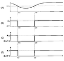
- variable valve system 10 changes in the state of the vehicle equipped with the variable valve system 10 are shown by five time charts.
- A shows the change over time of the voltage of driving power supplied to the control unit 100 (hereinafter referred to as “power supply voltage”).
- B the time change of the operation state (ON or OFF) of the control part 100 is shown.
- C shows a change in the calculation state of the crank angle (whether it can be calculated or cannot be calculated).
- D shows a change in the cam angle calculation status (can be calculated or cannot be calculated).
- FIG. 4 five time charts are shown as in FIG. In FIG. 4, what is indicated by (A), (B), (C), (D), and (E) is the same as that shown in the time charts of FIG. It is.
- FIG. 2 shows a change in the state of the vehicle when the power supply voltage is temporarily lowered and the control unit 100 is reset accordingly.
- the threshold value VTH shown in FIG. 2A is a minimum power supply voltage at which the control unit 100 can stably operate.
- the power supply voltage decreases and falls below the threshold value VTH at time t10, and then the power supply voltage exceeds the threshold value VTH again at time t20.
- Such a temporary drop in the power supply voltage may occur, for example, at the start of the internal combustion engine at a low temperature, that is, at the time of cranking when power is consumed for warm-up. It may also occur when the battery mounted on the vehicle deteriorates.
- the power supply voltage is higher than the threshold value VTH (FIG. 2A), and the control unit 100 is operating normally (FIG. 2B).
- the crank angle is calculated based on the pulse from the crank angle sensor 240 (FIG. 2C), and the crank angle is also calculated based on the voltage signal from the cam angle sensor 340. (FIG. 2D).
- the control unit 100 starts operating again (FIG. 2B). That is, it can be said that the control unit 100 is temporarily in a reset state due to temporarily unstable power supply in the period from time t10 to time t20.
- the crankshaft 200 rotates as cranking of the internal combustion engine is performed, and a pulse is input to the control unit 100 from the crank angle sensor 240.
- the controller 100 cannot recognize the absolute value of the crank angle until the missing tooth portion of the detected object 230 passes the crank angle sensor 240. That is, the crank angle is not fixed.
- the time when the missing tooth portion of the detection object 230 first passes through the crank angle sensor 240 is indicated as “time t30”. Since the crank angle is fixed after time t30, the control unit 100 can calculate the crank angle (FIG. 2C).
- the control unit 100 After time t20, the control unit 100 receives a voltage signal from the cam angle sensor 340. Unlike the crank angle sensor 240, since the cam angle sensor 340 is an absolute angle sensor, the control unit 100 can immediately calculate the cam angle based on the voltage signal. That is, the cam angle can be calculated by the control unit 100 after time t20 (FIG. 2D).
- both the calculation of the crank angle by the control unit 100 and the calculation of the cam angle by the control unit 100 can be performed.
- the controller 100 calculates (measures) the cam angle based on the voltage signal from the cam angle sensor 340 at the same time (time t30) when the rotation angle of the crankshaft 200 is determined.
- the control unit 100 calculates the cam angle phase based on the current crank angle and cam angle values. Thereafter, start-up control of the internal combustion engine including control (cam shaft phase control) for matching the cam angle phase with the target value is started.
- the startup control includes ignition control that adjusts ignition (ignition timing and ignition energy) in the internal combustion engine.
- the injection control which adjusts fuel injection is also included.
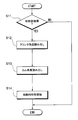
- FIG. 3 is a flowchart showing a flow of processing executed when the control unit 100 is activated (when returning from the reset state).
- step S01: NO If the control unit 100 is not activated (step S01: NO), the series of processing shown in FIG. 3 is not performed.
- step S01: YES the process proceeds from step S01 to step S02.
- step S02 calculation of the crank angle is attempted based on the pulse input from the crank angle sensor 240. At this time, if the missing tooth portion of the detected object 230 is before passing the crank angle sensor 240, the pulse is counted, but the crank angle is not fixed. After the missing tooth portion of the detection object 230 passes through the crank angle sensor 240, the crank angle is determined, and an accurate crank angle is calculated.
- step S03 it is determined whether or not the crank angle is fixed as described above. If the crank angle is fixed, the process proceeds to step S04. If the crank angle has not been determined, the process of step S02 is executed again. The period in which the crank angle is not fixed and the process of step S02 is repeatedly executed corresponds to the period from time t20 to time t30 in FIG.
- step S04 the crank angle is fixed and the cam angle can be calculated.
- step S04 the cam angle is calculated (measured) based on the voltage signal from the cam angle sensor 340. Thereafter, as described above, the start-time control is started (step S05).
- variable valve system 10 after returning from the reset state, the rotation angle of the crankshaft 200 is determined (the missing tooth position is detected by cranking) and at the same time, the camshaft 300 The rotation angle is measured, and subsequently, control of the internal combustion engine is started. As a result, appropriate control of the opening / closing timing of the intake valve can be started within a relatively short period of time.
- control unit 100 is reset as the power supply voltage is reduced.
- the cause of the reset may be other than a decrease in the power supply voltage.
- the control described above is performed even after the control unit 100 is reset due to battery replacement or internal combustion engine recombination.
- control is also performed at the time of normal starting immediately after the ignition switch of the vehicle is turned on.
- variable valve system (not shown) according to the second embodiment of the present disclosure will be described.
- the crank angle sensor 240 of the variable valve system 10 shown in FIG. 1 is replaced with an absolute angle sensor similar to the cam angle sensor 340.
- the detected object 230 of the crankshaft 200 is replaced with one having the same configuration as the detected object 330, and the crank angle sensor 240 is replaced with a gap sensor similar to the cam angle sensor 340.
- the control unit 100 calculates the absolute value of the crank angle based on the value of the voltage signal input from the crank angle sensor 240.
- FIG. 4 shows changes in the state of the vehicle equipped with the variable valve system 10 according to the second embodiment. Also in the present embodiment, in the period from time t10 to time t20 when the control unit 100 is OFF (reset state), calculation of the crank angle by the crank angle sensor 240, calculation of the cam angle by the cam angle sensor 340, Neither calculation nor control of the cam angle phase based on these is performed.
- control unit 100 When the control unit 100 returns from the reset state at time t20, the control unit 100 starts the start-time control. Also in the present embodiment, in order to perform the start-up control, the control unit 100 needs to grasp the current crank angle and cam angle.
- crank angle sensor 240 is configured as an absolute angle sensor. Therefore, an accurate crank angle sensor can be calculated (measured) immediately at time t20 (without waiting for missing teeth to pass by cranking) without waiting for the crank angle to be determined after time t20. (FIG. 3C).
- crank angle and the cam angle are both calculated after time t20, the calculation and control of the cam angle phase is started based on these.
- the state of the vehicle after the cam angle phase control is started at time t20 is the same as the state of the vehicle after time t30 in FIG.
- FIG. 5 is a flowchart showing a flow of processing executed when the vehicle is started.
- step S11: NO If the control unit 100 is not activated (step S11: NO), the series of processes shown in FIG. 5 is not performed.
- step S11: YES the process proceeds from step S11 to step S12.
- step S12 the crank angle is calculated (measured) based on the voltage signal from the crank angle sensor 240.
- step S13 the cam angle is calculated (measured) based on the voltage signal from the cam angle sensor 340.
- step S05 the current cam angle phase is calculated based on the crank angle and the cam angle, and the starting control is started.
- the crank angle sensor 240 is configured as an absolute angle sensor that measures the absolute rotation angle of the crankshaft 200. That is, both the crank angle sensor 240 and the cam angle sensor 340 are configured as absolute angle sensors. For this reason, it is possible to immediately start the control of the internal combustion engine without waiting for the determination of the rotation angle of the crankshaft 200 after returning from the reset state.
- the cam angle phase may be changed not by a rotating electrical machine such as the motor 400 but by an operation of a hydraulic mechanism.
- the absolute angle sensor is not limited to the method of detecting the gap, but may be a method of detecting the rotation angle by other means.
Landscapes
- Engineering & Computer Science (AREA)
- Mechanical Engineering (AREA)
- General Engineering & Computer Science (AREA)
- Chemical & Material Sciences (AREA)
- Combustion & Propulsion (AREA)
- Output Control And Ontrol Of Special Type Engine (AREA)
- Valve Device For Special Equipments (AREA)
- Combined Controls Of Internal Combustion Engines (AREA)
Abstract
可変バルブシステム(10)は、クランク軸(200)の回転角度を測定するクランク角センサ(240)と、クランク軸(200)に連動しバルブを開閉させるカム軸(300)、の回転角度を測定するカム角センサ(340)と、内燃機関の制御を行う制御部(100)と、を備える。カム角センサ(340)は、カム軸(300)の絶対的な回転角度を測定する絶対角センサとして構成されている。リセット状態から復帰した際において、制御部(100)は、クランク軸(200)軸の回転角度が確定すると同時に、カム角センサ(340)によりカム軸(300)の回転角度を測定し、その後、内燃機関の制御を開始する。
Description
本出願は、当該開示内容が参照によって本出願に組み込まれた、2015年3月26日に出願された日本特許出願2015-65145を基にしている。
本開示は、内燃機関におけるバルブの開閉タイミングを変化させる可変バルブシステムに関する。
内燃機関は吸気バルブ及び排気バルブを備えている。それぞれのバルブの開閉は、内燃機関のクランク軸の回転に同期して適切なタイミングで行われる。具体的には、クランク軸が回転すると、これに連動してカム軸が回転し、当該カム軸に設けられた複数のカムがそれぞれのバルブを開閉させる構成となっている。
バルブの開閉タイミング、すなわち、バルブの開閉が行われる際におけるクランク角度が常に一定であったとしても、内燃機関を動作させることは可能である。しかしながら、バルブの最適な開閉タイミングは常に同じではなく、内燃機関の運転状況(回転数やトルクなど)によって変化することが知られている。
このため、運転状況に応じてバルブの開閉タイミングを変化させることのできるシステム、すなわち可変バルブシステムが開発されており、既に実用化されている。可変バルブシステムは、クランク軸の回転角度(クランク角度)と、カム軸の回転角度(カム角度)との関係、すなわち、クランク軸に対するカム軸の相対的な回転角度であるカム軸位相を変化させることにより、吸気バルブ及び排気バルブのうち少なくとも一方の開閉タイミングを変化させるものである(例えば下記特許文献1を参照)。
可変バルブシステムでは、バルブの開閉タイミングを適切なものとするための制御を行うにあたり、上記のカム軸位相を目標値に一致させる必要がある。このため、クランク角度を測定するためのセンサと、カム角度を測定するためのセンサとをそれぞれ備えており、これらセンサの測定値に基づいて現時点におけるカム軸位相を算出している。
上記特許文献1に記載されている可変バルブシステムでは、クランク角度を測定するためのセンサとして、クランク軸の回転に伴って生じるパルスの数をカウントし、これによりクランク角度を測定する方式のセンサが用いられている。また、カム角度を測定するためのセンサとして、カム軸の回転に伴って生じるパルスの数をカウントし、これによりカム角度を測定する方式のセンサが用いられている。
このような方式のセンサは、カム軸等の絶対的な回転角度(カム角度等の絶対値)を直接測定するものではなく、特定の状態からのカム角度等の変化量を測定するものである。このため、パルスの数をカウントし続けている限りにおいては、カム角度等の絶対値を測定することができる。
しかしながら、例えば車両のバッテリ電圧が一時的に低下し、これにより制御部のリセットが生じたような場合には、カム角度等の絶対値の情報が失われてしまうこととなる。このような場合において、カム角度等の測定を再開するためには、カム軸等の絶対的な回転角度を確定し得る状態となるまでクランク軸やカム軸を回転させる必要がある。「カム軸等の絶対的な回転角度を確定し得る状態」とは、例えば、特定のクランク角度(例えば0°)に対応して予め形成された欠け歯(生じるパルスの間隔が他と異なる部分)が、クランク角センサにより検知された状態のことである。
このように、リセット状態からの復帰時には、しばらくの間はカム角度等の絶対値が不明な状態となるので、現時点におけるカム軸位相を算出することができず、バルブの開閉タイミングを適切に制御することができない恐れがある。このため、内燃機関の制御(例えば、点火タイミングや点火エネルギーを調整する点火制御)が開始されるまでに、無駄な待ち時間が生じる恐れがある。
本開示の目的は、制御部がリセット状態から復帰した後、バルブの開閉タイミングの適切な制御を短期間のうちに開始することのできる可変バルブシステムを提供することにある。
本開示に係る可変バルブシステムは、内燃機関におけるバルブの開閉タイミングを変化させる可変バルブシステムであって、内燃機関のクランク軸の回転角度を測定するクランク角測定部と、クランク軸に連動しバルブを開閉させるカム軸、の回転角度を測定するカム角測定部と、内燃機関の制御を行う制御部と、を備える。カム角測定部は、カム軸の絶対的な回転角度を測定する絶対角センサとして構成されている。制御部がリセット状態から復帰した際において、制御部は、クランク軸の回転角度が確定すると同時に、カム角測定部によりカム軸の回転角度を測定し、その後、内燃機関の制御を開始する。
このような構成の可変バルブシステムでは、カム軸の回転角度を測定するカム角測定部が、カム軸の絶対的な回転角度を測定する絶対角センサとして構成されている。このため、制御部がリセット状態から復帰した時点では、少なくともカム軸の絶対的な回転角度を測定することが可能な状態となっている。
そこで、本開示では、リセット状態からの復帰後、クランク軸の回転角度が確定する(クランキングにより欠け歯位置が検出される)と同時にカム軸の回転角度を測定し、これに続いて内燃機関の制御を開始する。その結果、バルブの開閉タイミングの適切な制御を比較的短期間のうちに開始することができる。
より好ましくは、クランク角測定部が、クランク軸の絶対的な回転角度を測定する絶対角センサとして構成されていてもよい。つまり、クランク角測定部とカム角測定部との両方が絶対角センサとして構成されていてもよい。この場合、リセット状態からの復帰後、クランク軸の回転角度の確定を待つことなく直ちに内燃機関の制御を開始することができる。
本開示によれば、制御部がリセット状態から復帰した後、バルブの開閉タイミングの適切な制御を短期間のうちに開始することのできる可変バルブシステムが提供される。
以下、添付図面を参照しながら本開示の実施形態について説明する。説明の理解を容易にするため、各図面において同一の構成要素に対しては可能な限り同一の符号を付して、重複する説明は省略する。
第1実施形態に係る可変バルブシステム10は、不図示の内燃機関を備えた車両に搭載されており、当該内燃機関における吸気バルブの開閉タイミングを変化させるためのものである。尚、上記構成はあくまで一例であって、可変バルブシステム10は、排気バルブの開閉タイミングを変化させるものであってもよい。また、吸気バルブ及び排気バルブのそれぞれの開閉タイミングを個別に変化させるものであってもよい。
図1を参照しながら、上記車両の構成について説明する。尚、図1においては、当該車両のうち、後述の可変バルブシステム10の構成及び動作を説明するために関する部分が図示されている。車両は、内燃機関の駆動力により回転するクランク軸200と、クランク軸200に連動して回転するカム軸300とを備えている。
クランク軸200には、プーリー210と、被検出体230とが設けられている。プーリー210は略円板状の回転体であって、その主面の中心をクランク軸200が垂直に貫いている。プーリー210はクランク軸200に対して固定されており、クランク軸200が回転すると、それに伴ってプーリー210も回転する。
プーリー210の外周面にはタイミングチェーン250が掛けられている。プーリー210の回転、すなわちクランク軸200の回転は、タイミングチェーン250を介して可変バルブシステム10(後述のアウターギヤ320)に伝達され、可変バルブシステム10を介してカム軸300に伝達される。
被検出体230は略円板状の回転体であって、その主面の中心をクランク軸200が垂直に貫いている。被検出体230はクランク軸200に対して固定されており、クランク軸200が回転すると、それに伴って被検出体230も回転する。
被検出体230は、クランク軸200の回転角度(以下、「クランク角度」とも表記する)を、可変バルブシステム10の一部であるクランク角センサ240が検知するためのものである。被検出体230の外周には複数の突起が等間隔で並ぶよう形成されている。ただし、突起の間隔は全てが同じなのではなく、一箇所だけ他とは異なっている。
クランク角センサ240は、被検出体230の外周面に対向するように設けられている。クランク軸200及び被検出体230が回転すると、被検出体230は、その近傍を被検出体230の突起が通過する毎に電圧のパルスを発生させる。当該パルス、すなわちクランク角度の測定値を示す信号は、制御部100に入力される。制御部100は、当該パルスをカウントすることによりクランク角度を計測する。すなわち、クランク角センサ240は、クランク角測定部に相当する。
被検出体230に形成された突起の間隔が他と異なっている部分(以下、「欠け歯箇所」とも称する)がクランク角センサ240を通過したとき、すなわち、一定であったパルスの間隔が変化したことが検知されたときに、制御部100は、クランク角度が特定の値(例えば0°)になったと認識する。このように、被検出体230の外周に形成された欠け歯箇所は、制御部100がクランク角度の絶対値を認識する(確定させる)ためのものとして機能する。
カム軸300は、吸気バルブを開閉させるためのカム(不図示)が取り付けられたシャフトである。カム軸300は、クランク軸200の回転に連動して回転し、これに伴うカムの動きによって吸気バルブを開閉させる。
カム軸300には、可変バルブシステム10の一部であるインナーギヤ310と、被検出体330とが設けられている。インナーギヤ310は略円板状の回転体であって、その主面の中心をカム軸300が垂直に貫いている。インナーギヤ310はカム軸300に対して固定されており、インナーギヤ310が回転すると、それに伴ってカム軸300も回転する。後に詳しく説明するように、可変バルブシステム10は、クランク軸200の回転を、インナーギヤ310を介してカム軸300に伝達し、これによりカム軸300を回転させるものである。
被検出体330は略円板状(ただし真円ではない)の回転体であって、その主面の中心をカム軸300が垂直に貫いている。被検出体330はカム軸300に対して固定されており、カム軸300が回転すると、それに伴って被検出体330も回転する。
被検出体330は、カム軸300の回転角度(以下、「カム角度」とも表記する)を、可変バルブシステム10の一部であるカム角センサ340が検知するためのものである。
カム角センサ340は、被検出体330の外周面に対向するように設けられている。被検出体330の主面は真円とはなっていない。このため、カム軸300及び被検出体330が回転すると、カム角センサ340と被検出体330の外周面との間の隙間は、回転に伴って次第に変化する。
被検出体330の形状は、カム軸300の回転角度の値(0°~360°)と上記隙間の大きさとの関係が1対1となるように設定されている。また、カム角センサ340は、所謂ギャップセンサとして構成されており、上記隙間の大きさに応じた電圧信号を出力する。つまり、カム角センサ340は、カム角度の絶対値を測定することのできるセンサ(絶対角センサ)となり、カム角測定部に相当する。上記電圧信号、すなわちカム角度の測定値(絶対値)を示す信号は、制御部100に入力される。
以上のように、内燃機関のクランク軸200が回転すると、当該回転がタイミングチェーン250及び可変バルブシステム10を介してカム軸300に伝達され、これによりカム軸300が回転する。このような構成の車両においては、吸気バルブの開閉タイミング、すなわち、吸気バルブの開閉が行われる際におけるクランク角度は、クランク軸200に対するカム軸300の相対的な回転角度(以下、「カム軸位相」と表記する)により定まることとなる。可変バルブシステム10は、カム軸位相を変化させることにより、吸気バルブの開閉タイミングを変化させるものである。
図1に模式的に示されるように、可変バルブシステム10は、インナーギヤ310と、アウターギヤ320と、遊星ギヤ420と、モーター400と、支持軸410と、制御部100と、を備えている。
インナーギヤ310は、既に述べたようにカム軸300に固定されており、カム軸300と一体となって回転するものである。インナーギヤ310の外周面には、後述の遊星ギヤ420と噛み合う外歯(不図示)が形成されている。
アウターギヤ320は、クランク軸200と同期して回転するスプロケット(不図示)の一部をなすリング状の部材である。アウターギヤ320は、その中心軸をカム軸300の中心軸と一致させた状態で配置されている。アウターギヤ320(スプロケット)の外周面にはタイミングチェーン250が掛けられている。このため、クランク軸200及びプーリー210が回転すると、当該回転がタイミングチェーン250を介してアウターギヤ320に伝達され、これによりアウターギヤ320が回転する。アウターギヤ320の内周面には、遊星ギヤ420と噛み合う内歯(不図示)が形成されている。
遊星ギヤ420は、インナーギヤ310の外歯、及びアウターギヤ320の内歯の両方に噛み合った状態で配置された円形の歯車である。遊星ギヤ420は、後述のモーター400及び支持軸410により、インナーギヤ310の外周面に沿って円軌道を描くように旋回することが可能となっている。
モーター400は、電力の供給を受けて動作する回転電機である。モーター400は、インナーギヤ310の外周面に沿って遊星ギヤ420を旋回させるためのものである。モーター400の回転速度は、制御部100により制御される。また、モーター400は、その回転軸(出力軸)の回転角度が所定量(例えば10°)変化する毎に、パルス状の電圧信号を制御部100に向けて出力する。このような電圧信号は、モーター400に内蔵されたホールセンサ(不図示)により生じる。
支持軸410は、モーター400と遊星ギヤ420と接続するものである。支持軸410は、回転部411と、連結部412と、支持部413とを有している。
回転部411は、モーター400の回転軸と一体となっている部分であって、その中心軸をカム軸300の中心軸と一致させた状態で配置されている。連結部412は、回転部411の端部(モーター400とは反対側の端部)から、回転部411の中心軸に対して垂直に伸びるように形成された部分である。支持部413は、連結部412の端部(回転部411とは反対側の端部)から、回転部411の中心軸に対して平行に伸びるように形成された部分である。支持部413の端部(連結部412とは反対側の端部)は、遊星ギヤ420に接続されている。遊星ギヤ420は、支持部413の中心軸周りに回転自在な状態で、支持部413の端部に取り付けられている。
既に述べたように、モーター400の回転速度は制御部100により制御される。モーター400の回転速度、すなわち、遊星ギヤ420の旋回速度がアウターギヤ320(スプロケット)の回転速度と同じである場合には、インナーギヤ310及びカム軸300の回転速度はアウターギヤ320の回転速度と同じである。このような状態においては、カム軸位相の値は一定であるから、吸気バルブの開閉タイミングも常に一定となる。
一方、モーター400の回転速度が変化し、遊星ギヤ420の旋回速度がアウターギヤ320の回転速度と異なっているときには、カム軸位相が変化する。その結果、吸気バルブの開閉タイミングが変化する。
その後、モーター400の回転速度が再びアウターギヤ320の回転速度と同じになると、カム軸位相は再び一定の値(ただし、モーター400の回転速度が変化する前とは異なる値である)となり、吸気バルブの開閉タイミングも再び一定となる。このように、モーター400の回転速度を、アウターギヤ320の回転速度とは一時的に異ならせることでカム軸位相を変化させ、これにより吸気バルブの開閉タイミングを変化させることが可能となっている。
制御部100は、可変バルブシステム10の全体の動作、及び内燃機関の動作を制御するものである。制御部100は、CPU、RAM、ROM、インターフェース等を備えたコンピュータシステムとして構成されている。
制御部100は、モーター400の回転速度を制御し、これによりカム軸位相を目標値に一致させる。具体的には、クランク角センサ240から入力されるパルスに基づいてクランク角度を算出し、カム角センサ340から入力される電圧信号に基づいてカム角度を算出する。その後、クランク角度とカム角度との差分に基づいて、現時点におけるカム軸位相を算出する。算出されたカム軸位相をフィードバックしながら、当該カム軸位相が目標値に一致するよう、モーター400の回転速度を制御する。
可変バルブシステム10の動作について、図2を参照しながら説明する。図2には、可変バルブシステム10を搭載した車両の状態の変化が、5つのタイムチャートにより示されている。これら5つのタイムチャートのうち、(A)には、制御部100に供給される駆動用電力の電圧(以下、「電源電圧」という)の時間変化が示されている。(B)には、制御部100の作動状態(ON又はOFF)の時間変化が示されている。(C)には、クランク角度の算出状況(算出可能か、それとも算出不可能か)の変化が示されている。(D)には、カム角度の算出状況(算出可能か、それとも算出不可能か)の変化が示されている。
尚、後に説明する図4においても、図2と同様に5つのタイムチャートが示されている。図4において(A),(B),(C),(D),(E)により示されるものは、上記の図2の各タイムチャートで示されるもの(電源電圧の時間変化等)と同じである。
図2には、電源電圧が一時的に低下し、これに伴って制御部100のリセットが生じた場合における、車両の状態の変化が示されている。図2(A)に示される閾値VTHは、制御部100が安定的に動作し得る最低限の電源電圧である。図2の例では、電源電圧が低下して時刻t10において閾値VTHを下回り、その後、時刻t20において再び電源電圧が閾値VTHを上回っている。
このような一時的な電源電圧の低下は、例えば低温時における内燃機関の始動時、すなわち、暖機のために電力が消費されているときのクランキング時において生じることがある。また、車両に搭載されたバッテリが劣化したときにおいても生じることがある。
時刻t10よりも前の期間においては、電源電圧は閾値VTHを上回っており(図2(A))、制御部100は正常に動作している(図2(B))。また、同期間においてはクランク角センサ240からのパルスに基づくクランク角度の算出が行われており(図2(C))、カム角センサ340からの電圧信号に基づくクランク角度の算出も行われている(図2(D))。
一方、時刻t10以降は、電源電圧が閾値VTHを下回り(図2(A))、これに伴って制御部100はその動作を停止した状態となる(図2(B))。このため、制御部100によるクランク角度の算出を行うことはできなくなっており(図2(C))、制御部100によるカム角度の算出を行うこともできなくなっている(図2(D))。
時刻t20において再び電源電圧が閾値VTHを上回ると(図2(A))、制御部100は再び動作を開始する(図2(B))。つまり、時刻t10から時刻t20までの期間において一時的に電力供給が不安定になることにより、制御部100は一時的にリセット状態となった、ということができる。
時刻t20以降、内燃機関のクランキングが行われることに伴ってクランク軸200が回転し、制御部100にはクランク角センサ240からパルスが入力される。しかしながら、被検出体230の欠け歯箇所がクランク角センサ240を通過するまでの間は、制御部100がクランク角度の絶対値を認識することができない。すなわち、クランク角度が確定しない。図2では、被検出体230の欠け歯箇所がクランク角センサ240を最初に通過した時刻が「時刻t30」として示されている。時刻t30以降はクランク角度が確定しているので、制御部100によるクランク角度の算出を行うことが可能となっている(図2(C))。
時刻t20以降、制御部100にはカム角センサ340から電圧信号が入力される。クランク角センサ240と異なり、カム角センサ340は絶対角センサであるから、制御部100は電圧信号に基づいて直ちにカム角度の算出を行うことができる。つまり、時刻t20以降は、制御部100によるカム角度の算出を行うことが可能となっている(図2(D))。
以上のように、時刻t20より後の時刻t30以降においては、制御部100によるクランク角度の算出、及び制御部100によるカム角度の算出、の両方を行うことが可能となっている。制御部100は、クランク軸200の回転角度が確定すると同時(時刻t30)に、カム角センサ340からの電圧信号に基づいてカム角度を算出(測定)する。
時刻t30以降、制御部100は、現時点におけるクランク角度及びカム角度のそれぞれの値に基づいてカム角位相を算出する。その後、カム角位相を目標値に一致させる制御(カム軸位相制御)を含む、内燃機関の始動時制御が開始される。始動時制御には、内燃機関における点火(点火タイミングや点火エネルギー)を調整する点火制御も含まれる。また、燃料噴射を調整する噴射制御も含まれる。
図2に示されるような動作を実現するために、制御部100で行われる処理の具体的な内容について、図3を参照しながら説明する。図3は、制御部100の起動時(リセット状態からの復帰時)において実行される処理の流れを示すフローチャートである。
制御部100が起動されていなければ(ステップS01:NO)、図3に示される一連の処理は行われない。制御部100がリセット状態から復帰して起動された状態になると(ステップS01:YES)、ステップS01からステップS02に移行する。
ステップS02では、クランク角センサ240から入力されるパルスに基づいて、クランク角度の算出が試みられる。このとき、被検出体230の欠け歯箇所がクランク角センサ240を通過するよりも前であれば、パルスのカウントは行われるのであるが、クランク角度は確定していない。被検出体230の欠け歯箇所がクランク角センサ240を通過した後は、クランク角度が確定しており、正確なクランク角度が算出されるようになる。
ステップS02に続くステップS03では、クランク角度が上記のように確定しているか否かが判定される。クランク角度が確定していればステップS04に移行する。クランク角度が確定していなければ、ステップS02の処理が再度実行される。クランク角度が確定しておらず、ステップS02の処理が繰り返し実行されている期間は、図2(C)における時刻t20から時刻t30までの期間に相当する。
ステップS04に移行した時点(図2(C)における時刻t30)では、クランク角度が確定しており、且つカム角度を算出することも可能な状態となっている。ステップS04では、カム角センサ340からの電圧信号に基づいてカム角度が算出(測定)される。以降は、既に述べたように始動時制御が開始される(ステップS05)。
以上のように、本実施形態に係る可変バルブシステム10では、リセット状態からの復帰後、クランク軸200の回転角度が確定する(クランキングにより欠け歯位置が検出される)と同時にカム軸300の回転角度を測定し、これに続いて内燃機関の制御を開始する。これにより、吸気バルブの開閉タイミングの適切な制御を比較的短期間のうちに開始することが可能となっている。
尚、以上においては、電源電圧の低下に伴って制御部100のリセットが生じた場合について説明した。しかしながら、リセットの生じる原因は、電源電圧の低下以外であってもよい。例えば、バッテリの交換や内燃機関の組み換えに伴って制御部100がリセットされた後においても、上記のような制御が行われる。また、車両のイグニッションスイッチがON状態とされた直後の通常の始動時においても、上記のような制御が行われる。
本開示の第2実施形態に係る可変バルブシステム(図示省略)について説明する。第2実施形態は、図1に示される可変バルブシステム10のクランク角センサ240を、カム角センサ340と同様の絶対角センサに置き換えたものである。具体的には、クランク軸200の被検出体230を被検出体330と同様の構成のものに置き換えて、クランク角センサ240をカム角センサ340と同様のギャップセンサに置き換えたものである。第2実施形態における制御部100は、クランク角センサ240から入力される電圧信号の値に基づいて、クランク角度の絶対値を算出する。
図4には、第2実施形態に係る可変バルブシステム10を搭載した車両の状態の変化が示されている。本実施形態においても、制御部100がOFF(リセット状態)となっている時刻t10から時刻t20までの期間においては、クランク角センサ240によるクランク角度の算出、カム角センサ340によるカム角度の算出、及びこれらに基づくカム角位相の算出及び制御は、いずれも行われない。
時刻t20において制御部100がリセット状態から復帰すると、制御部100は始動時制御を開始する。本実施形態においても、始動時制御を行うには、制御部100が現時点のクランク角度及びカム角度をそれぞれ把握している必要がある。
本実施形態においては、カム角センサ340のみならず、クランク角センサ240も絶対角センサとして構成されている。このため、時刻t20以降においてクランク角度が確定するのを待つことなく、時刻t20において直ちに(クランキングによる欠け歯の通過を待つことなく)正確なクランク角センサを算出(測定)することが可能となっている(図3(C))。
時刻t20以降、クランク角度及びカム角度がいずれも算出されるので、これらに基づいてカム角位相の算出及び制御が開始される。時刻t20でカム角位相制御が開始された以降における車両の状態は、図2の時刻t30以降における車両の状態と同じである。
図4に示されるような動作を実現するために、制御部100で行われる処理の具体的な内容について、図5を参照しながら説明する。図5は、車両の始動時において実行される処理の流れを示すフローチャートである。
制御部100が起動されていなければ(ステップS11:NO)、図5に示される一連の処理は行われない。制御部100がリセット状態から復帰して起動された状態になると(ステップS11:YES)、ステップS11からステップS12に移行する。
ステップS12に移行した時点(図4における時刻t20)では、クランク角度の算出及びカム角度の算出の両方を行うことが可能な状態となっている。ステップS12では、クランク角センサ240からの電圧信号に基づいてクランク角度が算出(測定)される。ステップS12に続くステップS13では、カム角センサ340からの電圧信号に基づいてカム角度が算出(測定)される。
以降は、クランク角度及びカム角度に基づいて現時点のカム角位相が算出され、始動時制御が開始される(ステップS05)。
以上のように、第2実施形態に係る可変バルブシステム10では、クランク角センサ240が、クランク軸200の絶対的な回転角度を測定する絶対角センサとして構成されている。つまり、クランク角センサ240とカム角センサ340との両方が絶対角センサとして構成されている。このため、リセット状態からの復帰後、クランク軸200の回転角度の確定を待つことなく直ちに内燃機関の制御を開始することが可能となっている。
以上においては、モーター400の駆動力によってカム角位相を変化させる構成について説明したが、本開示の実施態様はこのような構成に限定されない。例えば、モーター400のような回転電機ではなく、油圧機構の動作によってカム角位相を変化させる構成としてもよい。
また、絶対角センサもギャップを検出する方式に限らず、他の手段で回転角度を検出する方式としてもよい。
以上、具体例を参照しつつ本開示の実施の形態について説明した。しかし、本開示はこれらの具体例に限定されるものではない。すなわち、これら具体例に、当業者が適宜設計変更を加えたものも、本開示の特徴を備えている限り、本開示の範囲に包含される。例えば、前述した各具体例が備える各要素およびその配置、材料、条件、形状、サイズなどは、例示したものに限定されるわけではなく適宜変更することができる。また、前述した各実施の形態が備える各要素は、技術的に可能な限りにおいて組み合わせることができ、これらを組み合わせたものも本開示の特徴を含む限り本開示の範囲に包含される。
Claims (2)
- 内燃機関におけるバルブの開閉タイミングを変化させる可変バルブシステムであって、
前記内燃機関のクランク軸(200)の回転角度を測定するクランク角測定部(240)と、
前記クランク軸に連動し前記バルブを開閉させるカム軸(300)、の回転角度を測定するカム角測定部(340)と、
前記内燃機関の制御を行う制御部(100)と、を備え、
前記カム角測定部は、前記カム軸の絶対的な回転角度を測定する絶対角センサとして構成されており、
前記制御部がリセット状態から復帰した際において、前記制御部は、
前記クランク軸の回転角度が確定すると同時に、前記カム角測定部により前記カム軸の回転角度を測定し、その後、前記内燃機関の制御を開始する可変バルブシステム。 - 内燃機関におけるバルブの開閉タイミングを変化させる可変バルブシステムであって、
前記内燃機関のクランク軸の回転角度を測定するクランク角測定部と、
前記クランク軸に連動し前記バルブを開閉させるカム軸、の回転角度を測定するカム角測定部と、
前記内燃機関の制御を行う制御部と、を備え、
前記クランク角測定部は、前記クランク軸の絶対的な回転角度を測定する絶対角センサとして構成されており、
前記カム角測定部は、前記カム軸の絶対的な回転角度を測定する絶対角センサとして構成されており、
前記制御部がリセット状態から復帰した際において、前記制御部は、
前記クランク角測定部による前記クランク軸の回転角度の測定、及び、前記カム角測定部による前記カム軸の回転角度の測定をそれぞれ行い、その後、前記内燃機関の制御を開始する可変バルブシステム。
Applications Claiming Priority (2)
| Application Number | Priority Date | Filing Date | Title |
|---|---|---|---|
| JP2015065145A JP2016183645A (ja) | 2015-03-26 | 2015-03-26 | 可変バルブシステム |
| JP2015-065145 | 2015-03-26 |
Publications (1)
| Publication Number | Publication Date |
|---|---|
| WO2016152068A1 true WO2016152068A1 (ja) | 2016-09-29 |
Family
ID=56979057
Family Applications (1)
| Application Number | Title | Priority Date | Filing Date |
|---|---|---|---|
| PCT/JP2016/001382 Ceased WO2016152068A1 (ja) | 2015-03-26 | 2016-03-11 | 可変バルブシステム |
Country Status (2)
| Country | Link |
|---|---|
| JP (1) | JP2016183645A (ja) |
| WO (1) | WO2016152068A1 (ja) |
Cited By (2)
| Publication number | Priority date | Publication date | Assignee | Title |
|---|---|---|---|---|
| US10502101B2 (en) | 2015-03-27 | 2019-12-10 | Denso Corporation | Variable valve system |
| CN117583269A (zh) * | 2023-12-13 | 2024-02-23 | 南京拓曼思电气科技有限公司 | 一种快速检测smt贴片质量的装置及方法 |
Citations (5)
| Publication number | Priority date | Publication date | Assignee | Title |
|---|---|---|---|---|
| JP2007182864A (ja) * | 2006-01-10 | 2007-07-19 | Toyota Motor Corp | 内燃機関のバルブ特性制御装置 |
| JP2008019756A (ja) * | 2006-07-12 | 2008-01-31 | Hitachi Ltd | 内燃機関の可変動弁装置 |
| JP2008291769A (ja) * | 2007-05-25 | 2008-12-04 | Toyota Motor Corp | アクチュエータの制御装置 |
| JP2009185717A (ja) * | 2008-02-06 | 2009-08-20 | Yamaha Motor Co Ltd | 燃料噴射制御装置および車両 |
| JP2009533592A (ja) * | 2006-04-12 | 2009-09-17 | シエツフレル コマンディートゲゼルシャフト | カムシャフト調節装置用の同期装置及び方法及びメモリ媒体及びプログラム要素 |
-
2015
- 2015-03-26 JP JP2015065145A patent/JP2016183645A/ja active Pending
-
2016
- 2016-03-11 WO PCT/JP2016/001382 patent/WO2016152068A1/ja not_active Ceased
Patent Citations (5)
| Publication number | Priority date | Publication date | Assignee | Title |
|---|---|---|---|---|
| JP2007182864A (ja) * | 2006-01-10 | 2007-07-19 | Toyota Motor Corp | 内燃機関のバルブ特性制御装置 |
| JP2009533592A (ja) * | 2006-04-12 | 2009-09-17 | シエツフレル コマンディートゲゼルシャフト | カムシャフト調節装置用の同期装置及び方法及びメモリ媒体及びプログラム要素 |
| JP2008019756A (ja) * | 2006-07-12 | 2008-01-31 | Hitachi Ltd | 内燃機関の可変動弁装置 |
| JP2008291769A (ja) * | 2007-05-25 | 2008-12-04 | Toyota Motor Corp | アクチュエータの制御装置 |
| JP2009185717A (ja) * | 2008-02-06 | 2009-08-20 | Yamaha Motor Co Ltd | 燃料噴射制御装置および車両 |
Cited By (2)
| Publication number | Priority date | Publication date | Assignee | Title |
|---|---|---|---|---|
| US10502101B2 (en) | 2015-03-27 | 2019-12-10 | Denso Corporation | Variable valve system |
| CN117583269A (zh) * | 2023-12-13 | 2024-02-23 | 南京拓曼思电气科技有限公司 | 一种快速检测smt贴片质量的装置及方法 |
Also Published As
| Publication number | Publication date |
|---|---|
| JP2016183645A (ja) | 2016-10-20 |
Similar Documents
| Publication | Publication Date | Title |
|---|---|---|
| EP2518451B1 (en) | Abnormality determination device for rotation sensor | |
| US7980214B2 (en) | Control device for electrically driven variable valve timing apparatus | |
| JP4196294B2 (ja) | 内燃機関の可変バルブタイミング制御装置 | |
| JP4123005B2 (ja) | 内燃機関の可変バルブタイミング制御装置 | |
| JP4123127B2 (ja) | 内燃機関の可変バルブタイミング制御装置 | |
| CN100406699C (zh) | 内燃机的可变气门正时控制设备 | |
| CN101135269A (zh) | 用于内燃机的可变阀正时控制器 | |
| JP2006233914A5 (ja) | ||
| JP2009257186A (ja) | 可変バルブタイミング装置の制御装置 | |
| JP5573687B2 (ja) | 可変バルブタイミング制御システムのモータ回転状態検出系異常診断装置 | |
| JP4600935B2 (ja) | 内燃機関の可変バルブタイミング制御装置 | |
| WO2016152068A1 (ja) | 可変バルブシステム | |
| JP4641985B2 (ja) | 内燃機関の可変バルブタイミング制御装置 | |
| JP4267635B2 (ja) | 可変バルブタイミング装置 | |
| JP4868022B2 (ja) | モータ制御システムの異常判定装置 | |
| JP2002537518A (ja) | 点火制御装置および点火制御方法 | |
| JP6406091B2 (ja) | 可変バルブシステム | |
| JP6421672B2 (ja) | 可変バルブシステム | |
| JP6409645B2 (ja) | 可変バルブシステム | |
| JP2011094581A (ja) | 電動式可変バルブタイミング装置の制御装置 | |
| JP2017115626A (ja) | 車両用内燃機関 | |
| JP6520385B2 (ja) | 駆動制御装置 | |
| JP4444138B2 (ja) | 可変動弁機構の制御装置 | |
| JP2018066331A (ja) | 制御装置 | |
| JP4525579B2 (ja) | 内燃機関のバルブ特性制御装置 |
Legal Events
| Date | Code | Title | Description |
|---|---|---|---|
| 121 | Ep: the epo has been informed by wipo that ep was designated in this application |
Ref document number: 16767978 Country of ref document: EP Kind code of ref document: A1 |
|
| NENP | Non-entry into the national phase |
Ref country code: DE |
|
| 122 | Ep: pct application non-entry in european phase |
Ref document number: 16767978 Country of ref document: EP Kind code of ref document: A1 |