WO2016151955A1 - 耐熱部材の初期クリープ強度推定方法およびこの残寿命推定方法 - Google Patents
耐熱部材の初期クリープ強度推定方法およびこの残寿命推定方法 Download PDFInfo
- Publication number
- WO2016151955A1 WO2016151955A1 PCT/JP2015/084237 JP2015084237W WO2016151955A1 WO 2016151955 A1 WO2016151955 A1 WO 2016151955A1 JP 2015084237 W JP2015084237 W JP 2015084237W WO 2016151955 A1 WO2016151955 A1 WO 2016151955A1
- Authority
- WO
- WIPO (PCT)
- Prior art keywords
- heat
- resistant member
- creep strength
- carbide
- estimating
- Prior art date
- Legal status (The legal status is an assumption and is not a legal conclusion. Google has not performed a legal analysis and makes no representation as to the accuracy of the status listed.)
- Ceased
Links
Images



Classifications
-
- G—PHYSICS
- G01—MEASURING; TESTING
- G01N—INVESTIGATING OR ANALYSING MATERIALS BY DETERMINING THEIR CHEMICAL OR PHYSICAL PROPERTIES
- G01N3/00—Investigating strength properties of solid materials by application of mechanical stress
-
- G—PHYSICS
- G01—MEASURING; TESTING
- G01N—INVESTIGATING OR ANALYSING MATERIALS BY DETERMINING THEIR CHEMICAL OR PHYSICAL PROPERTIES
- G01N17/00—Investigating resistance of materials to the weather, to corrosion, or to light
Definitions
- the present invention relates to a method for estimating an initial creep strength of a heat-resistant member and a method for estimating this remaining life.
- Patent Document 1 stress based on hardness is used, data of a steady operation state is sequentially read from the operation result information storage unit, and based on this, the operation history calculation unit obtains member temperature and member stress, Calculate the amount of stress increase in each operating state, calculate the amount of creep strength decrease due to the stress increase, calculate the creep strength, obtain the current member hardness, and calculate the amount of creep strength decrease based on the planned operation state data.
- a life diagnosis method for a high temperature member that calculates a predicted value of a final creep strength after calculating a creep strength and calculates a remaining life based on the predicted value and planned operating conditions.
- the initial creep strength of the life evaluation target member is an important factor, but in the case of an aging plant, the initial creep strength of the member may not be grasped. In such a case, the remaining life of the device could not be accurately estimated. Therefore, it has been desired to estimate the initial creep strength and remaining life of existing members by a simple and rapid method.
- the present invention has been made to solve the above-described problems, and it is possible to quickly estimate the initial creep strength and remaining life of a heat-resistant member with a relatively simple operation.
- An object is to provide an initial creep strength estimation method and a remaining life estimation method.
- a method for estimating an initial creep strength of a heat-resistant member according to a first aspect of the present invention that solves the above-described problem is a method for estimating an initial creep strength of a heat-resistant member, wherein the heat-resistant member is subjected to a creep test at a predetermined temperature and stress.
- the breaking Larson mirror parameter is derived using the following relational expression (1): Creep of the heat-resistant member to obtain the creep strength diagram of the heat-resistant member based on the derivation step, the Larson mirror parameter at break, and the design creep strength diagram showing the relationship between the stress and the Larson mirror parameter in the heat-resistant member
- Equivalent average operating temperature estimation process for estimating the equivalent average operating temperature from the strength diagram acquisition step and the carbide state of the heat-resistant member
- a remaining life deriving step for deriving the remaining life of the heat-resistant member using the following relational expression (1) based on the creep strength diagram of the heat-resistant material and the equivalent average operating temperature; Based on the remaining life and the total life deriving step of deriving the total life of the heat resistant member based on the operation time of the heat resistant member, and the total life of the heat resistant member and the equivalent average operating temperature, the following relational expression (1 ) Using the design creep strength
- LMP T ⁇ (C + log (t)) / 1000
- T an absolute temperature (K)
- C a material constant of the heat-resistant member
- t an operation time of the heat-resistant member.
- the initial creep strength estimation method for a heat-resistant member according to the second invention for solving the above-described problem is an initial creep strength estimation method for the heat-resistant member according to the first invention, wherein the equivalent average operating temperature estimation step includes the steps Create a replica that transferred the surface texture of the heat-resistant member, create a carbide image based on the replica, derive the amount of carbide based on the carbide image, the carbide amount, the previously created carbide amount and Larson mirror parameters, The current Larson mirror parameter is derived using the master curve which is a correlation diagram of the above, and the equivalent average is calculated using the relational expression (1) based on the current Larson mirror parameter and the operation time of the heat-resistant member. The operation temperature is estimated.
- An initial creep strength estimation method for a heat-resistant member according to a third invention that solves the above-described problem is an initial creep strength estimation method for a heat-resistant member according to the second invention, wherein the carbide image is an image of a primary carbide. It is an image of a certain or secondary carbide, or an image of a primary carbide and a secondary carbide.
- An initial creep strength estimation method for a heat-resistant member according to a fourth aspect of the present invention that solves the above-described problem is an initial creep strength estimation method for a heat-resistant member according to the second or third aspect of the invention, wherein the amount of carbide is the amount of carbide. It is at least one of particle number density or carbide area ratio.
- An initial creep strength estimation method for a heat-resistant member according to a fifth invention for solving the above-described problem is an initial creep strength estimation method for a heat-resistant member according to any one of the second to fourth inventions, wherein The Larson mirror parameter is derived using the amount of carbide derived based on a carbide binarized image created by binarizing the carbide image and the master curve instead of the carbide image.
- a method for estimating an initial creep strength of a heat-resistant member according to a sixth invention that solves the above-described problem is a method for estimating an initial creep strength of a heat-resistant member according to any one of the first to fifth inventions, wherein the heat-resistant member Is a catalyst tube used for reforming natural gas.
- a method for estimating the remaining life of a heat-resistant member according to a seventh aspect of the present invention that solves the above-described problem is a method for estimating the remaining life of a heat-resistant member that estimates the remaining life of the heat-resistant member.
- the heat input received inside is derived as the Larson mirror parameter, and the equivalent average operating temperature is estimated using the following relational expression (2) based on the Larson mirror parameter of the current heat-resistant member and the known operation time.
- the equivalent average operating temperature, the initial creep strength of the heat-resistant member derived by the method of estimating the initial creep strength of the heat-resistant member according to any one of the first to fifth inventions, and the known operating stress.
- the total lifetime is derived, and the remaining lifetime is derived based on the total lifetime and the operation time of the heat-resistant member.
- LMP T ⁇ (C + log (t)) / 1000 (2)
- LMP is the Larson mirror parameter of the current heat-resistant member, T is the equivalent average operating temperature (absolute temperature (K)), and t is the operating time (total life).
- a method for estimating a remaining life of a heat-resistant member according to an eighth aspect of the present invention that solves the above-described problem is a method for estimating a remaining life of a heat-resistant member according to the seventh aspect, wherein the heat-resistant member is used for reforming natural gas. It is characterized by being a catalyst tube.
- FIG. 4A is a graph showing the relationship between the amount of carbide created in the procedure for deriving the remaining life and the Larson mirror parameter, and FIG. 4A shows the relationship between the particle number density of carbide and the Larson mirror parameter. b) shows the relationship between the area ratio of carbide and the Larson mirror parameter.
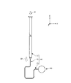
- the natural gas reformer includes, for example, a plurality of catalyst tubes 14 including a catalyst tube main body 11, a short piece 12, and a pigtail 13, as shown in FIG.
- the catalyst tube main body 11 is arranged upright so that the axis extends in the vertical direction.
- the short piece 12 is connected to the lower end portion of the catalyst tube main body 11, and is arranged upright so that the axis extends in the vertical direction.
- the pigtail 13 is connected to the lower end of the short piece 12, has a smaller diameter than the catalyst tube main body 11, and is bent.
- the other end of the pigtail 13 is connected to the hot collector 15.
- the hot collector 15 is arranged such that the axis extends in the horizontal direction (in the illustrated example, the front and back direction on the paper surface).
- the other end of the pigtail of the catalyst tube (not shown) is connected to the hot collector 15 at a position symmetrical to the catalyst tube 14. Further, a pair of left and right catalyst tubes connected to the hot collector 15 at a predetermined interval in the axial direction of the hot collector 15 are arranged.
- the natural gas reformer is provided with a plurality of hot collectors 15 to which a plurality of catalyst tubes 14 are connected.
- the catalyst tube main body 11, the short piece 12, and the pigtail 13 are made of, for example, HP-Nb-Ti (25Cr-35Ni-Nb, Ti) and Alloy 800H (Fe-32Ni-20Cr).
- the introduced mixed gas (methane gas, water vapor) 21 reacts to generate a product gas (hydrogen, water vapor, carbon monoxide, carbon dioxide) 22.
- This generated gas 22 is circulated to the hot collector 15 via the short piece 12 and the pigtail 13.
- the catalyst tube body 11 is placed in a furnace at about 900 ° C. or higher. Although the short piece 12 and the pigtail 13 are arranged outside the furnace, a gas of about 900 ° C. is circulated therein.
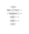
- the method for estimating the initial creep strength of the heat-resistant member includes a heat-resistant member creep test (obtaining the rupture time at the test temperature and stress) step S1 and a Larson Miller parameter derivation step when the heat-resistant member breaks S2, creep strength diagram acquisition step S3 of heat-resistant member, equivalent average operating temperature estimation step S4, remaining life derivation step S5, full lifetime derivation step S6, full lifetime Larson mirror parameter derivation step S7, initial creep And an intensity diagram deriving step S8.
- the rupture time of the catalyst tube main body 11 (aged heat-resistant member of the actual machine) extracted from the plant is acquired.
- a predetermined stress for example, XMPa
- a predetermined temperature for example, 900 ° C.
- the Larson mirror parameter (Larsson mirror parameter at break) when the rupture time is obtained in the heat-resistant member creep test step S1 is derived.
- the Larson Miller parameter at break is derived using the following relational expression (3). Is done.
- the Larson Miller parameter (LMP) satisfies the relationship of the following equation.
- LMP T ⁇ (C + log (t)) / 1000 (3)
- T is a temperature (absolute temperature (K)) at the time of a creep test of the catalyst tube main body 11 to be estimated
- C is a material constant of the catalyst tube main body 11 to be estimated
- t is a catalyst tube to be estimated. This is the operation (use) time of the main body 11.
- the Larson mirror parameter deriving step S2 when the heat-resistant member breaks the break time acquired in the heat-resistant member creep test step S1 is used as t.
- the equivalent average operation temperature estimation step S4 the equivalent average operation temperature of the catalyst tube main body 11 subjected to the above test is estimated.
- the equivalent average operation temperature estimation method includes a replica creation step S11, a carbide image creation step S12, an image adjustment step S13, a carbide amount derivation step S14, and a current Larson mirror parameter derivation step S15. And an equivalent average operating temperature estimation step S16.
- replica creation step S11 a replica is created by a conventional replica method.
- a replica in which the surface texture of the catalyst tube main body 11 is transferred is created.
- a film is preferably used as the replica.
- a carbide image (carbide image) is created from the replica (film) to which the surface structure of the catalyst tube main body 11 obtained in the replica creation step S11 is transferred.
- the carbide image is preferably a primary carbide image (primary carbide image) or a secondary carbide image (secondary carbide image), and more preferably both of these images. This is because the use temperature of the catalyst tube main body 11, which will be described later in detail, can be more reliably estimated.
- Each image is created by conventional image editing software.
- Primary carbide is a carbide that crystallizes along a dendrite boundary during solidification.
- the secondary carbide is a precipitate that is dispersed and precipitated in the grains with high temperature aging.
- the carbide image created in the carbide image creation step S12 is adjusted to create an image from which carbide can be easily extracted.
- the primary carbide image is adjusted to create an image from which primary carbide can be easily extracted.
- the carbide image is a secondary carbide image
- the secondary carbide image is adjusted to create an image from which secondary carbide can be easily extracted.
- a method of adjusting the carbide image it is preferable to use a binarization process.
- the primary carbide image is binarized to create a primary carbide binarized image.
- the secondary carbide image is binarized to create a secondary carbide binarized image.
- a carbide from a carbide binarized image (a primary carbide binarized image, a secondary carbide binarized image)) obtained by binarizing the carbide image (primary carbide image, secondary carbide image) Extraction of primary carbide and secondary carbide) becomes easy.
- the carbide amount derivation step S14 the carbide amount is derived based on the image obtained in the image adjustment step S13.
- the image obtained in the image adjustment step S13 is a primary carbide binarized image
- the amount of primary carbide is derived based on the primary carbide binarized image.
- the image obtained in the image adjustment step S13 is a secondary carbide binarized image
- the amount of secondary carbide is derived based on the secondary carbide binarized image.
- the amount of primary carbide is derived based on the primary carbide binarized image
- the binary A secondary carbide amount is derived based on the secondary carbide binarized image.
- the image obtained in the image adjustment step S13 is subjected to image analysis, the number of carbides is measured and converted per unit area, and the particle number density of the carbide obtained, or the image obtained in the image adjustment step S13 is imaged. It is preferable to use the carbide area ratio obtained by analyzing and measuring the area of the carbide and converting per unit area, and more preferably using both the particle number density of the carbide and the area ratio of the carbide.
- the carbide amount derivation step S15 uses the correlation graph (master curve) of the Larson mirror parameters and the carbide amount (the particle number density of carbide, the area ratio of carbide) created in advance in the current Larson mirror parameter derivation step S15, the carbide amount derivation step The current Larson mirror parameter corresponding to the amount of carbide obtained in S14 (the particle number density of carbide and the area ratio of carbide) is acquired.
- carbonized_material amount it is preferable that it is the amount of the primary carbide mentioned above or the amount of secondary carbide
- the correlation graph (master curve) between the Larson mirror parameter and the particle number density of carbide prepared in advance is used.
- the current Larson mirror parameter corresponding to the particle number density of the carbide obtained in the carbide amount deriving step S14 is acquired.
- the carbide amount obtained in the carbide amount deriving step S14 is the carbide area ratio
- a correlation diagram (master curve) between the Larson mirror parameter and the carbide area ratio prepared in advance is used, as shown in FIG.
- the current Larson mirror parameter corresponding to the area ratio of the carbide obtained in the carbide amount deriving step S14 is acquired.
- the relational expression The T in (3) is estimated (derived) as an equivalent average operating temperature.
- the known operation time corresponds to the operation time of the catalyst tube main body 11 in the plant.
- the equivalent average operating temperature estimation step S16 the current Larson mirror parameter is substituted for LMP in the relational expression (3), and the known operation time is substituted for t in the relational expression (3). It will be.
- the remaining life deriving step S5 the remaining life of the catalyst tube main body 11 described above is derived.
- the above relational expression (3) based on the creep strength diagram of the heat-resistant member acquired in the creep strength diagram acquisition step S3 of the heat-resistant member and the equivalent average operating temperature derived in the equivalent average operating temperature estimation step S4 (S16)
- the operation (use) time t is obtained.
- This operation time t corresponds to the remaining life. Therefore, based on the creep strength diagram of the heat-resistant member and the equivalent average operating temperature, the remaining life of the catalyst tube main body 11 is derived from the relational expression (3).
- the total lifetime deriving step S6 the total lifetime of the catalyst tube main body 11 described above is derived. Based on the remaining life obtained in the remaining life deriving step S5 and the operation (use) time of the catalyst pipe main body 11, the total life of the catalyst pipe main body 11 is derived by calculating the sum of these. .
- the above-mentioned relational expression (3) was used to estimate the total lifetime obtained in the total lifetime derivation step S6 and the equivalent average operating temperature estimation step S4 (S16). Based on the equivalent average operating temperature, a lifetime Larson mirror parameter (for example, YB shown in FIG. 2) is derived.
- the initial creep strength of the catalyst tube main body 11 is derived based on the total lifetime Larson mirror parameter of the catalyst tube main body 11 derived in the full life Larson mirror parameter deriving step S7.
- Design creep strength diagram showing the relationship between the Larson mirror parameter and initial stress of the catalyst tube main body 11 used in the creep strength diagram acquisition step S3 of the heat-resistant member (for example, the slope of the straight line A shown in FIG. 2) )
- an initial creep intensity diagram for example, a straight line B shown in FIG. 2 based on the all-lifetime Larson mirror parameter (for example, YB shown in FIG. 2) derived in the all-lifetime Larson mirror parameter derivation step S7. It is preferable.
- the fracture time of the catalyst tube main body 11 which is a heat-resistant member (aging heat-resistant member) used in the actual machine is acquired, the fractured Larson mirror parameter is derived, and the fractured Larson mirror parameter and the aforementioned
- a creep strength diagram of the catalyst tube main body 11 is obtained based on the design creep strength diagram, an equivalent average operating temperature is estimated by a nondestructive test, and a creep strength diagram of the catalyst tube main body 11 and the equivalent average operating temperature are calculated.
- the remaining life is derived by using the relational expression (3), and the remaining life and the operation time of the catalyst tube main body 11 in the actual machine are summed to derive the total life.
- a carbide image is created from the replica obtained in the replica creation step S11, image adjustment (for example, binarization processing) is performed as necessary, the carbide amount is derived from the image, and the derived carbide amount is created in advance.
- the Larson mirror parameter is derived using the master curve which is a correlation diagram between the carbide amount and the Larson mirror parameter, and the Larson mirror parameter and the absolute temperature (equivalent average) are calculated based on the derived Larson mirror parameter and operation (use) time.
- the equivalent average operation temperature during operation (in use) can be derived. Thereby, it is possible to estimate the operation temperature, which has been unknown in the past, by non-destructive and relatively simple work.
- the equivalent average operating temperature can be derived, and therefore the initial creep strength of the heat-resistant member considering creep deformation can be estimated based on the equivalent average operating temperature. .
- the carbide image is an image of a primary carbide, an image of a secondary carbide, or both of them, the amount of carbide can be reliably derived, and the operating temperature of the catalyst tube main body 11 can be obtained with a relatively simple operation. Can be estimated more reliably.
- the heat-resistant member is a catalyst tube used for natural gas reforming, the initial creep strength of the catalyst tube can be reliably estimated by a relatively simple operation.
- the method for estimating the remaining lifetime of the heat-resistant member includes the current Larson mirror parameter derivation step S21, the equivalent average operating temperature estimation step S22, the total lifetime derivation step S23, and the remaining lifetime derivation. Step S24.
- the heat input received during operation by the catalyst tube main body 11 mounted in the operating plant by the nondestructive test is derived as the Larson mirror parameter.
- the current Larson mirror parameter is preferably derived using, for example, steps S11 to S15 in the equivalent average operating temperature estimation procedure shown in FIG. 3 and described above. That is, the current Larson mirror parameter can be derived through the replica creation step S11, the carbide image creation step S12, the image adjustment step S13, the carbide amount derivation step S14, and the current Larson mirror parameter derivation step S15. preferable.
- the equivalent average operation (use) temperature of the catalyst tube main body 11 described above is estimated.
- the equivalent average operating temperature of the catalyst tube main body 11 is based on the current Larson mirror parameter derived in the current Larson mirror parameter deriving step S21 and the operation time in the plant described above by the relational expression (3). It is preferable to derive.
- the total lifetime of the catalyst tube main body 11 described above is derived.
- the total lifetime of the catalyst pipe body 11 is based on, for example, the equivalent average operating temperature estimated in the equivalent average operating temperature estimation step S22, the initial creep strength of the actual catalyst pipe body 11 and the known operating stress. It is preferable to derive from the relational expression (3).
- the initial creep strength of the catalyst tube main body 11 is preferably derived, for example, by the method for estimating the initial creep strength of the heat-resistant member according to the first embodiment described above.
- the remaining life deriving step S24 the remaining life of the catalyst tube main body 11 described above is derived.
- the remaining life of the catalyst tube main body 11 is derived by obtaining the difference between the total life derived in the total life deriving step S23 and the operation (use) time of the catalyst tube main body 11 described above.
- the current Larson mirror parameter derived by the nondestructive test and the catalyst tube main body 11 are obtained.
- the equivalent average operating temperature is estimated by the above-mentioned relational expression (3) based on the usage (operation) time, and the total life is derived based on the equivalent average operating temperature, the initial creep strength, and the known operating stress.
- the remaining life of the catalyst tube main body 11 can be derived based on the total life and the usage (operation) time of the catalyst tube main body 11. Therefore, it is possible to quickly estimate the remaining life of the heat-resistant member with a relatively simple operation.
- the method for estimating the initial creep strength of the heat-resistant member which obtains the initial creep strength by extracting the catalyst tube main body 11 that is one heat-resistant member from the operating plant and obtaining the rupture stress of the actual machine, has been described.
- the initial creep strength of the heat-resistant member finally derived can be estimated low by acquiring the minimum value in the creep strength diagram acquisition step S3 of the heat-resistant member, and is installed in the plant in operation. The safety of the catalyst tube body can be ensured more reliably.
- the correlation diagram (master curve) between the Larson mirror parameter and the carbide particle number density or carbide area ratio is the particle number density of one carbide or the area ratio of carbide.
- the range of the estimated equivalent average temperature during operation (in use) can be derived, and based on this temperature range, the remaining life of the heat-resistant member considering creep deformation can be evaluated. Because you can.
- the rupture time of the actual machine is obtained in the heat-resistant member creep test (obtaining the rupture time at the test temperature / stress) shown in FIG. 1 and the Larson mirror parameter deriving step S2 when the heat-resistant member breaks.
- the Larson mirror parameters at break are derived.
- a plurality of times as shown in FIG. 7, six plots are obtained in the graph showing the relationship between the Larson mirror parameter and the stress.
- the initial creep strength is related to the entire life of the catalyst tube main body, which is a heat-resistant member, and a design creep strength diagram (straight line L1) showing the relationship between the Larson mirror parameter, which is the initial data of the catalyst tube main body, and the stress.
- the equivalent average operating temperature (1019 ° C.) is estimated in the equivalent average operating temperature estimating step S4 (steps S11 to S16) shown in FIGS. 1 and 3 and described above, and the remaining life (625) is calculated in the remaining life deriving step S5.
- Time is derived.
- the total lifetime (22902 hours) is derived in the total lifetime deriving step S6 shown in FIG. 1 and described above.
- the full-lifetime Larson mirror parameter derivation step S7 shown in FIG. 1 and described above the full-lifetime Larson mirror parameter P1a ( LMP: 35.2) is derived.
- the initial creep strength diagram deriving step S8 shown in FIG. 1 and described above the initial creep strength diagram L1a is derived using the lifetime Larson mirror parameter P1a and the design creep strength diagram (slope of the straight line L1). Is done.
- P2 (LMP: 34.4) is derived based on Z2, the slope of the straight line L2, and the breaking stress value S1 (15.6 MPa).
- an equivalent average operating temperature (975 ° C.) is derived and a remaining life (46108 hours) is derived.
- the total lifetime (68385 hours) is derived.
- a lifetime lifetime Larson mirror parameter P2a (LMP: 34.6) is derived.
- an initial creep strength diagram L2a is derived using a design creep strength diagram (slope of the straight line L2).
- P3 (LMP: 34.8) is derived based on Z3, the slope of the straight line L3, and the breaking stress value S1 (15.6 MPa) in the same manner as the test body 1 described above.
- an equivalent average operating temperature (901 ° C.) is derived, and a remaining life (5521,120 hours) is derived.
- the total life 5543397 hours is derived.
- the total lifetime Larson mirror parameter P3a (LMP: 34.8) is derived.
- an initial creep strength diagram L3a is derived using a design creep strength diagram (slope of the straight line L3).
- the initial creep strength estimation method of the heat-resistant member according to the first embodiment shown in FIGS. 1, 3, and 4 the initial creep strength of the test bodies 1, 2, 3 can be estimated. It became clear.
- catalyst tube main body 12 short piece, 13 pigtail, 14 catalyst tube, 15 hot collector, 21 mixed gas (H 2 O, CH 4 ), 22 product gas (H 2 , H 2 O, CO, CO 2 )
Landscapes
- Life Sciences & Earth Sciences (AREA)
- General Health & Medical Sciences (AREA)
- Immunology (AREA)
- Chemical & Material Sciences (AREA)
- Analytical Chemistry (AREA)
- Biochemistry (AREA)
- Physics & Mathematics (AREA)
- General Physics & Mathematics (AREA)
- Health & Medical Sciences (AREA)
- Pathology (AREA)
- Biodiversity & Conservation Biology (AREA)
- Ecology (AREA)
- Environmental & Geological Engineering (AREA)
- Environmental Sciences (AREA)
- Testing Resistance To Weather, Investigating Materials By Mechanical Methods (AREA)
Abstract
比較的簡易な作業で耐熱部材の初期クリープ強度を迅速に推定することができる耐熱部材の初期クリープ強度推定方法を提供することにある。クリープ試験結果に基づき関係式を用いて破断時LMPを導出し(S2)、破断時LMPと耐熱部材における応力およびLMPの関係を示す設計クリープ強度線図とに基づき、耐熱部材のクリープ強度線図を取得し(S3)、耐熱部材の炭化物状態から等価平均運転温度を推定し(S4)、前記耐熱部材のクリープ強度線図と前記等価平均運転温度とに基づき関係式を用いて耐熱部材の残寿命を導出し(S5)、耐熱部材の残寿命と耐熱部材の運転時間とに基づき耐熱部材の全寿命を導出し(S6)、耐熱部材の全寿命と等価平均運転温度とに基づき関係式を用いて全寿命LMPを導出し(S7)、全寿命LMPに基づき設計クリープ強度線図を用いて、耐熱部材の初期クリープ強度線図を導出した(S8)。
Description
本発明は、耐熱部材の初期クリープ強度推定方法およびこの残寿命推定方法に関する。
従来、高温および高圧の環境下で使用される各種プラントでは、運転時間の経過に伴いクリープ損傷が進行し、寿命が消費されることが知られている。よって、前記各種プラントにおいて健全な運転を維持するためには、機器の残寿命を正確に推定し、適切な時期に前記機器を交換する必要がある。前記機器の残寿命を評価する方法が種々検討されている。
例えば、下記特許文献1には、硬さ基準の応力を使用し、運転実績情報記憶部から定常運転状態のデータを順次読み込み、これに基づき運転履歴算出部が部材温度、部材応力を求め、更に各運転状態の応力上昇分を算出し、応力上昇によるクリープ強度低下量を算出すると共に、クリープ強度を算出し、現在の部材硬さを求め、計画運転状態データに基づきクリープ強度低下量を算出し、クリープ強度を算出した上で最終のクリープ強度の予測値を算出し、この予測値と計画運転条件に基づき残余寿命を算出する高温部材の寿命診断方法が記載されている。
ところで、前記機器の残寿命の評価においては、寿命評価対象部材の初期クリープ強度が重要な因子となっているが、経年プラントの場合、部材の初期クリープ強度を把握していないことがある。このような場合、機器の残寿命を正確に推定することができなかった。そのため、既設部材の初期クリープ強度や残寿命を簡易、かつ、迅速な手法で推定することが望まれていた。
以上のことから、本発明は前述した課題を解決するために為されたものであって、比較的簡易な作業で耐熱部材の初期クリープ強度や残寿命を迅速に推定することができる耐熱部材の初期クリープ強度推定方法およびこの残寿命推定方法を提供することを目的としている。
上述した課題を解決する第1の発明に係る耐熱部材の初期クリープ強度推定方法は、耐熱部材の初期クリープ強度を推定する方法であって、前記耐熱部材を所定の温度および応力でクリープ試験を行って破断時間を取得する破断時間取得工程と、前記耐熱部材の破断時間と前記所定の温度とに基づき、以下の関係式(1)を用いて破断時ラーソンミラーパラメータを導出する破断時ラーソンミラーパラメータ導出工程と、前記破断時ラーソンミラーパラメータと、前記耐熱部材における応力とラーソンミラーパラメータとの関係を示す設計クリープ強度線図とに基づき、前記耐熱部材のクリープ強度線図を取得する耐熱部材のクリープ強度線図取得工程と、前記耐熱部材の炭化物状態から等価平均運転温度を推定する等価平均運転温度推定工程と、前記耐熱材のクリープ強度線図と、前記等価平均運転温度とに基づき、以下の関係式(1)を用いて前記耐熱部材の残寿命を導出する残寿命導出工程と、前記耐熱部材の残寿命と、前記耐熱部材の運転時間とに基づき前記耐熱部材の全寿命を導出する全寿命導出工程と、前記耐熱部材の全寿命と前記等価平均運転温度とに基づき、以下の関係式(1)を用いて全寿命ラーソンミラーパラメータを導出する全寿命ラーソンミラーパラメータ導出工程と、前記全寿命ラーソンミラーパラメータに基づき、前記設計クリープ強度線図を用いて、前記耐熱部材の初期クリープ強度線図を導出する初期クリープ強度線図導出工程とを有する、ことを特徴とする。
LMP=T×(C+log(t))/1000 (1)
LMPがラーソンミラーパラメータであり、Tが絶対温度(K)であり、Cは前記耐熱部材の材料定数であり、tが前記耐熱部材の運転時間である。
LMP=T×(C+log(t))/1000 (1)
LMPがラーソンミラーパラメータであり、Tが絶対温度(K)であり、Cは前記耐熱部材の材料定数であり、tが前記耐熱部材の運転時間である。
上述した課題を解決する第2の発明に係る耐熱部材の初期クリープ強度推定方法は、第1の発明に係る耐熱部材の初期クリープ強度推定方法であって、前記等価平均運転温度推定工程は、前記耐熱部材の表面組織を転写したレプリカを作成し、前記レプリカに基づき炭化物画像を作成し、前記炭化物画像に基づき炭化物量を導出し、前記炭化物量と、予め作成された炭化物量とラーソンミラーパラメータとの相関線図であるマスターカーブとを用いて、現在のラーソンミラーパラメータを導出し、前記現在のラーソンミラーパラメータと前記耐熱部材の運転時間とに基づき、前記関係式(1)を用いて等価平均運転温度を推定することを特徴とする。
上述した課題を解決する第3の発明に係る耐熱部材の初期クリープ強度推定方法は、第2の発明に係る耐熱部材の初期クリープ強度推定方法であって、前記炭化物画像は、一次炭化物の画像である、または二次炭化物の画像である、または一次炭化物の画像および二次炭化物の画像であることを特徴とする。
上述した課題を解決する第4の発明に係る耐熱部材の初期クリープ強度推定方法は、第2または第3の発明に係る耐熱部材の初期クリープ強度推定方法であって、前記炭化物量は、炭化物の粒子個数密度または炭化物の面積率の少なくとも一方であることを特徴とする。
上述した課題を解決する第5の発明に係る耐熱部材の初期クリープ強度推定方法は、第2から第4の何れか一つの発明に係る耐熱部材の初期クリープ強度推定方法であって、前記現在のラーソンミラーパラメータは、前記炭化物画像の代わりに、当該炭化物画像が二値化処理されて作成された炭化物二値化画像に基づき導出された炭化物量と前記マスターカーブとを用いて導出されることを特徴とする。
上述した課題を解決する第6の発明に係る耐熱部材の初期クリープ強度推定方法は、第1から第5の何れか一つの発明に係る耐熱部材の初期クリープ強度推定方法であって、前記耐熱部材は、天然ガスの改質に用いられる触媒管であることを特徴とする。
上述した課題を解決する第7の発明に係る耐熱部材の残寿命推定方法は、耐熱部材の残寿命を推定する耐熱部材の残寿命推定方法であって、非破壊試験により現在の耐熱部材が運転中に受けた入熱をラーソンミラーパラメータとして導出し、前記現在の耐熱部材のラーソンミラーパラメータと、既知である運転時間とに基づき、以下の関係式(2)を用いて等価平均運転温度を推定し、前記等価平均運転温度と、第1から第5の何れか一つの発明に係る耐熱部材の初期クリープ強度推定方法で導出された前記耐熱部材の初期クリープ強度と、既知である運転応力とに基づき、以下の関係式(2)を用いて全寿命を導出し、前記全寿命と前記耐熱部材の運転時間とに基づき残寿命を導出することを特徴とする。
LMP=T×(C+log(t))/1000 (2)
LMPが現在の耐熱部材のラーソンミラーパラメータであり、Tが等価平均運転温度(絶対温度(K))であり、tが運転時間(全寿命)である。
LMP=T×(C+log(t))/1000 (2)
LMPが現在の耐熱部材のラーソンミラーパラメータであり、Tが等価平均運転温度(絶対温度(K))であり、tが運転時間(全寿命)である。
上述した課題を解決する第8の発明に係る耐熱部材の残寿命推定方法は、第7の発明に係る耐熱部材の残寿命推定方法であって、前記耐熱部材は、天然ガスの改質に用いられる触媒管であることを特徴とする。
本発明によれば、比較的簡易な作業で耐熱部材の初期クリープ強度や残寿命を迅速に推定することができる。
本発明に係る耐熱部材の初期クリープ強度推定方法およびこの残寿命推定方法の実施形態を図面に基づいて説明するが、本発明は、図面に基づいて説明する以下の実施形態のみに限定されるものではない。
[第一の実施形態]
本発明の第一の実施形態に係る耐熱部材の初期クリープ強度推定方法について、図1から図5に基づいて説明する。
本実施形態では、天然ガス改質器に設けられる複数のホットコレクタのそれぞれに連結される、たとえば、数100本から成る複数の触媒管に適用した場合について説明する。
本発明の第一の実施形態に係る耐熱部材の初期クリープ強度推定方法について、図1から図5に基づいて説明する。
本実施形態では、天然ガス改質器に設けられる複数のホットコレクタのそれぞれに連結される、たとえば、数100本から成る複数の触媒管に適用した場合について説明する。
前記天然ガス改質器は、例えば、図5に示すように、触媒管本体11、ショートピース12、ピグテール13で構成される触媒管14を複数備える。触媒管本体11は、軸心が上下方向に延在するように立設配置されている。ショートピース12は、触媒管本体11の下端部に連結され、軸心が上下方向に延在するように立設配置されている。ピグテール13は、ショートピース12の下端部に連結され、触媒管本体11よりも小径をなし、屈曲配置されている。ピグテール13の他端部がホットコレクタ15に連結されている。ホットコレクタ15は、軸心が水平方向(図示例では紙面表裏方向)に延在するように配置されている。ホットコレクタ15には、触媒管14と左右対称の位置に図示しない触媒管のピグテールの他端部が連結されている。さらに、ホットコレクタ15の軸心方向にて所定の間隔で当該ホットコレクタ15に連結される左右一対の触媒管が配置されている。天然ガス改質器には、複数の触媒管14が連結されたホットコレクタ15が複数配置されている。
触媒管本体11、ショートピース12、ピグテール13は、例えば、HP-Nb-Ti(25Cr-35Ni-Nb、Ti)およびアロイ800H(Fe-32Ni-20Cr)で構成されている。触媒管本体11は、導入された混合ガス(メタンガス、水蒸気)21が反応して生成ガス(水素、水蒸気、一酸化炭素、二酸化炭素)22を生成している。この生成ガス22は、ショートピース12、ピグテール13を介してホットコレクタ15に流通している。
触媒管本体11は、約900℃以上の炉内に配置される。ショートピース12およびピグテール13は、炉外に配置されるものの、内部を約900℃のガスが流通している。
本実施形態に係る耐熱部材の初期クリープ強度推定方法は、図1に示すように、耐熱部材クリープ試験(試験温度・応力における破断時間取得)工程S1と、耐熱部材の破断時ラーソンミラーパラメータ導出工程S2と、耐熱部材のクリープ強度線図取得工程S3と、等価平均運転温度推定工程S4と、残寿命導出工程S5と、全寿命導出工程S6と、全寿命ラーソンミラーパラメータ導出工程S7と、初期クリープ強度線図導出工程S8とを有する。
耐熱部材クリープ試験工程S1にて、プラントから抜き取った触媒管本体11(実機の経年耐熱部材)の破断時間が取得される。クリープ試験において、プラントから抜き取った触媒管本体11に対し所定の温度(例えば、900℃)で所定の応力(例えば、XMPa)を付加することで、当該触媒管本体11の破断に要した時間(実機の破断時間)が得られる。
耐熱部材の破断時ラーソンミラーパラメータ導出工程S2において、前記耐熱部材クリープ試験工程S1にて前記破断時間を取得したときのラーソンミラーパラメータ(破断時ラーソンミラーパラメータ)が導出される。触媒管本体11が破断に要した時間(実機の破断時間)と、このときの温度(例えば、900℃)とに基づき、以下の関係式(3)を用いて、破断時ラーソンミラーパラメータが導出される。
ラーソンミラーパラメータ(LMP)は次式の関係を満たしている。
LMP=T×(C+log(t))/1000 (3)
Tは推定対象である触媒管本体11のクリープ試験時の温度(絶対温度(K))であり、Cは推定対象である触媒管本体11の材料定数であり、tは推定対象である触媒管本体11の運転(使用)時間である。なお、前記耐熱部材の破断時ラーソンミラーパラメータ導出工程S2では、前記tとして、前記耐熱部材クリープ試験工程S1で取得された前記破断時間が用いられる。
LMP=T×(C+log(t))/1000 (3)
Tは推定対象である触媒管本体11のクリープ試験時の温度(絶対温度(K))であり、Cは推定対象である触媒管本体11の材料定数であり、tは推定対象である触媒管本体11の運転(使用)時間である。なお、前記耐熱部材の破断時ラーソンミラーパラメータ導出工程S2では、前記tとして、前記耐熱部材クリープ試験工程S1で取得された前記破断時間が用いられる。
耐熱部材のクリープ強度線図取得工程S3にて、破断時ラーソンミラーパラメータ(例えば、図2中のプロット)と、前記触媒管本体11の初期データであるラーソンミラーパラメータと応力との関係を示す設計クリープ強度線図(例えば、図2に示す直線Aの傾き)とに基づき、破断応力(クリープ試験工程S1での試験条件(前記所定の応力))Xでの破断時ラーソンミラーパラメータ(例えば、図2に示すYA)、すなわち、耐熱部材のクリープ強度線図が取得される。なお、前記破断応力Xとして、設計時において触媒管本体11が破断する応力(設計応力)を用いることが好ましい。
等価平均運転温度推定工程S4にて、上述の試験をした触媒管本体11の等価平均運転温度が推定される。この等価平均運転温度の推定は、例えば、図3および図4に示す、等価平均運転温度推定方法を用いることが好ましい。この等価平均運転温度推定方法は、図3に示すように、レプリカ作成工程S11と、炭化物画像作成工程S12と、画像調整工程S13と、炭化物量導出工程S14と、現在のラーソンミラーパラメータ導出工程S15と、等価平均運転温度推定工程S16とを有する。
レプリカ作成工程S11では、従来のレプリカ法によりレプリカを作成する。このレプリカ作成工程S11にて、触媒管本体11の表面組織を転写したレプリカを作成する。前記レプリカとして、フィルムを用いることが好ましい。なお、触媒管本体11の表面組織をレプリカに転写する前に、触媒管本体11に対し、研磨およびエッチングにより表面組織を現出させることが好ましい。
炭化物画像作成工程S12にて、レプリカ作成工程S11で得られた触媒管本体11の表面組織が転写されたレプリカ(フィルム)から炭化物の画像(炭化物画像)が作成される。炭化物の画像は、一次炭化物の画像(一次炭化物画像)または二次炭化物の画像(二次炭化物画像)であることが好ましく、これら両方の画像であることがより好ましい。これは、詳細につき後述する触媒管本体11の使用温度の推定をより確実に行うことができるからである。各画像は、従来の画像編集ソフトウェアにより作成される。一次炭化物とは、凝固時にデンドライト境界に沿って晶出する炭化物である。二次炭化物とは、高温時効に伴って粒内に分散析出する析出物である。
画像調整工程S13にて、炭化物画像作成工程S12で作成された炭化物画像を調整して炭化物の抽出が容易な画像が作成される。炭化物画像が一次炭化物画像である場合には、当該一次炭化物画像を調整して、一次炭化物を抽出が容易な画像が作成される。炭化物画像が二次炭化物画像である場合には、当該二次炭化物画像を調整して、二次炭化物を抽出が容易な画像が作成される。炭化物画像(一次炭化物画像、二次炭化物画像)を調整する方法として、二値化処理を用いることが好ましい。前記炭化物画像が一次炭化物画像である場合には、一次炭化物画像を二値化処理して一次炭化物二値化画像が作成される。前記炭化物画像が二次炭化物画像である場合には、二次炭化物画像を二値化処理して二次炭化物二値化画像が作成される。これにより、前記炭化物画像(一次炭化物画像、二次炭化物画像)を二値化処理して得られた炭化物二値化画像(一次炭化物二値化画像、二次炭化物二値化画像)から炭化物(一次炭化物、二次炭化物)の抽出が容易になる。
炭化物量導出工程S14は、画像調整工程S13で得られた画像に基づき炭化物量が導出される。画像調整工程S13で得られた画像が一次炭化物二値化画像である場合には、当該一次炭化物二値化画像に基づき一次炭化物量が導出される。画像調整工程S13で得られた画像が二次炭化物二値化画像である場合には、当該二次炭化物二値化画像に基づき二次炭化物量が導出される。画像調整工程S13で得られた画像が一次炭化物二値化画像および二次炭化物二値化画像である場合には、当該一次炭化物二値化画像に基づき一次炭化物量が導出されると共に、当該二次炭化物二値化画像に基づき二次炭化物量が導出される。炭化物量として、画像調整工程S13で得られた画像を画像解析し炭化物の個数を計測し単位面積当たりで換算して得られる炭化物の粒子個数密度や、画像調整工程S13で得られた画像を画像解析し炭化物の面積を計測し単位面積当たりで換算して得られる炭化物の面積率を用いることが好ましく、前記炭化物の粒子個数密度および前記炭化物の面積率の両方を用いることがより好ましい。
現在のラーソンミラーパラメータ導出工程S15にて、予め作成された、ラーソンミラーパラメータと炭化物量(炭化物の粒子個数密度、炭化物の面積率)の相関線図(マスターカーブ)を用いて、炭化物量導出工程S14で得られた炭化物量(炭化物の粒子個数密度、炭化物の面積率)に相当する現在のラーソンミラーパラメータを取得する。なお、前記炭化物量として、上述した一次炭化物量や二次炭化物量であることが好ましい。
例えば、炭化物量導出工程S14で得られた炭化物量が炭化物の粒子個数密度である場合、予め作成された、ラーソンミラーパラメータと炭化物の粒子個数密度の相関線図(マスターカーブ)を用いて、図4(a)に示すように、炭化物量導出工程S14で得られた炭化物の粒子個数密度に相当する現在のラーソンミラーパラメータを取得する。炭化物量導出工程S14で得られた炭化物量が炭化物の面積率である場合、予め作成された、ラーソンミラーパラメータと炭化物の面積率の相関線図(マスターカーブ)を用いて、図4(b)に示すように、炭化物量導出工程S14で得られた炭化物の面積率に相当する現在のラーソンミラーパラメータを取得する。
等価平均運転温度推定工程S16にて、上述の関係式(3)を用いて、現在のラーソンミラーパラメータ導出工程S15で得られた現在のラーソンミラーパラメータと既知の運転時間とに基づき、当該関係式(3)中の前記Tが等価平均運転温度として推定(導出)される。前記既知の運転時間は、前記触媒管本体11が前記プラントでの運転時間に相当する。なお、等価平均運転温度推定工程S16おいては、前記現在のラーソンミラーパラメータが前記関係式(3)のLMPに代入され、前記既知の運転時間が前記関係式(3)のtに代入されることになる。
残寿命導出工程S5にて、上述した触媒管本体11の残寿命が導出される。耐熱部材のクリープ強度線図取得工程S3で取得した前記耐熱部材のクリープ強度線図と前記等価平均運転温度推定工程S4(S16)で導出した等価平均運転温度とに基づき上述の関係式(3)により、運転(使用)時間tが求められる。この運転時間tが残寿命に相当することになる。よって、前記耐熱部材のクリープ強度線図と前記等価平均運転温度とに基づき上述の関係式(3)により、触媒管本体11の残寿命が導出される。
全寿命導出工程S6にて、上述した触媒管本体11の全寿命が導出される。残寿命導出工程S5で得られた残寿命と、上述の触媒管本体11の運転(使用)時間とに基づき、これらの和を求めることにより、上述した触媒管本体11の全寿命が導出される。
全寿命ラーソンミラーパラメータ導出工程S7にて、上述の関係式(3)を用いて、全寿命導出工程S6で得られた全寿命と、前記等価平均運転温度推定工程S4(S16)で推定された等価平均運転温度とに基づき、全寿命ラーソンミラーパラメータ(例えば、図2に示すYB)が導出される。
初期クリープ強度線図導出工程S8にて、前記全寿命ラーソンミラーパラメータ導出工程S7で導出された触媒管本体11の全寿命ラーソンミラーパラメータに基づき、触媒管本体11の初期クリープ強度が導出される。耐熱部材のクリープ強度線図取得工程S3で用いた、前記触媒管本体11の初期データであるラーソンミラーパラメータと応力との関係を示す設計クリープ強度線図(例えば、図2に示す直線Aの傾き)を用い、全寿命ラーソンミラーパラメータ導出工程S7で導出した全寿命ラーソンミラーパラメータ(例えば、図2に示すYB)に基づき、初期クリープ強度線図(例えば、図2に示す直線B)を導出することが好ましい。
したがって、本実施形態によれば、実機で使われた耐熱部材(経年耐熱部材)である触媒管本体11の破断時間を取得し、破断時ラーソンミラーパラメータを導出し、破断時ラーソンミラーパラメータと前記設計クリープ強度線図とに基づき触媒管本体11のクリープ強度線図を取得し、非破壊試験により等価平均運転温度を推定し、前記触媒管本体11のクリープ強度線図と前記等価平均運転温度とに基づき前記関係式(3)により残寿命を導出し、この残寿命と前記触媒管本体11の実機での運転時間とを合計して全寿命を導出し、前記関係式(3)を用いて、前記全寿命と前記等価平均運転温度とに基づき全寿命ラーソンミラーパラメータを導出し、この全寿命ラーソンミラーパラメータに基づき、前記設計クリープ強度線図を用いることで初期クリープ強度線図を導出することができる。よって、比較的簡易な作業で耐熱部材の初期クリープ強度を迅速に推定することができる。
レプリカ作成工程S11で得られたレプリカから炭化物画像を作成し、必要に応じて画像調整(例えば、二値化処理)し、前記画像から炭化物量を導出し、導出した炭化物量と予め作成された、炭化物量とラーソンミラーパラメータとの相関線図であるマスターカーブとを用いてラーソンミラーパラメータを導出し、導出したラーソンミラーパラメータと運転(使用)時間に基づき、ラーソンミラーパラメータと絶対温度(等価平均運転温度)と運転(使用)時間との関係式(3)を用いて、運転中(使用中)の等価平均運転温度を導出することができる。これにより、従来、不明であった運転温度を非破壊で、かつ比較的簡易な作業で推定することができる。また、運転中に温度変動があったとしても、等価平均運転温度を導出することができることから、この等価平均運転温度に基づき、クリープ変形を考慮した耐熱部材の初期クリープ強度を推定することができる。
前記炭化物画像が、一次炭化物の画像、二次炭化物の画像、またはこれら両方の画像であることにより、炭化物量を確実に導出することができ、比較的簡易な作業で触媒管本体11の使用温度をより確実に推定することができる。
前記耐熱部材は、天然ガスの改質に用いられる触媒管であることにより、比較的簡易な作業で触媒管の初期クリープ強度を確実に推定することができる。
[第二の実施形態]
本発明の第二の実施形態に係る耐熱部材の残寿命推定方法について、図3、図4および図6に基づいて説明する。
本実施形態では、上述した耐熱部材の初期クリープ推定方法と重複する説明を適宜省略する。
本実施形態に係る耐熱部材の寿命推定方法では、上述した耐熱部材の初期クリープ強度推定方法と同様、天然ガス改質器に設けられる複数のホットコレクタのそれぞれに連結される、たとえば、数100本から成る複数の触媒管に適用した場合について説明する。
本発明の第二の実施形態に係る耐熱部材の残寿命推定方法について、図3、図4および図6に基づいて説明する。
本実施形態では、上述した耐熱部材の初期クリープ推定方法と重複する説明を適宜省略する。
本実施形態に係る耐熱部材の寿命推定方法では、上述した耐熱部材の初期クリープ強度推定方法と同様、天然ガス改質器に設けられる複数のホットコレクタのそれぞれに連結される、たとえば、数100本から成る複数の触媒管に適用した場合について説明する。
本実施形態に係る耐熱部材の残寿命推定方法は、図6に示すように、現在のラーソンミラーパラメータ導出工程S21と、等価平均運転温度推定工程S22と、全寿命導出工程S23と、残寿命導出工程S24とを有する。
現在のラーソンミラーパラメータ導出工程S21にて、非破壊試験により運転中のプラントに実装されている触媒管本体11が運転中に受けた入熱をラーソンミラーパラメータとして導出される。現在のラーソンミラーパラメータは、例えば、図3に示し上述した等価平均運転温度の推定手順における工程S11~S15を用いて導出することが好ましい。すなわち、現在のラーソンミラーパラメータは、レプリカ作成工程S11と、炭化物画像作成工程S12と、画像調整工程S13と、炭化物量導出工程S14と、現在のラーソンミラーパラメータ導出工程S15とを経て導出することが好ましい。
等価平均運転温度推定工程S22にて、上述した触媒管本体11の等価平均運転(使用)温度が推定される。触媒管本体11の等価平均運転温度は、前記現在のラーソンミラーパラメータ導出工程S21で導出された現在のラーソンミラーパラメータと、上述したプラントでの運転時間とに基づき、上述の関係式(3)により導出することが好ましい。
全寿命導出工程S23にて、上述した触媒管本体11の全寿命が導出される。触媒管本体11の全寿命は、例えば、等価平均運転温度推定工程S22で推定された等価平均運転温度と、実機の触媒管本体11の初期クリープ強度と、既知である運転応力とに基づき、上述の関係式(3)により導出することが好ましい。触媒管本体11の初期クリープ強度は、例えば、上述した第一の実施形態に係る耐熱部材の初期クリープ強度推定方法で導出することが好ましい。
残寿命導出工程S24にて、上述した触媒管本体11の残寿命が導出される。触媒管本体11の残寿命は、全寿命導出工程S23で導出された全寿命と、上述した触媒管本体11の運転(使用)時間とに基づき、これらの差を求めることにより導出される。
したがって、本実施形態によれば、運転中のプラントに実装される触媒管本体11の初期クリープ強度が既知であるときに、非破壊試験により導出された現在のラーソンミラーパラメータと前記触媒管本体11の使用(運転)時間とに基づき上述の関係式(3)により等価平均運転温度を推定し、この等価平均運転温度と前記初期クリープ強度と、既知である運転応力とに基づき全寿命を導出し、全寿命と前記触媒管本体11の使用(運転)時間に基づき当該触媒管本体11の残寿命を導出することができる。よって、比較的簡易な作業で耐熱部材の残寿命を迅速に推定することができる。
[他の実施形態]
なお、上記では、1つの耐熱部材である触媒管本体11を運用中のプラントから抜き出し、これについて実機の破断応力を取得することで初期クリープ強度を得る耐熱部材の初期クリープ強度推定方法について説明したが、複数の耐熱部材である触媒管本体11を運用中のプラントから抜き出し、これらについて実機の破断応力を取得することで初期クリープ強度を得る耐熱部材の初期クリープ強度推定方法とすることも可能である。この場合、耐熱部材のクリープ強度線図取得工程S3で最下限値を取得することで、最終的に導出される耐熱部材の初期クリープ強度を低く推定することができ、運用中のプラントに実装される触媒管本体の安全性をより確実に担保することができる。
なお、上記では、1つの耐熱部材である触媒管本体11を運用中のプラントから抜き出し、これについて実機の破断応力を取得することで初期クリープ強度を得る耐熱部材の初期クリープ強度推定方法について説明したが、複数の耐熱部材である触媒管本体11を運用中のプラントから抜き出し、これらについて実機の破断応力を取得することで初期クリープ強度を得る耐熱部材の初期クリープ強度推定方法とすることも可能である。この場合、耐熱部材のクリープ強度線図取得工程S3で最下限値を取得することで、最終的に導出される耐熱部材の初期クリープ強度を低く推定することができ、運用中のプラントに実装される触媒管本体の安全性をより確実に担保することができる。
上記では、画像調整工程S13で得られた画像に基づき炭化物量を導出する場合について説明したが、炭化物画像作成工程S12で作成された炭化物画像(例えば、一次炭化物画像、二次炭化物画像)に基づき炭化物量を導出することも可能である。
なお、前記ラーソンミラーパラメータ導出工程S15,S21において、ラーソンミラーパラメータと炭化物の粒子個数密度または炭化物の面積率との相関線図(マスターカーブ)は、1つの炭化物の粒子個数密度または炭化物の面積率が2つ以上のラーソンミラーパラメータを示す場合には、ラーソンミラーパラメータをそれぞれ導出することが好ましい。これは、導出したラーソンミラーパラメータを用いることで、運転中(使用中)の推定等価平均温度の範囲を導出でき、この温度範囲に基づき、クリープ変形を考慮した耐熱部材の余寿命を評価することができるからである。
上記では、初期クリープ強度や残寿命の推定対象を触媒管とした場合について説明したが、高温保持すると組織中の一次炭化物および二次炭化物の形態が変化する耐熱部材の初期クリープ強度推定やこの残寿命推定に適用することも可能である。このような場合であっても、上述の耐熱部材の初期クリープ強度推定方法やこの残寿命推定方法と同様な作用効果を奏する。
本発明に係る耐熱部材の初期クリープ強度推定方法の作用効果を確認するために行なった実施例を以下に説明するが、本発明は、各種データに基づいて説明する以下の実施例のみに限定されるものではない。
[確認試験]
本試験において、上述した実施形態に係る耐熱部材の初期クリープ強度推定方法の手順にて、耐熱部材である触媒管本体の初期クリープ強度を導出した。なお、基準応力値S1を15.6MPaとした。
本試験において、上述した実施形態に係る耐熱部材の初期クリープ強度推定方法の手順にて、耐熱部材である触媒管本体の初期クリープ強度を導出した。なお、基準応力値S1を15.6MPaとした。
試験体1に関し、図1に示し上述した耐熱部材クリープ試験(試験温度・応力における破断時間取得)工程S1および耐熱部材の破断時ラーソンミラーパラメータ導出工程S2にて、実機の破断時間が取得されると共に、破断時ラーソンミラーパラメータが導出される。この作業を複数(6回)行うことにより、図7に示すように、ラーソンミラーパラメータと応力との関係を示すグラフにて、6つのプロットが得られる。ここで、初期クリープ強度は、耐熱部材である触媒管本体の全寿命と関わりがあり、前記触媒管本体の初期データであるラーソンミラーパラメータと応力との関係を示す設計クリープ強度線図(直線L1の傾き)にて、応力とラーソンミラーパラメータとが反比例する関係にある。そのため、試験体1においては、耐熱部材のクリープ強度線図取得工程S3において、図7にて、Z1と、前記直線L1の傾きと、破断応力値S1(15.6MPa)とに基づき、P1(LMP:33.2)が導出される。
続いて、図1および図3に示し上述した等価平均運転温度推定工程S4(工程S11~S16)にて等価平均運転温度(1019℃)が推定され、残寿命導出工程S5にて残寿命(625時間)が導出される。そして、実機での運転時間(22277時間)に基づき、図1に示し上述した全寿命導出工程S6にて全寿命(22902時間)が導出される。次に、図1に示し上述した全寿命ラーソンミラーパラメータ導出工程S7にて、上述の関係式(3)を用い、前記全寿命と前記等価平均運転温度とに基づき、全寿命ラーソンミラーパラメータP1a(LMP:35.2)が導出される。次に、図1に示し上述した初期クリープ強度線図導出工程S8にて、全寿命ラーソンミラーパラメータP1aと設計クリープ強度線図(直線L1の傾き)とを用いて初期クリープ強度線図L1aが導出される。
試験体2においても、上述した試験体1と同様にして、Z2と、前記直線L2の傾きと、破断応力値S1(15.6MPa)とに基づき、P2(LMP:34.4)が導出される。続いて、等価平均運転温度(975℃)が導出されると共に、残寿命(46108時間)が導出される。そして、実機での運転時間(22277時間)に基づき、全寿命(68385時間)が導出される。上述の関係式(3)を用い、前記全寿命と前記等価平均運転温度とに基づき、全寿命ラーソンミラーパラメータP2a(LMP:34.6)が導出される。次に、全寿命ラーソンミラーパラメータP2aに基づき、設計クリープ強度線図(直線L2の傾き)を用いて初期クリープ強度線図L2aが導出される。
試験体3においても、上述した試験体1と同様にして、Z3と、前記直線L3の傾きと、破断応力値S1(15.6MPa)とに基づき、P3(LMP:34.8)が導出される。続いて、等価平均運転温度(901℃)が導出されると共に、残寿命(5521120時間)が導出される。そして、実機での運転時間(22277時間)に基づき、全寿命(5543397時間)が導出される。上述の関係式(3)を用い、前記全寿命と前記等価平均運転温度とに基づき、全寿命ラーソンミラーパラメータP3a(LMP:34.8)が導出される。次に、全寿命ラーソンミラーパラメータP3aに基づき、設計クリープ強度線図(直線L3の傾き)を用いて初期クリープ強度線図L3aが導出される。
このように、図1、図3および図4に示し上述した第一の実施形態に係る耐熱部材の初期クリープ強度推定方法によれば、試験体1,2,3の初期クリープ強度を推定できることが明らかとなった。
11 触媒管本体、12 ショートピース、13 ピグテール、14 触媒管、15 ホットコレクタ、21 混合ガス(H2O,CH4)、22 生成ガス(H2,H2O,CO,CO2)
Claims (8)
- 耐熱部材の初期クリープ強度を推定する方法であって、
前記耐熱部材を所定の温度および応力でクリープ試験を行って破断時間を取得する破断時間取得工程と、
前記耐熱部材の破断時間と前記所定の温度とに基づき、以下の関係式(1)を用いて破断時ラーソンミラーパラメータを導出する破断時ラーソンミラーパラメータ導出工程と、
前記破断時ラーソンミラーパラメータと、前記耐熱部材における応力とラーソンミラーパラメータとの関係を示す設計クリープ強度線図とに基づき、前記耐熱部材のクリープ強度線図を取得する耐熱部材のクリープ強度線図取得工程と、
前記耐熱部材の炭化物状態から等価平均運転温度を推定する等価平均運転温度推定工程と、
前記耐熱部材のクリープ強度線図と、前記等価平均運転温度とに基づき、以下の関係式(1)を用いて前記耐熱部材の残寿命を導出する残寿命導出工程と、
前記耐熱部材の残寿命と、前記耐熱部材の運転時間とに基づき前記耐熱部材の全寿命を導出する全寿命導出工程と、
前記耐熱部材の全寿命と前記等価平均運転温度とに基づき、以下の関係式(1)を用いて全寿命ラーソンミラーパラメータを導出する全寿命ラーソンミラーパラメータ導出工程と、
前記全寿命ラーソンミラーパラメータに基づき、前記設計クリープ強度線図を用いて、前記耐熱部材の初期クリープ強度線図を導出する初期クリープ強度線図導出工程と
を有する、ことを特徴とする耐熱部材の初期クリープ強度推定方法。
LMP=T×(C+log(t))/1000 (1)
LMPがラーソンミラーパラメータであり、Tが絶対温度(K)であり、Cは前記耐熱部材の材料定数であり、tが前記耐熱部材の運転時間である。 - 請求項1に記載された耐熱部材の初期クリープ強度推定方法であって、
前記等価平均運転温度推定工程は、前記耐熱部材の表面組織を転写したレプリカを作成し、前記レプリカに基づき炭化物画像を作成し、前記炭化物画像に基づき炭化物量を導出し、前記炭化物量と、予め作成された炭化物量とラーソンミラーパラメータとの相関線図であるマスターカーブとを用いて、現在のラーソンミラーパラメータを導出し、前記現在のラーソンミラーパラメータと前記耐熱部材の運転時間とに基づき、前記関係式(1)を用いて等価平均運転温度を推定する
ことを特徴とする耐熱部材の初期クリープ強度推定方法。 - 請求項2に記載された耐熱部材の初期クリープ強度推定方法であって、
前記炭化物画像は、一次炭化物の画像、二次炭化物の画像、またはこれら両方の画像である
ことを特徴とする耐熱部材の初期クリープ強度推定方法。 - 請求項2または請求項3に記載された耐熱部材の初期クリープ強度推定方法であって、
前記炭化物量は、炭化物の粒子個数密度または炭化物の面積率の少なくとも一方である
ことを特徴とする耐熱部材の初期クリープ強度推定方法。 - 請求項2から請求項4の何れか一項に記載された耐熱部材の初期クリープ強度推定方法であって、
前記現在のラーソンミラーパラメータは、前記炭化物画像の代わりに、当該炭化物画像が二値化処理されて作成された炭化物二値化画像に基づき導出された炭化物量と前記マスターカーブとを用いて導出される
ことを特徴とする耐熱部材の初期クリープ強度推定方法。 - 請求項1から請求項5の何れか一項に記載された耐熱部材の初期クリープ強度推定方法であって、
前記耐熱部材は、天然ガスの改質に用いられる触媒管である
ことを特徴とする耐熱部材の初期クリープ強度推定方法。 - 耐熱部材の残寿命を推定する耐熱部材の残寿命推定方法であって、
非破壊試験により現在の耐熱部材が運転中に受けた入熱をラーソンミラーパラメータとして導出し、
前記現在の耐熱部材のラーソンミラーパラメータと、既知である運転時間とに基づき、以下の関係式(2)を用いて等価平均運転温度を推定し、
前記等価平均運転温度と、請求項1から請求項5の何れか一項に記載された耐熱部材の初期クリープ強度推定方法で導出された前記耐熱部材の初期クリープ強度と、既知である運転応力とに基づき、以下の関係式(2)を用いて全寿命を導出し、
前記全寿命と前記耐熱部材の運転時間とに基づき残寿命を導出する
ことを特徴とする耐熱部材の残寿命推定方法。
LMP=T×(C+log(t))/1000 (2)
LMPが現在の耐熱部材のラーソンミラーパラメータであり、Tが等価平均運転温度(絶対温度(K))であり、tが運転時間(全寿命)である。 - 請求項7に記載された耐熱部材の残寿命推定方法であって、
前記耐熱部材は、天然ガスの改質に用いられる触媒管である
ことを特徴とする耐熱部材の残寿命推定方法。
Applications Claiming Priority (2)
| Application Number | Priority Date | Filing Date | Title |
|---|---|---|---|
| JP2015064005A JP6532079B2 (ja) | 2015-03-26 | 2015-03-26 | 耐熱部材の初期クリープ強度推定方法およびこの残寿命推定方法 |
| JP2015-064005 | 2015-03-26 |
Publications (1)
| Publication Number | Publication Date |
|---|---|
| WO2016151955A1 true WO2016151955A1 (ja) | 2016-09-29 |
Family
ID=56977164
Family Applications (1)
| Application Number | Title | Priority Date | Filing Date |
|---|---|---|---|
| PCT/JP2015/084237 Ceased WO2016151955A1 (ja) | 2015-03-26 | 2015-12-07 | 耐熱部材の初期クリープ強度推定方法およびこの残寿命推定方法 |
Country Status (2)
| Country | Link |
|---|---|
| JP (1) | JP6532079B2 (ja) |
| WO (1) | WO2016151955A1 (ja) |
Cited By (1)
| Publication number | Priority date | Publication date | Assignee | Title |
|---|---|---|---|---|
| CN109632613A (zh) * | 2018-11-27 | 2019-04-16 | 西安近代化学研究所 | 一种压装侵彻炸药JHLDu-1装药安全使用寿命的预估方法 |
Families Citing this family (2)
| Publication number | Priority date | Publication date | Assignee | Title |
|---|---|---|---|---|
| JP6913525B2 (ja) * | 2017-06-15 | 2021-08-04 | 株式会社日立パワーソリューションズ | クリープ損傷評価方法 |
| CN109253871B (zh) * | 2018-08-31 | 2020-02-07 | 长安大学 | 挖掘机下车架等效力时间历程获取及疲劳试验谱整理方法 |
Citations (7)
| Publication number | Priority date | Publication date | Assignee | Title |
|---|---|---|---|---|
| JPH04286935A (ja) * | 1991-03-15 | 1992-10-12 | Ishikawajima Harima Heavy Ind Co Ltd | 実機の余寿命予測用小型試験片の製作方法 |
| JPH09257788A (ja) * | 1996-03-25 | 1997-10-03 | Japan Steel Works Ltd:The | CrMoV鋼材におけるクリープ損傷の非破壊的判定方法 |
| JP2001305067A (ja) * | 2000-04-18 | 2001-10-31 | Mitsubishi Heavy Ind Ltd | 材料の寿命評価方法 |
| JP2007071633A (ja) * | 2005-09-06 | 2007-03-22 | Ishikawajima Harima Heavy Ind Co Ltd | クリープ破断寿命評価方法 |
| JP2008180735A (ja) * | 2000-04-14 | 2008-08-07 | Toshiba Corp | 部材の寿命を診断する方法及びその寿命を診断する装置 |
| JP2012145538A (ja) * | 2011-01-14 | 2012-08-02 | Mitsubishi Heavy Ind Ltd | 金属材料の寿命評価方法 |
| JP2013057546A (ja) * | 2011-09-07 | 2013-03-28 | Toshiba Corp | 高温部材の寿命診断方法および寿命診断装置 |
Family Cites Families (1)
| Publication number | Priority date | Publication date | Assignee | Title |
|---|---|---|---|---|
| JP6220257B2 (ja) * | 2013-12-17 | 2017-10-25 | 三菱重工業株式会社 | 配管の寿命評価方法 |
-
2015
- 2015-03-26 JP JP2015064005A patent/JP6532079B2/ja active Active
- 2015-12-07 WO PCT/JP2015/084237 patent/WO2016151955A1/ja not_active Ceased
Patent Citations (7)
| Publication number | Priority date | Publication date | Assignee | Title |
|---|---|---|---|---|
| JPH04286935A (ja) * | 1991-03-15 | 1992-10-12 | Ishikawajima Harima Heavy Ind Co Ltd | 実機の余寿命予測用小型試験片の製作方法 |
| JPH09257788A (ja) * | 1996-03-25 | 1997-10-03 | Japan Steel Works Ltd:The | CrMoV鋼材におけるクリープ損傷の非破壊的判定方法 |
| JP2008180735A (ja) * | 2000-04-14 | 2008-08-07 | Toshiba Corp | 部材の寿命を診断する方法及びその寿命を診断する装置 |
| JP2001305067A (ja) * | 2000-04-18 | 2001-10-31 | Mitsubishi Heavy Ind Ltd | 材料の寿命評価方法 |
| JP2007071633A (ja) * | 2005-09-06 | 2007-03-22 | Ishikawajima Harima Heavy Ind Co Ltd | クリープ破断寿命評価方法 |
| JP2012145538A (ja) * | 2011-01-14 | 2012-08-02 | Mitsubishi Heavy Ind Ltd | 金属材料の寿命評価方法 |
| JP2013057546A (ja) * | 2011-09-07 | 2013-03-28 | Toshiba Corp | 高温部材の寿命診断方法および寿命診断装置 |
Cited By (2)
| Publication number | Priority date | Publication date | Assignee | Title |
|---|---|---|---|---|
| CN109632613A (zh) * | 2018-11-27 | 2019-04-16 | 西安近代化学研究所 | 一种压装侵彻炸药JHLDu-1装药安全使用寿命的预估方法 |
| CN109632613B (zh) * | 2018-11-27 | 2021-04-13 | 西安近代化学研究所 | 一种压装侵彻炸药JHLDu-1装药安全使用寿命的预估方法 |
Also Published As
| Publication number | Publication date |
|---|---|
| JP2016183900A (ja) | 2016-10-20 |
| JP6532079B2 (ja) | 2019-06-19 |
Similar Documents
| Publication | Publication Date | Title |
|---|---|---|
| CN102472647B (zh) | 处理核电站的蒸汽发生器管道的方法 | |
| JP6448724B1 (ja) | 余寿命評価方法 | |
| CN112580202B (zh) | 一种基于金属检验的高温集箱接管与管座的状态评估方法 | |
| CN106355320B (zh) | 一种灰色系统海底油气管道坠物腐蚀可靠性评估方法 | |
| JP2018087738A (ja) | 金属材料の余寿命評価方法 | |
| JP6532079B2 (ja) | 耐熱部材の初期クリープ強度推定方法およびこの残寿命推定方法 | |
| JP4979730B2 (ja) | クリープ損傷評価方法 | |
| CN104457547A (zh) | 炉管渗碳层厚度的测量方法 | |
| JP6704747B2 (ja) | 合金材料の評価方法 | |
| JP6680900B2 (ja) | Cu(銅)を含むオーステナイト系耐熱鋼の使用温度の推定方法、Cuを含むオーステナイト系耐熱鋼のクリープ損傷寿命の推定方法、Cuを含むオーステナイト系耐熱鋼製伝熱管の使用温度の推定方法及びCuを含むオーステナイト系耐熱鋼製伝熱管のクリープ損傷寿命の推定方法 | |
| KR101656672B1 (ko) | 크리프와 감육을 고려한 보일러 튜브의 위험도 평가 방법 | |
| WO2016151954A1 (ja) | 耐熱部材の使用温度推定方法 | |
| JP2009020074A (ja) | 余寿命推定システム、余寿命推定方法、コンピュータプログラム、記録媒体 | |
| JP2018072214A (ja) | 金属材料の結晶粒径評価方法 | |
| CN109187543A (zh) | 一种在役乙烯裂解炉管脆化分级寿命评估方法 | |
| van Rooyen et al. | Creep deformation measurement of ex‐service 12% Cr steel over nonuniform stress fields using digital image correlation | |
| JP5506771B2 (ja) | 析出強化型耐熱合金の長時間クリープ強度推定方法及び余寿命推定方法並びに余寿命評価装置 | |
| JP6177125B2 (ja) | 耐熱部材の検査方法 | |
| JP5897620B2 (ja) | ステンレス鋼からなる部材の余寿命を推定する方法 | |
| JP6721273B2 (ja) | ボイラ水冷壁管材の化学洗浄時期の決定方法、決定装置、及び決定プログラム | |
| RU2571018C2 (ru) | Способ определения срока службы трубопровода | |
| JP2015165187A (ja) | 二相ステンレス鋼の安全性評価方法 | |
| JP6582753B2 (ja) | 耐熱鋼材の寿命予測方法 | |
| JP2008175704A (ja) | ボイラー管および付属配管の健全性評価方法 | |
| JP5622406B2 (ja) | 耐熱鋼の脆化評価方法 |
Legal Events
| Date | Code | Title | Description |
|---|---|---|---|
| 121 | Ep: the epo has been informed by wipo that ep was designated in this application |
Ref document number: 15886507 Country of ref document: EP Kind code of ref document: A1 |
|
| NENP | Non-entry into the national phase |
Ref country code: DE |
|
| 122 | Ep: pct application non-entry in european phase |
Ref document number: 15886507 Country of ref document: EP Kind code of ref document: A1 |