WO2016147965A1 - 車両用通信システム、車載機及びコンピュータプログラム - Google Patents
車両用通信システム、車載機及びコンピュータプログラム Download PDFInfo
- Publication number
- WO2016147965A1 WO2016147965A1 PCT/JP2016/057260 JP2016057260W WO2016147965A1 WO 2016147965 A1 WO2016147965 A1 WO 2016147965A1 JP 2016057260 W JP2016057260 W JP 2016057260W WO 2016147965 A1 WO2016147965 A1 WO 2016147965A1
- Authority
- WO
- WIPO (PCT)
- Prior art keywords
- vehicle
- portable device
- unit
- signal
- change
- Prior art date
- Legal status (The legal status is an assumption and is not a legal conclusion. Google has not performed a legal analysis and makes no representation as to the accuracy of the status listed.)
- Ceased
Links
Images




Classifications
-
- B—PERFORMING OPERATIONS; TRANSPORTING
- B60—VEHICLES IN GENERAL
- B60R—VEHICLES, VEHICLE FITTINGS, OR VEHICLE PARTS, NOT OTHERWISE PROVIDED FOR
- B60R25/00—Fittings or systems for preventing or indicating unauthorised use or theft of vehicles
- B60R25/20—Means to switch the anti-theft system on or off
- B60R25/24—Means to switch the anti-theft system on or off using electronic identifiers containing a code not memorised by the user
-
- E—FIXED CONSTRUCTIONS
- E05—LOCKS; KEYS; WINDOW OR DOOR FITTINGS; SAFES
- E05B—LOCKS; ACCESSORIES THEREFOR; HANDCUFFS
- E05B49/00—Electric permutation locks; Circuits therefor ; Mechanical aspects of electronic locks; Mechanical keys therefor
-
- E—FIXED CONSTRUCTIONS
- E05—LOCKS; KEYS; WINDOW OR DOOR FITTINGS; SAFES
- E05B—LOCKS; ACCESSORIES THEREFOR; HANDCUFFS
- E05B83/00—Vehicle locks specially adapted for particular types of wing or vehicle
- E05B83/36—Locks for passenger or like doors
- E05B83/40—Locks for passenger or like doors for sliding doors
-
- E—FIXED CONSTRUCTIONS
- E05—LOCKS; KEYS; WINDOW OR DOOR FITTINGS; SAFES
- E05F—DEVICES FOR MOVING WINGS INTO OPEN OR CLOSED POSITION; CHECKS FOR WINGS; WING FITTINGS NOT OTHERWISE PROVIDED FOR, CONCERNED WITH THE FUNCTIONING OF THE WING
- E05F15/00—Power-operated mechanisms for wings
- E05F15/70—Power-operated mechanisms for wings with automatic actuation
-
- G—PHYSICS
- G01—MEASURING; TESTING
- G01S—RADIO DIRECTION-FINDING; RADIO NAVIGATION; DETERMINING DISTANCE OR VELOCITY BY USE OF RADIO WAVES; LOCATING OR PRESENCE-DETECTING BY USE OF THE REFLECTION OR RERADIATION OF RADIO WAVES; ANALOGOUS ARRANGEMENTS USING OTHER WAVES
- G01S11/00—Systems for determining distance or velocity not using reflection or reradiation
- G01S11/02—Systems for determining distance or velocity not using reflection or reradiation using radio waves
- G01S11/06—Systems for determining distance or velocity not using reflection or reradiation using radio waves using intensity measurements
-
- G—PHYSICS
- G01—MEASURING; TESTING
- G01S—RADIO DIRECTION-FINDING; RADIO NAVIGATION; DETERMINING DISTANCE OR VELOCITY BY USE OF RADIO WAVES; LOCATING OR PRESENCE-DETECTING BY USE OF THE REFLECTION OR RERADIATION OF RADIO WAVES; ANALOGOUS ARRANGEMENTS USING OTHER WAVES
- G01S5/00—Position-fixing by co-ordinating two or more direction or position line determinations; Position-fixing by co-ordinating two or more distance determinations
- G01S5/02—Position-fixing by co-ordinating two or more direction or position line determinations; Position-fixing by co-ordinating two or more distance determinations using radio waves
- G01S5/14—Determining absolute distances from a plurality of spaced points of known location
Definitions
- the present invention relates to a vehicle communication system, an in-vehicle device, and a computer that output a door opening instruction signal for instructing automatic opening of a vehicle door or a door closing instruction signal for instructing automatic closing of a vehicle door.
- the present invention relates to a computer program for functioning.
- Patent Document 1 discloses a vehicle slide door control device that automatically opens an electric slide door when it is detected that a vehicle door handle is pulled by a user who has a regular electronic key. .
- a technique is disclosed that automatically opens an electric slide door when it is detected by a touch sensor provided on the door handle that a user has touched the door handle.
- Patent Document 2 when an electronic key possessed by a user approaching a vehicle is authenticated, and a specific word issued by the user possessing a regular electronic key is detected, the electric sliding door is automatically opened.
- a vehicle sliding door control device is disclosed.
- JP 2006-328932 A Japanese Patent No. 4649273
- Patent Document 1 In the vehicle door control system disclosed in Patent Document 1, it is necessary for a user who has a portable device to operate a door handle or a touch sensor. There was a problem that the operation of was inconvenient.
- the electric sliding door can be automatically opened even if both hands of the user are occupied, but it is necessary to newly provide a voice sensor outside the vehicle, resulting in high cost. There was a problem of becoming. In addition, when the user unwillingly utters the specific word, or when the surrounding sound is mistakenly recognized as the specific word, there is a problem that the electric sliding door is erroneously automatically opened.
- the purpose of the present application is to provide a device such as an electric slide door by moving a predetermined route and reaching a predetermined position range by a user carrying a portable device even in a configuration that does not include a new device such as a voice sensor.
- An object of the present invention is to provide a vehicle communication system and an in-vehicle device capable of automatically opening or closing a vehicle door, and a computer program for causing a computer to function as the in-vehicle device.
- a vehicle communication system includes an in-vehicle device having an in-vehicle transmission unit that transmits a position detection signal, a response signal that receives the position detection signal, and that receives the received position detection signal The vehicle-mounted device is based on the response signal received from the portable device, and the door opening instruction signal for instructing automatic opening of the vehicle door or the door closing instruction for instructing automatic closing
- a vehicle communication system that outputs a signal, wherein the in-vehicle device specifies a position of the portable device relative to the vehicle and a change in the position based on the received response signal, and the portable device relative to the vehicle.
- a storage unit that stores a predetermined position range and position change of the machine, a position specified by the specifying unit and a change in the position, and the predetermined position range and position change stored in the storage unit are compared. Comprising a ⁇ , depending on the comparison result by the comparing unit, and said door-opening instruction signal or the output unit to output the closing command signal.
- the vehicle-mounted device When the vehicle-mounted device according to one aspect of the present invention transmits a position detection signal and receives a response signal transmitted from the portable device in accordance with the position detection signal, the vehicle-mounted device is based on the received response signal.
- An in-vehicle device that outputs a door opening instruction signal for instructing to automatically open a door or a door closing instruction signal for instructing to automatically close the door, and based on the received response signal, the position of the portable device and the vehicle
- a specifying unit for specifying a change in the position; a storage unit for storing a predetermined position range and a position change of the portable device with respect to the vehicle; a position specified by the specifying unit; a change in the position; and the storage unit
- a comparison unit that compares the stored predetermined position range and position change, and an output unit that outputs the door opening instruction signal or the door closing instruction signal according to a comparison result by the comparison unit.
- a computer program instructs a computer to automatically open a vehicle door based on a response signal transmitted from a portable device in response to a position detection signal transmitted to the portable device.
- a computer program for outputting a door opening instruction signal or a door closing instruction signal for instructing automatic closing wherein the computer identifies the position of the portable device relative to a vehicle and a change in the position based on the received response signal
- a specific part that compares the position specified by the specific part and the change in the position with a predetermined position range and a change in position, and depending on a comparison result by the comparison part, It functions as an output unit that outputs the door closing instruction signal.
- the present application can be realized not only as a vehicle communication system, an in-vehicle device, and a portable device including such a characteristic processing unit, but also as a vehicle communication method using such characteristic processing as a step.
- the program can be realized as a program for causing a computer to execute such steps. Also, it may be realized as a semiconductor integrated circuit that realizes part or all of a vehicle communication system, an in-vehicle device and a portable device, or may be realized as another system including a vehicle communication system, an in-vehicle device and a portable device. it can.
- the user carrying the portable device moves along a predetermined route and reaches a predetermined position range, thereby It is possible to provide a vehicle communication system and an in-vehicle device capable of automatically opening or closing a vehicle door.
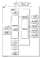
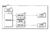
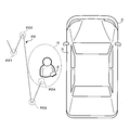
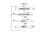
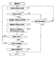
- FIG. 1 is a schematic diagram illustrating a configuration example of a vehicle communication system according to a first embodiment. It is a block diagram which shows the example of 1 structure of vehicle equipment. It is a block diagram which shows one structural example of a portable device. It is a conceptual diagram which shows an example of a predetermined position range and a position change. It is a conceptual diagram which shows the other example of a predetermined position range and a position change. It is a flowchart which shows the process sequence which concerns on the detection of the portable device for door opening operation. It is a flowchart which shows the process sequence which concerns on an opening process. It is a flowchart which shows the process sequence which concerns on the detection of the portable device for opening / closing operation. It is a flowchart which shows the process sequence which concerns on a door closing process.
- a vehicle communication system includes an in-vehicle device having an in-vehicle transmission unit that transmits a position detection signal, the position detection signal, and the received position detection signal.
- a vehicle-mounted device that transmits a response signal, and the vehicle-mounted device is based on the response signal received from the portable device, and instructs to automatically open or close the vehicle door.
- a vehicle communication system that outputs a door closing instruction signal, wherein the in-vehicle device identifies a position of the portable device relative to the vehicle and a change in the position based on the received response signal; and the vehicle
- the storage unit that stores the predetermined position range and position change of the portable device with respect to the position, the position specified by the specifying unit and the change in the position, and the predetermined position range and position change stored in the storage unit are compared. That includes a comparison unit, in accordance with the comparison result by the comparing unit, and said door-opening instruction signal or the output unit to output the closing command signal.
- the vehicle-mounted device transmits a position detection signal for detecting the position of the portable device.
- the portable device that has received the position detection signal transmitted from the in-vehicle device transmits a response signal corresponding to the position detection signal to the in-vehicle device.
- the response signal is for specifying the position of the portable device relative to the vehicle-mounted device and the change in the position.
- the specifying unit of the in-vehicle device receives the response signal, and specifies the position of the portable device and a change in the position based on the received response signal. Since the position detection signal is transmitted and the portable device is configured to transmit a response signal corresponding to the position detection signal, the specifying unit can specify the position of the portable device and the change in the position.
- the change in the position of the portable device corresponds to the opening or closing operation of the vehicle door by the user.
- the storage unit stores a predetermined position range and position change of the portable device with respect to the vehicle as an operation condition for opening or closing the vehicle door.
- the comparison unit compares the position of the portable device identified by the identification unit based on the response signal and the change in the position with the predetermined position range and position change stored in the storage unit, and the output unit compares the position Depending on the comparison result, the door opening instruction signal for instructing automatic opening of the vehicle door or the door closing instruction signal for instructing automatic closing is output.
- the user holding the portable device moves along a predetermined route and reaches a predetermined position range.
- the vehicle door can be automatically opened or closed.
- the change in the position specified by the specifying unit is similar to the predetermined position change stored in the storage unit, and the position specified by the specifying unit is the predetermined value.
- the position specified by the specifying unit is the predetermined value.
- the output unit when the position change of the portable device is similar to the predetermined position change and the position of the portable device specified by the specifying unit is included in the predetermined position range, the output unit is A door opening instruction signal is output and the vehicle door is automatically opened. Similarly, when the position change of the portable device is similar to the predetermined position change and the position of the portable device specified by the specifying unit is included in the predetermined position range, the output unit instructs to close the door. It can also be configured to output a signal and automatically close the vehicle door.
- the output unit A configuration that outputs a door instruction signal or the door closing instruction signal is preferable.
- the output unit when the position of the portable device is included in the predetermined position range within a predetermined time after performing a change similar to the predetermined position change, the output unit outputs the door opening instruction signal or A door closing instruction signal can be output to automatically open or close the vehicle door. That is, a user having a portable device moves along a predetermined route and then moves to a predetermined position range within a predetermined time, whereby a vehicle door such as an electric slide door can be automatically opened or closed. .
- the predetermined position change includes information on a positional relationship between a plurality of points at which the movement mode of the portable device changes.
- the predetermined position change stored in the storage unit is configured to include positional relationship information of a plurality of points at which the movement mode of the portable device changes.
- a route in which the movement mode of the portable device changes at a plurality of locations is a route that is unlikely to move the portable device against the user's will. Accordingly, it is possible to effectively prevent the vehicle door from automatically opening or closing against the user's will.
- the predetermined position change includes a position change along an annular path of the portable device.
- the predetermined position change stored in the storage unit includes a position change along an annular path.
- the annular route is a route that is unlikely to move the portable device against the user's will. Accordingly, it is possible to effectively prevent the vehicle door from automatically opening or closing against the user's will.
- the predetermined position change includes a position change along a path bent in the middle of the portable device.
- the predetermined position change stored in the storage unit includes a position change along a path bent in the middle.
- the route that is bent along the way is a route that is unlikely to move the portable device against the intention of the user. Accordingly, it is possible to effectively prevent the vehicle door from automatically opening or closing against the user's will.
- the in-vehicle device is configured to transmit the position detection signal from a plurality of antennas provided in the vehicle, and the portable device measures the received signal strength of each received position detection signal.
- the structure provided with the position detection part which detects the position of the said portable apparatus with respect to the said vehicle equipment is preferable.
- the vehicle-mounted device transmits the position detection signal from the plurality of antennas provided in the vehicle.
- the portable device measures the received signal strength of the position detection signal transmitted from each antenna by the measuring unit, and the portable device transmitting unit transmits a response signal including the measured received signal strength to the in-vehicle device.
- the received signal strength of the position detection signals transmitted from the plurality of antennas in the portable device is for two-dimensionally or three-dimensionally detecting the position of the portable device with respect to the in-vehicle device.
- the specifying unit detects the position of the portable device relative to the in-vehicle device based on the received signal strength included in the response signal, and specifies the change in the position of the portable device two-dimensionally or three-dimensionally. Therefore, the opening or closing of the vehicle door can be operated by moving the portable device two-dimensionally or three-dimensionally along a predetermined route.
- the vehicle-mounted device transmits the position detection signal from a plurality of antennas provided in the vehicle, and the portable device measures the received signal strength of each received position detection signal. Based on the received signal strength measured by the measurement unit, the measurement unit, a position detection unit that detects the position of the portable device with respect to the in-vehicle device, and the response signal that includes the position detected by the position detection unit It is preferable to include a portable transmission unit that transmits to the in-vehicle device, and the specifying unit specifies a position included in the response signal.
- the vehicle-mounted device transmits the position detection signal from the plurality of antennas provided in the vehicle.
- the portable device measures the received signal strength of the position detection signal transmitted from each antenna by the measuring unit, and the position detecting unit detects the position of the portable device with respect to the in-vehicle device based on the measured received signal strength.
- the received signal strength of the position detection signals transmitted from the plurality of antennas in the portable device is for two-dimensionally or three-dimensionally detecting the position of the portable device with respect to the in-vehicle device. Then, the portable device transmits a response signal including the detected position to the in-vehicle device.
- the specifying unit specifies the position of the portable device and a change in the position two-dimensionally or three-dimensionally based on the response signal. Therefore, the opening or closing of the vehicle door can be operated by moving the portable device two-dimensionally or three-dimensionally along a predetermined route.
- the vehicle-mounted device When the vehicle-mounted device according to one aspect of the present invention transmits a position detection signal and receives a response signal transmitted from the portable device in accordance with the position detection signal, the vehicle-mounted device is based on the received response signal.
- An in-vehicle device that outputs a door opening instruction signal for instructing to automatically open the vehicle door or a door closing instruction signal for instructing to automatically close the vehicle door, the portable device for the vehicle based on the received response signal
- a specifying unit for specifying the position and a change in the position
- a storage unit for storing a predetermined position range and a position change of the portable device with respect to the vehicle, a position specified by the specifying unit and a change in the position
- a comparison unit that compares the predetermined position range and position change stored in the storage unit, and an output unit that outputs the door opening instruction signal or the door closing instruction signal according to a comparison result by the comparison unit.
- the vehicle door can be automatically opened or closed.
- a computer program automatically opens a vehicle door to a computer based on a response signal transmitted from the portable device in response to a position detection signal transmitted to the portable device.
- a specifying unit that identifies a change, a comparison unit that compares the position specified by the specifying unit and a change in the position, a predetermined position range and a change in position, and the opening according to a comparison result by the comparison unit. It functions as an output unit that outputs an instruction signal or the door closing instruction signal.
- the computer can function as the vehicle-mounted device described in aspect (9).
- FIG. 1 is a schematic diagram illustrating a configuration example of a vehicle communication system according to the first embodiment.
- the vehicle communication system according to the first embodiment is configured between an in-vehicle device 1 that transmits and receives various signals using a plurality of LF transmitting antennas 3 and RF receiving antennas 4 provided in the vehicle C, and the in-vehicle device 1.
- a portable device 2 that transmits and receives the signal.
- the in-vehicle device 1 identifies the position of the portable device 2 and the change in the position, and automatically opens the automatic sliding door D when the position of the portable device 2 and the position change coincide with a predetermined position range and position change. .
- the plurality of LF transmission antennas 3 include, for example, a first LF transmission antenna 31 disposed on the driver side pillar, a second LF transmission antenna 32 disposed on the passenger side pillar, and a third LF disposed on the rear portion of the vehicle C.
- the transmission antenna 33 and the fourth LF transmission antenna 34 disposed at the front portion.
- Each LF transmitting antenna 3 transmits a signal using LF band radio waves.
- FIG. 2 is a block diagram showing a configuration example of the in-vehicle device 1.
- the in-vehicle device 1 is a computer having, for example, one or a plurality of CPUs (Central Processing Unit), a multi-core CPU, a ROM (Read Only Memory), a RAM (Random Access Memory), an input / output interface, a timing unit 11a, and the like.
- the CPU of the in-vehicle controller 11 is connected to the in-vehicle receiver 12, the in-vehicle transmitter 13, the storage unit 14, and the output unit 15 through an input / output interface.
- the in-vehicle control unit 11 controls the operation of each component by executing a computer program 80 (described later) stored in the storage unit 14, identifies the position change of the portable device 2, and automatically sets the automatic sliding door D. Instruct to open.
- the storage unit 14 is a nonvolatile memory such as an EEPROM (ElectricallyrErasable Programmable ROM) or a flash memory.
- the storage unit 14 is a computer for the vehicle-mounted control unit 11 to control the operation of each component of the vehicle-mounted device 1 to identify a change in the position of the portable device 2 and to instruct to automatically open the automatic sliding door D.
- a program 80 is stored.
- the storage unit 14 stores a predetermined position range and position change of the portable device 2 with respect to the in-vehicle device 1.
- the predetermined position range and position change correspond to operating conditions for automatically opening the automatic sliding door D.
- an example in which the storage unit 14 stores the predetermined position range and position change in advance will be described.
- the user may store any predetermined position range and position change in the storage unit 14. It may be configured. Details of the predetermined position range and position change will be described later.
- the in-vehicle control unit 11 and the storage unit 14 are illustrated as separate components, but the storage unit 14 may be provided inside the in-vehicle control unit 11.
- the computer program 80 according to the first embodiment may be recorded in the recording medium 8 so as to be readable by a computer.
- the storage unit 14 stores a computer program 80 read from the recording medium 8 by a reading device (not shown).
- the recording medium 8 is an optical disc such as CD (Compact Disc) -ROM, DVD (Digital Versatile Disc) -ROM, BD (Blu-ray (registered trademark) Disc), a flexible disc, a magnetic disc such as a hard disc, a magnetic optical disc, and a semiconductor memory.
- the computer program 80 according to the first embodiment may be downloaded from an external computer (not shown) connected to a communication network (not shown) and stored in the storage unit 14.
- the in-vehicle receiving unit 12 is connected to the RF receiving antenna 4 and receives various response signals transmitted from the portable device 2 using radio waves in the UHF band and outputs them to the in-vehicle control unit 11. Since the communicable region is wide in the UHF band, the arrangement of the RF receiving antenna 4 in the vehicle C is not particularly limited.
- the in-vehicle transmission unit 13 is connected to the plurality of LF transmission antennas 3 and transmits a signal for specifying the position change of the portable device 2 according to the control of the in-vehicle control unit 11.
- the in-vehicle transmission unit 13 transmits a process start signal for starting a process related to opening of the automatic sliding door D according to the control of the in-vehicle control unit 11.
- the in-vehicle transmission unit 13 transmits a position detection signal for detecting the position of the portable device 2 according to the control of the in-vehicle control unit 11.
- the strength of the signal transmitted from each LF transmission antenna 3 is set so that the portable device 2 can receive signals from two or more LF transmission antennas 3.
- a door ECU 6 is connected to the output unit 15, and the output unit 15 automatically opens the door opening instruction signal or the automatic sliding door D instructing to automatically open the automatic sliding door D according to the control of the in-vehicle control unit 11.
- a door closing instruction signal for instructing closing is output to the door ECU 6.
- the door ECU 6 drives the sliding door driving unit 61 according to the door opening instruction signal output from the output unit 15 of the in-vehicle device 1 to open the automatic sliding door D.
- the door ECU 6 drives the sliding door driving unit 61 according to the door closing instruction signal output from the output unit 15 of the in-vehicle device 1 to close the automatic sliding door D.
- the automatic sliding door D includes a sliding door portion and a sliding mechanism that moves the sliding door portion in the opening direction or the closing direction, and the sliding door driving portion 61 is a power of a motor or the like that drives the sliding mechanism. Provide a source.
- the slide door drive unit 61 drives the slide mechanism by the motor to move the slide door unit in the door opening direction or the door closing direction.
- a sliding door switch 5 is connected to the in-vehicle control unit 11, and a door signal corresponding to the operation state of the sliding door switch 5 is input to the in-vehicle control unit 11.
- the in-vehicle controller 11 can recognize the operation state of the slide door switch 5 based on the door signal of the slide door switch 5.
- the in-vehicle control unit 11 outputs a door opening instruction signal or a door closing instruction signal to the door ECU 6 at the output unit 15 to open or close the automatic sliding door D.
- the on-vehicle controller 11 is connected to an open / close detection switch 7 for detecting the open / closed state of the automatic sliding door D.
- the opening / closing detection switch 7 inputs an opening / closing signal that is turned on / off in response to opening / closing of the automatic sliding door D to the in-vehicle controller 11.
- the in-vehicle controller 11 can recognize the open / closed state of the automatic sliding door D based on the input open / close signal.
- FIG. 3 is a block diagram illustrating a configuration example of the portable device 2.
- the portable device 2 includes a portable control unit 21 that controls the operation of each component of the portable device 2.
- the portable control unit 21 is a microcomputer having, for example, one or a plurality of CPUs, a multi-core CPU, and the like.
- the portable control unit 21 is provided with a portable reception unit 22, a portable transmission unit 23, a storage unit 24, and a received signal strength measurement unit 25.
- the portable control unit 21 reads out a control program, which will be described later, stored in the storage unit 24 and controls the operation of each component, thereby providing information necessary for specifying the position change of the portable device 2 with respect to the vehicle-mounted device 1. The process of transmitting to the machine 1 is executed.
- the storage unit 24 is a non-volatile memory similar to the storage unit 14.
- the storage unit 24 performs a process of transmitting a response signal including information for specifying the position change of the portable device 2 to the in-vehicle device 1 by the portable control unit 21 controlling the operation of each component of the portable device 2.
- a control program for execution is stored.
- the portable receiving unit 22 is connected to the LF receiving antenna 22a, receives various signals such as a processing start signal and a position detection signal transmitted from the vehicle-mounted device 1 using radio waves in the LF band, and sends them to the portable control unit 21. Output.
- the LF receiving antenna 22a is, for example, a triaxial antenna, and a constant received signal strength can be obtained regardless of the orientation or posture of the portable device 2 with respect to the vehicle C.
- the reception signal strength measurement unit 25 detects the reception signal strength of each position detection signal transmitted from the plurality of LF transmission antennas 3 and received by the LF reception antenna 22 a, and outputs the detected reception signal strength to the portable control unit 21. Circuit.
- the portable transmission unit 23 is connected to the RF transmission antenna 23 a and transmits a signal corresponding to the signal transmitted from the portable device 2 according to the control of the portable control unit 21. Specifically, when the portable device 2 receives a process start signal for starting the process related to the opening of the automatic sliding door D, the portable transmitter 23 sends a predetermined reply signal according to the control of the portable controller 21. Send. Further, when the portable device 2 receives the position detection signal, the portable transmission unit 23 receives the information as the information for specifying the position of the portable device 2 with respect to the vehicle-mounted device 1 and the change in the position according to the control of the portable control unit 21. A response signal including the received signal strength measured by the signal strength measuring unit 25 is transmitted. The portable transmitter 23 transmits a response signal using UHF radio waves.
- the UHF band is an example of a radio wave band for transmitting signals, and is not necessarily limited to this.
- FIG. 4 is a conceptual diagram showing an example of a predetermined position range and position change.
- the predetermined position range stored in the storage unit 14 is a position range R in the vicinity of the automatic sliding door D, for example, a range of a predetermined distance from the automatic sliding door D.
- the predetermined position change stored in the storage unit 14 is, for example, a position change P1 along an annular path, and information on the positional relationship between a plurality of points P11, P12, P3, and P14 at which the movement mode of the portable device 2 changes. including. Points P11 and P14 at which the movement mode changes are points where the portable device has started moving, points where the movement has ended, and points P12 and P13 are points at which the moving direction has changed.
- the position change P1 is, for example, a substantially triangular or substantially trapezoidal path in the horizontal plane.
- the triangular path is an example, and may be an annular, quadrangular, other polygonal path, or a curved closed path.
- the route need not be a two-dimensional route on a horizontal plane, and may be a route on a vertical plane, a route on a plane intersecting the horizontal plane, or a non-planar three-dimensional path. It may be a closed path.
- the annular path does not need to be a completely closed ring, and the annular path includes a substantially C-shaped path having an open start point and an end point.
- FIG. 5 is a conceptual diagram showing another example of the predetermined position range and position change.
- the predetermined position change stored in the storage unit 14 is, for example, a position change P2 along a path bent in the middle, and the positional relationship between a plurality of points P21, P22, P23, and P24 at which the movement mode of the portable device 2 changes. Contains information. More specifically, the position change P2 is, for example, a path having a first straight path in the horizontal plane, a second straight path bent from the straight path, and a third bent straight path. Note that the path of the position change P2 illustrated in FIG. 5 is an example, and may be a path that is bent at two or four or more points, or may be a curved path. Similarly to the position change P1, the position change P2 does not need to be a two-dimensional path on the horizontal plane, and may be a path on the vertical plane or a path on a plane intersecting the horizontal plane. A non-planar path may be used.
- FIG. 6 is a flowchart showing a processing procedure related to detection of the portable device 2 for the door opening operation.
- the in-vehicle control unit 11 causes the in-vehicle transmission unit 13 to transmit a processing start signal for starting processing related to opening of the automatic sliding door D from the LF transmission antenna 3 (step S1).
- the processing start signal is transmitted at a predetermined cycle.
- the portable device 2 is periodically activated to receive a signal transmitted from the in-vehicle device 1.
- the portable device 2 receives and receives the process start signal.
- a predetermined reply signal corresponding to the processed start signal is transmitted to the in-vehicle device 1 by the UHF band radio wave.
- the in-vehicle control unit 11 determines whether or not the in-vehicle receiving unit 12 has received a predetermined reply signal transmitted from the portable device 2 (step S2). When it determines with not receiving the predetermined reply signal (step S2: NO), the vehicle-mounted control part 11 returns a process to step S1.
- step S3 determines whether or not the automatic sliding door D is in a closed state based on the opening / closing signal from the opening / closing detection switch 7. (Step S3). When it determines with the automatic sliding door D being in an open state (step S3: NO), the vehicle-mounted control part 11 returns a process to step S1. When it determines with the automatic sliding door D being in a closed state (step S3: YES), the vehicle-mounted control part 11 performs the door opening process of the automatic sliding door D (step S4).
- the in-vehicle control unit 11 When the opening operation of the automatic sliding door D is detected due to a change in the position of the portable device 2, the in-vehicle control unit 11 sends an opening instruction signal for instructing to automatically open the automatic sliding door D via the output unit 15. The process which outputs to door ECU6 is performed. The vehicle-mounted control part 11 which finished the door opening process of the automatic sliding door D returns a process to step S1.
- FIG. 7 is a flowchart showing a processing procedure related to the door opening process.
- the in-vehicle control unit 11 causes the in-vehicle transmission unit 13 to sequentially transmit the position detection signal from the first to fourth LF transmission antennas 31, 32, 33, and 34 (step S11).
- the strengths of the position detection signals transmitted from the first to fourth LF transmission antennas 31, 32, 33, and 34 are substantially the same.
- the in-vehicle transmission unit 13 transmits a position detection signal from the first LF transmission antenna 31 and then transmits a position detection signal having the same strength as the position detection signal from the second LF transmission antenna 32.
- the in-vehicle transmission unit 13 transmits a position detection signal from the third LF transmission antenna 33, and then transmits a position detection signal from the fourth LF transmission antenna 34.
- the portable device 2 measures the reception signal strength of the position detection signals transmitted from the first to fourth LF transmission antennas 31, 32, 33, and 34 by the reception signal strength measurement unit 25, and obtains the reception obtained by the measurement.
- a response signal including the signal strength is transmitted to the vehicle-mounted device 1 by the portable transmission unit 23.
- the in-vehicle control unit 11 determines whether or not the in-vehicle receiving unit 12 has received a response signal from the portable device 2 with respect to the position detection signal within a predetermined period (step S12). When it is determined that the response signal has not been received (step S12: NO), the in-vehicle controller 11 determines whether or not the reception of the response signal for the transmission of the position detection signal has failed a predetermined number of times (step S13). . When it determines with having failed a predetermined number of times (step S13: YES), the vehicle-mounted control part 11 finishes a process.
- step S13 NO
- the in-vehicle control unit 11 finishes the door opening process. If it is determined that the number of reception failures is less than the predetermined number (step S13: NO), the in-vehicle control unit 11 returns the process to step S11.
- the vehicle-mounted control part 11 detects the position of the portable device 2 with respect to the vehicle C based on the received signal strength included in the response signal, and the detected position and position.
- the points in time when detection is performed are stored in association with each other (step S14).
- the time point when the position detection is performed can be measured by the timer unit 11a. Since the reception signal strength of the signal transmitted from each LF transmission antenna 3 corresponds to the distance between the portable device 2 and the corresponding LF transmission antenna 3, the received signal strength is used to transmit the portable device 2 and each LF transmission.
- the positional relationship with the antenna 3 can be specified, that is, the position of the portable device 2 can be detected.
- the in-vehicle control unit 11 stores a history of position changes of the portable device 2 by the process of step S14.
- the distance between the first LF transmission antenna 31 and the portable device 2 can be estimated by the received signal strength of the position detection signal transmitted from the first LF transmission antenna 31.
- the positional relationship between the second to fourth LF transmission antennas 34 and the portable device 2 is determined according to the received signal strength of each position detection signal transmitted from each of the second to fourth LF transmission antennas 32, 33, 34. Can be estimated.
- the received signal strength of the position detection signals from the four first to fourth LF transmitting antennas 31, 32, 33, and 34 is used to three-dimensionally position the portable device 2 with respect to the vehicle C. Can be detected.
- the in-vehicle control unit 11 identifies a change in the position of the portable device 2 based on the stored position history of the portable device 2 (step S15). Since the position of the portable device 2 is detected by a position detection signal transmitted at a high cycle of several hundred milliseconds, the position or position change of the portable device 2 can be specified in detail. It should be noted that the position change of the portable device 2 in step S15 may be specified after the history of the position of the portable device 2 is accumulated to some extent.
- the in-vehicle control unit 11 compares the position change specified in step S15 with the predetermined position change stored in the storage unit 14 (step S16), and determines whether the position change is similar. (Step S17). It should be noted that the position change of all paths after the portable device 2 starts position detection and the predetermined position change do not have to be similar, and the predetermined position change occurs during the position change of the portable device 2. It is sufficient if a position change similar to is included. When it determines with a position change not being similar (step S17: NO), the vehicle-mounted control part 11 returns a process to step S11.
- step S17 When it is determined that the position changes are similar (step S17: YES), the in-vehicle control unit 11 determines the position of the portable device 2 specified within a predetermined time after the position change similar to the predetermined position change. Then, it is determined whether or not it is included in a predetermined position range (step S18). When it determines with the position of the portable device 2 not being contained in the predetermined position range (step S18: NO), the vehicle-mounted control part 11 returns a process to step S11. When it is determined that the position of the portable device 2 is included in the predetermined position range (step S18: YES), the in-vehicle control unit 11 outputs a door opening instruction signal instructing to automatically open the automatic sliding door D. It outputs to door ECU6 in the part 15 (step S19), and a process is complete
- the door opening process is performed under a predetermined condition. You may comprise so that it may once complete
- the position change of the portable device 2 possessed by the user is similar to the predetermined position change stored in the storage unit 14, and the subsequent position of the portable device 2 is the storage unit. If it is included in the predetermined range stored in 14, the automatic sliding door D is automatically opened. Therefore, even if the device does not include a new device such as a voice sensor, the user who has the portable device 2 moves along a predetermined route and reaches a predetermined position range, so that the automatic sliding door D is automatically set. Can be opened.
- the in-vehicle device 1 changes when the position of the portable device 2 possessed by the user changes in a path similar to the predetermined position change, and then the position of the portable device 2 is included in the predetermined range within a predetermined time,
- the automatic sliding door D is automatically opened. Therefore, as shown in FIG. 5, when the user approaches the vehicle C while moving along a route similar to a predetermined position change and moves to a predetermined position range, the door opening operation has already been completed.
- the automatic sliding door D can be opened. That is, the user does not need to move to the vicinity of the automatic sliding door D and move the portable device 2 along the predetermined route at that location, and can open the automatic sliding door D more efficiently.
- the portable device 2 since the position detection signal transmitted from the plurality of LF transmitting antennas 3 is used to identify the position change of the portable device 2, the portable device 2 is moved two-dimensionally or three-dimensionally along a predetermined route. By doing so, the automatic sliding door D can be automatically opened.
- the position change stored in the storage unit 14 is information including information on the positional relationship between a plurality of points at which the movement mode of the portable device 2 changes.
- the position change P1 is an annular path
- the position change P2 is in the middle. It is a bent path.
- Modification 1 In the first embodiment, the process of detecting the position of the portable device 2 on the in-vehicle device 1 side based on the received signal strength has been described. However, the portable device 2 detects its own position with respect to the in-vehicle device 1 and detects it. The response signal including the positional information obtained in this way may be configured to be transmitted to the in-vehicle device 1 by the portable transmission unit 23. The in-vehicle device 1 stores position information included in the response signal transmitted from the portable device 2, and specifies the position of the portable device 2 and a change in the position based on the stored position information.
- the automatic sliding door D can be opened automatically.
- the vehicle communication system according to the second embodiment has a function of closing the automatic sliding door D by moving the portable device 2 along a predetermined route in addition to the same functions as those of the first embodiment.
- the vehicle-mounted control unit 11 controls the operation of each component of the vehicle-mounted device 1 to identify the position change of the portable device 2 and automatically open the automatic sliding door D.
- a computer program for instructing and instructing automatic closing is stored.
- the storage unit 14 stores a predetermined position change and position range for closing corresponding to an operation condition for automatically closing the automatic sliding door D in addition to the predetermined position change and position range for opening the door. .
- the vehicular communication system according to the second embodiment differs from the first embodiment in the processing procedure of the in-vehicle control unit 11, the following mainly describes the differences. Since other configurations and operational effects are the same as those of the first embodiment, the corresponding portions are denoted by the same reference numerals, and detailed description thereof is omitted.
- FIG. 8 is a flowchart showing a processing procedure related to detection of the portable device 2 for opening / closing operation.
- the in-vehicle control unit 11 causes the in-vehicle transmission unit 13 to transmit a processing start signal for starting processing related to opening of the automatic sliding door D from the LF transmission antenna 3 (step S201).
- the in-vehicle controller 11 determines whether or not the in-vehicle receiver 12 has received a predetermined reply signal transmitted from the portable device 2 (step S202). When it determines with not receiving the predetermined reply signal (step S202: NO), the vehicle-mounted control part 11 returns a process to step S201.
- step S203 determines whether or not the automatic sliding door D is in the closed state based on the opening / closing signal from the opening / closing detection switch 7.
- step S203 determines with the automatic sliding door D being in a closed state
- step S204 the vehicle-mounted control part 11 performs the door opening process of the automatic sliding door D (step S204).
- the contents of the door opening process are the same as in the first embodiment.
- step S205 the automatic sliding door D is closed (step S205).
- the in-vehicle control unit 11 outputs a door closing instruction signal for instructing to automatically close the automatic sliding door D via the output unit 15 when the closing operation of the automatic sliding door D is detected due to the position change of the portable device 2. Execute the process to output to.
- step S204 The vehicle-mounted control part 11 which finished the process of step S204 or step S205 returns a process to step S201.
- FIG. 9 is a flowchart showing a processing procedure related to the door closing process.
- the in-vehicle control unit 11 executes the same processing as Steps S11 to S15 of the first embodiment, Steps S211 to S215. That is, the in-vehicle control unit 11 transmits a position detection signal by the in-vehicle transmission unit 13, detects the position of the portable device 2 relative to the in-vehicle device 1 based on the response signal from the portable device 2, and determines the position of the portable device 2. A process for identifying the change is executed.
- the vehicle-mounted control unit 11 compares the position change specified in step S215 with the predetermined position change for closing that is stored in the storage unit 14 (step S216), and whether or not the position change is similar. Is determined (step S217). When it determines with the position change not being similar (step S217: NO), the vehicle-mounted control part 11 returns a process to step S211. If it is determined that the position change is similar (step S217: YES), the in-vehicle controller 11 determines that the position of the portable device 2 specified within a predetermined time after the position change similar to the predetermined position change. Then, it is determined whether or not it is included in the predetermined position range (step S218).
- step S218: NO the vehicle-mounted control part 11 returns a process to step S211.
- step S218: YES the door ECU 6 outputs a door closing instruction signal for instructing the automatic sliding door D to be automatically closed via the output unit 15.
- the user who has the portable device 2 moves along a predetermined route and automatically reaches the predetermined position range.
- the sliding door D can be automatically opened and closed.
- Other functions and effects are the same as those of the first embodiment.
- Modification 2 In the second embodiment, the process of detecting the position of the portable device 2 on the in-vehicle device 1 side based on the received signal strength has been described. However, the portable device 2 detects its own position with respect to the in-vehicle device 1 and detects it. The response signal including the positional information obtained in this way may be configured to be transmitted to the in-vehicle device 1 by the portable transmission unit 23. The in-vehicle device 1 stores the position information included in the response signal transmitted from the portable device 2, and specifies the position change of the portable device 2 based on the stored position information.
- the automatic sliding door D can be automatically opened and closed.
Landscapes
- Engineering & Computer Science (AREA)
- Physics & Mathematics (AREA)
- General Physics & Mathematics (AREA)
- Radar, Positioning & Navigation (AREA)
- Remote Sensing (AREA)
- Mechanical Engineering (AREA)
- Power-Operated Mechanisms For Wings (AREA)
- Lock And Its Accessories (AREA)
- Position Fixing By Use Of Radio Waves (AREA)
Abstract
携帯機を所持する使用者が所定経路を移動し、所定の位置範囲に到達することによって、車両ドアを自動で開扉又は閉扉させることができる車両用通信システムを提供する。 車両用通信システムは、位置検出用信号を送信する車載機1と、前記位置検出用信号を受信し、該位置検出用信号に応じた応答信号を送信する携帯機2とを備える。車載機1は、受信した前記応答信号に基づいて、車両Cに対する携帯機2の位置及び該位置の変化を特定する特定部と、車両Cに対する携帯機2の所定の位置範囲及び位置変化を記憶する記憶部と、前記特定部が特定した位置及び該位置の変化並びに前記記憶部が記憶する前記所定の位置範囲及び位置変化を比較する比較部と、該比較部による比較結果に応じて、車両ドアを自動で開けることを指示する開扉指示信号又は自動で閉めることを指示する閉扉指示信号を出力する出力部とを備える。
Description
本発明は、車両ドアを自動で開けることを指示する開扉指示信号又は車両ドアを自動で閉めることを指示する閉扉指示信号を出力する車両用通信システム及び車載機、並びにコンピュータを該車載機として機能させるためのコンピュータプログラムに関する。
電動スライドドアを備えた車両が実用化されている。特許文献1には、正規の電子キーを所持する使用者によって車両のドアハンドルが引かれたことを検知した場合、電動スライドドアを自動的に開扉する車両スライドドア制御装置が開示されている。また、ドアハンドルに設けられたタッチセンサによって、使用者がドアハンドルに触れたことを検知した場合、電動スライドドアを自動的に開扉する技術が開示されている。
特許文献2には、車両に近づいた使用者が所持する電子キーを認証し、正規の電子キーを所持する使用者が発する特定の言葉を検出した場合、電動スライドドアを自動的に開扉する車両スライドドア制御装置が開示されている。
しかしながら、特許文献1の車両ドア制御システムにおいては、携帯機を所持している使用者がドアハンドル又はタッチセンサを操作する必要があり、荷物等で両手がふさがっているような場合、電動スライドドアの操作が不便であるという問題があった。
特許文献2の車両用施解錠システムにおいては、使用者の両手がふさがっていても、電動スライドドアを自動開扉させることができるが、車両外部に音声センサを新たに設ける必要があり、高コストになるという問題があった。また、使用者が不本意で前記特定の言葉を発した場合、あるいは周囲の音を前記特定の言葉と誤認識した場合、電動スライドドアが誤って自動開扉してしまうという問題があった。
本願の目的は、音声センサ等の新たな機器を備えない構成であっても、携帯機を所持する使用者が所定経路を移動し、所定の位置範囲に到達することによって、電動スライドドア等の車両ドアを自動で開扉又は閉扉させることができる車両用通信システム及び車載機、並びにコンピュータを該車載機として機能させるためのコンピュータプログラムを提供することにある。
本発明の一態様に係る車両用通信システムは、位置検出用信号を送信する車載送信部を有する車載機と、前記位置検出用信号を受信し、受信した前記位置検出用信号に応じた応答信号を送信する携帯機とを備え、前記車載機は該携帯機から受信した前記応答信号に基づいて、車両ドアを自動で開けることを指示する開扉指示信号又は自動で閉めることを指示する閉扉指示信号を出力する車両用通信システムであって、前記車載機は、受信した前記応答信号に基づいて、車両に対する前記携帯機の位置及び該位置の変化を特定する特定部と、前記車両に対する前記携帯機の所定の位置範囲及び位置変化を記憶する記憶部と、前記特定部が特定した位置及び該位置の変化と、前記記憶部が記憶する前記所定の位置範囲及び位置変化とを比較する比較部と、該比較部による比較結果に応じて、前記開扉指示信号又は前記閉扉指示信号を出力する出力部とを備える。
本発明の一態様に係る車載機は、位置検出用信号を送信し、該位置検出用信号に応じて携帯機から送信された応答信号を受信した場合、受信した前記応答信号に基づいて、車両ドアを自動で開けることを指示する開扉指示信号又は自動で閉めることを指示する閉扉指示信号を出力する車載機であって、受信した前記応答信号に基づいて、車両に対する前記携帯機の位置及び該位置の変化を特定する特定部と、前記車両に対する前記携帯機の所定の位置範囲及び位置変化を記憶する記憶部と、前記特定部が特定した位置及び該位置の変化と、前記記憶部が記憶する前記所定の位置範囲及び位置変化とを比較する比較部と、該比較部による比較結果に応じて、前記開扉指示信号又は前記閉扉指示信号を出力する出力部とを備える。
本発明の一態様に係るコンピュータプログラムは、コンピュータに、携帯機へ送信された位置検出用信号に応じて該携帯機から送信された応答信号に基づいて、車両ドアを自動で開けることを指示する開扉指示信号又は自動で閉めることを指示する閉扉指示信号を出力させるコンピュータプログラムであって、コンピュータを、受信した前記応答信号に基づいて、車両に対する前記携帯機の位置及び該位置の変化を特定する特定部と、前記特定部が特定した位置及び該位置の変化と、所定の位置範囲及び位置変化とを比較する比較部と、該比較部による比較結果に応じて、前記開扉指示信号又は前記閉扉指示信号を出力する出力部として機能させる。
なお、本願は、このような特徴的な処理部を備える車両用通信システム、車載機及び携帯機として実現することができるだけでなく、かかる特徴的な処理をステップとする車両通信方法として実現したり、かかるステップをコンピュータに実行させるためのプログラムとして実現したりすることができる。また、車両用通信システム、車載機及び携帯機の一部又は全部を実現する半導体集積回路として実現したり、車両用通信システム、車載機及び携帯機を含むその他のシステムとして実現したりすることができる。
上記によれば、音声センサ等の新たな機器を備えない構成であっても、携帯機を所持する使用者が所定経路を移動し、所定の位置範囲に到達することによって、電動スライドドア等の車両ドアを自動で開扉又は閉扉させることができる車両用通信システム及び車載機を提供することができる。
[本発明の実施形態の説明]
最初に本発明の実施態様を列記して説明する。また、以下に記載する実施形態の少なくとも一部を任意に組み合わせてもよい。
最初に本発明の実施態様を列記して説明する。また、以下に記載する実施形態の少なくとも一部を任意に組み合わせてもよい。
(1)本発明の一態様に係る車両用通信システムは、位置検出用信号を送信する車載送信部を有する車載機と、前記位置検出用信号を受信し、受信した前記位置検出用信号に応じた応答信号を送信する携帯機とを備え、前記車載機は該携帯機から受信した前記応答信号に基づいて、車両ドアを自動で開けることを指示する開扉指示信号又は自動で閉めることを指示する閉扉指示信号を出力する車両用通信システムであって、前記車載機は、受信した前記応答信号に基づいて、車両に対する前記携帯機の位置及び該位置の変化を特定する特定部と、前記車両に対する前記携帯機の所定の位置範囲及び位置変化を記憶する記憶部と、前記特定部が特定した位置及び該位置の変化と、前記記憶部が記憶する前記所定の位置範囲及び位置変化とを比較する比較部と、該比較部による比較結果に応じて、前記開扉指示信号又は前記閉扉指示信号を出力する出力部とを備える。
本態様によれば、車載機は携帯機の位置を検出するための位置検出用信号を送信する。車載機から送信された位置検出用信号を受信した携帯機は、該位置検出用信号に応じた応答信号を車載機へ送信する。応答信号は、車載機に対する携帯機の位置及び該位置の変化を特定するためのものである。
車載機の特定部は、応答信号を受信し、受信した応答信号に基づいて携帯機の位置と、該位置の変化を特定する。位置検出用信号が送信され、携帯機は該位置検出用信号に応じた応答信号を送信する構成であるため、特定部は携帯機の位置及び該位置の変化を特定することができる。携帯機の位置変化は使用者による車両ドアの開扉操作又は閉扉操作に対応するものである。記憶部は、車両ドアを開扉又は閉扉させる操作条件として、車両に対する携帯機の所定の位置範囲及び位置変化を記憶している。比較部は、応答信号に基づいて特定部が特定した携帯機の位置及び該位置の変化と、記憶部が記憶している前記所定の位置範囲及び位置変化とを比較し、出力部は比較部による比較結果に応じて、車両ドアを自動で開けることを指示する開扉指示信号又は自動で閉めることを指示する閉扉指示信号を出力する。
このように、本態様によれば、音声センサ等の新たな機器を備えない構成であっても、携帯機を所持する使用者が所定経路を移動し、所定の位置範囲に到達することによって、車両ドアを自動で開扉又は閉扉させることができる。
車載機の特定部は、応答信号を受信し、受信した応答信号に基づいて携帯機の位置と、該位置の変化を特定する。位置検出用信号が送信され、携帯機は該位置検出用信号に応じた応答信号を送信する構成であるため、特定部は携帯機の位置及び該位置の変化を特定することができる。携帯機の位置変化は使用者による車両ドアの開扉操作又は閉扉操作に対応するものである。記憶部は、車両ドアを開扉又は閉扉させる操作条件として、車両に対する携帯機の所定の位置範囲及び位置変化を記憶している。比較部は、応答信号に基づいて特定部が特定した携帯機の位置及び該位置の変化と、記憶部が記憶している前記所定の位置範囲及び位置変化とを比較し、出力部は比較部による比較結果に応じて、車両ドアを自動で開けることを指示する開扉指示信号又は自動で閉めることを指示する閉扉指示信号を出力する。
このように、本態様によれば、音声センサ等の新たな機器を備えない構成であっても、携帯機を所持する使用者が所定経路を移動し、所定の位置範囲に到達することによって、車両ドアを自動で開扉又は閉扉させることができる。
(2)前記出力部は、前記特定部が特定した位置の変化と、前記記憶部が記憶する前記所定の位置変化とが相似しており、かつ前記特定部が特定した位置が、前記所定の位置範囲に含まれている場合、前記開扉指示信号又は前記閉扉指示信号を出力する構成が好ましい。
本態様によれば、携帯機の位置変化と、前記所定の位置変化とが相似し、かつ特定部が特定した携帯機の位置が、前記所定の位置範囲に含まれている場合、出力部は開扉指示信号を出力し、車両ドアを自動で開ける。
同様にして、携帯機の位置変化と、前記所定の位置変化とが相似し、かつ特定部が特定した携帯機の位置が、前記所定の位置範囲に含まれている場合、出力部は閉扉指示信号を出力し、車両ドアを自動で閉めるように構成することもできる。
同様にして、携帯機の位置変化と、前記所定の位置変化とが相似し、かつ特定部が特定した携帯機の位置が、前記所定の位置範囲に含まれている場合、出力部は閉扉指示信号を出力し、車両ドアを自動で閉めるように構成することもできる。
(3)前記出力部は、前記所定の位置変化に相似する位置の変化の後、所定時間以内に特定された前記携帯機の位置が、前記所定の位置範囲に含まれている場合、前記開扉指示信号又は前記閉扉指示信号を出力する構成が好ましい。
本態様によれば、前記携帯機の位置が、前記所定の位置変化に相似する変化を行った後、所定時間以内に前記所定の位置範囲に含まれた場合、出力部は開扉指示信号又は閉扉指示信号を出力し、車両ドアを自動で開扉又は閉扉させることができる。つまり、携帯機を所持する使用者が所定経路を移動し、その後、所定時間以内に所定の位置範囲に移動することによって、電動スライドドア等の車両ドアを自動で開扉又は閉扉させることができる。
(4)前記所定の位置変化は、前記携帯機の移動態様が変化する複数の点の位置関係の情報を含む構成が好ましい。
本態様によれば、記憶部が記憶する前記所定の位置変化は、携帯機の移動態様が変化する複数の点の位置関係の情報を含む構成である。携帯機の移動態様が複数箇所で変化する経路は、使用者の意に反して携帯機が移動する可能性が低い経路である。従って、使用者の意に反して車両ドアが自動的に開き又は閉じることを効果的に防止することができる。
(5)前記所定の位置変化は前記携帯機の環状の経路に沿った位置変化を含む構成が好ましい。
本態様によれば、記憶部が記憶する前記所定の位置変化は環状の経路に沿った位置変化を含む構成である。環状の経路は、使用者の意に反して携帯機が移動する可能性が低い経路である。従って、使用者の意に反して車両ドアが自動的に開き又は閉じることを効果的に防止することができる。
(6)前記所定の位置変化は前記携帯機の途中で屈曲した経路に沿った位置変化を含む構成が好ましい。
本態様によれば、記憶部が記憶する前記所定の位置変化は途中で屈曲した経路に沿った位置変化を含む構成である。途中で屈曲した経路は、使用者の意に反して携帯機が移動する可能性が低い経路である。従って、使用者の意に反して車両ドアが自動的に開き又は閉じることを効果的に防止することができる。
(7)前記車載機は、前記車両に設けられた複数のアンテナから前記位置検出用信号を送信するようにしてあり、前記携帯機は、受信した各位置検出用信号の受信信号強度を測定する測定部と、該測定部が測定した前記受信信号強度を含む前記応答信号を前記車載機へ送信する携帯送信部とを備え、前記特定部は、前記応答信号に含まれる前記受信信号強度に基づいて、前記車載機に対する前記携帯機の位置を検出する位置検出部を備える構成が好ましい。
本態様によれば、車載機は車両に設けられた複数のアンテナから位置検出用信号を送信する。携帯機は各アンテナから送信された位置検出用信号の受信信号強度を測定部にて測定し、携帯機送信部は測定された受信信号強度を含む応答信号を車載機へ送信する。複数のアンテナから送信された位置検出用信号の携帯機における受信信号強度は、車載機に対する携帯機の位置を2次元的又は3次元的に検出するためのものである。特定部は、応答信号に含まれる受信信号強度に基づいて、車載機に対する携帯機の位置を位置検出部にて検出し、携帯機の位置変化を2次元的又は3次元的に特定する。
従って、所定経路で2次元的又は3次元的に携帯機を移動させることにより、車両ドアの開扉又は閉扉を操作することができる。
従って、所定経路で2次元的又は3次元的に携帯機を移動させることにより、車両ドアの開扉又は閉扉を操作することができる。
(8)前記車載機は、前記車両に設けられた複数のアンテナから前記位置検出用信号を送信するようにしてあり、前記携帯機は、受信した各位置検出用信号の受信信号強度を測定する測定部と、該測定部が測定した前記受信信号強度に基づいて、前記車載機に対する前記携帯機の位置を検出する位置検出部と、該位置検出部が検出した位置を含む前記応答信号を前記車載機へ送信する携帯送信部とを備え、前記特定部は、前記応答信号に含まれる位置を特定する構成が好ましい。
本態様によれば、車載機は車両に設けられた複数のアンテナから位置検出用信号を送信する。携帯機は各アンテナから送信された位置検出用信号の受信信号強度を測定部にて測定し、位置検出部は測定された受信信号強度に基づいて、車載機に対する携帯機の位置を検出する。複数のアンテナから送信された位置検出用信号の携帯機における受信信号強度は、車載機に対する携帯機の位置を2次元的又は3次元的に検出するためのものである。そして、携帯機は検出された位置を含む応答信号を車載機へ送信する。特定部は、応答信号に基づいて携帯機の位置及び該位置の変化を2次元的又は3次元的に特定する。
従って、所定経路で2次元的又は3次元的に携帯機を移動させることにより、車両ドアの開扉又は閉扉を操作することができる。
従って、所定経路で2次元的又は3次元的に携帯機を移動させることにより、車両ドアの開扉又は閉扉を操作することができる。
(9)本発明の一態様に係る車載機は、位置検出用信号を送信し、該位置検出用信号に応じて携帯機から送信された応答信号を受信した場合、受信した前記応答信号に基づいて、車両ドアを自動で開けることを指示する開扉指示信号又は自動で閉めることを指示する閉扉指示信号を出力する車載機であって、受信した前記応答信号に基づいて、車両に対する前記携帯機の位置及び該位置の変化を特定する特定部と、前記車両に対する前記携帯機の所定の位置範囲及び位置変化を記憶する記憶部と、前記特定部が特定した位置及び該位置の変化と、前記記憶部が記憶する前記所定の位置範囲及び位置変化とを比較する比較部と、該比較部による比較結果に応じて、前記開扉指示信号又は前記閉扉指示信号を出力する出力部とを備える。
本態様によれば、態様(1)と同様、音声センサ等の新たな機器を備えない構成であっても、携帯機を所持する使用者が所定経路を移動し、所定の位置範囲に到達することによって、車両ドアを自動で開扉又は閉扉させることができる。
(10)本発明の一態様に係るコンピュータプログラムは、コンピュータに、携帯機へ送信された位置検出用信号に応じて該携帯機から送信された応答信号に基づいて、車両ドアを自動で開けることを指示する開扉指示信号又は自動で閉めることを指示する閉扉指示信号を出力させるコンピュータプログラムであって、コンピュータを、受信した前記応答信号に基づいて、車両に対する前記携帯機の位置及び該位置の変化を特定する特定部と、前記特定部が特定した位置及び該位置の変化と、所定の位置範囲及び位置変化とを比較する比較部と、該比較部による比較結果に応じて、前記開扉指示信号又は前記閉扉指示信号を出力する出力部として機能させる。
本態様によれば、コンピュータを態様(9)に記載の車載機として機能させることがでる。
[本発明の実施形態の詳細]
本発明の実施形態に係る車両用通信システム、車載機及びコンピュータプログラムの具体例を、以下に図面を参照しつつ説明する。なお、本発明はこれらの例示に限定されるものではなく、請求の範囲によって示され、請求の範囲と均等の意味及び範囲内でのすべての変更が含まれることが意図される。
本発明の実施形態に係る車両用通信システム、車載機及びコンピュータプログラムの具体例を、以下に図面を参照しつつ説明する。なお、本発明はこれらの例示に限定されるものではなく、請求の範囲によって示され、請求の範囲と均等の意味及び範囲内でのすべての変更が含まれることが意図される。
(実施形態1)
図1は実施形態1に係る車両用通信システムの一構成例を示す模式図である。本実施形態1に係る車両用通信システムは、車両Cに設けられた複数のLF送信アンテナ3及びRF受信アンテナ4を用いて各種信号を送受信する車載機1と、該車載機1との間で該信号を送受信する携帯機2とを備える。車載機1は、携帯機2の位置及び該位置の変化を特定し、携帯機2の位置及び該位置変化が所定の位置範囲及び位置変化と一致した場合に、自動スライドドアDを自動で開く。
複数のLF送信アンテナ3は、例えば、運転席側のピラーに配された第1LF送信アンテナ31、助手席側のピラーに配された第2LF送信アンテナ32、車両Cの後部に配された第3LF送信アンテナ33及び前部に配された第4LF送信アンテナ34等である。各LF送信アンテナ3はLF帯の電波を用いて信号を送信する。
図1は実施形態1に係る車両用通信システムの一構成例を示す模式図である。本実施形態1に係る車両用通信システムは、車両Cに設けられた複数のLF送信アンテナ3及びRF受信アンテナ4を用いて各種信号を送受信する車載機1と、該車載機1との間で該信号を送受信する携帯機2とを備える。車載機1は、携帯機2の位置及び該位置の変化を特定し、携帯機2の位置及び該位置変化が所定の位置範囲及び位置変化と一致した場合に、自動スライドドアDを自動で開く。
複数のLF送信アンテナ3は、例えば、運転席側のピラーに配された第1LF送信アンテナ31、助手席側のピラーに配された第2LF送信アンテナ32、車両Cの後部に配された第3LF送信アンテナ33及び前部に配された第4LF送信アンテナ34等である。各LF送信アンテナ3はLF帯の電波を用いて信号を送信する。
図2は車載機1の一構成例を示すブロック図である。車載機1は、例えば一又は複数のCPU(Central Processing Unit)、マルチコアCPU、ROM(Read Only Memory)、RAM(Random Access Memory)、入出力インタフェース、計時部11a等を有するコンピュータである。車載制御部11のCPUは入出力インタフェースを介して車載受信部12、車載送信部13、記憶部14及び出力部15に接続している。車載制御部11は記憶部14に記憶されている後述のコンピュータプログラム80を実行することにより、各構成部の動作を制御し、携帯機2の位置変化を特定し、自動スライドドアDを自動で開けることを指示する。
記憶部14は、EEPROM(Electrically Erasable Programmable ROM)、フラッシュメモリ等の不揮発性メモリである。記憶部14は、車載制御部11が車載機1の各構成部の動作を制御することにより、携帯機2の位置変化を特定し、自動スライドドアDを自動で開けることを指示するためのコンピュータプログラム80を記憶している。また、記憶部14は、車載機1に対する携帯機2の所定の位置範囲及び位置変化を記憶する。前記所定の位置範囲及び位置変化は、自動スライドドアDを自動で開けるための操作条件に相当するものである。本実施形態1では記憶部14が前記所定の位置範囲及び位置変化を予め記憶している例を説明するが、使用者が任意の所定の位置範囲及び位置変化を記憶部14に記憶させるように構成でも良い。前記所定の位置範囲及び位置変化の詳細は後述する。なお、図2では車載制御部11及び記憶部14を別体の構成部として図示しているが、車載制御部11の内部に記憶部14を備えても良い。
本実施形態1に係るコンピュータプログラム80は、記録媒体8にコンピュータ読み取り可能に記録されている態様でも良い。記憶部14は、図示しない読出装置によって記録媒体8から読み出されたコンピュータプログラム80を記憶する。記録媒体8はCD(Compact Disc)-ROM、DVD(Digital Versatile Disc)-ROM、BD(Blu-ray(登録商標) Disc)等の光ディスク、フレキシブルディスク、ハードディスク等の磁気ディスク、磁気光ディスク、半導体メモリ等である。また、図示しない通信網に接続されている図示しない外部コンピュータから本実施形態1に係るコンピュータプログラム80をダウンロードし、記憶部14に記憶させても良い。
車載受信部12はRF受信アンテナ4に接続されており、携帯機2からUHF帯の電波を用いて送信された各種応答信号を受信し、車載制御部11へ出力する。UHF帯の電波で通信可能な領域は広いため、車両CにおけるRF受信アンテナ4の配置は特に限定されない。
車載送信部13は複数のLF送信アンテナ3に接続されており、車載制御部11の制御に従って、携帯機2の位置変化を特定するための信号を送信する。例えば、車載送信部13は、車載制御部11の制御に従って、自動スライドドアDの開扉に係る処理を開始させるための処理開始信号を送信する。また、車載送信部13は、車載制御部11の制御に従って、携帯機2の位置を検出するための位置検出信号を送信する。各LF送信アンテナ3から送信される信号の強度は、携帯機2が2つ以上のLF送信アンテナ3からの信号を受信できるように設定されている。
出力部15にはドアECU6が接続されており、出力部15は、車載制御部11の制御に従って、自動スライドドアDを自動で開けることを指示する開扉指示信号又は自動スライドドアDを自動で閉めることを指示する閉扉指示信号をドアECU6へ出力する。ドアECU6は、車載機1の出力部15から出力された開扉指示信号に従って、スライドドア駆動部61を駆動させ、自動スライドドアDを開扉させる。同様にして、ドアECU6は、車載機1の出力部15から出力された閉扉指示信号に従って、スライドドア駆動部61を駆動させ、自動スライドドアDを閉扉させる。自動スライドドアDは、スライドドア部と、該スライドドア部を開扉方向又は閉扉方向へ移動させるスライド機構とを備えており、スライドドア駆動部61は、該スライド機構を駆動させるモータ等の動力源を備える。スライドドア駆動部61は該モータによって前記スライド機構を駆動させ、前記スライドドア部を開扉方向又は閉扉方向へ移動させる。
車載制御部11には、スライドドアスイッチ5が接続されており、該スライドドアスイッチ5の操作状態に対応したドア信号が車載制御部11に入力する。車載制御部11はスライドドアスイッチ5のドア信号に基づいて、スライドドアスイッチ5の操作状態を認識することができる。車載制御部11には、スライドドアスイッチ5が操作された場合、開扉指示信号又は閉扉指示信号を出力部15にてドアECU6へ出力し、自動スライドドアDを開扉又は閉扉させる。
また、車載制御部11には、自動スライドドアDの開閉状態を検出するための開閉検出スイッチ7が接続されている。開閉検出スイッチ7は、自動スライドドアDの開閉に応じてオンオフする開閉信号が車載制御部11に入力する。車載制御部11は、入力した開閉信号に基づいて、自動スライドドアDの開閉状態を認識することができる。
また、車載制御部11には、自動スライドドアDの開閉状態を検出するための開閉検出スイッチ7が接続されている。開閉検出スイッチ7は、自動スライドドアDの開閉に応じてオンオフする開閉信号が車載制御部11に入力する。車載制御部11は、入力した開閉信号に基づいて、自動スライドドアDの開閉状態を認識することができる。
図3は携帯機2の一構成例を示すブロック図である。携帯機2は、該携帯機2の各構成部の動作を制御する携帯制御部21を備える。携帯制御部21は、例えば一又は複数のCPU、マルチコアCPU等を有するマイコンである。携帯制御部21には、携帯受信部22、携帯送信部23、記憶部24及び受信信号強度測定部25が設けられている。
携帯制御部21は、記憶部24に記憶されている後述の制御プログラムを読み出し、各構成部の動作を制御することにより、車載機1に対する携帯機2の位置変化の特定に必要な情報を車載機1へ送信する処理を実行する。
記憶部24は、記憶部14と同様の不揮発性メモリである。記憶部24は、携帯制御部21が携帯機2の各構成部の動作を制御することにより、携帯機2の位置変化特定するための情報を含む応答信号等を車載機1へ送信する処理を実行するための制御プログラムを記憶している。
携帯受信部22はLF受信アンテナ22aに接続されており、車載機1からLF帯の電波を用いて送信された処理開始信号、位置検出用信号等の各種信号を受信し、携帯制御部21へ出力する。LF受信アンテナ22aは例えば3軸アンテナであり、車両Cに対する携帯機2の向き又は姿勢に拘わらず、一定の受信信号強度が得られる。
受信信号強度測定部25は、複数のLF送信アンテナ3から送信され、LF受信アンテナ22aが受信した各位置検出用信号の受信信号強度を検出し、検出した受信信号強度を携帯制御部21へ出力する回路である。
携帯送信部23はRF送信アンテナ23aに接続されており、携帯制御部21の制御に従って、携帯機2から送信された信号に応じた信号を送信する。具体的には、自動スライドドアDの開扉に係る処理を開始させるための処理開始信号を携帯機2が受信した場合、携帯制御部21の制御に従って携帯送信部23は、所定の返信信号を送信する。また、位置検出信号を携帯機2が受信した場合、携帯制御部21の制御に従って携帯送信部23は、車載機1に対する携帯機2の位置及び該位置の変化を特定するための情報として、受信信号強度測定部25が測定した受信信号強度を含む応答信号を送信する。携帯送信部23はUHF帯の電波を用いて応答信号を送信する。なおUHF帯は信号を送信する電波帯域の一例であり、必ずしもこれに限定されない。
図4は所定の位置範囲及び位置変化の一例を示す概念図である。記憶部14が記憶する所定の位置範囲は、自動スライドドアDの近傍の位置範囲R、例えば、自動スライドドアDから所定距離の範囲である。記憶部14が記憶する所定の位置変化は、例えば、環状の経路に沿った位置変化P1であり、携帯機2の移動態様が変化する複数の点P11,P12,P3,P14の位置関係の情報を含む。移動態様が変化する点P11,P14は、携帯機が移動を開始した点、移動を終えた点であり、点P12,P13は移動方向が変化した点である。より具体的には、位置変化P1は、例えば水平面における略三角形ないし略台形の経路である。なお、三角形の経路は一例であり、円環状、四角形状、その他の多角形の経路であっても良いし、曲線の閉経路であっても良い。また、経路は水平面における2次元経路である必要は無く、鉛直面における経路であっても良いし、水平面に対して交差する平面における経路であっても良いし、非平面的な3次元的の閉経路であっても良い。なお、環状の経路は、完全に閉じた環である必要は無く、環状の経路には、始点と、終点とが開いた略C字の経路も含まれる。
図5は所定の位置範囲及び位置変化の他の例を示す概念図である。記憶部14が記憶する所定の位置変化は、例えば、途中で屈曲した経路に沿った位置変化P2であり、携帯機2の移動態様が変化する複数の点P21,P22,P23,P24の位置関係の情報を含む。より具体的には、位置変化P2は、例えば水平面における第1の直線経路と、該直線経路から屈曲した第2直線経路と、更に屈曲した第3の直線経路とを有する経路である。なお、図5に示した位置変化P2の経路は一例であり、2つ又は4つ以上の箇所で屈曲するような経路であっても良いし、曲線経路でも良い。また、位置変化P1と同様、位置変化P2も水平面における2次元経路である必要は無く、鉛直面における経路であっても良いし、水平面に対して交差する平面における経路であっても良いし、非平面的な経路であっても良い。
図6は開扉操作のための携帯機2の検出に係る処理手順を示すフローチャートである。
車載制御部11は、自動スライドドアDの開扉に係る処理を開始させるための処理開始信号を車載送信部13にてLF送信アンテナ3から送信させる(ステップS1)。処理開始信号の送信は所定の周期で行われる。携帯機2は定期的に起動して、車載機1から送信された信号を受信するようにしている。処理開始信号の到達範囲内に携帯機2が存在し、携帯機2が起動している期間に処理開始信号が車載機1から送信された場合、携帯機2は処理開始信号を受信し、受信した処理開始信号に応じた所定の返信信号をUHF帯の電波にて車載機1へ送信する。
車載制御部11は、自動スライドドアDの開扉に係る処理を開始させるための処理開始信号を車載送信部13にてLF送信アンテナ3から送信させる(ステップS1)。処理開始信号の送信は所定の周期で行われる。携帯機2は定期的に起動して、車載機1から送信された信号を受信するようにしている。処理開始信号の到達範囲内に携帯機2が存在し、携帯機2が起動している期間に処理開始信号が車載機1から送信された場合、携帯機2は処理開始信号を受信し、受信した処理開始信号に応じた所定の返信信号をUHF帯の電波にて車載機1へ送信する。
次いで、車載制御部11は、車載受信部12が携帯機2から送信された所定の返信信号を受信したか否かを判定する(ステップS2)。所定の返信信号を受信していないと判定した場合(ステップS2:NO)、車載制御部11は処理をステップS1へ戻す。
所定の返信信号を受信したと判定した場合(ステップS2:YES)、車載制御部11は、開閉検出スイッチ7からの開閉信号に基づいて、自動スライドドアDが閉扉状態であるか否かを判定する(ステップS3)。自動スライドドアDが開扉状態にあると判定した場合(ステップS3:NO)、車載制御部11は処理をステップS1へ戻す。自動スライドドアDが閉扉状態にあると判定した場合(ステップS3:YES)、車載制御部11は、自動スライドドアDの開扉処理を実行する(ステップS4)。車載制御部11は、携帯機2の位置変化によって自動スライドドアDの開扉操作が検出された場合、自動スライドドアDを自動で開けることを指示する開扉指示信号を、出力部15を介してドアECU6へ出力する処理を実行する。自動スライドドアDの開扉処理を終えた車載制御部11は、処理をステップS1へ戻す。
次に、ステップS4で実行する開扉処理の詳細を説明する。
図7は開扉処理に係る処理手順を示すフローチャートである。車載制御部11は、位置検出用信号を車載送信部13にて第1乃至第4LF送信アンテナ31、32、33、34から順次送信させる(ステップS11)。各第1乃至第4LF送信アンテナ31、32、33、34から送信される位置検出用信号の強度は略同一である。車載送信部13は、第1LF送信アンテナ31から位置検出用信号を送信し、次いで第2LF送信アンテナ32から該位置検出用信号と同強度の位置検出用信号を送信する。以下同様にして、車載送信部13は、第3LF送信アンテナ33から位置検出用信号を送信し、次いで、第4LF送信アンテナ34から位置検出用信号を送信する。
図7は開扉処理に係る処理手順を示すフローチャートである。車載制御部11は、位置検出用信号を車載送信部13にて第1乃至第4LF送信アンテナ31、32、33、34から順次送信させる(ステップS11)。各第1乃至第4LF送信アンテナ31、32、33、34から送信される位置検出用信号の強度は略同一である。車載送信部13は、第1LF送信アンテナ31から位置検出用信号を送信し、次いで第2LF送信アンテナ32から該位置検出用信号と同強度の位置検出用信号を送信する。以下同様にして、車載送信部13は、第3LF送信アンテナ33から位置検出用信号を送信し、次いで、第4LF送信アンテナ34から位置検出用信号を送信する。
携帯機2は、第1乃至第4LF送信アンテナ31、32、33、34からそれぞれ送信された位置検出用信号の受信信号強度を受信信号強度測定部25にて測定し、測定して得た受信信号強度を含む応答信号を携帯送信部23にて車載機1へ送信する。
車載制御部11は、位置検出用信号に対する携帯機2からの応答信号を所定の期間内に車載受信部12が受信したか否かを判定する(ステップS12)。応答信号を受信していないと判定した場合(ステップS12:NO)、車載制御部11は、位置検出用信号の送信に対する応答信号の受信に所定回数失敗したか否かを判定する(ステップS13)。所定回数失敗したと判定した場合(ステップS13:YES)、車載制御部11は処理を終える。例えば、携帯機2が車両Cから離れてしまった等の理由で、応答信号の受信に所定回数以上失敗したような場合、車載制御部11は開扉処理を終える。受信失敗回数が所定回数未満であると判定した場合(ステップS13:NO)、車載制御部11は処理をステップS11へ戻す。
応答信号を受信したと判定した場合(ステップS12:YES)、車載制御部11は応答信号に含まれる受信信号強度に基づいて、車両Cに対する携帯機2の位置を検出し、検出した位置及び位置検出を行った時点を対応付けて記憶する(ステップS14)。位置検出を行った時点は計時部11aによって計時することができる。各LF送信アンテナ3から送信された信号の受信信号強度は、携帯機2と、対応するLF送信アンテナ3との距離に対応するため、受信信号強度を用いて、携帯機2と、各LF送信アンテナ3との位置関係を特定、つまり、携帯機2の位置を検出することができる。つまり、ステップS14の処理によって、車載制御部11は、携帯機2の位置変化の履歴を記憶する。第1LF送信アンテナ31から送信された位置検出用信号の受信信号強度によって、第1LF送信アンテナ31と、携帯機2との距離を推定することができる。同様にして、第2乃至第4LF送信アンテナ32,33,34からそれぞれ送信された各位置検出用信号の受信信号強度によって、第2乃至第4LF送信アンテナ34と、携帯機2との位置関係を推定することができる。本実施形態1では4本の第1乃至第4LF送信アンテナ31、32、33、34からの位置検出用信号の受信信号強度を用いることによって、車両Cに対する携帯機2の位置を3次元的に検出することができる。
次いで、車載制御部11は、記憶した携帯機2の位置の履歴に基づいて、携帯機2の位置変化を特定する(ステップS15)。携帯機2の位置は、数百ミリ秒という高周期で送信される位置検出用信号によって検出されるため、携帯機2の位置ないし位置変化を詳細に特定することができる。なお、ステップS15における携帯機2の位置変化の特定は、携帯機2の位置の履歴がある程度蓄積されてから行うと良い。
次いで、車載制御部11は、ステップS15で特定した位置変化と、記憶部14が記憶している所定の位置変化とを比較し(ステップS16)、位置変化が相似しているか否かを判定する(ステップS17)。なお、携帯機2が位置検出を開始してからの全経路の位置変化と、所定の位置変化とが相似している必要は無く、携帯機2の位置変化の途中に、該所定の位置変化に相似する位置変化が含まれていれば良い。位置変化が相似していないと判定した場合(ステップS17:NO)、車載制御部11は、処理をステップS11へ戻す。位置変化が相似していると判定した場合(ステップS17:YES)、車載制御部11は、所定の位置変化に相似する位置の変化の後、所定時間以内に特定された携帯機2の位置が、所定の位置範囲に含まれているか否かを判定する(ステップS18)。携帯機2の位置が所定の位置範囲に含まれていないと判定された場合(ステップS18:NO)、車載制御部11は、処理をステップS11へ戻す。携帯機2の位置が所定の位置範囲に含まれていると判定した場合(ステップS18:YES)、車載制御部11は、自動スライドドアDを自動で開けることを指示する開扉指示信号を出力部15にてドアECU6へ出力し(ステップS19)、処理を終える。
なお、図7の例では、開扉指示信号が出力されるか、応答信号が所定回数以上検出されなくなるまで、上述の処理を継続する例を説明したが、所定の条件で、開扉処理を一旦終了させるように構成しても良い。例えば、携帯機2の位置が一定時間変化しなかった場合、携帯機2が所定速度以上で移動したような場合、開扉処理を一旦終了し、再度、ステップS4の処理を実行するようにしても良い。
本実施形態1によれば、車載機1は、使用者が所持する携帯機2の位置変化が、記憶部14の記憶する所定の位置変化に相似し、その後の携帯機2の位置が記憶部14の記憶する所定範囲に含まれている場合、自動スライドドアDは自動で開扉させる。従って、音声センサ等の新たな機器を備えない構成であっても、携帯機2を所持する使用者が所定経路を移動し、所定の位置範囲に到達することによって、自動スライドドアDを自動で開扉させることができる。
また、車載機1は、使用者が所持する携帯機2の位置が所定の位置変化に相似する経路で変化し、その後所定時間内に携帯機2の位置が所定範囲に含まれている場合、自動スライドドアDは自動で開扉させる。従って、使用者が、図5に示すように、所定の位置変化に相似する経路で移動しながら車両Cに近づき、所定の位置範囲まで移動した時点で開扉操作が既に完了しており、速やかに自動スライドドアDを開扉させることができる。つまり、使用者は、自動スライドドアDの近傍まで移動し、その場所で携帯機2を所定経路に沿って移動させる必要は無く、より効率的に自動スライドドアDを開扉させることができる。
また、複数のLF送信アンテナ3から送信された位置検出用信号を用いて、携帯機2の位置変化を特定する構成であるため、所定経路で2次元的又は3次元的に携帯機2を移動させることにより、自動スライドドアDが自動的に開扉させることができる。
更に、記憶部14が記憶する位置変化は、携帯機2の移動態様が変化する複数の点の位置関係の情報を含む情報であり、特に位置変化P1は環状の経路、位置変化P2は途中で屈曲した経路である。これらの位置変化P1,P2は使用者の意に反して携帯機2が移動する可能性が低い経路である。従って、使用者の意に反して自動スライドドアDが自動的に開扉することを効果的に防止することができる。
(変形例1)
なお、本実施形態1では、受信信号強度に基づいて、携帯機2の位置を車載機1側で検出する処理を説明したが、携帯機2が車載機1に対する自身の位置を検出し、検出して得た位置情報を含む応答信号を携帯送信部23にて車載機1へ送信するように構成しても良い。車載機1は、携帯機2から送信された応答信号に含まれる位置情報を記憶し、記憶した位置情報に基づいて携帯機2の位置及び該位置の変化を特定する。
なお、本実施形態1では、受信信号強度に基づいて、携帯機2の位置を車載機1側で検出する処理を説明したが、携帯機2が車載機1に対する自身の位置を検出し、検出して得た位置情報を含む応答信号を携帯送信部23にて車載機1へ送信するように構成しても良い。車載機1は、携帯機2から送信された応答信号に含まれる位置情報を記憶し、記憶した位置情報に基づいて携帯機2の位置及び該位置の変化を特定する。
変形例1においても実施形態1と同様、音声センサ等の新たな機器を備えない構成であっても、携帯機2を所持する使用者が所定経路を移動し、所定の位置範囲に到達することによって、自動スライドドアDを自動で開扉させることができる。
(実施形態2)
本実施形態2に係る車両用通信システムは、実施形態1と同様の機能に加えて、所定経路で携帯機2を移動させることにより、自動スライドドアDを閉扉させる機能を有するものである。実施形態2に係る記憶部14は、車載制御部11が車載機1の各構成部の動作を制御することにより、携帯機2の位置変化を特定し、自動スライドドアDを自動で開けることを指示し、また自動で閉めることを指示するためのコンピュータプログラムを記憶している。また、記憶部14は、開扉用の所定の位置変化及び位置範囲に加えて、自動スライドドアDを自動で閉めるための操作条件に相当する閉扉用の所定の位置変化及び位置範囲を記憶する。実施形態2に係る車両用通信システムは、車載制御部11の処理手順が実施形態1と異なるため、以下、主にかかる相違点を説明する。その他の構成及び作用効果は実施形態1と同様であるため、対応する箇所には同様の符号を付して詳細な説明を省略する。
本実施形態2に係る車両用通信システムは、実施形態1と同様の機能に加えて、所定経路で携帯機2を移動させることにより、自動スライドドアDを閉扉させる機能を有するものである。実施形態2に係る記憶部14は、車載制御部11が車載機1の各構成部の動作を制御することにより、携帯機2の位置変化を特定し、自動スライドドアDを自動で開けることを指示し、また自動で閉めることを指示するためのコンピュータプログラムを記憶している。また、記憶部14は、開扉用の所定の位置変化及び位置範囲に加えて、自動スライドドアDを自動で閉めるための操作条件に相当する閉扉用の所定の位置変化及び位置範囲を記憶する。実施形態2に係る車両用通信システムは、車載制御部11の処理手順が実施形態1と異なるため、以下、主にかかる相違点を説明する。その他の構成及び作用効果は実施形態1と同様であるため、対応する箇所には同様の符号を付して詳細な説明を省略する。
図8は開閉操作のための携帯機2の検出に係る処理手順を示すフローチャートである。車載制御部11は、自動スライドドアDの開扉に係る処理を開始させるための処理開始信号を車載送信部13にてLF送信アンテナ3から送信させる(ステップS201)。
次いで、車載制御部11は、車載受信部12が携帯機2から送信された所定の返信信号を受信したか否かを判定する(ステップS202)。所定の返信信号を受信していないと判定した場合(ステップS202:NO)、車載制御部11は処理をステップS201へ戻す。
所定の返信信号を受信したと判定した場合(ステップS202:YES)、車載制御部11は、開閉検出スイッチ7からの開閉信号に基づいて、自動スライドドアDが閉扉状態であるか否かを判定する(ステップS203)。自動スライドドアDが閉扉状態にあると判定した場合(ステップS203:YES)、車載制御部11は、自動スライドドアDの開扉処理を実行する(ステップS204)。開扉処理の内容は実施形態1と同様である。自動スライドドアDが開扉状態にあると判定した場合(ステップS203:NO)、自動スライドドアDの閉扉処理を実行する(ステップS205)。車載制御部11は、携帯機2の位置変化によって自動スライドドアDの閉扉操作が検出された場合、自動スライドドアDを自動で閉めることを指示する閉扉指示信号を出力部15を介してドアECU6へ出力する処理を実行する。
ステップS204又はステップS205の処理を終えた車載制御部11は、処理をステップS201へ戻す。
次に、ステップS205で実行する閉扉処理を説明する。
図9は閉扉処理に係る処理手順を示すフローチャートである。車載制御部11は、実施形態1のステップS11~15と同様の処理、ステップS211~215で実行する。つまり、車載制御部11は、位置検出用信号を車載送信部13にて送信し、携帯機2からの応答信号に基づいて車載機1に対する携帯機2の位置を検出し、携帯機2の位置変化を特定する処理を実行する。
図9は閉扉処理に係る処理手順を示すフローチャートである。車載制御部11は、実施形態1のステップS11~15と同様の処理、ステップS211~215で実行する。つまり、車載制御部11は、位置検出用信号を車載送信部13にて送信し、携帯機2からの応答信号に基づいて車載機1に対する携帯機2の位置を検出し、携帯機2の位置変化を特定する処理を実行する。
次いで、車載制御部11は、ステップS215で特定した位置変化と、記憶部14が記憶している閉扉用の所定の位置変化とを比較し(ステップS216)、位置変化が相似しているか否かを判定する(ステップS217)。位置変化が相似していないと判定した場合(ステップS217:NO)、車載制御部11は、処理をステップS211へ戻す。位置変化が相似していると判定した場合(ステップS217:YES)、車載制御部11は、所定の位置変化に相似する位置の変化の後、所定時間以内に特定された携帯機2の位置が、所定の位置範囲に含まれているか否かを判定する(ステップS218)。携帯機2の位置が所定の位置範囲に含まれていないと判定された場合(ステップS218:NO)、車載制御部11は、処理をステップS211へ戻す。携帯機2の位置が所定の位置範囲に含まれていると判定した場合(ステップS218:YES)、自動スライドドアDを自動で閉じることを指示する閉扉指示信号を出力部15を介してドアECU6へ出力し(ステップS219)、処理を終える。
本実施形態2によれば、音声センサ等の新たな機器を備えない構成であっても、携帯機2を所持する使用者が所定経路を移動し、所定の位置範囲に到達することによって、自動スライドドアDを自動で開扉及び閉扉させることができる。
その他の作用効果も実施形態1と同様である。
その他の作用効果も実施形態1と同様である。
(変形例2)
なお、本実施形態2では、受信信号強度に基づいて、携帯機2の位置を車載機1側で検出する処理を説明したが、携帯機2が車載機1に対する自身の位置を検出し、検出して得た位置情報を含む応答信号を携帯送信部23にて車載機1へ送信するように構成しても良い。車載機1は、携帯機2から送信された応答信号に含まれる位置情報を記憶し、記憶した位置情報に基づいて携帯機2の位置変化を特定する。
なお、本実施形態2では、受信信号強度に基づいて、携帯機2の位置を車載機1側で検出する処理を説明したが、携帯機2が車載機1に対する自身の位置を検出し、検出して得た位置情報を含む応答信号を携帯送信部23にて車載機1へ送信するように構成しても良い。車載機1は、携帯機2から送信された応答信号に含まれる位置情報を記憶し、記憶した位置情報に基づいて携帯機2の位置変化を特定する。
変形例2においても実施形態2と同様、音声センサ等の新たな機器を備えない構成であっても、携帯機2を所持する使用者が所定経路を移動し、所定の位置範囲に到達することによって、自動スライドドアDを自動で開扉及び閉扉させることができる。
なお、本実施形態2及び変形例2では自動スライドドアDを携帯機2の移動によって、開扉又は閉扉する例を説明したが、携帯機2の移動によって、自動スライドドアDを閉扉させる機能のみを備えるように構成しても良い。
今回開示された実施形態はすべての点で例示であって、制限的なものではないと考えられるべきである。本発明の範囲は、上記した意味ではなく、請求の範囲によって示され、請求の範囲と均等の意味及び範囲内でのすべての変更が含まれることが意図される。
1 車載機
2 携帯機
3 LF送信アンテナ
4 RF受信アンテナ
5 スライドドアスイッチ
6 ドアECU
7 開閉検出スイッチ
8 記録媒体
11 車載制御部
11a 計時部
12 車載受信部
13 車載送信部
14 記憶部
15 出力部
21 携帯制御部
22 携帯受信部
22a LF受信アンテナ
23 携帯送信部
23a RF送信アンテナ
24 記憶部
25 受信信号強度測定部
31 第1LF送信アンテナ
32 第2LF送信アンテナ
33 第3LF送信アンテナ
34 第4LF送信アンテナ
61 スライドドア駆動部
80 コンピュータプログラム
C 車両
D 自動スライドドア
2 携帯機
3 LF送信アンテナ
4 RF受信アンテナ
5 スライドドアスイッチ
6 ドアECU
7 開閉検出スイッチ
8 記録媒体
11 車載制御部
11a 計時部
12 車載受信部
13 車載送信部
14 記憶部
15 出力部
21 携帯制御部
22 携帯受信部
22a LF受信アンテナ
23 携帯送信部
23a RF送信アンテナ
24 記憶部
25 受信信号強度測定部
31 第1LF送信アンテナ
32 第2LF送信アンテナ
33 第3LF送信アンテナ
34 第4LF送信アンテナ
61 スライドドア駆動部
80 コンピュータプログラム
C 車両
D 自動スライドドア
Claims (10)
- 位置検出用信号を送信する車載送信部を有する車載機と、前記位置検出用信号を受信し、受信した前記位置検出用信号に応じた応答信号を送信する携帯機とを備え、前記車載機は該携帯機から受信した前記応答信号に基づいて、車両ドアを自動で開けることを指示する開扉指示信号又は自動で閉めることを指示する閉扉指示信号を出力する車両用通信システムであって、
前記車載機は、
受信した前記応答信号に基づいて、車両に対する前記携帯機の位置及び該位置の変化を特定する特定部と、
前記車両に対する前記携帯機の所定の位置範囲及び位置変化を記憶する記憶部と、
前記特定部が特定した位置及び該位置の変化と、前記記憶部が記憶する前記所定の位置範囲及び位置変化とを比較する比較部と、
該比較部による比較結果に応じて、前記開扉指示信号又は前記閉扉指示信号を出力する出力部と
を備える車両用通信システム。 - 前記出力部は、
前記特定部が特定した位置の変化と、前記記憶部が記憶する前記所定の位置変化とが相似しており、かつ前記特定部が特定した位置が、前記所定の位置範囲に含まれている場合、前記開扉指示信号又は前記閉扉指示信号を出力する
請求項1に記載の車両用通信システム。 - 前記出力部は、
前記所定の位置変化に相似する位置の変化の後、所定時間以内に特定された前記携帯機の位置が、前記所定の位置範囲に含まれている場合、前記開扉指示信号又は前記閉扉指示信号を出力する
請求項2に記載の車両用通信システム。 - 前記所定の位置変化は、前記携帯機の移動態様が変化する複数の点の位置関係の情報を含む
請求項1~請求項3のいずれか一つに記載の車両用通信システム。 - 前記所定の位置変化は前記携帯機の環状の経路に沿った位置変化を含む
請求項1~請求項4のいずれか一つに記載の車両用通信システム。 - 前記所定の位置変化は前記携帯機の途中で屈曲した経路に沿った位置変化を含む
請求項1~請求項5のいずれか一つに記載の車両用通信システム。 - 前記車載機は、
前記車両に設けられた複数のアンテナから前記位置検出用信号を送信するようにしてあり、
前記携帯機は、
受信した各位置検出用信号の受信信号強度を測定する測定部と、
該測定部が測定した前記受信信号強度を含む前記応答信号を前記車載機へ送信する携帯送信部と
を備え、
前記特定部は、
前記応答信号に含まれる前記受信信号強度に基づいて、前記車載機に対する前記携帯機の位置を検出する位置検出部を備える
請求項1~請求項6のいずれか一つに記載の車両用通信システム。 - 前記車載機は、
前記車両に設けられた複数のアンテナから前記位置検出用信号を送信するようにしてあり、
前記携帯機は、
受信した各位置検出用信号の受信信号強度を測定する測定部と、
該測定部が測定した前記受信信号強度に基づいて、前記車載機に対する前記携帯機の位置を検出する位置検出部と、
該位置検出部が検出した位置を含む前記応答信号を前記車載機へ送信する携帯送信部と
を備え、
前記特定部は、
前記応答信号に含まれる位置を特定する
請求項1~請求項7のいずれか一つに記載の車両用通信システム。 - 位置検出用信号を送信し、該位置検出用信号に応じて携帯機から送信された応答信号を受信した場合、受信した前記応答信号に基づいて、車両ドアを自動で開けることを指示する開扉指示信号又は自動で閉めることを指示する閉扉指示信号を出力する車載機であって、
受信した前記応答信号に基づいて、車両に対する前記携帯機の位置及び該位置の変化を特定する特定部と、
前記車両に対する前記携帯機の所定の位置範囲及び位置変化を記憶する記憶部と、
前記特定部が特定した位置及び該位置の変化と、前記記憶部が記憶する前記所定の位置範囲及び位置変化とを比較する比較部と、
該比較部による比較結果に応じて、前記開扉指示信号又は前記閉扉指示信号を出力する出力部と
を備える車載機。 - コンピュータに、携帯機へ送信された位置検出用信号に応じて該携帯機から送信された応答信号に基づいて、車両ドアを自動で開けることを指示する開扉指示信号又は自動で閉めることを指示する閉扉指示信号を出力させるコンピュータプログラムであって、
コンピュータを、
受信した前記応答信号に基づいて、車両に対する前記携帯機の位置及び該位置の変化を特定する特定部と、
前記特定部が特定した位置及び該位置の変化と、所定の位置範囲及び位置変化とを比較する比較部と、
該比較部による比較結果に応じて、前記開扉指示信号又は前記閉扉指示信号を出力する出力部と
して機能させるコンピュータプログラム。
Applications Claiming Priority (2)
| Application Number | Priority Date | Filing Date | Title |
|---|---|---|---|
| JP2015-051086 | 2015-03-13 | ||
| JP2015051086A JP2016169564A (ja) | 2015-03-13 | 2015-03-13 | 車両用通信システム、車載機及びコンピュータプログラム |
Publications (1)
| Publication Number | Publication Date |
|---|---|
| WO2016147965A1 true WO2016147965A1 (ja) | 2016-09-22 |
Family
ID=56918930
Family Applications (1)
| Application Number | Title | Priority Date | Filing Date |
|---|---|---|---|
| PCT/JP2016/057260 Ceased WO2016147965A1 (ja) | 2015-03-13 | 2016-03-09 | 車両用通信システム、車載機及びコンピュータプログラム |
Country Status (2)
| Country | Link |
|---|---|
| JP (1) | JP2016169564A (ja) |
| WO (1) | WO2016147965A1 (ja) |
Cited By (3)
| Publication number | Priority date | Publication date | Assignee | Title |
|---|---|---|---|---|
| CN111749550A (zh) * | 2020-06-30 | 2020-10-09 | 德施曼机电(中国)有限公司 | 基于3d结构光的智能门锁系统、智能门锁、存储介质 |
| CN113719202A (zh) * | 2020-05-26 | 2021-11-30 | 株式会社东海理化电机制作所 | 控制装置以及计算机可读存储介质 |
| CN116215441A (zh) * | 2022-11-16 | 2023-06-06 | 苏州鉴智机器人科技有限公司 | 一种车辆舱门开启方法、装置、电子设备和存储介质 |
Families Citing this family (2)
| Publication number | Priority date | Publication date | Assignee | Title |
|---|---|---|---|---|
| JP2019100797A (ja) * | 2017-11-30 | 2019-06-24 | 株式会社オートネットワーク技術研究所 | 車載装置、位置推定方法及びコンピュータプログラム |
| JP2019105571A (ja) * | 2017-12-13 | 2019-06-27 | 株式会社オートネットワーク技術研究所 | 車載装置、無線端末、位置推定方法及びコンピュータプログラム |
Citations (4)
| Publication number | Priority date | Publication date | Assignee | Title |
|---|---|---|---|---|
| JP2002077972A (ja) * | 2000-08-30 | 2002-03-15 | Omron Corp | 無線装置 |
| JP2014009470A (ja) * | 2012-06-28 | 2014-01-20 | Denso Corp | 車両ドア開閉システム |
| WO2014064297A1 (en) * | 2012-10-26 | 2014-05-01 | Jaguar Land Rover Limited | Vehicle access system and method |
| JP2016023535A (ja) * | 2014-07-24 | 2016-02-08 | 株式会社オートネットワーク技術研究所 | 車両用通信システム及び車載機 |
-
2015
- 2015-03-13 JP JP2015051086A patent/JP2016169564A/ja not_active Withdrawn
-
2016
- 2016-03-09 WO PCT/JP2016/057260 patent/WO2016147965A1/ja not_active Ceased
Patent Citations (4)
| Publication number | Priority date | Publication date | Assignee | Title |
|---|---|---|---|---|
| JP2002077972A (ja) * | 2000-08-30 | 2002-03-15 | Omron Corp | 無線装置 |
| JP2014009470A (ja) * | 2012-06-28 | 2014-01-20 | Denso Corp | 車両ドア開閉システム |
| WO2014064297A1 (en) * | 2012-10-26 | 2014-05-01 | Jaguar Land Rover Limited | Vehicle access system and method |
| JP2016023535A (ja) * | 2014-07-24 | 2016-02-08 | 株式会社オートネットワーク技術研究所 | 車両用通信システム及び車載機 |
Cited By (3)
| Publication number | Priority date | Publication date | Assignee | Title |
|---|---|---|---|---|
| CN113719202A (zh) * | 2020-05-26 | 2021-11-30 | 株式会社东海理化电机制作所 | 控制装置以及计算机可读存储介质 |
| CN111749550A (zh) * | 2020-06-30 | 2020-10-09 | 德施曼机电(中国)有限公司 | 基于3d结构光的智能门锁系统、智能门锁、存储介质 |
| CN116215441A (zh) * | 2022-11-16 | 2023-06-06 | 苏州鉴智机器人科技有限公司 | 一种车辆舱门开启方法、装置、电子设备和存储介质 |
Also Published As
| Publication number | Publication date |
|---|---|
| JP2016169564A (ja) | 2016-09-23 |
Similar Documents
| Publication | Publication Date | Title |
|---|---|---|
| WO2016147965A1 (ja) | 車両用通信システム、車載機及びコンピュータプログラム | |
| US9193331B2 (en) | Vehicle door control apparatus and vehicle door control method | |
| US9894492B1 (en) | System and method for determining mobile device location relative to vehicle cabin | |
| US10507794B2 (en) | System and method for vehicle control | |
| KR100889917B1 (ko) | 무선 통신 시스템 및 방법, 및, 휴대 무선 통신 장치 및방법 | |
| US20140159866A1 (en) | User customized remote keyless entry system and method | |
| JP6520735B2 (ja) | 車両用通信システム、車載機及び携帯機 | |
| JP2018066174A (ja) | 位置判定装置、位置判定方法及びプログラム並びにキーレスエントリーシステム | |
| WO2016194997A1 (ja) | 車両用通信システム及び車載機 | |
| KR101430702B1 (ko) | 스마트키의 위치 검색 방법 및 그 장치 | |
| US20190176759A1 (en) | Method and apparatus for automatically opening an object | |
| WO2014147947A1 (ja) | 車両システム、車載装置、及び携帯機 | |
| WO2016068045A1 (ja) | 車載機 | |
| JP6376294B2 (ja) | 車両用通信システム及び携帯機 | |
| KR20160022039A (ko) | 차량의 스마트 키 제어 시스템 및 방법 | |
| KR102126021B1 (ko) | Avm을 이용한 차량 도어 자동개폐 시스템 및 그 방법 | |
| JP6337671B2 (ja) | 車両用通信システム及び車載機 | |
| WO2016076090A1 (ja) | 車両用通信システム、車載機、及びコンピュータプログラム | |
| KR20150108717A (ko) | 동작 방향성 인식에 따른 테일게이트 구동 프로세스 | |
| JP2018107607A (ja) | 制御システム及び車載機 | |
| JP2009127334A (ja) | スライドドア制御システム | |
| JP6191475B2 (ja) | ドアロック制御用の車載機 | |
| JP2018118660A (ja) | 車載機、車両用通信システム、車両用通信方法及び制御プログラム | |
| JP2017142186A (ja) | 車両用通信システム及び携帯機 | |
| JP7028719B2 (ja) | ドア作動制御システム |
Legal Events
| Date | Code | Title | Description |
|---|---|---|---|
| 121 | Ep: the epo has been informed by wipo that ep was designated in this application |
Ref document number: 16764795 Country of ref document: EP Kind code of ref document: A1 |
|
| NENP | Non-entry into the national phase |
Ref country code: DE |
|
| 122 | Ep: pct application non-entry in european phase |
Ref document number: 16764795 Country of ref document: EP Kind code of ref document: A1 |