WO2016147427A1 - 内燃機関のシリンダライナ摺動面のpH調整装置,内燃機関のシリンダ注油装置及び内燃機関 - Google Patents
内燃機関のシリンダライナ摺動面のpH調整装置,内燃機関のシリンダ注油装置及び内燃機関 Download PDFInfo
- Publication number
- WO2016147427A1 WO2016147427A1 PCT/JP2015/068355 JP2015068355W WO2016147427A1 WO 2016147427 A1 WO2016147427 A1 WO 2016147427A1 JP 2015068355 W JP2015068355 W JP 2015068355W WO 2016147427 A1 WO2016147427 A1 WO 2016147427A1
- Authority
- WO
- WIPO (PCT)
- Prior art keywords
- sliding surface
- supply amount
- cylinder
- internal combustion
- combustion engine
- Prior art date
- Legal status (The legal status is an assumption and is not a legal conclusion. Google has not performed a legal analysis and makes no representation as to the accuracy of the status listed.)
- Ceased
Links
Images


Classifications
-
- F—MECHANICAL ENGINEERING; LIGHTING; HEATING; WEAPONS; BLASTING
- F01—MACHINES OR ENGINES IN GENERAL; ENGINE PLANTS IN GENERAL; STEAM ENGINES
- F01M—LUBRICATING OF MACHINES OR ENGINES IN GENERAL; LUBRICATING INTERNAL COMBUSTION ENGINES; CRANKCASE VENTILATING
- F01M1/00—Pressure lubrication
- F01M1/06—Lubricating systems characterised by the provision therein of crankshafts or connecting rods with lubricant passageways, e.g. bores
-
- F—MECHANICAL ENGINEERING; LIGHTING; HEATING; WEAPONS; BLASTING
- F01—MACHINES OR ENGINES IN GENERAL; ENGINE PLANTS IN GENERAL; STEAM ENGINES
- F01M—LUBRICATING OF MACHINES OR ENGINES IN GENERAL; LUBRICATING INTERNAL COMBUSTION ENGINES; CRANKCASE VENTILATING
- F01M9/00—Lubrication means having pertinent characteristics not provided for in, or of interest apart from, groups F01M1/00 - F01M7/00
- F01M9/02—Lubrication means having pertinent characteristics not provided for in, or of interest apart from, groups F01M1/00 - F01M7/00 having means for introducing additives to lubricant
-
- F—MECHANICAL ENGINEERING; LIGHTING; HEATING; WEAPONS; BLASTING
- F01—MACHINES OR ENGINES IN GENERAL; ENGINE PLANTS IN GENERAL; STEAM ENGINES
- F01M—LUBRICATING OF MACHINES OR ENGINES IN GENERAL; LUBRICATING INTERNAL COMBUSTION ENGINES; CRANKCASE VENTILATING
- F01M1/00—Pressure lubrication
- F01M1/16—Controlling lubricant pressure or quantity
-
- F—MECHANICAL ENGINEERING; LIGHTING; HEATING; WEAPONS; BLASTING
- F16—ENGINEERING ELEMENTS AND UNITS; GENERAL MEASURES FOR PRODUCING AND MAINTAINING EFFECTIVE FUNCTIONING OF MACHINES OR INSTALLATIONS; THERMAL INSULATION IN GENERAL
- F16N—LUBRICATING
- F16N29/00—Special means in lubricating arrangements or systems providing for the indication or detection of undesired conditions; Use of devices responsive to conditions in lubricating arrangements or systems
Definitions
- the present invention relates to a pH adjusting device for a cylinder liner sliding surface of an internal combustion engine, a cylinder lubricating device for the internal combustion engine, and the internal combustion engine.
- cylinder lubricating oil (hereinafter referred to as cylinder oil) is supplied to a sliding surface of a cylinder liner in sliding contact with a piston ring, and the sliding surface is lubricated.
- heavy oil is usually used as fuel oil. Since the heavy oil contains an acidic substance such as sulfur, the sliding surface of the cylinder liner may be acid-corroded. In order to prevent the occurrence of the acid corrosion, in marine engines, cylinder oils having a basic component are used to neutralize acidic substances.
- Patent Document 1 includes a plurality of tanks containing cylinder oils different in TBN, detects the pH value of the sliding surface of the cylinder liner, compares the detected value of this pH value with the reference value, and compares the comparison. According to the results, there is described an oiling apparatus that switches the tank supplied to the cylinder liner (that is, uses different cylinder oils of TBN) to bring the pH value of the cylinder liner sliding surface close to the reference value.
- the amount of lubricant supplied to the cylinder liner is adjusted based on the sulfur content of the fuel or the BN value (residual BN value) of the used lubricant correlating to the sulfur content of the fuel.
- An internal combustion engine is described which prevents the grinding and thus the corrosion of the cylinder liner.
- Patent Document 1 uses cylinder oil different in TBN by switching, and can not change TBN continuously. For this reason, when the cylinder oil suitable for the fuel to be used is not prepared, it can not respond to this fuel. It is also conceivable to expand the range of fuels that can be supported by changing the TBN little by little to increase the type of cylinder oil. However, increasing the number of different types of cylinder oil with different TBNs means increasing the number of tanks, resulting in increased cost and complicated structure for switching the tanks. In addition, since it is not possible to continuously change TBN even if the type of cylinder oil with different TBN is increased, it is practically extremely difficult to prepare the optimum TBN cylinder oil regardless of the type of fuel. .
- the present invention is able to maintain the pH value of the sliding surface of the cylinder within an appropriate range regardless of the amount of sulfur contained in the fuel, pH adjusting device of the sliding surface of the cylinder liner of the internal combustion engine, cylinder of the internal combustion engine
- An object of the present invention is to provide a lubricating device and an internal combustion engine.
- the pH adjuster of the cylinder liner sliding surface of the internal combustion engine comprises pH detecting means for detecting the pH value of the sliding surface of the cylinder liner of the internal combustion engine; Adjustment agent supply means for supplying adjustment agent, adjustment agent supply path connecting the adjustment agent supply means and the sliding surface, and adjustment for adjusting the supply amount of pH adjusting agent to the sliding surface
- An agent supply amount adjusting means and a control means are provided, and the control means is configured to supply the pH adjusting agent so that the pH value of the sliding surface falls within an appropriate range based on the detection result of the pH detection means.
- the adjustment agent supply amount setting unit, and the operation of the adjustment agent supply amount adjustment unit so that the pH adjustment agent of the supply amount set by the adjustment agent supply amount setting unit can be supplied to the sliding surface.
- a regulator control means control unit for controlling the To have.
- a cylinder lubrication system for an internal combustion engine is a cylinder lubrication system for an internal combustion engine that supplies lubricating oil to the sliding surface of a cylinder liner of the internal combustion engine.
- Lubricating oil feeding means for feeding oil, lubricating oil feeding path connecting the lubricating oil feeding means and the sliding surface, pH detection means for detecting the pH value of the sliding surface, pH adjustment Adjusting agent feeding means for feeding the agent, adjusting agent flow path connecting the adjusting agent feeding means and the lubricating oil supply path, and adjusting the supply amount of the pH adjusting agent to the lubricating oil supply path
- a control agent supply amount adjusting means and a control means are provided, and the control means is configured to supply the pH adjusting agent so that the pH value of the sliding surface falls within an appropriate range based on the detection result of the pH detection means.
- Adjustment amount setting unit for setting the amount, and the adjustment agent supply amount setting unit Set the pH adjusting agent of the supply amount can be supplied to the sliding surface, it is characterized in that a modifier adjusting means control unit for controlling the operation of the adjustment agent supply amount adjusting means.
- Lubricant oil supply amount adjusting means for adjusting the supply amount of the lubricating oil to the sliding surface, and oil film thickness detecting means for detecting the oil film thickness of the lubricating oil formed on the sliding surface
- the control means sets a supply amount of the lubricating oil so that the oil film thickness falls within an appropriate range based on the detection result of the oil film thickness detection means;
- a lubricant oil adjustment means control unit for controlling the lubricant oil supply amount adjustment means so that the lubricant oil of the supply amount set by the lubricant oil supply amount setting unit can be supplied to the sliding surface preferable.
- the lubricating oil flow rate detecting means provided in the lubricating oil supply path is provided, and the adjusting agent supply amount setting unit is based on the detection result of the pH detecting means and the detection result of the lubricating oil flow detecting means. It is preferable to set the supply amount of the pH adjuster.
- an internal combustion engine according to the present invention comprises the pH adjusting device for the cylinder liner sliding surface of the internal combustion engine according to (1) or the internal combustion according to any of (2) to (4) It is characterized in that it is equipped with an engine cylinder lubrication system.
- the supply amount of the pH adjusting agent is adjusted so that the pH value of the sliding surface of the cylinder liner detected by the pH detecting means falls within the appropriate range. Regardless, the pH value of the sliding surface of the cylinder liner can be maintained in an appropriate range.
- FIG. 1 is a schematic view showing the configuration of a cylinder oiling apparatus according to an embodiment of the present invention and the configuration of a main part of an internal combustion engine.
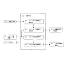
- FIG. 2 is a block diagram showing a configuration of a control device of a cylinder lubricating device according to an embodiment of the present invention.
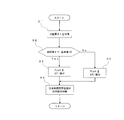
- FIG. 3 is a flowchart illustrating a control procedure of control of cylinder oil supply by the controller of FIG.
- FIG. 4 is a flowchart illustrating a control procedure of the supply control of the TBN regulator by the control device of FIG.
- FIG. 1 is a schematic view showing the configuration of a cylinder oiling apparatus according to an embodiment of the present invention and the configuration of a main part of an internal combustion engine.
- FIG. 2 is a block diagram showing a configuration of a control device of a cylinder lubricating device according to an embodiment of the present invention.
- FIG. 3 is a flowchart illustrating a control procedure of control of cylinder oil supply by the controller of FIG.
- FIG. 4 is a flowchart illustrating a control procedure of the supply control of the TBN regulator by the control device of FIG.
- the internal combustion engine injects fuel into a combustion chamber 15 defined by a cylinder liner 1, a piston 2 having a piston ring 2 a fitted on the outer peripheral surface, and the cylinder liner 1. And a valve 16.
- the piston 2 reciprocates while bringing a piston ring 2 a into sliding contact with a sliding surface (a cylinder liner sliding surface, hereinafter also referred to as a cylinder sliding surface) 1 a of the cylinder liner 1.
- the internal combustion engine is provided with a cylinder lubricating device (pH adjusting device for the cylinder liner sliding surface of the internal combustion engine) 50 for supplying (lubricating) lubricating oil (hereinafter also referred to as cylinder oil) to the cylinder sliding surface 1a. .
- the cylinder oil supply device 50 includes an oil supply tank 3 for storing cylinder oil, an oil supply pump (lubricating oil supply means) 4 for supplying cylinder oil stored in the oil supply tank 3 to the cylinder liner 1, and the cylinder liner 1.
- Cylinder oil flow sensor (lubricating oil flow detecting means) 5 for detecting the flow of cylinder oil supplied
- solenoid valve for oil amount adjustment for adjusting the flow of cylinder oil supplied to the cylinder liner 1 (lubricant oil supply amount adjustment Means 6)
- An oil supply section 7 opened in the cylinder sliding surface 1a, and an oil supply pipe (lubricating oil supply path) 8 connecting the oil supply tank 3 and the oil supply section 7 are configured.
- the oil feeding pump 4, the cylinder oil flow rate sensor 5, and the oil amount adjusting solenoid valve 6 are disposed in this order from the upstream side in the flow direction of the cylinder oil.
- the oil amount adjusting solenoid valve 6 is normally closed by a biasing means such as a spring and is closed. When an on signal is received from the control means 20 described later, the internal solenoid is excited to open. The oil amount adjusting solenoid valve 6 adjusts the flow rate of the cylinder oil in accordance with the control command of the control means 20.
- the cylinder lubricating device 50 further includes a TBN regulator tank 9 for storing the TBN regulator (pH regulator), and a pump for the TBN regulator for delivering the TBN regulator stored in the TBN regulator tank 9 (regulator Supplying means) 10, a solenoid valve for TBN adjusting agent (adjusting agent supply amount adjusting means) 11 for adjusting the flow rate of the TBN adjusting agent, a TBN supply pipe (adjusting TBN adjusting agent tank 9 and the oil pipe 8) (Agent flow path) 12 is configured.
- the TBN adjusting agent is supplied from the TBN adjusting agent pump 10 to the cylinder sliding face 1 a via the TBN supply pipe 12 and the oil supply pipe 8. That is, the regulator supply passage of the present invention connecting the TBN regulator pump 10 and the cylinder liner sliding surface 1 a is constituted by the TBN supply pipe 12 and the oil feeding pipe 8.
- the TBN regulator solenoid valve 11 is disposed downstream of the TBN regulator pump 10, the TBN regulator solenoid valve 11 may be disposed upstream of the TBN regulator pump 10.
- the TBN adjuster solenoid valve 11 is configured in the same manner as the oil amount adjustment solenoid valve 6, and thus the description thereof is omitted.
- the cylinder lubricating device 50 includes an oil film thickness meter (oil film thickness detection means) 13 and a pH meter (pH detection means) 14.
- the oil film thickness meter 13 and the pH meter 14 are attached to the cylinder liner 1 respectively.
- the oil film thickness meter 13 detects the oil film thickness t of the lubricating oil formed on the cylinder sliding surface 1a.
- the oil film thickness gauge 13 detects the oil film thickness by, for example, detecting the conduction of the piston ring 21 or optically detecting the distance to the oil film.
- the pH meter 14 detects the pH value of the cylinder sliding surface 1a.
- control means 20 sets a cylinder oil supply amount setting unit (lubricant oil supply amount setting unit) 21, a cylinder oil solenoid valve control unit (lubricant oil adjustment means control unit) 22, and a TBN supply amount setting. It is comprised including a part (regulator supply amount setting part) 23 and a TBN solenoid valve control part (regulator adjustment means control part) 24.
- the cylinder oil supply amount setting unit 21 acquires the oil film thickness t of the lubricating oil on the cylinder sliding surface 1a from the oil film thickness meter 13, and cylinder oil based on the comparison between the oil film thickness t and the reference value t0.
- the set flow rate FLset which is the supply amount per unit time, is determined.
- the reference value t0 is set to a value at which the performance of the internal combustion engine and the lubricating performance between the cylinder sliding surface 1a and the piston 2 are obtained satisfactorily. That is, when the oil film thickness t is larger than the reference value t0, the cylinder oil supply amount setting unit 21 sets a large amount of lubricating oil to the combustion chamber 15 and adversely affects the performance of the internal combustion engine.
- the flow rate FLset is decreased to thin the oil film thickness t, and when the oil film thickness t is less than the reference value t0, the lubricating performance is not sufficiently obtained, so the set flow rate FLset is increased to increase the oil film thickness t. .
- the cylinder oil solenoid valve control unit 22 feeds back the cylinder oil flow rate FL detected by the cylinder oil flow rate sensor 5 so that the actual cylinder oil flow rate becomes the set flow rate FLset set by the cylinder oil supply amount setting unit 21. While controlling the operation of the oil amount adjustment solenoid valve 6.
- the TBN supply amount setting unit 23 acquires the pH value Pc of the cylinder sliding surface 1 a from the pH meter 14 and acquires the cylinder oil flow rate FL from the cylinder oil flow rate sensor 5 to obtain a pH value Pc and a cylinder oil flow rate FL. Based on the set flow rate FTset, which is the supply amount per unit time of the TBN regulator, is determined. This is due to the following reason. That is, if fuel contains a large amount of sulfur, acid corrosion may occur on the cylinder liner sliding surface 1a. Therefore, the TBN regulator is supplied to the cylinder liner sliding surface 1a to adjust the pH value of the cylinder liner sliding surface 1a.
- the TBN supply amount setting unit 23 lowers the set flow rate FTset because there is a possibility that Ca component (CaO) may be precipitated due to the excessiveness of TBN.
- the set flow rate FTset is increased because there is a possibility of acid corrosion.
- the reference value P0 is set to a value that can properly neutralize the cylinder sliding surface 1a.
- the TBN supply amount setting unit 23 properly obtains the effect of the TBN regulator regardless of the cylinder oil flow rate FL (that is, the ratio of the TBN regulator to the cylinder oil flow rate FL is in an appropriate range).
- the set flow rate FTset is set according to the cylinder oil flow rate FL. That is, the set flow rate FTset is set higher as the cylinder oil flow rate FL is higher, and the set flow rate FTset is set lower as the cylinder oil flow rate FL is smaller.
- the TBN supply amount setting unit 23 changes the cylinder oil flow rate (detection value) FL acquired from the cylinder oil flow rate sensor 5, and sets the flow rate FLset or oil film thickness of cylinder oil acquired from the cylinder oil supply amount setting unit 21.
- the set flow rate FTset of the TBN regulator may be determined based on the oil film thickness t obtained from the total 13.
- the TBN solenoid valve control unit 24 performs open loop control of the operation of the TBN regulator solenoid valve 11 so as to achieve the set flow rate FTset set by the TBN supply amount setting unit 23.
- step S2 the acquired oil film thickness t is compared with a reference value t0. If the oil film thickness t is larger than the reference value t0, the process proceeds to step S3. For example, the correction amount ⁇ FL is calculated based on the difference between the oil film thickness t and the reference value t0. A value obtained by subtracting the amount ⁇ FL is set as a new set flow rate FLset, and the process proceeds to step S4. If the oil film thickness t is less than or equal to the reference value t0 in step S2, the process proceeds to step S5.
- the correction amount ⁇ FL is calculated based on the difference between the oil film thickness t and the reference value t0. A value obtained by adding this correction amount ⁇ FL to the new set flow rate FLset is set, and the process proceeds to step S5.
- step S5 the operation of the oil amount adjustment solenoid valve 6 is controlled so that the set amount FLset is reached.
- step S11 the pH value Pc of the cylinder sliding surface 1a is acquired from the pH meter 14 in step S11, the cylinder oil flow rate FL is acquired from the cylinder oil flow sensor 5 in step S12, and the process proceeds to step S13.
- step S13 the acquired pH value Pc is compared with the reference value P0. If the pH value Pc is larger than the reference value P0, the process proceeds to step S14.
- step S14 for example, the correction amount ⁇ FT is calculated based on the difference between the pH value Pc and the reference value P0, and the acquired cylinder oil flow rate FL, and the correction amount ⁇ FT is calculated from the current set flow rate FTset of the TBN adjusting agent.
- step S15 Is set as a new set flow rate FTset, and the process proceeds to step S15.
- the pH value Pc is equal to or less than the reference value P0 as a result of the comparison in step S13
- the process proceeds to step S16.
- step S16 for example, the correction amount ⁇ FT is calculated based on the difference between the pH value Pc and the reference value P0 and the cylinder oil flow rate FL, and the correction amount ⁇ FT is added to the current set flow rate FTset of the TBN adjustment agent The value is set as a new set flow rate FTset, and the process proceeds to step S15.
- step S15 the operation of the TBN regulator solenoid valve 11 is controlled so that the set amount FTset is obtained.
- the cylinder sliding surface pH value detected by the pH meter 14 is compared with the reference value P0 to obtain the cylinder Since the amount of supply of the TBN adjusting agent supplied to the oil is adjusted, the pH value Pc of the cylinder sliding surface 1a converges to the vicinity of the reference value P0 (within the appropriate range). Therefore, regardless of the amount of sulfur (S) contained in the fuel, the pH value of the cylinder sliding surface 1a can be maintained in the appropriate range.
- the amount of cylinder oil supplied to the cylinder sliding surface 1a is adjusted by comparing the oil film thickness t detected by the oil film thickness meter 13 with the reference value t0, the oil film thickness t is It converges to the vicinity of the reference value t0 (within the appropriate range). Therefore, the lubricating performance between the cylinder liner 1a and the piston 2 can be maintained well.
- the ratio of the TBN adjustment agent supply rate to the cylinder oil flow rate FL is set in an appropriate range. can do.
- the amount of cylinder oil supplied is increased or decreased by comparing the oil film thickness t detected by the oil film thickness meter 13 with the reference value t0.
- the present invention is not limited to this.
- the amount of cylinder oil supplied is decreased.
- the amount of cylinder oil supplied may be increased when the distance t is smaller than the reference range.
- the amount of supply of the TBN adjusting agent is increased or decreased based on the comparison between the pH value Pc of the cylinder sliding surface 1a detected by the pH meter 14 and the reference value P0. I will not. For example, when the pH value Pc deviates to the large side from the reference range (the range in which the cylinder sliding surface 1a can be properly neutralized), the supply amount of the TBN adjusting agent is decreased to lower the pH value Pc to the small side. If it deviates, the supply amount of the TBN regulator may be increased.
- the lubricating oil supply amount adjusting means is constituted by the oil amount adjusting solenoid valve 6, and the adjusting agent supply amount adjusting means is constituted by the TBN adjusting agent solenoid valve 11.
- the oil supply pump 4 and TBN adjustment A pump having a variable flow rate may be adopted as the agent pump 10.
- the oil amount adjusting solenoid valve 6 and the TBN adjusting agent solenoid valve 11 become unnecessary, and the oil feeding pump 4 serves as the lubricating oil supply means and the lubricating oil supply amount adjusting means, and the TBN adjusting agent pump 10 will be used as both the regulator feeding means and the regulator supply amount adjusting means.
- the TBN solenoid valve control unit 24 performs open loop control of the operation of the TBN regulator solenoid valve 11 so as to achieve the set flow rate FTset set by the TBN supply amount setting unit 23.
- the TBN regulator solenoid valve 11 may be subjected to feedback control so as to achieve the flow rate FTset.
- a TBN regulator flow sensor 25 is interposed in the TBN supply pipe 12, and the TBN solenoid valve control unit 24 detects the detection result of the TBN regulator flow sensor 25. Based on the above, the operation of the TBN adjusting agent solenoid valve 11 is controlled so that the flow rate of the TBN adjusting agent becomes the set flow rate FTset.
- the TBN modifier is supplied to the cylinder sliding surface 1a through the oil supply pipe 8 (that is, mixed with the lubricating oil).
- the TBN modifier is a TBN modifier It is also possible to supply the cylinder sliding surface 1a directly from the pump 10 (in other words, the downstream end of the TBN supply pipe 12 is directly connected to the cylinder sliding surface 1a and only the TBN supply pipe 12 is used)
Landscapes
- Engineering & Computer Science (AREA)
- General Engineering & Computer Science (AREA)
- Mechanical Engineering (AREA)
- Lubrication Of Internal Combustion Engines (AREA)
- Lubrication Details And Ventilation Of Internal Combustion Engines (AREA)
Abstract
燃料に含まれる硫黄分の多少にかかわらず、シリンダ摺動面のpH値を適正範囲に維持できるようにした、シリンダライナ摺動面のpH調整装置,内燃機関のシリンダ注油装置及び内燃機関を提供する。 内燃機関のシリンダライナ摺動面のpH値を検出するpH検出手段(14)と、pH調整剤を送給する調整剤送給手段と、調整剤供給路と、pH調整剤の供給量を調整する調整剤供給量調整手段(11)と、制御手段(20)とを備え、前記制御手段(20)は、pH検出手段(14)の検出結果に基づいて、前記摺動面のpH値が適正範囲に収まるように前記pH調整剤の供給量を設定する調整剤供給量設定部(23)と、調整剤供給量設定部(23)により設定された前記供給量の前記pH調整剤を前記摺動面に供給できるように、前記調整剤供給量調整手段(11)の作動を制御する調整剤調整手段制御部(24)とを備える。
Description
本発明は、内燃機関のシリンダライナ摺動面のpH調整装置,内燃機関のシリンダ注油装置及び内燃機関に関する。
舶用エンジンでは、ピストンリングが摺接するシリンダライナの摺動面に、シリンダ潤滑油(以下シリンダ油という)が供給されて、この摺動面が潤滑されている。
舶用エンジンでは、通常、燃料油として重油が用いられている。重油には硫黄分等の酸性物質が含まれているため、シリンダライナの摺動面が酸性腐食する場合がある。この酸性腐食の発生を防止するため、舶用エンジンでは、シリンダ油に塩基性成分を有するものが使用され酸性物質が中和されるようにしている。
しかしながら、重油と、重油以外の硫黄分(酸性物質)の少ない燃料(以下、低S分燃料という)とを切り替えて使用する舶用エンジンでは、燃料に応じてシリンダ油を選定するのが困難である。つまり、重油にあわせて全塩基化(以下、TBNという)が高めのシリンダ油が使用されると、低S分燃料の使用時には、TBNの過大化に伴ってCa分が析出し、この析出がシリンダライナに悪影響を及ぼす一方、低S分燃料にあわせてTBNが低めのシリンダ油が使用されると、重油の使用時には、シリンダ油が酸性物質を中和しきれず、シリンダライナの酸性腐食が進行する。
そこで、特許文献1には、TBNが異なるシリンダ油を収容した複数のタンクを備え、シリンダライナ摺動面のpH値を検出し、このpH値の検出値と基準値とを比較し、この比較結果によって、シリンダライナへ供給するタンクを切り替えて(すなわちTBNの異なるシリンダ油を使い分けて)シリンダライナ摺動面のpH値を基準値に近づける注油装置が記載されている。
また、特許文献2には、燃料の硫黄含有量又は燃料の硫黄含有量に相関する使用済み潤滑剤のBN値(残留BN値)に基づいて、シリンダライナへ供給する潤滑剤の量を調整することで、シリンダライナの研磨ひいては腐食を防止する内燃機関が記載されている。
特許文献1に記載された装置は、TBNの異なるシリンダ油を切り替えて使用するものであり、連続的にTBNを変更できない。このため、使用する燃料に適合するシリンダ油が用意されていない場合にはこの燃料に対応できない。
TBNを小刻みに変更してシリンダ油の種類を増やすことにより、対応できる燃料の範囲を広げることも考えられる。しかし、TBNが異なるシリンダ油の種類を増やすことはタンクの数を増やすことであり、コスト増や、タンクを切り替えるための構造の複雑化を招く。また、TBNの異なるシリンダ油の種類を増やしてもTBNを連続的に変化させることはできないので、燃料の種類に拘わらず最適なTBNのシリンダ油を用意することは現実的には極めて困難である。
TBNを小刻みに変更してシリンダ油の種類を増やすことにより、対応できる燃料の範囲を広げることも考えられる。しかし、TBNが異なるシリンダ油の種類を増やすことはタンクの数を増やすことであり、コスト増や、タンクを切り替えるための構造の複雑化を招く。また、TBNの異なるシリンダ油の種類を増やしてもTBNを連続的に変化させることはできないので、燃料の種類に拘わらず最適なTBNのシリンダ油を用意することは現実的には極めて困難である。
特許文献2に記載された内燃機関では、シリンダへの潤滑剤の供給量を調整することによりシリンダライナの腐食を防止するものであるが、潤滑剤の供給量の調整範囲には限界がある。つまり、潤滑量は、少なすぎるとシリンダライナの摺動面の潤滑性を確保できず、多すぎると燃焼室に潤滑油が多量にかき上げられて内燃機関の性能に悪影響を与えてしまう。このため、この内燃機関は、潤滑量の調整可能範囲を超えるような硫黄含有量の燃料に対応することができない。
本発明は、燃料に含まれる硫黄分の多少にかかわらず、シリンダ摺動面のpH値を適正範囲に維持できるようにした、内燃機関のシリンダライナ摺動面のpH調整装置,内燃機関のシリンダ注油装置及び内燃機関を提供することを目的とする。
(1)上記の目的を達成するために、本発明の内燃機関のシリンダライナ摺動面のpH調整装置は、内燃機関のシリンダライナの摺動面のpH値を検出するpH検出手段と、pH調整剤を送給する調整剤送給手段と、前記調整剤送給手段と前記摺動面とを接続する調整剤供給路と、前記摺動面へのpH調整剤の供給量を調整する調整剤供給量調整手段と、制御手段とを備え、前記制御手段は、前記pH検出手段の検出結果に基づいて、前記摺動面のpH値が適正範囲に収まるように前記pH調整剤の供給量を設定する調整剤供給量設定部と、前記調整剤供給量設定部により設定された前記供給量の前記pH調整剤を前記摺動面に供給できるように、前記調整剤供給量調整手段の作動を制御する調整剤調整手段制御部とを備えたことを特徴としている。
(2)上記の目的を達成するために、本発明の内燃機関のシリンダ注油装置は、内燃機関のシリンダライナの摺動面に潤滑油を供給する内燃機関のシリンダ注油装置であって、前記潤滑油を送給する潤滑油送給手段と、前記潤滑油送給手段と前記摺動面とを接続する潤滑油供給路と、前記摺動面のpH値を検出するpH検出手段と、pH調整剤を送給する調整剤送給手段と、前記調整剤送給手段と前記潤滑油供給路とを接続する調整剤流路と、前記潤滑油供給路へのpH調整剤の供給量を調整する調整剤供給量調整手段と、制御手段とを備え、前記制御手段は、前記pH検出手段の検出結果に基づいて、前記摺動面のpH値が適正範囲に収まるように前記pH調整剤の供給量を設定する調整剤供給量設定部と、前記調整剤供給量設定部により設定された前記供給量の前記pH調整剤を前記摺動面に供給できるように、前記調整剤供給量調整手段の作動を制御する調整剤調整手段制御部とを備えたことを特徴としている。
(3)前記摺動面への前記潤滑油の供給量を調整する潤滑油供給量調整手段と、前記摺動面に形成された前記潤滑油の油膜厚さを検出する油膜厚さ検出手段とを備え、前記制御手段は、前記油膜厚さ検出手段の検出結果に基づいて、前記油膜厚さが適正範囲に収まるように前記潤滑油の供給量を設定する潤滑油供給量設定部と、前記潤滑油供給量設定部により設定された前記供給量の前記潤滑油を前記摺動面に供給できるように、前記潤滑油供給量調整手段を制御する、潤滑油調整手段制御部とを有することが好ましい。
(4)前記潤滑油供給路に設けられた潤滑油流量検出手段を備え、前記調整剤供給量設定部は、前記pH検出手段の検出結果と前記潤滑油流量検出手段の検出結果とに基づいて前記pH調整剤の供給量を設定することが好ましい。
(5)上記の目的を達成するために、本発明の内燃機関は、(1)の内燃機関のシリンダライナ摺動面のpH調整装置又は(2)~(4)の何れかに記載の内燃機関のシリンダ注油装置を備えたことを特徴としている。
本発明によれば、pH検出手段により検出されたシリンダライナの摺動面のpH値が適正範囲に収まるようにpH調整剤の供給量が調整されるので、燃料に含まれる硫黄分の多少にかかわらず、シリンダライナの摺動面のpH値を適正範囲に維持することができる。
以下、図面を参照して、本発明の実施の形態について説明する。
図1は、本発明の一実施形態のシリンダ注油装置の構成及び内燃機関の要部の構成を示す模式図である。
図2は、本発明の一実施形態のシリンダ注油装置の制御装置の構成を示すブロック図である。
図3は、図2の制御装置によるシリンダ油の供給量制御の制御手順を例示するフローチャートである。
図4は、図2の制御装置によるTBN調整剤の供給量制御の制御手順を例示するフローチャートである。
なお、以下に示す実施形態はあくまでも例示に過ぎず、以下の実施形態で明示しない種々の変形や技術の適用を排除する意図はない。以下の実施形態の各構成は、それらの趣旨を逸脱しない範囲で種々変形して実施することができるとともに、必要に応じて取捨選択することができ、あるいは適宜組み合わせることが可能である。
図1は、本発明の一実施形態のシリンダ注油装置の構成及び内燃機関の要部の構成を示す模式図である。
図2は、本発明の一実施形態のシリンダ注油装置の制御装置の構成を示すブロック図である。
図3は、図2の制御装置によるシリンダ油の供給量制御の制御手順を例示するフローチャートである。
図4は、図2の制御装置によるTBN調整剤の供給量制御の制御手順を例示するフローチャートである。
なお、以下に示す実施形態はあくまでも例示に過ぎず、以下の実施形態で明示しない種々の変形や技術の適用を排除する意図はない。以下の実施形態の各構成は、それらの趣旨を逸脱しない範囲で種々変形して実施することができるとともに、必要に応じて取捨選択することができ、あるいは適宜組み合わせることが可能である。
[1.構成]
本発明に一実施形態としての舶用ディーゼルエンジン(以下、内燃機関という)の要部構成とこの内燃機関に備えられるシリンダ注油装置の構成を、図1を参照して説明する。
本発明に一実施形態としての舶用ディーゼルエンジン(以下、内燃機関という)の要部構成とこの内燃機関に備えられるシリンダ注油装置の構成を、図1を参照して説明する。
図1に示すように、内燃機関は、シリンダライナ1と、外周面にピストンリング2aが嵌めこまれたピストン2と、シリンダライナ1により画成される燃焼室15内に燃料を噴射する燃料噴射弁16とを備えている。ピストン2は、シリンダライナ1の摺動面(シリンダライナ摺動面、以下シリンダ摺動面ともいう)1aにピストンリング2aを摺接させながら往復動するようになっている。
内燃機関には、シリンダ摺動面1aに潤滑油(以下、シリンダ油ともいう)を供給(注油)するシリンダ注油装置(内燃機関のシリンダライナ摺動面のpH調整装置)50が備えられている。
内燃機関には、シリンダ摺動面1aに潤滑油(以下、シリンダ油ともいう)を供給(注油)するシリンダ注油装置(内燃機関のシリンダライナ摺動面のpH調整装置)50が備えられている。
シリンダ注油装置50は、シリンダ油を貯留する注油タンク3と、注油タンク3に貯留されたシリンダ油をシリンダライナ1へ送給する注油用ポンプ(潤滑油送給手段)4と、シリンダライナ1へ供給されるシリンダ油の流量を検出するシリンダ油流量センサ(潤滑油流量検出手段)5と、シリンダライナ1へ供給されるシリンダ油の流量を調整する注油量調整用電磁弁(潤滑油供給量調整手段)6と、シリンダ摺動面1aに開口する注油部7と、注油タンク3と注油部7とを接続する注油管(潤滑油供給路)8とを備えて構成されている。本実施形態では、注油用ポンプ4と、シリンダ油流量センサ5と、注油量調整用電磁弁6とは、シリンダ油の流通方向で上流側からこの順に配置されている。
注油量調整用電磁弁6は、通常はバネ等の付勢手段により付勢されて閉弁状態であり、後述する制御手段20からオン信号を受けると内部のソレノイドが励磁されて開弁する。注油量調整用電磁弁6は、制御手段20の制御指令に応じてシリンダ油の流量を調整する。
シリンダ注油装置50は、さらに、TBN調整剤(pH調整剤)を貯留するTBN調整剤タンク9と、TBN調整剤タンク9に貯留されたTBN調整剤を送給するTBN調整剤用ポンプ(調整剤送給手段)10と、TBN調整剤の流量を調整するTBN調整剤用電磁弁(調整剤供給量調整手段)11と、TBN調整剤タンク9と注油管8とを接続するTBN供給管(調整剤流路)12とを備えて構成されている。
TBN調整剤は、TBN調整剤用ポンプ10から、TBN供給管12と注油管8とを介してシリンダ摺動面1aへと供給されるようになっている。すなわち、TBN調整剤用ポンプ10とシリンダライナ摺動面1aとを接続する本発明の調整剤供給路が、TBN供給管12と注油管8とから構成されている。
本実施形態では、TBN調整剤用電磁弁11を、TBN調整剤用ポンプ10よりも下流側に配置しているが、TBN調整剤用ポンプ10よりも上流側に配置しても良い。
TBN調整剤用電磁弁11は、注油量調整用電磁弁6と同様に構成されているので説明を省略する。
本実施形態では、TBN調整剤用電磁弁11を、TBN調整剤用ポンプ10よりも下流側に配置しているが、TBN調整剤用ポンプ10よりも上流側に配置しても良い。
TBN調整剤用電磁弁11は、注油量調整用電磁弁6と同様に構成されているので説明を省略する。
さらに、シリンダ注油装置50は、油膜厚さ計(油膜厚さ検出手段)13及びpH計(pH検出手段)14を備えている。これらの油膜厚さ計13及びpH計14はそれぞれシリンダライナ1に取り付けられている。
油膜厚さ計13は、シリンダ摺動面1aに形成された潤滑油の油膜厚さtを検出する。油膜厚さ計13は、例えば、ピストンリング21の導通を検知することや、光学的に油膜までの距離を検知することで油膜厚さを検出する。pH計14は、シリンダ摺動面1aのpH値を検出する。
油膜厚さ計13は、シリンダ摺動面1aに形成された潤滑油の油膜厚さtを検出する。油膜厚さ計13は、例えば、ピストンリング21の導通を検知することや、光学的に油膜までの距離を検知することで油膜厚さを検出する。pH計14は、シリンダ摺動面1aのpH値を検出する。
[2.制御構成]
制御手段20の構成を、図2を参照して説明する。
制御手段20は、図2に示すように、シリンダ油供給量設定部(潤滑油供給量設定部)21と、シリンダ油電磁弁制御部(潤滑油調整手段制御部)22と、TBN供給量設定部(調整剤供給量設定部)23と、TBN電磁弁制御部(調整剤調整手段制御部)24とを備えて構成されている。
制御手段20の構成を、図2を参照して説明する。
制御手段20は、図2に示すように、シリンダ油供給量設定部(潤滑油供給量設定部)21と、シリンダ油電磁弁制御部(潤滑油調整手段制御部)22と、TBN供給量設定部(調整剤供給量設定部)23と、TBN電磁弁制御部(調整剤調整手段制御部)24とを備えて構成されている。
シリンダ油供給量設定部21は、油膜厚さ計13から、シリンダ摺動面1aの潤滑油の油膜厚さtを取得し、この油膜厚さtと基準値t0との比較に基づいてシリンダ油の単位時間当たりの供給量である設定流量FLsetを決定する。基準値t0は、内燃機関の性能と、シリンダ摺動面1aとピストン2との間の潤滑性能とが良好に得られ値に設定されている。
つまり、シリンダ油供給量設定部21は、油膜厚さtが基準値t0よりも大きい場合には、潤滑油が多量に燃焼室15にかき上げられて内燃機関の性能に悪影響を及ぼすので、設定流量FLsetを低下させて油膜厚さtを薄くし、油膜厚さtが基準値t0以下の場合には潤滑性能が十分に得られないので設定流量FLsetを増加して油膜厚さtを厚くする。
つまり、シリンダ油供給量設定部21は、油膜厚さtが基準値t0よりも大きい場合には、潤滑油が多量に燃焼室15にかき上げられて内燃機関の性能に悪影響を及ぼすので、設定流量FLsetを低下させて油膜厚さtを薄くし、油膜厚さtが基準値t0以下の場合には潤滑性能が十分に得られないので設定流量FLsetを増加して油膜厚さtを厚くする。
シリンダ油電磁弁制御部22は、実際のシリンダ油流量がシリンダ油供給量設定部21により設定された設定流量FLsetとなるように、シリンダ油流量センサ5により検出されたシリンダ油流量FLをフィードバックしながら注油量調整用電磁弁6の作動を制御する。
TBN供給量設定部23は、pH計14からシリンダ摺動面1aのpH値Pcを取得するとともにシリンダ油流量センサ5からシリンダ油流量FLを取得して、pH値Pcとシリンダ油流量FLとに基づいてTBN調整剤の単位時間当たりの供給量である設定流量FTsetを決定する。
これは次の理由による。つまり、燃料に硫黄分が多く含まれるとシリンダライナ摺動面1aに酸性腐食が生じるおそれがあるため、シリンダライナ摺動面1aにTBN調整剤を供給してシリンダライナ摺動面1aのpH値Pcを調整する必要がある一方、TBN調整剤を過剰に供給してしまうとCa分(CaO)が析出するおそれがある。そこで、TBN供給量設定部23は、pH値Pcが基準値P0よりも大きい場合には、TBNの過大化によるCa分(CaO)が析出するおそれがあるので、設定流量FTsetを低下させ、pH値Pcが基準値P0以下の場合には酸性腐食のおそれがあるとして設定流量FTsetを増加する。なお、基準値P0は、シリンダ摺動面1aを適正に中和できる値に設定されている。
これは次の理由による。つまり、燃料に硫黄分が多く含まれるとシリンダライナ摺動面1aに酸性腐食が生じるおそれがあるため、シリンダライナ摺動面1aにTBN調整剤を供給してシリンダライナ摺動面1aのpH値Pcを調整する必要がある一方、TBN調整剤を過剰に供給してしまうとCa分(CaO)が析出するおそれがある。そこで、TBN供給量設定部23は、pH値Pcが基準値P0よりも大きい場合には、TBNの過大化によるCa分(CaO)が析出するおそれがあるので、設定流量FTsetを低下させ、pH値Pcが基準値P0以下の場合には酸性腐食のおそれがあるとして設定流量FTsetを増加する。なお、基準値P0は、シリンダ摺動面1aを適正に中和できる値に設定されている。
また、TBN供給量設定部23は、シリンダ油流量FLにかかわらずTBN調整剤の効果が適切に得られるように(つまりシリンダ油流量FLに対するTBN調整剤の比率が適切な範囲となるように)シリンダ油流量FLに応じて設定流量FTsetを設定する。つまり、シリンダ油流量FLが高いほど設定流量FTsetを高めに設定し、シリンダ油流量FLが小さいほど設定流量FTsetを低めに設定する。
なお、TBN供給量設定部23は、シリンダ油流量センサ5から取得したシリンダ油流量(検出値)FLに替えて、シリンダ油供給量設定部21から取得したシリンダ油の設定流量FLset又は油膜厚さ計13から取得した油膜厚さtに基づいてTBN調整剤の設定流量FTsetを決定しても良い。
TBN電磁弁制御部24は、TBN供給量設定部23により設定された設定流量FTsetとなるようにTBN調整剤用電磁弁11の作動をオープンループ制御する。
[3.フローチャート]
本発明の一実施形態に係るシリンダ油の供給量制御及びTBN調整剤の供給量制御について図3及び図4を参照して説明する。シリンダ油の供給量制御及びTBN調整剤の供給量制御は、それぞれ独立して予め設定された所定の周期で繰り返し実施される。
本発明の一実施形態に係るシリンダ油の供給量制御及びTBN調整剤の供給量制御について図3及び図4を参照して説明する。シリンダ油の供給量制御及びTBN調整剤の供給量制御は、それぞれ独立して予め設定された所定の周期で繰り返し実施される。
先ず、シリンダ油の供給量制御について説明する。
図3に示すように、ステップS1において油膜厚さ計13から油膜厚さtが取得され、ステップS2に進む。ステップS2では、取得した油膜厚さtと、基準値t0との比較が行われる。油膜厚さtが基準値t0よりも大きい場合には、ステップS3に進み、例えば油膜厚さtと基準値t0との差分に基づいて補正量ΔFLが算出され、現在の設定流量FLsetからこの補正量ΔFLを減算した値が、新たな設定流量FLsetとされて、ステップS4に進む。
ステップS2で、油膜厚さtが基準値t0以下の場合には、ステップS5に進み、例えば油膜厚さtと基準値t0との差分に基づいて補正量ΔFLが算出され、現在の設定流量FLsetにこの補正量ΔFLを加算した値が、新たな設定流量FLsetとされて、ステップS5に進む。
ステップS5では、この設定量FLsetになるように注油量調整用電磁弁6の作動が制御される。
図3に示すように、ステップS1において油膜厚さ計13から油膜厚さtが取得され、ステップS2に進む。ステップS2では、取得した油膜厚さtと、基準値t0との比較が行われる。油膜厚さtが基準値t0よりも大きい場合には、ステップS3に進み、例えば油膜厚さtと基準値t0との差分に基づいて補正量ΔFLが算出され、現在の設定流量FLsetからこの補正量ΔFLを減算した値が、新たな設定流量FLsetとされて、ステップS4に進む。
ステップS2で、油膜厚さtが基準値t0以下の場合には、ステップS5に進み、例えば油膜厚さtと基準値t0との差分に基づいて補正量ΔFLが算出され、現在の設定流量FLsetにこの補正量ΔFLを加算した値が、新たな設定流量FLsetとされて、ステップS5に進む。
ステップS5では、この設定量FLsetになるように注油量調整用電磁弁6の作動が制御される。
次に、TBN調整剤の供給量制御について説明する。図4に示すように、ステップS11においてpH計14からシリンダ摺動面1aのpH値Pcが取得され、ステップS12においてシリンダ油流量センサ5からシリンダ油流量FLが取得されて、ステップS13に進む。
ステップS13では、取得したpH値Pcと基準値P0との比較が行われ、pH値Pcが基準値P0よりも大きい場合には、ステップS14に進む。
ステップS14では、例えば、pH値Pcと基準値P0との差分と、取得したシリンダ油流量FLとに基づいて補正量ΔFTが算出され、現在のTBN調整剤の設定流量FTsetから、この補正量ΔFTを減算した値が、新たな設定流量FTsetとされて、ステップS15に進む。
ステップS13での比較の結果、pH値Pcが基準値P0以下の場合には、ステップS16に進む。ステップS16では、例えば、pH値Pcと基準値P0との差分と、シリンダ油流量FLとに基づいて補正量ΔFTが算出され、現在のTBN調整剤の設定流量FTsetにこの補正量ΔFTを加算した値が、新たな設定流量FTsetとされて、ステップS15に進む。
ステップS15では、この設定量FTsetになるようにTBN調整剤用電磁弁11の作動が制御される。
ステップS13では、取得したpH値Pcと基準値P0との比較が行われ、pH値Pcが基準値P0よりも大きい場合には、ステップS14に進む。
ステップS14では、例えば、pH値Pcと基準値P0との差分と、取得したシリンダ油流量FLとに基づいて補正量ΔFTが算出され、現在のTBN調整剤の設定流量FTsetから、この補正量ΔFTを減算した値が、新たな設定流量FTsetとされて、ステップS15に進む。
ステップS13での比較の結果、pH値Pcが基準値P0以下の場合には、ステップS16に進む。ステップS16では、例えば、pH値Pcと基準値P0との差分と、シリンダ油流量FLとに基づいて補正量ΔFTが算出され、現在のTBN調整剤の設定流量FTsetにこの補正量ΔFTを加算した値が、新たな設定流量FTsetとされて、ステップS15に進む。
ステップS15では、この設定量FTsetになるようにTBN調整剤用電磁弁11の作動が制御される。
本発明の一実施形態のシリンダ注油装置、及び、このシリンダ注油装置を備えた内燃機関によれば、pH計14により検出されたシリンダ摺動面のpH値と基準値P0との比較により、シリンダ油に供給されるTBN調整剤の供給量が調整されるので、シリンダ摺動面1aのpH値Pcが基準値P0の近傍に収束する(適正範囲内に収まる)。したがって、燃料に含まれるS分(硫黄分)の多少にかかわらず、シリンダ摺動面1aのpH値を適正範囲に維持することができる。
また、油膜厚さ計13により検出された油膜厚さtと、基準値t0との比較により、シリンダ摺動面1aに供給されるシリンダ油の供給量が調整されるので、油膜厚さtが基準値t0の近傍に収束する(適正範囲内に収まる)。したがって、シリンダライナ1aとピストン2との間の潤滑性能を良好に維持できる。
さらに、TBN調整剤の供給量は、シリンダ油流量センサ5によって検出されたシリンダ油流量FLに応じて決定されるので、シリンダ油流量FLに対するTBN調整剤の供給量の割合を適切な範囲に設定することができる。
[4.その他]
(1)上記実施形態では、油膜厚さ計13により検出された油膜厚さtと基準値t0との比較によりシリンダ油の供給量を増減させていたが、これに限定されない。例えば、油膜厚さtが基準範囲(シリンダ摺動面1aとピストン2との間の潤滑性能が良好に得られる範囲)から大きい側に外れる場合にはシリンダ油の供給量を減少させ、油膜厚さtが基準範囲から小さい側に外れる場合にはシリンダ油の供給量を増大させるようにしても良い。
(1)上記実施形態では、油膜厚さ計13により検出された油膜厚さtと基準値t0との比較によりシリンダ油の供給量を増減させていたが、これに限定されない。例えば、油膜厚さtが基準範囲(シリンダ摺動面1aとピストン2との間の潤滑性能が良好に得られる範囲)から大きい側に外れる場合にはシリンダ油の供給量を減少させ、油膜厚さtが基準範囲から小さい側に外れる場合にはシリンダ油の供給量を増大させるようにしても良い。
(2)上記実施形態では、pH計14により検出されたシリンダ摺動面1aのpH値Pcと基準値P0との比較に基づいてTBN調整剤の供給量を増減させていたが、これに限定されない。例えば、pH値Pcが基準範囲(シリンダ摺動面1aを適正に中和できる範囲)から大きい側に外れる場合にはTBN調整剤の供給量を減少させ、pH値Pcが基準範囲から小さい側に外れる場合にはTBN調整剤の供給量を増大させるようにしても良い。
(3)上記実施形態では、潤滑油供給量調整手段を注油量調整用電磁弁6により、調整剤供給量調整手段をTBN調整剤用電磁弁11により構成したが、注油用ポンプ4やTBN調整剤用ポンプ10に流量可変のポンプを採用しても良い。この場合、注油量調整用電磁弁6及びTBN調整剤用電磁弁11は不要となり、注油用ポンプ4が、潤滑油送給手段と潤滑油供給量調整手段とを兼用し、TBN調整剤用ポンプ10が調整剤送給手段と調整剤供給量調整手段とを兼用することとなる。
(4)上記実施形態では、TBN電磁弁制御部24は、TBN供給量設定部23により設定された設定流量FTsetとなるようにTBN調整剤用電磁弁11の作動をオープンループ制御したが、設定流量FTsetとなるようにTBN調整剤用電磁弁11をフィードバック制御するようにしても良い。具体的には、図1に二点鎖線で示すように、TBN供給管12にTBN調整剤流量センサ25を介装し、TBN電磁弁制御部24が、このTBN調整剤流量センサ25の検出結果に基づいて、TBN調整剤の流量が設定流量FTsetとなるようにTBN調整剤用電磁弁11の作動を制御する。
(5)上記実施形態では、TBN調整剤を、注油管8を介して(つまり潤滑油と混合して)シリンダ摺動面1aへと供給するようにしたが、TBN調整剤を、TBN調整剤用ポンプ10から直接シリンダ摺動面1aへと供給するようにしても良い(換言すれば、TBN供給管12の下流端をシリンダ摺動面1aに直接接続してTBN供給管12のみにより本発明の調整剤供給路を構成しても良い)。
(5)上記実施形態では、TBN調整剤を、注油管8を介して(つまり潤滑油と混合して)シリンダ摺動面1aへと供給するようにしたが、TBN調整剤を、TBN調整剤用ポンプ10から直接シリンダ摺動面1aへと供給するようにしても良い(換言すれば、TBN供給管12の下流端をシリンダ摺動面1aに直接接続してTBN供給管12のみにより本発明の調整剤供給路を構成しても良い)。
1 シリンダライナ
1a 摺動面(シリンダ摺動面)
2 ピストン
2a ピストンリング
4 注油用ポンプ(潤滑油送給手段)
5 シリンダ油流量センサ(潤滑油流量検出手段)
6 注油量調整用電磁弁(潤滑油供給量調整手段)
8 注油管(潤滑油供給路)
10 TBN調整剤用ポンプ(調整剤送給手段)
11 TBN調整剤用電磁弁(調整剤供給量調整手段)
12 TBN供給管(調整剤流路)
13 油膜厚さ計(油膜厚さ検出手段)
14 pH計(pH検出手段)
16 燃料噴射弁
20 制御手段
21 シリンダ油供給量設定部(潤滑油供給量設定部)
22 シリンダ油電磁弁制御部(潤滑油調整手段制御部)
23 TBN供給量設定部(調整剤供給量設定部)
24 TBN電磁弁制御部(調整剤調整手段制御部)
25 TBN調整剤流量センサ
50 シリンダ注油装置(内燃機関のシリンダライナ摺動面のpH調整装置)
FL シリンダ油流量
FLset シリンダ油の設定流量
ΔFL FLsetの補正量
FT TBN調整剤流量
FTset TBN調整剤の設定流量
ΔFT FTsetの補正量
Pc シリンダ摺動面1aのpH値
P0 シリンダ摺動面1aのpH値の基準値
t 油膜厚さ
t0 油膜厚さtの基準値
1a 摺動面(シリンダ摺動面)
2 ピストン
2a ピストンリング
4 注油用ポンプ(潤滑油送給手段)
5 シリンダ油流量センサ(潤滑油流量検出手段)
6 注油量調整用電磁弁(潤滑油供給量調整手段)
8 注油管(潤滑油供給路)
10 TBN調整剤用ポンプ(調整剤送給手段)
11 TBN調整剤用電磁弁(調整剤供給量調整手段)
12 TBN供給管(調整剤流路)
13 油膜厚さ計(油膜厚さ検出手段)
14 pH計(pH検出手段)
16 燃料噴射弁
20 制御手段
21 シリンダ油供給量設定部(潤滑油供給量設定部)
22 シリンダ油電磁弁制御部(潤滑油調整手段制御部)
23 TBN供給量設定部(調整剤供給量設定部)
24 TBN電磁弁制御部(調整剤調整手段制御部)
25 TBN調整剤流量センサ
50 シリンダ注油装置(内燃機関のシリンダライナ摺動面のpH調整装置)
FL シリンダ油流量
FLset シリンダ油の設定流量
ΔFL FLsetの補正量
FT TBN調整剤流量
FTset TBN調整剤の設定流量
ΔFT FTsetの補正量
Pc シリンダ摺動面1aのpH値
P0 シリンダ摺動面1aのpH値の基準値
t 油膜厚さ
t0 油膜厚さtの基準値
Claims (5)
- 内燃機関のシリンダライナの摺動面のpH値を検出するpH検出手段と、
pH調整剤を送給する調整剤送給手段と、
前記調整剤送給手段と前記摺動面とを接続する調整剤供給路と、
前記摺動面へのpH調整剤の供給量を調整する調整剤供給量調整手段と、
制御手段とを備え、
前記制御手段は、
前記pH検出手段の検出結果に基づいて、前記摺動面のpH値が適正範囲に収まるように前記pH調整剤の供給量を設定する調整剤供給量設定部と、
前記調整剤供給量設定部により設定された前記供給量の前記pH調整剤を前記摺動面に供給できるように、前記調整剤供給量調整手段の作動を制御する調整剤調整手段制御部とを備えた
ことを特徴とする、内燃機関のシリンダライナ摺動面のpH調整装置。 - 内燃機関のシリンダライナの摺動面に潤滑油を供給する内燃機関のシリンダ注油装置であって、
前記潤滑油を送給する潤滑油送給手段と、
前記潤滑油送給手段と前記摺動面とを接続する潤滑油供給路と、
前記摺動面のpH値を検出するpH検出手段と、
pH調整剤を送給する調整剤送給手段と、
前記調整剤送給手段と前記潤滑油供給路とを接続する調整剤流路と、
前記潤滑油供給路へのpH調整剤の供給量を調整する調整剤供給量調整手段と、
制御手段とを備え、
前記制御手段は、
前記pH検出手段の検出結果に基づいて、前記摺動面のpH値が適正範囲に収まるように前記pH調整剤の供給量を設定する調整剤供給量設定部と、
前記調整剤供給量設定部により設定された前記供給量の前記pH調整剤を前記摺動面に供給できるように、前記調整剤供給量調整手段の作動を制御する調整剤調整手段制御部とを備えた
ことを特徴とする内燃機関のシリンダ注油装置。 - 前記摺動面への前記潤滑油の供給量を調整する潤滑油供給量調整手段と、
前記摺動面に形成された前記潤滑油の油膜厚さを検出する油膜厚さ検出手段とを備え、
前記制御手段は、
前記油膜厚さ検出手段の検出結果に基づいて、前記油膜厚さが適正範囲に収まるように前記潤滑油の供給量を設定する潤滑油供給量設定部と、
前記潤滑油供給量設定部により設定された前記供給量の前記潤滑油を前記摺動面に供給できるように、前記潤滑油供給量調整手段を制御する、潤滑油調整手段制御部とを有する
ことを特徴とする、請求項2記載の内燃機関のシリンダ注油装置。 - 前記潤滑油供給路に設けられた潤滑油流量検出手段を備え、
前記調整剤供給量設定部は、前記pH検出手段の検出結果と前記潤滑油流量検出手段の検出結果とに基づいて前記pH調整剤の供給量を設定する
ことを特徴とする、請求項2又は3記載の内燃機関のシリンダ注油装置。 - 請求項1記載の内燃機関のシリンダライナ摺動面のpH調整装置又は請求項2~4の何れか1項に記載の内燃機関のシリンダ注油装置を備えた
ことを特徴とする、内燃機関。
Priority Applications (2)
| Application Number | Priority Date | Filing Date | Title |
|---|---|---|---|
| CN201580077000.4A CN107407168B (zh) | 2015-03-13 | 2015-06-25 | 内燃机的气缸套滑动面的pH调节装置、内燃机的气缸注油装置以及内燃机 |
| KR1020177023500A KR101972685B1 (ko) | 2015-03-13 | 2015-06-25 | 내연 기관의 실린더 라이너 슬라이딩면의 pH 조정 장치, 내연 기관의 실린더 주유 장치 및 내연 기관 |
Applications Claiming Priority (2)
| Application Number | Priority Date | Filing Date | Title |
|---|---|---|---|
| JP2015050730A JP6347757B2 (ja) | 2015-03-13 | 2015-03-13 | 内燃機関のシリンダライナ摺動面のpH調整装置,内燃機関のシリンダ注油装置及び内燃機関 |
| JP2015-050730 | 2015-03-13 |
Publications (1)
| Publication Number | Publication Date |
|---|---|
| WO2016147427A1 true WO2016147427A1 (ja) | 2016-09-22 |
Family
ID=56918629
Family Applications (1)
| Application Number | Title | Priority Date | Filing Date |
|---|---|---|---|
| PCT/JP2015/068355 Ceased WO2016147427A1 (ja) | 2015-03-13 | 2015-06-25 | 内燃機関のシリンダライナ摺動面のpH調整装置,内燃機関のシリンダ注油装置及び内燃機関 |
Country Status (4)
| Country | Link |
|---|---|
| JP (1) | JP6347757B2 (ja) |
| KR (1) | KR101972685B1 (ja) |
| CN (1) | CN107407168B (ja) |
| WO (1) | WO2016147427A1 (ja) |
Families Citing this family (1)
| Publication number | Priority date | Publication date | Assignee | Title |
|---|---|---|---|---|
| CN110848550A (zh) * | 2019-11-27 | 2020-02-28 | 三一重机有限公司 | 挖掘机润滑状态在线监测装置、自润滑系统及方法 |
Citations (3)
| Publication number | Priority date | Publication date | Assignee | Title |
|---|---|---|---|---|
| JPS6441619A (en) * | 1987-08-04 | 1989-02-13 | Sumitomo Heavy Industries | Lubricating oil regulating feeding device for internal combustion engine |
| JPH03194109A (ja) * | 1989-12-21 | 1991-08-23 | Mitsubishi Heavy Ind Ltd | シリンダ注油システム |
| JP2006291758A (ja) * | 2005-04-07 | 2006-10-26 | Toyota Motor Corp | 潤滑装置及びエンジン |
Family Cites Families (3)
| Publication number | Priority date | Publication date | Assignee | Title |
|---|---|---|---|---|
| JPH11294133A (ja) | 1998-04-13 | 1999-10-26 | Mitsubishi Heavy Ind Ltd | 内燃機関のシリンダ注油装置 |
| DE10112691C5 (de) | 2001-03-16 | 2017-10-05 | Man Diesel & Turbo, Filial Af Man Diesel & Turbo Se, Tyskland | Verfahren zum Betreiben eines Zweitakt-Großdieselmotors sowie Zweitakt-Großdieselmotor |
| MX2007007954A (es) * | 2004-12-30 | 2007-09-18 | Ap Moeller Maersk As | Metodo y sistema para mejorar la economia de combustible y el impacto ambiental operando un motor de dos tiempos. |
-
2015
- 2015-03-13 JP JP2015050730A patent/JP6347757B2/ja active Active
- 2015-06-25 CN CN201580077000.4A patent/CN107407168B/zh active Active
- 2015-06-25 KR KR1020177023500A patent/KR101972685B1/ko active Active
- 2015-06-25 WO PCT/JP2015/068355 patent/WO2016147427A1/ja not_active Ceased
Patent Citations (3)
| Publication number | Priority date | Publication date | Assignee | Title |
|---|---|---|---|---|
| JPS6441619A (en) * | 1987-08-04 | 1989-02-13 | Sumitomo Heavy Industries | Lubricating oil regulating feeding device for internal combustion engine |
| JPH03194109A (ja) * | 1989-12-21 | 1991-08-23 | Mitsubishi Heavy Ind Ltd | シリンダ注油システム |
| JP2006291758A (ja) * | 2005-04-07 | 2006-10-26 | Toyota Motor Corp | 潤滑装置及びエンジン |
Also Published As
| Publication number | Publication date |
|---|---|
| CN107407168A (zh) | 2017-11-28 |
| KR20170105612A (ko) | 2017-09-19 |
| JP2016169687A (ja) | 2016-09-23 |
| KR101972685B1 (ko) | 2019-04-25 |
| JP6347757B2 (ja) | 2018-06-27 |
| CN107407168B (zh) | 2019-12-06 |
Similar Documents
| Publication | Publication Date | Title |
|---|---|---|
| CN103261644B (zh) | 内燃机的燃油喷射系统以及相关的压力调节方法 | |
| US10954831B2 (en) | Device for supplying lubricant | |
| US6953026B2 (en) | Pressure regulating valve for automotive fuel system | |
| US20130180478A1 (en) | Engine with engine oil viscosity control and method for controlling the same | |
| CN104420927B (zh) | 用于润滑剂喷嘴的控制阀 | |
| WO2017104633A1 (ja) | 船舶 | |
| ATE542994T1 (de) | Verbessertes brennstoffdruckregulationssystem und verbesserter brennstoffdruckregulator zur verwendung darin | |
| KR20190035565A (ko) | 선박용 디젤 내연 기관의 윤활유 시스템 및 그 작동 방법 | |
| JP7479918B2 (ja) | コモンレール燃料供給システムを運転するための方法及び制御装置 | |
| CN102112722B (zh) | 调节共轨喷射系统的蓄压器中的燃料压力的方法和装置 | |
| JP6733703B2 (ja) | 燃料供給装置 | |
| EP3913210A1 (en) | Gaseous fuel delivery system for an internal combustion engine | |
| JP6347757B2 (ja) | 内燃機関のシリンダライナ摺動面のpH調整装置,内燃機関のシリンダ注油装置及び内燃機関 | |
| US10590859B2 (en) | Fuel control system | |
| KR101775052B1 (ko) | 선박의 연료 교체 제어 시스템 및 이를 이용한 연료 교체 제어 방법 | |
| CN103890360B (zh) | 用于确定变换压力调节阀的开关状态所需的电流值的方法 | |
| US10012198B2 (en) | Test procedure for high-pressure pumps | |
| KR20140127866A (ko) | 실린더 주유 장치 | |
| KR20020081549A (ko) | 왕복 피스톤 내연기관의 동작 방법 및 왕복 피스톤내연기관 | |
| JP3897770B2 (ja) | シリンダ注油装置を備えた内燃機関 | |
| KR20170072926A (ko) | 전기 제어식 흡입 밸브를 제어하는 방법 | |
| KR100898204B1 (ko) | 엘피아이 연료압력 레귤레이터의 가변제어 방법 및 장치 | |
| WO2014091680A1 (ja) | 内燃機関の燃料噴射制御装置及び車両の燃料噴射システム | |
| JP2016169687A5 (ja) | ||
| JP4680741B2 (ja) | 燃料供給装置 |
Legal Events
| Date | Code | Title | Description |
|---|---|---|---|
| 121 | Ep: the epo has been informed by wipo that ep was designated in this application |
Ref document number: 15885521 Country of ref document: EP Kind code of ref document: A1 |
|
| ENP | Entry into the national phase |
Ref document number: 20177023500 Country of ref document: KR Kind code of ref document: A |
|
| NENP | Non-entry into the national phase |
Ref country code: DE |
|
| 122 | Ep: pct application non-entry in european phase |
Ref document number: 15885521 Country of ref document: EP Kind code of ref document: A1 |