WO2016143891A1 - 回転速度検出装置付き車輪用軸受装置 - Google Patents
回転速度検出装置付き車輪用軸受装置 Download PDFInfo
- Publication number
- WO2016143891A1 WO2016143891A1 PCT/JP2016/057751 JP2016057751W WO2016143891A1 WO 2016143891 A1 WO2016143891 A1 WO 2016143891A1 JP 2016057751 W JP2016057751 W JP 2016057751W WO 2016143891 A1 WO2016143891 A1 WO 2016143891A1
- Authority
- WO
- WIPO (PCT)
- Prior art keywords
- insertion hole
- rotational speed
- wheel
- cover
- bearing device
- Prior art date
- Legal status (The legal status is an assumption and is not a legal conclusion. Google has not performed a legal analysis and makes no representation as to the accuracy of the status listed.)
- Ceased
Links
Images





Classifications
-
- B—PERFORMING OPERATIONS; TRANSPORTING
- B60—VEHICLES IN GENERAL
- B60B—VEHICLE WHEELS; CASTORS; AXLES FOR WHEELS OR CASTORS; INCREASING WHEEL ADHESION
- B60B27/00—Hubs
- B60B27/0047—Hubs characterised by functional integration of other elements
- B60B27/0068—Hubs characterised by functional integration of other elements the element being a sensor
-
- F—MECHANICAL ENGINEERING; LIGHTING; HEATING; WEAPONS; BLASTING
- F16—ENGINEERING ELEMENTS AND UNITS; GENERAL MEASURES FOR PRODUCING AND MAINTAINING EFFECTIVE FUNCTIONING OF MACHINES OR INSTALLATIONS; THERMAL INSULATION IN GENERAL
- F16C—SHAFTS; FLEXIBLE SHAFTS; ELEMENTS OR CRANKSHAFT MECHANISMS; ROTARY BODIES OTHER THAN GEARING ELEMENTS; BEARINGS
- F16C33/00—Parts of bearings; Special methods for making bearings or parts thereof
- F16C33/72—Sealings
- F16C33/723—Shaft end sealing means, e.g. cup-shaped caps or covers
-
- F—MECHANICAL ENGINEERING; LIGHTING; HEATING; WEAPONS; BLASTING
- F16—ENGINEERING ELEMENTS AND UNITS; GENERAL MEASURES FOR PRODUCING AND MAINTAINING EFFECTIVE FUNCTIONING OF MACHINES OR INSTALLATIONS; THERMAL INSULATION IN GENERAL
- F16C—SHAFTS; FLEXIBLE SHAFTS; ELEMENTS OR CRANKSHAFT MECHANISMS; ROTARY BODIES OTHER THAN GEARING ELEMENTS; BEARINGS
- F16C41/00—Other accessories, e.g. devices integrated in the bearing not relating to the bearing function as such
- F16C41/007—Encoders, e.g. parts with a plurality of alternating magnetic poles
-
- F—MECHANICAL ENGINEERING; LIGHTING; HEATING; WEAPONS; BLASTING
- F16—ENGINEERING ELEMENTS AND UNITS; GENERAL MEASURES FOR PRODUCING AND MAINTAINING EFFECTIVE FUNCTIONING OF MACHINES OR INSTALLATIONS; THERMAL INSULATION IN GENERAL
- F16C—SHAFTS; FLEXIBLE SHAFTS; ELEMENTS OR CRANKSHAFT MECHANISMS; ROTARY BODIES OTHER THAN GEARING ELEMENTS; BEARINGS
- F16C43/00—Assembling bearings
- F16C43/04—Assembling rolling-contact bearings
-
- G—PHYSICS
- G01—MEASURING; TESTING
- G01P—MEASURING LINEAR OR ANGULAR SPEED, ACCELERATION, DECELERATION, OR SHOCK; INDICATING PRESENCE, ABSENCE, OR DIRECTION, OF MOVEMENT
- G01P3/00—Measuring linear or angular speed; Measuring differences of linear or angular speeds
- G01P3/42—Devices characterised by the use of electric or magnetic means
- G01P3/44—Devices characterised by the use of electric or magnetic means for measuring angular speed
- G01P3/443—Devices characterised by the use of electric or magnetic means for measuring angular speed mounted in bearings
-
- G—PHYSICS
- G01—MEASURING; TESTING
- G01P—MEASURING LINEAR OR ANGULAR SPEED, ACCELERATION, DECELERATION, OR SHOCK; INDICATING PRESENCE, ABSENCE, OR DIRECTION, OF MOVEMENT
- G01P3/00—Measuring linear or angular speed; Measuring differences of linear or angular speeds
- G01P3/42—Devices characterised by the use of electric or magnetic means
- G01P3/44—Devices characterised by the use of electric or magnetic means for measuring angular speed
- G01P3/48—Devices characterised by the use of electric or magnetic means for measuring angular speed by measuring frequency of generated current or voltage
- G01P3/481—Devices characterised by the use of electric or magnetic means for measuring angular speed by measuring frequency of generated current or voltage of pulse signals
- G01P3/487—Devices characterised by the use of electric or magnetic means for measuring angular speed by measuring frequency of generated current or voltage of pulse signals delivered by rotating magnets
-
- B—PERFORMING OPERATIONS; TRANSPORTING
- B60—VEHICLES IN GENERAL
- B60B—VEHICLE WHEELS; CASTORS; AXLES FOR WHEELS OR CASTORS; INCREASING WHEEL ADHESION
- B60B27/00—Hubs
- B60B27/0073—Hubs characterised by sealing means
-
- B—PERFORMING OPERATIONS; TRANSPORTING
- B60—VEHICLES IN GENERAL
- B60B—VEHICLE WHEELS; CASTORS; AXLES FOR WHEELS OR CASTORS; INCREASING WHEEL ADHESION
- B60B27/00—Hubs
- B60B27/0094—Hubs one or more of the bearing races are formed by the hub
-
- F—MECHANICAL ENGINEERING; LIGHTING; HEATING; WEAPONS; BLASTING
- F16—ENGINEERING ELEMENTS AND UNITS; GENERAL MEASURES FOR PRODUCING AND MAINTAINING EFFECTIVE FUNCTIONING OF MACHINES OR INSTALLATIONS; THERMAL INSULATION IN GENERAL
- F16C—SHAFTS; FLEXIBLE SHAFTS; ELEMENTS OR CRANKSHAFT MECHANISMS; ROTARY BODIES OTHER THAN GEARING ELEMENTS; BEARINGS
- F16C19/00—Bearings with rolling contact, for exclusively rotary movement
- F16C19/02—Bearings with rolling contact, for exclusively rotary movement with bearing balls essentially of the same size in one or more circular rows
- F16C19/14—Bearings with rolling contact, for exclusively rotary movement with bearing balls essentially of the same size in one or more circular rows for both radial and axial load
- F16C19/18—Bearings with rolling contact, for exclusively rotary movement with bearing balls essentially of the same size in one or more circular rows for both radial and axial load with two or more rows of balls
- F16C19/181—Bearings with rolling contact, for exclusively rotary movement with bearing balls essentially of the same size in one or more circular rows for both radial and axial load with two or more rows of balls with angular contact
- F16C19/183—Bearings with rolling contact, for exclusively rotary movement with bearing balls essentially of the same size in one or more circular rows for both radial and axial load with two or more rows of balls with angular contact with two rows at opposite angles
- F16C19/184—Bearings with rolling contact, for exclusively rotary movement with bearing balls essentially of the same size in one or more circular rows for both radial and axial load with two or more rows of balls with angular contact with two rows at opposite angles in O-arrangement
- F16C19/186—Bearings with rolling contact, for exclusively rotary movement with bearing balls essentially of the same size in one or more circular rows for both radial and axial load with two or more rows of balls with angular contact with two rows at opposite angles in O-arrangement with three raceways provided integrally on parts other than race rings, e.g. third generation hubs
-
- F—MECHANICAL ENGINEERING; LIGHTING; HEATING; WEAPONS; BLASTING
- F16—ENGINEERING ELEMENTS AND UNITS; GENERAL MEASURES FOR PRODUCING AND MAINTAINING EFFECTIVE FUNCTIONING OF MACHINES OR INSTALLATIONS; THERMAL INSULATION IN GENERAL
- F16C—SHAFTS; FLEXIBLE SHAFTS; ELEMENTS OR CRANKSHAFT MECHANISMS; ROTARY BODIES OTHER THAN GEARING ELEMENTS; BEARINGS
- F16C2326/00—Articles relating to transporting
- F16C2326/01—Parts of vehicles in general
- F16C2326/02—Wheel hubs or castors
Definitions
- the present invention incorporates a wheel bearing device for rotatably supporting a wheel of an automobile or the like with respect to a suspension device, and in particular, a rotation speed detection device for detecting the rotation speed of the wheel, thereby improving the sealing performance of the detection unit.
- the present invention relates to a wheel bearing device with a rotational speed detection device that is improved in reliability.
- a rotational speed detection device comprising an encoder whose magnetic characteristics change in the circumferential direction and a rotational speed sensor that detects the rotational speed of a wheel and controls an anti-lock brake system (ABS) of the vehicle as the encoder rotates.
- ABS anti-lock brake system
- a structure as shown in FIG. 9 is known as an example of such a wheel bearing device with a rotational speed detection device.
- This wheel bearing device with a rotational speed detection device is supported and fixed to a knuckle (not shown), and is inserted into the outer member 51 serving as a fixing member and the outer member 51 via double rows of balls 53 and 53.
- an inner member 52 is inserted into the outer member 51 serving as a fixing member and the outer member 51 via double rows of balls 53 and 53.
- the inner member 52 includes a hub ring 55 and an inner ring 56 that is externally fitted to the hub ring 55.
- the outer member 51 integrally has a vehicle body mounting flange 51b to be attached to the knuckle on the outer periphery, and double row outer rolling surfaces 51a and 51a are formed on the inner periphery.
- the inner member 52 is formed with double-row inner rolling surfaces 55a and 56a facing the outer rolling surfaces 51a and 51a of the outer member 51 described above.
- the double row inner rolling surfaces 55 a and 56 a one inner rolling surface 55 a is integrally formed on the outer periphery of the hub wheel 55, and the other inner rolling surface 56 a is formed on the outer periphery of the inner ring 56.
- the inner ring 56 is press-fitted into a shaft-shaped small-diameter step portion 55 b that extends in the axial direction from the inner rolling surface 55 a of the hub wheel 55.
- the double-row balls 53 and 53 are respectively accommodated between the rolling surfaces and are held by the cages 57 and 57 so as to be freely rollable.
- the hub wheel 55 integrally has a wheel mounting flange 54 for mounting a wheel (not shown) on the outer periphery, and a crimped portion 58 is formed by plastically deforming the end portion of the small diameter step portion 55b radially outward.
- the inner ring 56 is fixed in the axial direction by the caulking portion 58.
- a seal 59 and a cover 60 are attached to the end of the outer member 51 to prevent leakage of lubricating grease sealed inside the bearing and intrusion of rainwater, dust, etc. into the bearing from the outside. .
- the encoder 61 is press-fitted into the outer diameter of the inner ring 56.
- the encoder 61 is formed in a circular shape by applying plastic working to a magnetic metal plate such as a mild steel plate, and has a cylindrical mounting portion 61a that is press-fitted into the outer diameter of the inner ring 56, and one end of the mounting portion 61a.
- the encoder body 61b is formed, for example, by forming a permanent magnet such as a rubber magnet in an annular shape so that the magnetic poles N and S appear alternately in the circumferential direction, and magnetic field fluctuations are generated by rotation in the circumferential direction. ing.
- the cover 60 is formed in a bottomed cylindrical shape formed by injection molding of a synthetic resin, and the cylindrical portion 60a is fitted and fixed to the inner opening end of the outer member 51, and the outer member 51 is covered by the lid portion 60b. The opening is closed.
- the cover 60 is provided with a cylindrical sensor mounting portion 62 on the lid portion 60b, and the insertion portion 64a of the sensor 64 is inserted into a sensor mounting hole 63 formed on the inner peripheral side thereof. Yes.
- a partition wall 66 having a thickness of 0.3 to 0.5 mm is provided on the inner side of the sensor mounting hole 63 to partition the sensor mounting hole 63 and the device internal space 65. This partition wall 66 is injection-molded integrally with the cover 60, and since the synthetic resin of the material is non-magnetic, it does not affect the rotational speed detection accuracy.
- the sensor 64 has an exterior portion made of synthetic resin, and is attached to the cover 60 by inserting the sensor insertion portion 64a into the sensor attachment hole 63 of the cover 60.
- the sensor insertion portion 64a is opposed to a part of the encoder main body 61b with a predetermined interval across the partition wall 66 on the back side of the sensor mounting hole 63, and in the vicinity of the surface facing the encoder main body 61b, the encoder 61 A detection unit (not shown) for detecting magnetic field fluctuations generated by the rotation of is incorporated.
- the partition wall 66 that partitions the sensor mounting hole 63 and the device internal space 65 is provided on the inner side of the sensor mounting hole 63 of the cover 60. Therefore, compared with the conventional apparatus, the sensor mounting hole 63 does not penetrate the cover 60, and therefore, there is less foreign material intrusion path inside the apparatus, and the sealing performance of the entire apparatus is excellent. In addition, since the partition wall 66 is integrally formed with the cover 60, the structure is simple and the assembly work is reduced (see, for example, Patent Document 1).
- the sensor mounting hole 63 does not penetrate the cover 60, there is a small foreign substance intrusion route inside the apparatus, but there is a problem that the foreign material once entering the sensor mounting hole 63 is difficult to be discharged.
- the present invention has been made in view of such conventional problems, and provides a wheel bearing device with a rotational speed detection device that improves the sealing performance of the detection unit and improves the reliability of the sensor. With the goal.
- the invention described in claim 1 of the present invention has a vehicle body mounting flange for being attached to a knuckle on the outer periphery, and a double row outer rolling surface on the inner periphery.
- a hub wheel integrally formed with a formed outer member and a wheel mounting flange for mounting a wheel at one end, and having a small-diameter step portion extending in the axial direction on the outer periphery, and a small-diameter step portion of the hub ring
- An inner member comprising at least one inner ring that is press-fitted and having a double-row inner rolling surface that is opposed to the outer rolling surface of the double-row on the outer periphery, and both the inner member and the outer member.
- a cylindrical cover with a bottom made of synthetic resin and a cylindrical mounting portion formed so as to protrude in the axial direction on the radially outer portion of the cover are opposed to each other through the pulsar ring and a predetermined air gap.
- the mounting portion of the cover includes an insertion portion in which a non-through insertion hole having a bottom portion is formed, and a fixing bolt via the mounting member A slit that extends in the axial direction toward the road surface of the insertion hole, and is configured to be opposed to the rotation speed sensor and the pulsar ring through the bottom of the insertion hole.
- a discharge portion including a discharge groove is formed, and the insertion hole communicates with the outside.
- the pulsar ring that is externally fitted to the inner ring and whose magnetic characteristics change alternately and at equal intervals in the circumferential direction, is mounted on the inner side end of the outer member, and the inner side opening of the outer member It is attached to a bottomed cylindrical cover made of synthetic resin that closes the part, and a cylindrical mounting part formed to protrude in the axial direction on the radially outer part of this cover, and through a pulsar ring and a predetermined air gap
- the cover mounting portion is fixed to the insertion portion formed with a non-through insertion hole having a bottom portion through the mounting member.
- the insertion portion of the attachment portion is disposed at a horizontal position passing through the center of the bottom portion of the cover, and the fixing portion is disposed below the insertion portion in the vertical direction. If the discharge part is formed on a part of the road surface side connected to the fixed part from the insertion part, interference with the inner member can be avoided, and the device can be reduced in weight and size. Can do.
- the insertion portion and the fixing portion of the attachment portion are respectively disposed at horizontal positions passing through the center of the bottom portion of the cover, and the discharge portion is located on the road surface of the insertion portion. If it is formed in a close part, the foreign matter that has entered from the gap between the sensor and the insertion hole can be effectively discharged.
- a plurality of discharge grooves extending in the axial direction are formed on the inner periphery of the insertion hole, and the discharge grooves are formed in a tapered shape that gradually becomes wider toward the opening. If the discharge portion is configured, foreign matter that has entered from the gap between the sensor and the insertion hole can be easily discharged.
- the insertion hole is formed in a rectangular cross section and the corner of the insertion hole is formed in an arcuate surface, a space (gap) with the inserted sensor is provided. Constitutes a discharge groove extending in the axial direction, and foreign matter entering from the gap between the sensor and the insertion hole can be easily discharged.
- the insertion hole is formed in a triangular cross section, and the corner on the side opposite to the road surface among the corners of the insertion hole has a larger radius of curvature than the other corners. If it is formed on the circular arc surface, it will be in close contact with the inserted sensor, and a gap between the other corner of the road surface and the sensor will form a discharge groove extending in the axial direction, and the space between the sensor and the insertion hole (clearance) ) Can be easily discharged, and the sensor can be positioned without backlash, and the detection accuracy can be improved.
- the wheel bearing device with a rotational speed detection device has an outer body integrally provided with a vehicle body mounting flange for being attached to a knuckle on the outer periphery, and an outer side in which a double row outer rolling surface is integrally formed on the inner periphery.
- a hub wheel integrally having a wheel mounting flange for mounting a wheel at one end thereof and having a small-diameter step portion extending in the axial direction on the outer periphery, and at least one press-fitted into the small-diameter step portion of the hub ring
- An inner member formed of two inner rings and having an outer periphery formed with a double-row inner rolling surface opposite to the double-row outer rolling surface, and between both rolling surfaces of the inner member and the outer member.
- a double-row rolling element accommodated in a freely rollable manner a pulsar ring that is externally fitted to the inner ring and changes its magnetic characteristics alternately and at equal intervals in the circumferential direction, and an inner side end of the outer member Is attached and closes the opening on the inner side of the outer member.
- a bottomed cylindrical cover made of resin and a cylindrical mounting portion formed to protrude in the axial direction on the radially outer portion of the cover are attached to face each other through the pulsar ring and a predetermined air gap.
- the attachment portion of the cover includes an insertion portion in which a non-through insertion hole having a bottom portion is formed, and a fixing bolt via an attachment member. It is composed of a cylindrical fixing part to which the rotational speed sensor is fixed, and the rotational speed sensor and the pulsar ring are opposed to each other through the bottom part of the insertion hole, and the slit or discharge extends in the axial direction on the road surface side of the insertion hole. Since a discharge part consisting of a groove is formed and the insertion hole communicates with the outside, foreign matter that has entered through the clearance between the sensor unit and the insertion hole can be easily discharged without being against gravity. Bets can be, thereby improving the sealability of the detector, the rotational speed sensor by foreign matter can provide a rotation speed detector equipped wheel support bearing assembly with improved to reliability prevented from being damaged.
- FIG. 3 is a cross-sectional view taken along line IIIa-IIIb-IIIc-IIId in FIG.
- A) is the modification of FIG. 2, and is a perspective view which shows a cover single-piece
- (b) is a front view of (a).
- A) is the other modification of FIG. 2, and is a perspective view which shows a cover single-piece
- (b) is a front view of (a).
- A) is the other modification of FIG. 2, and is a perspective view which shows a cover single-piece
- (b) is a front view of (a).
- A) is the other modification of FIG.
- FIG. 2 is a perspective view which shows a cover single-piece
- (b) is a front view of (a).
- A) is the other modification of FIG. 2, and is a perspective view which shows a cover single-piece
- (b) is a front view of (a).
- the cover mounting portion is formed by an insertion portion in which a non-through insertion hole having a bottom portion is formed, and a fixing bolt via a mounting member. It is composed of a cylindrical fixing part to which a rotational speed sensor is fixed, the insertion part is arranged at a horizontal position passing through the center of the bottom part of the cover, and the fixing part is arranged below the insertion part in the vertical direction.
- the rotational speed sensor and the pulsar ring are opposed to each other through the bottom of the insertion hole, and a discharge portion including a slit or a discharge groove extending in the axial direction is formed on the road surface side of the insertion hole. Holes in communication with the outside.
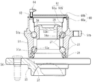
- FIG. 1 is a longitudinal sectional view showing an embodiment of a wheel bearing device with a rotational speed detection device according to the present invention
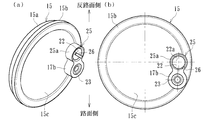
- FIG. 2 (a) is a perspective view showing a single cover of FIG. 1
- FIG. FIG. 3 is a front view of a
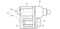
- FIG. 3 is a sectional view taken along IIIa-IIIb-IIIc-IIId in FIG. 2 (b)
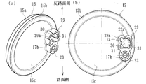
- FIG. 4 (a) is a perspective view showing a cover alone as a modification of FIG. (B) is a front view of (a)
- FIG. 5 (a) is another modification of FIG. 2, and is a perspective view showing a single cover
- (b) is a front view of (a)
- FIG. 2 is a perspective view showing a single cover
- FIG. 2B is a front view of FIG. 2
- FIG. 7A is another modified example of FIG.
- FIG. 8B is a front view of FIG. 8A
- FIG. 8 is a front view of the cover alone as a modification of FIG. 7.
- the side closer to the outer side of the vehicle when assembled to the vehicle is referred to as the outer side (left side in FIG. 1)
- the side closer to the center is referred to as the inner side (right side in FIG. 1).
- the double row rolling bearing 2 includes an inner member 3, an outer member 4, and double row rolling elements (balls) 5, 5 accommodated between the members 3, 4 so as to be freely rollable.
- the inner member 3 indicates a hub wheel 1 and an inner ring 7 that is press-fitted and fixed to the hub wheel 1.
- the hub wheel 1 integrally has a wheel mounting flange 6 for attaching a wheel (not shown) to an end portion on the outer side, one (outer side) inner rolling surface 1a on the outer periphery, and this inner rolling.
- An axial small-diameter step portion 1b extending in the axial direction from the surface 1a is formed.
- hub bolts 6 a for fastening the wheels are planted at the circumferentially equidistant positions of the wheel mounting flanges 6.
- the inner ring 7 is formed with the other (inner side) inner rolling surface 7a on the outer periphery, and is press-fitted into the small-diameter step portion 1b of the hub ring 1 through a predetermined squeeze. Then, the end portion of the small-diameter step portion 1b is plastically deformed radially outward to form a caulking portion 1c, and the inner ring 7 is given a predetermined bearing preload to the hub wheel 1 by the caulking portion 1c. It is fixed in the axial direction in the state.
- the hub wheel 1 is made of medium and high carbon steel containing 0.40 to 0.80 wt% of carbon such as S53C, and includes an inner rolling surface 1a and an inner side of a wheel mounting flange 6 that becomes a seal land portion of a seal 9 to be described later. From the base 6b to the small-diameter step portion 1b, the surface hardness is set to a range of 58 to 64 HRC by induction hardening.
- the caulking portion 1c is an unquenched portion having a surface hardness of 25HRC or less after forging.
- the inner ring 7 is made of a high carbon chrome bearing steel such as SUJ2, and is hardened in the range of 58 to 64 HRC to the core portion by quenching.
- the rolling element 5 is made of a high carbon chrome bearing steel such as SUJ2, and is hardened in the range of 62 to 67 HRC up to the core portion by quenching.
- the outer member 4 integrally has a vehicle body mounting flange 4b to be fixed to a knuckle (not shown) constituting a suspension device on the outer periphery, and the inner side of the double row of the inner members 3 on the inner periphery.
- Double row outer rolling surfaces 4a, 4a facing the rolling surfaces 1a, 7a are integrally formed.
- This outer member 4 is made of medium and high carbon steel containing 0.40 to 0.80 wt% of carbon such as S53C, and at least the double row outer rolling surfaces 4a and 4a have a surface hardness of 58 to 64 HRC by induction hardening. Hardened to range.
- the double-row rolling elements 5 and 5 are accommodated between both rolling surfaces 4a, 1a and 4a and 7a, and these double-row rolling elements 5 and 5 are hold
- seals 9 and 10 are attached to the opening of the annular space formed between the outer member 4 and the inner member 3, and leakage of the lubricating grease sealed inside the bearing to the outside and from the outside Rain water and dust are prevented from entering the bearing.
- the cover 11 is attached to the opening end on the inner side of the outer member 4, the opening on the inner side of the outer member 4 is blocked, and rainwater, dust and the like are prevented from entering the detection unit from the outside. ing.
- the seal 10 Since the opening on the inner side of the outer member 4 is closed by the cover 11, the seal 10 is basically unnecessary, but here, the seal 10 is provided at the inner end of the outer member 4. Therefore, the seal 10 can seal off the leakage of the grease sealed in the bearing. That is, since the enclosed grease does not flow out into the cover 11, the amount of grease can be minimized, the weight can be reduced, the cost can be reduced, and the grease can be stirred during operation. The temperature rise of the bearing can be suppressed.
- the double row rolling bearing 2 is exemplified by a double row angular contact ball bearing in which the rolling elements 5 and 5 are balls.
- the present invention is not limited thereto, and a tapered roller is used for the rolling element.
- the double-row tapered roller bearing may be configured.
- the third generation structure is illustrated, the present invention is not limited to this, and although not shown, a so-called second generation structure in which a pair of inner rings are press-fitted into the hub ring in a small diameter step portion of the hub ring may be used.
- the pulsar ring 12 is press-fitted into the outer diameter of the inner ring 7.
- the pulsar ring 12 includes a support ring 13 formed in an annular shape, and a magnetic encoder 14 that is integrally joined to a side surface of the support ring 13 by vulcanization adhesion or the like.
- This magnetic encoder 14 is a rotary encoder for detecting the rotational speed of a wheel by mixing magnetic powder such as ferrite in an elastomer such as rubber and magnetizing the magnetic poles N and S alternately in the circumferential direction. Yes.
- the support ring 13 is made of a ferromagnetic steel plate, for example, a ferritic stainless steel plate (JIS standard SUS430 or the like) or a rust-proof cold rolled steel plate (JIS standard SPCC or the like) by press working. It has a cylindrical fitting portion 13a that is L-shaped and is press-fitted into the inner ring 7, and a standing plate portion 13b that extends radially inward from the fitting portion 13a.
- the magnetic encoder 14 is joined to the inner side surface of the upright plate portion 13b.
- the cover 11 is fitted and fixed to the opening end of the outer member 4 on the inner side, and the opening of the outer member 4 is closed.
- the cover 11 includes a bottomed cylindrical cover body 15 made of synthetic resin and a cored bar 16 integrally molded in the opening of the cover body 15.
- the synthetic resin cover 15 may be directly attached to the outer member 4, by exposing the cored bar 16 to the fitting portion, the strength and rigidity of the cover 11 are increased and the pulling resistance is increased. The airtightness of the fitting part is improved.
- the cover body 15 is formed by injection molding from a non-magnetic special ether-based synthetic resin material such as polyphenylene sulfide (PPS), and further a reinforcing material such as GF (glass fiber) is added in an amount of 30 to 50 wt%.
- a non-magnetic special ether-based synthetic resin material such as polyphenylene sulfide (PPS)
- PPS polyphenylene sulfide
- GF glass fiber
- the cover main body 15 can be exemplified by injection-moldable synthetic resins such as PA (polyamide) 66, PA6.12, PPA (polyphthalamide), PBT (polybutylene terephthalate), etc., in addition to the materials described above.
- PA polyamide
- PA6.12 polyamide
- PPA polyphthalamide
- PBT polybutylene terephthalate
- fibrous reinforcement not only GF but CF (carbon fiber), an aramid fiber, a boron fiber, etc. can be illustrated other than this.
- the cored bar 16 is formed in an annular shape having an L-shaped cross section by press forming, for example, a stainless steel plate or a cold rolled steel plate.
- the metal core 16 is preferably formed of a non-magnetic steel plate, for example, an austenitic stainless steel plate (JIS standard SUS304, etc.) so as not to adversely affect the sensing performance of the rotational speed sensor 19. .
- the cover main body 15 includes a cylindrical fitting portion 15a fitted to the inner periphery of the end portion of the outer member (not shown), and this fitting.
- a flange portion 15b and a bottom portion 15c that protrude radially outward from the portion 15a and are in close contact with the end face of the outer member are provided.
- the attaching part 17 which protrudes in an axial direction is integrally formed in the radial direction outer part of this bottom part 15c.
- the mounting portion 17 includes a cylindrical insertion portion 17a to which a sensor unit (not shown) is mounted, and a cylindrical fixing portion 17b that is fixed by a fixing bolt via a mounting member to be described later. Is not disposed radially through the center of the bottom portion 15c of the cover main body 15, but the insertion portion 17a is disposed in a horizontal position passing through the center of the bottom portion 15c of the cover main body 15, and a fixed portion is provided vertically below the insertion portion 17a. 17b is disposed. As a result, as shown in FIG. 1, the degree of freedom in design for avoiding the attachment portion 17 from interfering with the site of the inner member 3 such as the caulking portion 1 c is increased, and the weight and size can be reduced. . An insertion hole 22 into which the sensor unit is mounted is formed in the insertion portion 17a, and a nut 23 to which the fixing bolt 21 is fastened is integrally embedded in the fixing portion 17b.
- the sensor unit 18 includes a rotation speed sensor 19 including a magnetic detection element that changes characteristics according to the flow direction of magnetic flux, such as a Hall element, a magnetoresistive element (MR element), and the like. It comprises an IC or the like in which a waveform shaping circuit (not shown) for adjusting the output waveform is incorporated, and constitutes an automobile ABS that detects the rotational speed of the wheel and controls its rotational speed. And it is being fixed to the attachment part 17 with the fixing bolt 21 through the eyebrow-type attachment member 20. As shown in FIG.
- the rotational speed sensor 19 can be prevented from shifting in the rotational direction with the fixing bolt 21 as a fulcrum, and the rotational speed sensor 19 is prevented from being eccentric with respect to the insertion hole 22. can do.
- the insertion hole 22 is formed at a position corresponding to the magnetic encoder 14, and is formed as a non-through hole having a bottom 22a.
- the wall thickness t of the bottom 22a is set in the range of 0.1 to 1.0 mm. If the thickness t is less than 0.1 mm, the strength and rigidity are insufficient, and there is a risk of deformation or breakage due to collision with other parts during assembly. If the thickness t exceeds 1.0 mm, the air gap Since it becomes too large and a necessary magnetic flux density cannot be obtained, it is not preferable.
- a slit 24 is formed in the insertion hole 22 in which a sensor unit (not shown) is mounted.
- a slit (discharge portion) 24 extending in the axial direction is formed in a part (here, one location) on the road surface side connected from the insertion portion 17 a to the fixing portion 17 b, and the insertion hole 22 is interposed through the slit 24. Open to the outside.
- foreign matter that has entered from the clearance between the sensor unit and the insertion hole 22 can be easily discharged without being against gravity, so that the sealing performance of the detection unit can be improved and the rotational speed sensor can be damaged by foreign matter. It is possible to provide a wheel bearing device with a rotational speed detection device that is prevented and improved in reliability.
- the active type rotational speed detection device including the magnetic encoder 14 shown in FIG. 1 and the rotational speed sensor 19 including a magnetic detection element such as a Hall element is illustrated, but the rotational speed detection device according to the present invention is illustrated.
- the present invention is not limited to this, and for example, a passive type composed of a magnetic encoder, a magnet and an annular coil wound around the magnet may be used.
- the mounting portion 25 shown in FIG. 4 is basically different in configuration from the insertion portion 17a of the above-described embodiment (FIG. 2). That is, the attachment portion 25 is configured by a cylindrical insertion portion 25a to which a sensor unit (not shown) is attached and a fixing portion 17b.
- the insertion portion 25a is at a horizontal position passing through the center of the bottom portion 15c of the cover body 15.
- the fixing portion 17b is disposed below the insertion portion 25a in the vertical direction.
- An insertion hole 22 is formed in the insertion portion 25a, and a discharge groove 26 is formed in the insertion hole 22.
- a discharge groove (discharge portion) 26 extending in the axial direction is formed in a part on the road surface side connected from the insertion portion 25a to the fixing portion 17b, and the insertion hole 22 is communicated to the outside through the discharge groove 26. ing.
- the discharge groove 26 of the insertion hole 22 is formed on a part of the right side in the figure on the road surface side connecting the insertion part 25a to the fixing part 17b. It is preferable to form the discharge groove 26 in the bottom.
- the normal fixing bolt is composed of a right-hand thread, and therefore the sensor unit slightly moves clockwise (in the fixing bolt tightening direction) at the time of fastening. Due to this movement, the radial clearance between the sensor unit and the insertion hole 22 at the time of attachment differs between the left and right sides of the insertion hole 22, and as a result, the clearance on the right side in the figure becomes smaller than the left side. Accordingly, foreign matter can be prevented from entering the insertion hole 22 and the foreign matter once entered can be easily discharged from the discharge groove 26 formed on the left side of the insertion hole 22 having a large clearance.
- the attachment portion 27 is configured by a cylindrical insertion portion 27a to which a sensor unit (not shown) is attached and a fixing portion 17b, and is disposed at a horizontal position passing through the center of the bottom portion 15c of the cover body 15. Yes.
- An insertion hole 22 is formed in the insertion portion 27a, and a slit 28 is formed in the insertion hole 22.
- a slit 28 extending in the axial direction is formed at a portion closest to the road surface of the insertion portion 27a, and the insertion hole 22 is opened to the outside through the slit 28.
- the attachment portion 29 shown in FIG. 6 is basically different in shape from the insertion portion 17a of the above-described embodiment (FIG. 2). That is, the attachment portion 29 includes a cylindrical insertion portion 29a to which a sensor unit (not shown) is attached and a fixing portion 17b.
- the insertion portion 29a is in a horizontal position passing through the center of the bottom portion 15c of the cover body 15.
- the fixing portion 17b is disposed below the insertion portion 29a in the vertical direction.
- An insertion hole 30 is formed in the insertion portion 29a, and a plurality of (in this case, four) discharge grooves 31 extending in the axial direction are formed on the inner periphery of the insertion hole 30 at equal intervals in the circumferential direction.
- the discharge groove 31 is formed in a tapered shape that gradually becomes wider toward the opening, and the insertion hole 30 communicates with the outside through the discharge groove 31. Thereby, the foreign material which penetrate
- the attachment portion 32 includes a cylindrical insertion portion 32a to which the sensor unit 18 is mounted and a fixing portion 17b.
- the insertion portion 32a is disposed at a horizontal position passing through the center of the bottom portion 15c of the cover body 15.
- a fixing portion 17b is disposed below the insertion portion 32a in the vertical direction.
- the insertion portion 32a is formed in a rectangular cross section (here, triangular), and an insertion hole 33 having a rectangular cross section (here, triangular) corresponding to the outer peripheral shape is formed therein.
- the corner of the insertion hole 33 is formed in an arcuate surface, and as shown in (b), a space (gap) with the inserted sensor unit 18 constitutes a discharge groove 34 extending in the axial direction. Therefore, the insertion hole 33 communicates with the outside through the discharge groove 34, and foreign matter that has entered from the space (gap) between the sensor unit 18 and the insertion hole 33 can be easily discharged.
- the attachment portion 35 includes a cylindrical insertion portion 35a to which the sensor unit 18 is mounted and a fixing portion 17b.
- the insertion portion 35a is disposed at a horizontal position passing through the center of the bottom portion 15c of the cover body 15, A fixing portion 17b is disposed below the insertion portion 35a in the vertical direction.
- the insertion portion 35a is formed in a triangular cross section, and an insertion hole 36 having a triangular cross section is formed therein.
- the corner on the side opposite to the road surface is formed into an arcuate surface having a larger radius of curvature than the other corners (here, the same radius of curvature as the radius of curvature of the sensor unit 18).
- a discharge groove 34 is formed which is in close contact with the inserted sensor unit 18 and in which a space (gap) between the other corners on the road surface side and the sensor unit 18 extends in the axial direction.
- the insertion hole 36 communicates with the outside through the discharge groove 34, and foreign matter that has entered from the space (gap) between the sensor unit 18 and the insertion hole 36 can be easily discharged, and the sensor unit 18 can be loosened. Positioning can be performed without any problem, and detection accuracy can be improved.
- the wheel bearing device with a rotation speed detection device according to the present invention can be applied to a second-generation or third-generation wheel bearing device of an inner ring rotation type.
Landscapes
- Engineering & Computer Science (AREA)
- General Engineering & Computer Science (AREA)
- Mechanical Engineering (AREA)
- Physics & Mathematics (AREA)
- General Physics & Mathematics (AREA)
- Rolling Contact Bearings (AREA)
Abstract
検出部の密封性を向上させると共に、センサの信頼性の向上を図った回転速度検出装置付き車輪用軸受装置を提供する。 カバー本体15の取付部17が、底部を有する非貫通の挿入孔22が形成された挿入部17aと、取付部材を介して固定ボルトによって回転速度センサが固定される円筒状の固定部17bで構成され、挿入部17aが、カバー本体15の底部15cの中心を通る水平位置に配設され、この挿入部17aの鉛直方向下方に固定部17bが配設されと共に、挿入孔22の底部22aを介して回転速度センサとパルサリングが対峙され、挿入孔22の路面側に軸方向に延びるスリットまたは排出溝からなる排出部24が形成されて挿入孔22が外部に連通されている。
Description
本発明は、自動車等の車輪を懸架装置に対して回転自在に支承する車輪用軸受装置、特に、車輪の回転速度を検出する回転速度検出装置が内蔵され、検出部の密封性の向上を図ると共に、信頼性の向上を図った回転速度検出装置付き車輪用軸受装置に関するものである。
周方向に磁気特性が変化するエンコーダと、このエンコーダの回転に伴い、車輪の回転速度を検出して車両のアンチロックブレーキシステム(ABS)を制御する回転速度センサとからなる回転速度検出装置は、エンコーダとのエアギャップの調整作業の煩雑さを解消すると共に、よりコンパクト化を狙って、最近では回転速度センサが軸受に内蔵されたものが提案されている。
このような回転速度検出装置付き車輪用軸受装置の一例として図9に示すような構造が知られている。この回転速度検出装置付き車輪用軸受装置は、図示しないナックルに支持固定され、固定部材となる外方部材51と、この外方部材51に複列のボール53、53を介して内挿された内方部材52とを有している。内方部材52は、ハブ輪55と、このハブ輪55に外嵌された内輪56とからなる。
外方部材51は、外周にナックルに取り付けられるための車体取付フランジ51bを一体に有し、内周には複列の外側転走面51a、51aが形成されている。一方、内方部材52は、前記した外方部材51の外側転走面51a、51aに対向する複列の内側転走面55a、56aが形成されている。これら複列の内側転走面55a、56aのうち一方の内側転走面55aはハブ輪55の外周に一体形成され、他方の内側転走面56aは内輪56の外周に形成されている。この内輪56は、ハブ輪55の内側転走面55aから軸方向に延びる軸状の小径段部55bに圧入されている。そして、複列のボール53、53がこれら両転走面間にそれぞれ収容され、保持器57、57によって転動自在に保持されている。
ハブ輪55は、外周に車輪(図示せず)を取り付けるための車輪取付フランジ54を一体に有し、小径段部55bの端部を径方向外方に塑性変形して加締部58が形成され、この加締部58によって前記内輪56が軸方向に固定されている。そして、外方部材51の端部にはシール59およびカバー60が装着され、軸受内部に封入された潤滑グリースの漏洩と、外部から軸受内部に雨水やダスト等が侵入するのを防止している。
内輪56の外径にはエンコーダ61が圧入されている。このエンコーダ61は、軟鋼板等の磁性金属板に塑性加工を施すことにより全体が円環状に形成され、内輪56の外径に圧入される円筒状の取付部61aと、この取付部61aの一端の鍔部に取り付けられたエンコーダ本体61bとからなる。このエンコーダ本体61bは、例えば、ゴム磁石等の永久磁石を環状に形成して、周方向に交互に磁極N、Sが現われるように着磁され、周方向の回転によって磁界変動が生じるようになっている。
カバー60は、合成樹脂を射出成形してなる有底円筒状に形成され、外方部材51の内方側の開口端部に筒部60aが内嵌固定され、蓋部60bで外方部材51の開口部を閉塞している。このカバー60は、図10に示すように、蓋部60bに筒状のセンサ取付部62が設けられ、その内周側に形成されたセンサ取付穴63にセンサ64の挿入部64aが挿入されている。センサ取付穴63の奥側には、このセンサ取付穴63と装置内部空間65とを仕切る0.3~0.5mmの厚さの仕切壁66が設けられている。この仕切壁66はカバー60と一体に射出成形され、その素材の合成樹脂が非磁性であるため、回転速度の検出精度には影響を及ぼさない。
センサ64は、外装部分が合成樹脂製で、センサ挿入部64aをカバー60のセンサ取付穴63に挿入することによりカバー60に取り付けられている。そのセンサ挿入部64aは、センサ取付穴63の奥側の仕切壁66を挟んでエンコーダ本体61bの一部と所定の間隔をおいて対向し、エンコーダ本体61bとの対向面の近傍に、エンコーダ61の回転によって発生する磁界変動を検出する検出部(図示せず)が内蔵されている。
このような従来の回転速度検出装置付き車輪用軸受装置によれば、カバー60のセンサ取付穴63に奥側に、センサ取付穴63と装置内部空間65とを仕切る仕切壁66が設けられているので、従来の装置に比べ、センサ取付穴63がカバー60を貫通していない分、装置内部への異物の侵入経路が少なく、装置全体のシール性が優れている。また、仕切壁66がカバー60と一体成形されているため、構造が簡単で組立の手間が少なくて済む(例えば、特許文献1参照。)。
このような従来の回転速度検出装置付き車輪用軸受装置では、カバー60のセンサ取付穴63に奥側に、センサ取付穴63と装置内部空間65とを仕切る仕切壁66が設けられているので、装置内部への異物の侵入経路が少なく、装置全体のシール性が優れているという特徴を備えている。然しながら、通常、エンコーダ61とセンサ64とのエアギャップは小さい方が検出精度が向上し、2mmを超えると著しく検出精度が低下することが知られているため、仕切壁66の厚さを薄く設定する必要があるが、検出部に異物を噛み込むとこの仕切壁66が損傷し、密封性が損なわれる恐れがある。
また、センサ取付穴63がカバー60を貫通していない分、装置内部への異物の侵入経路が少ない反面、一旦センサ取付穴63内に入った異物が排出され難いと言った問題があった。
本発明は、このような従来の問題に鑑みてなされたもので、検出部の密封性を向上させると共に、センサの信頼性の向上を図った回転速度検出装置付き車輪用軸受装置を提供することを目的とする。
係る目的を達成すべく、本発明のうち請求項1に記載の発明は、外周にナックルに取り付けられるための車体取付フランジを一体に有し、内周に複列の外側転走面が一体に形成された外方部材と、一端部に車輪を取り付けるための車輪取付フランジを一体に有し、外周に軸方向に延びる小径段部が形成されたハブ輪、およびこのハブ輪の小径段部に圧入された少なくとも一つの内輪からなり、外周に前記複列の外側転走面に対向する複列の内側転走面が形成された内方部材と、この内方部材と前記外方部材の両転走面間に転動自在に収容された複列の転動体と、前記内輪に外嵌され、周方向に磁気特性が交互に、かつ等間隔に変化するパルサリングと、前記外方部材のインナー側の端部に装着され、当該外方部材のインナー側の開口部を閉塞する合成樹脂製の有底円筒状のカバーと、このカバーの径方向外方部に軸方向に突出して形成された円筒状の取付部に装着され、前記パルサリングと所定のエアギャップを介して対峙された回転速度センサとを備えた回転速度検出装置付き車輪用軸受装置において、前記カバーの取付部が、底部を有する非貫通の挿入孔が形成された挿入部と、取付部材を介して固定ボルトによって前記回転速度センサが固定される円筒状の固定部で構成され、前記挿入孔の底部を介して前記回転速度センサとパルサリングが対峙されると共に、前記挿入孔の路面側に軸方向に延びるスリットまたは排出溝からなる排出部が形成され、前記挿入孔が外部に連通されている。
このように、内輪に外嵌され、周方向に磁気特性が交互に、かつ等間隔に変化するパルサリングと、外方部材のインナー側の端部に装着され、当該外方部材のインナー側の開口部を閉塞する合成樹脂製の有底円筒状のカバーと、このカバーの径方向外方部に軸方向に突出して形成された円筒状の取付部に装着され、パルサリングと所定のエアギャップを介して対峙された回転速度センサとを備えた回転速度検出装置付き車輪用軸受装置において、カバーの取付部が、底部を有する非貫通の挿入孔が形成された挿入部と、取付部材を介して固定ボルトによって回転速度センサが固定される円筒状の固定部で構成され、挿入孔の底部を介して回転速度センサとパルサリングが対峙されると共に、挿入孔の路面側に軸方向に延びるスリットまたは排出溝からなる排出部が形成され、挿入孔が外部に連通されているので、センサユニットと挿入孔とのすきまから侵入した異物を重力に逆らわず容易に排出させることができ、検出部の密封性を向上させると共に、異物によって回転速度センサが傷付くのを防止して信頼性の向上を図った回転速度検出装置付き車輪用軸受装置を提供することができる。
好ましくは、請求項2に記載の発明のように、前記取付部の挿入部が、前記カバーの底部の中心を通る水平位置に配設され、この挿入部の鉛直方向下方に前記固定部が配設されと共に、前記排出部が前記挿入部から固定部に繋がる路面側の一部に形成されていれば、内方部材との干渉を回避することができ、装置の軽量・コンパクト化を図ることができる。
また、請求項3に記載の発明のように、前記挿入孔の排出部が前記固定ボルトの反締付方向に形成されていれば、締結時にセンサが固定ボルトの締付方向に僅かに動き、取付時のセンサと挿入孔との径方向すきまが締付方向側が反締付方向側より小さくなり、挿入孔内に異物が侵入するのを抑制すると共に、一旦入った異物が、すきまの大きな挿入孔の反締付側に形成された排出部から容易に排出させることができる。
また、請求項4に記載の発明のように、前記取付部の挿入部と固定部が前記カバーの底部の中心を通る水平位置にそれぞれ配設され、前記排出部が前記挿入部の路面に最も近い部位に形成されていれば、センサと挿入孔とのすきまから侵入した異物を効果的に排出させることができる。
また、請求項5に記載の発明のように、前記挿入孔の内周に軸方向に延びる複数の排出溝が形成され、この排出溝が開口部に向って漸次幅広となるテーパ状に形成されて前記排出部を構成していれば、センサと挿入孔とのすきまから侵入した異物を容易に排出させることができる。
また、請求項6に記載の発明のように、前記挿入孔が断面矩形状に形成され、この挿入孔の角部が円弧面に形成されていれば、挿入されたセンサとの空間(すきま)が軸方向に延びる排出溝を構成し、センサと挿入孔とのすきまから侵入した異物を容易に排出させることができる。
また、請求項7に記載の発明のように、前記挿入孔が断面三角形状に形成され、この挿入孔の角部のうち反路面側の角部が他の角部に比べ大きな曲率半径からなる円弧面に形成されていれば、挿入されたセンサと密着すると共に、路面側の他の角部とセンサとのすきまが軸方向に延びる排出溝を構成し、センサと挿入孔との空間(すきま)から侵入した異物を容易に排出させることができると共に、センサをガタなく位置決めすることができ、検出精度を向上させることができる。
本発明に係る回転速度検出装置付き車輪用軸受装置は、外周にナックルに取り付けられるための車体取付フランジを一体に有し、内周に複列の外側転走面が一体に形成された外方部材と、一端部に車輪を取り付けるための車輪取付フランジを一体に有し、外周に軸方向に延びる小径段部が形成されたハブ輪、およびこのハブ輪の小径段部に圧入された少なくとも一つの内輪からなり、外周に前記複列の外側転走面に対向する複列の内側転走面が形成された内方部材と、この内方部材と前記外方部材の両転走面間に転動自在に収容された複列の転動体と、前記内輪に外嵌され、周方向に磁気特性が交互に、かつ等間隔に変化するパルサリングと、前記外方部材のインナー側の端部に装着され、当該外方部材のインナー側の開口部を閉塞する合成樹脂製の有底円筒状のカバーと、このカバーの径方向外方部に軸方向に突出して形成された円筒状の取付部に装着され、前記パルサリングと所定のエアギャップを介して対峙された回転速度センサとを備えた回転速度検出装置付き車輪用軸受装置において、前記カバーの取付部が、底部を有する非貫通の挿入孔が形成された挿入部と、取付部材を介して固定ボルトによって前記回転速度センサが固定される円筒状の固定部で構成され、前記挿入孔の底部を介して前記回転速度センサとパルサリングが対峙されると共に、前記挿入孔の路面側に軸方向に延びるスリットまたは排出溝からなる排出部が形成され、前記挿入孔が外部に連通されているので、センサユニットと挿入孔とのすきまから侵入した異物を重力に逆らわず容易に排出させることができ、検出部の密封性を向上させると共に、異物によって回転速度センサが傷付くのを防止して信頼性の向上を図った回転速度検出装置付き車輪用軸受装置を提供することができる。
外周にナックルに取り付けられるための車体取付フランジを一体に有し、内周に複列の外側転走面が一体に形成された外方部材と、一端部に車輪を取り付けるための車輪取付フランジを一体に有し、外周に前記複列の外側転走面の一方に対向する内側転走面と、この内側転走面から軸方向に延びる小径段部が形成されたハブ輪、およびこのハブ輪の小径段部に圧入され、外周に前記複列の外側転走面の他方に対向する内側転走面が形成された内輪からなる内方部材と、この内方部材と前記外方部材のそれぞれの転走面間に転動自在に収容された複列の転動体と、前記内輪に外嵌され、周方向に磁気特性が交互に、かつ等間隔に変化するパルサリングと、前記外方部材のインナー側の端部に装着され、当該外方部材のインナー側の開口部を閉塞する合成樹脂製の有底円筒状のカバーとを備え、このカバーの径方向外方部に軸方向に突出して形成された円筒状の取付部に回転速度センサ装着され、前記パルサリングと所定のエアギャップを介して対峙された回転速度検出装置付き車輪用軸受装置において、前記カバーの取付部が、底部を有する非貫通の挿入孔が形成された挿入部と、取付部材を介して固定ボルトによって前記回転速度センサが固定される円筒状の固定部で構成され、前記挿入部が、前記カバーの底部の中心を通る水平位置に配設され、この挿入部の鉛直方向下方に前記固定部が配設されと共に、前記挿入孔の底部を介して前記回転速度センサとパルサリングが対峙され、前記挿入孔の路面側に軸方向に延びるスリットまたは排出溝からなる排出部が形成されて前記挿入孔が外部に連通されている。
以下、本発明の実施の形態を図面に基づいて詳細に説明する。
図1は、本発明に係る回転速度検出装置付き車輪用軸受装置の一実施形態を示す縦断面図、図2(a)は、図1のカバー単体を示す斜視図、(b)は、(a)の正面図、図3は、図2(b)のIIIa-IIIb-IIIc-IIIdに沿った断面図、図4(a)は、図2の変形例で、カバー単体を示す斜視図、(b)は、(a)の正面図、図5(a)は、図2の他の変形例で、カバー単体を示す斜視図、(b)は、(a)の正面図、図6(a)は、図2の他の変形例で、カバー単体を示す斜視図、(b)は、(a)の正面図、図7(a)は、図2の他の変形例で、カバー単体を示す斜視図、(b)は、(a)の正面図、図8は、図7の変形例で、カバー単体を示す正面図である。なお、以下の説明では、車両に組み付けた状態で車両の外側寄りとなる側をアウター側(図1の左側)、中央寄り側をインナー側(図1の右側)という。
図1は、本発明に係る回転速度検出装置付き車輪用軸受装置の一実施形態を示す縦断面図、図2(a)は、図1のカバー単体を示す斜視図、(b)は、(a)の正面図、図3は、図2(b)のIIIa-IIIb-IIIc-IIIdに沿った断面図、図4(a)は、図2の変形例で、カバー単体を示す斜視図、(b)は、(a)の正面図、図5(a)は、図2の他の変形例で、カバー単体を示す斜視図、(b)は、(a)の正面図、図6(a)は、図2の他の変形例で、カバー単体を示す斜視図、(b)は、(a)の正面図、図7(a)は、図2の他の変形例で、カバー単体を示す斜視図、(b)は、(a)の正面図、図8は、図7の変形例で、カバー単体を示す正面図である。なお、以下の説明では、車両に組み付けた状態で車両の外側寄りとなる側をアウター側(図1の左側)、中央寄り側をインナー側(図1の右側)という。
図1に示す回転速度検出装置付き車輪用軸受装置は従動輪側の第3世代と呼称され、ハブ輪1と複列の転がり軸受2とがユニット化して構成されている。複列の転がり軸受2は、内方部材3と外方部材4、および両部材3、4間に転動自在に収容された複列の転動体(ボール)5、5とを備えている。内方部材3は、ハブ輪1と、このハブ輪1に圧入固定された内輪7とを指す。
ハブ輪1は、アウター側の端部に車輪(図示せず)を取り付けるための車輪取付フランジ6を一体に有し、外周に一方(アウター側)の内側転走面1aと、この内側転走面1aから軸方向に延びる軸状の小径段部1bが形成されている。また、車輪取付フランジ6の円周等配位置には車輪を締結するハブボルト6aが植設されている。
内輪7は、外周に他方(インナー側)の内側転走面7aが形成され、ハブ輪1の小径段部1bに所定のシメシロを介して圧入されている。そして、小径段部1bの端部を径方向外方に塑性変形させて加締部1cが形成され、この加締部1cによってハブ輪1に対して内輪7が所定の軸受予圧が付与された状態で軸方向に固定されている。
ハブ輪1はS53C等の炭素0.40~0.80wt%を含む中高炭素鋼で形成され、内側転走面1aをはじめ、後述するシール9のシールランド部となる車輪取付フランジ6のインナー側の基部6bから小径段部1bに亙って高周波焼入れによって表面硬さを58~64HRCの範囲に硬化処理されている。なお、加締部1cは、鍛造後の素材表面硬さ25HRC以下の未焼入れ部とされている。また、内輪7はSUJ2等の高炭素クロム軸受鋼からなり、ズブ焼入れにより芯部まで58~64HRCの範囲で硬化処理されている。また、転動体5は、SUJ2等の高炭素クロム軸受鋼からなり、ズブ焼入れにより芯部まで62~67HRCの範囲で硬化処理されている。
一方、外方部材4は、外周に懸架装置を構成するナックル(図示せず)に固定されるための車体取付フランジ4bを一体に有し、内周に前記内方部材3の複列の内側転走面1a、7aに対向する複列の外側転走面4a、4aが一体に形成されている。この外方部材4はS53C等の炭素0.40~0.80wt%を含む中高炭素鋼で形成され、少なくとも複列の外側転走面4a、4aが高周波焼入れによって表面硬さを58~64HRCの範囲に硬化処理されている。そして、両転走面4a、1aおよび4a、7a間に複列の転動体5、5収容され、これら複列の転動体5、5が保持器8、8によって転動自在に保持されている。
また、外方部材4と内方部材3との間に形成される環状空間の開口部にはシール9、10が装着され、軸受内部に封入された潤滑グリースの外部への漏洩と、外部から雨水やダスト等が軸受内部に侵入するのを防止している。さらに、外方部材4のインナー側の開口端部にカバー11が装着され、外方部材4のインナー側の開口部が閉塞され、外部から雨水やダスト等が検出部に侵入するのを防止している。
なお、外方部材4のインナー側の開口部がカバー11により閉塞されているため、基本的にはシール10は不要であるが、ここでは、外方部材4のインナー側の端部にシール10が装着されているので、軸受内部に封入されたグリースが漏洩するのをこのシール10で密封することができる。すなわち、封入されたグリースはカバー11内に流出することがないので、グリース封入量を最小限に抑えることができ、軽量化と低コスト化を図ることができると共に、運転中のグリースの撹拌による軸受の昇温を抑えることができる。
なお、本実施形態では、複列の転がり軸受2として、転動体5、5をボールとした複列アンギュラ玉軸受で構成されたものを例示したが、これに限らず転動体に円錐ころを使用した複列円錐ころ軸受で構成されていても良い。また、第3世代の構造を例示したが、これに限らず、図示はしないが、ハブ輪の小径段部に一対の内輪をハブ輪に圧入した、所謂第2世代構造であっても良い。
本実施形態では、内輪7の外径にパルサリング12が圧入されている。このパルサリング12は、円環状に形成された支持環13と、この支持環13の側面に加硫接着等で一体に接合された磁気エンコーダ14とで構成されている。この磁気エンコーダ14は、ゴム等のエラストマにフェライト等の磁性体粉が混入され、周方向等配で交互に磁極N、Sが着磁されて車輪の回転速度検出用のロータリエンコーダを構成している。
支持環13は、強磁性体の鋼板、例えば、フェライト系のステンレス鋼板(JIS規格のSUS430系等)や防錆処理された冷間圧延鋼板(JIS規格のSPCC系等)からプレス加工によって断面略L字状に形成され、内輪7に圧入される円筒状の嵌合部13aと、この嵌合部13aから径方向内方に延びる立板部13bとを有している。この立板部13bのインナー側の側面に磁気エンコーダ14が接合されている。
カバー11は外方部材4のインナー側の開口端部に内嵌固定され、外方部材4の開口部が閉塞されている。このカバー11は、合成樹脂製の有底円筒状のカバー本体15と、このカバー本体15の開口部に一体モールドされた芯金16とからなる。なお、合成樹脂製のカバー15を直接外方部材4に装着するようにしても良いが、芯金16を嵌合部に露出させることによりカバー11の強度・剛性が増して抜け耐力が高まると共に、嵌合部の気密性が向上する。
カバー本体15は、ポリフェニレンサルファイド(PPS)等の非磁性の特殊エーテル系合成樹脂材から射出成形によって形成され、さらにGF(ガラスファイバー)等の強化材が30~50wt%添加されている。これにより、後述する回転速度センサ19の感知性能に悪影響を及ぼさず、また、耐食性に優れ、強度・剛性が高くなり長期間に亘って耐久性を向上させることができる。なお、カバー本体15は前述した材質以外にPA(ポリアミド)66、PA6・12、PPA(ポリフタルアミド)、PBT(ポリブチレンテレフタレート)等の射出成形可能な合成樹脂を例示することができる。また、繊維状強化材としては、GFに限らず、これ以外に、CF(炭素繊維)やアラミド繊維、ホウ素繊維等を例示することができる。
また、芯金16は、例えば、ステンレス鋼板や冷間圧延鋼板等をプレス成形して断面L字形の円環状に形成されている。特に、この芯金16は、回転速度センサ19の感知性能に悪影響を及ぼさないように、非磁性体の鋼板、例えば、オーステナイト系ステンレス鋼板(JIS規格のSUS304系等)で形成されるのが好ましい。
また、図2(a)、(b)に示すように、カバー本体15は、外方部材(図示せず)の端部内周に嵌合される円筒状の嵌合部15aと、この嵌合部15aから径方向外方に突出し、外方部材の端面に密着する鍔部15bおよび底部15cを備えている。そして、この底部15cの径方向外方部に軸方向に突出する取付部17が一体に形成されている。
取付部17は、センサユニット(図示せず)が装着される円筒状の挿入部17aと、後述する取付部材を介して固定ボルトによって固定される円筒状の固定部17bで構成され、取付部17をカバー本体15の底部15cの中心を通る放射状に配置せずに、挿入部17aはカバー本体15の底部15cの中心を通る水平位置に配設され、この挿入部17aの鉛直方向下方に固定部17bが配設されている。これにより、図1にあるように、取付部17が加締部1c等の内方部材3の部位に干渉するのを回避する設計の自由度が高くなり、軽量・コンパクト化を図ることができる。また、挿入部17aにはセンサユニットが装着される挿入孔22が形成されると共に、固定部17bには固定ボルト21が締結されるナット23が一体に埋設されている。
センサユニット18は、図3に示すように、ホール素子、磁気抵抗素子(MR素子)等、磁束の流れ方向に応じて特性を変化させる磁気検出素子からなる回転速度センサ19およびこの磁気検出素子の出力波形を整える図示しない波形整形回路が組み込まれたIC等からなり、車輪の回転速度を検出してその回転数を制御する自動車のABSを構成している。そして、まゆ型の取付部材20を介して固定ボルト21によって取付部17に固定されている。これにより、固定ボルト21の締結時に、回転速度センサ19が固定ボルト21を支点に回転方向にずれるのを防止することができ、挿入孔22に対して、回転速度センサ19が偏心するのを防止することができる。
本実施形態では、挿入孔22は磁気エンコーダ14に対応する位置に形成され、底部22aを有する非貫通孔に形成されている。この底部22aの肉厚tは0.1~1.0mmの範囲に設定されている。肉厚tが0.1mm未満では、強度・剛性が不足し、組立時に他の部品と衝突して変形や割損する恐れがあり、また、肉厚tが1.0mmを超えると、エアギャップが大きくなり過ぎて必要な磁束密度が得られないので好ましくない。
ここで、図2に戻って、本発明に係るカバー11の取付部17では、センサユニット(図示せず)が装着される挿入孔22にスリット24が形成されている。具体的には、挿入部17aから固定部17bに繋がる路面側の一部(ここでは、1箇所)に軸方向に延びるスリット(排出部)24が形成され、挿入孔22がこのスリット24を介して外部に開放されている。これにより、センサユニットと挿入孔22とのすきまから侵入した異物を重力に逆らわず容易に排出させることができるので、検出部の密封性を向上させると共に、異物によって回転速度センサが傷付くのを防止して信頼性の向上を図った回転速度検出装置付き車輪用軸受装置を提供することができる。
なお、ここでは、図1に示す磁気エンコーダ14と、ホール素子等の磁気検出素子からなる回転速度センサ19とからなるアクティブタイプの回転速度検出装置を例示したが、本発明に係る回転速度検出装置はこれに限らず、例えば、磁気エンコーダと、磁石と巻回された環状のコイル等からなるパッシブタイプであっても良い。
次に、図4乃至図8を用いて前述したカバー本体の取付部の変形例を説明する。なお、前述した実施形態と同一部品同一部位あるいは同様の機能を有する部品や部位には同じ符号を付して詳細な説明を省略する。
図4に示す取付部25は、基本的には前述した実施形態(図2)の挿入部17aと構成が異なる。すなわち、取付部25は、センサユニット(図示せず)が装着される円筒状の挿入部25aと固定部17bで構成され、挿入部25aは、カバー本体15の底部15cの中心を通る水平位置に配設され、この挿入部25aの鉛直方向下方に固定部17bが配設されている。
挿入部25aには挿入孔22が形成され、この挿入孔22に排出溝26が形成されている。具体的には、挿入部25aから固定部17bに繋がる路面側の一部に軸方向に延びる排出溝(排出部)26が形成され、この排出溝26を介して挿入孔22は外部に連通されている。これにより、前述した実施形態と同様、センサユニットと挿入孔22とのすきまから侵入した異物を重力に逆らわず容易に排出させることができるので、検出部の密封性を向上させると共に、異物によって回転速度センサが傷付くのを防止して信頼性を向上させることができる。
なお、ここでは、挿入孔22の排出溝26が挿入部25aから固定部17bに繋がる路面側の図中右の一部に形成されているが、固定ボルトが右ねじの場合は、図中左側に排出溝26を形成するのが好ましい。何故なら、通常固定ボルトは右ねじで構成されているため、締結時にセンサユニットが時計回り(固定ボルトの締付方向)に僅かに動いてしまう。この動きにより、取付時のセンサユニットと挿入孔22との径方向すきまが、挿入孔22の左右で異なることになり、その結果、図中右側の方のすきまが左側に比べて小さくなる。これにより、挿入孔22内に異物が侵入するのを抑制すると共に、一旦入った異物がすきまの大きな挿入孔22の左側に形成された排出溝26から容易に排出させることができる。
図5に示す取付部27は、基本的には前述した実施形態(図2)と挿入部17aと固定部17bの配置が異なる。すなわち、取付部27は、センサユニット(図示せず)が装着される円筒状の挿入部27aと固定部17bで構成され、カバー本体15の底部15cの中心を通る水平位置にそれぞれ配設されている。
挿入部27aには挿入孔22が形成され、この挿入孔22にスリット28が形成されている。具体的には、挿入部27aの路面に最も近い部位に軸方向に延びるスリット28が形成され、このスリット28を介して挿入孔22は外部に開放されている。これにより、センサユニットと挿入孔22とのすきまから侵入した異物を重力に逆らわずに効果的に排出させることができる。
図6に示す取付部29は、基本的には前述した実施形態(図2)の挿入部17aと形状が異なる。すなわち、取付部29は、センサユニット(図示せず)が装着される円筒状の挿入部29aと固定部17bで構成され、挿入部29aは、カバー本体15の底部15cの中心を通る水平位置に配設され、この挿入部29aの鉛直方向下方に固定部17bが配設されている。
挿入部29aには挿入孔30が形成され、この挿入孔30の内周に軸方向に延びる複数(ここでは、4箇所)の排出溝31が周方向等配に形成されている。この排出溝31は開口部に向って漸次幅広となるテーパ状に形成され、この排出溝31を介して挿入孔30は外部に連通されている。これにより、センサユニットと挿入孔30とのすきまから侵入した異物を容易に排出させることができる。
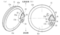
図7に示す取付部32は、基本的には前述した実施形態(図2)の挿入部17aと形状が異なる。すなわち、取付部32は、センサユニット18が装着される円筒状の挿入部32aと固定部17bで構成され、挿入部32aは、カバー本体15の底部15cの中心を通る水平位置に配設され、この挿入部32aの鉛直方向下方に固定部17bが配設されている。
挿入部32aは断面矩形状(ここでは、三角形状)に形成され、その内部に、外周形状に対応する断面矩形状(ここでは、三角形状)の挿入孔33が形成されている。挿入孔33の角部は円弧面に形成され、(b)に示すように、挿入されたセンサユニット18との空間(すきま)が軸方向に延びる排出溝34を構成している。したがって、この排出溝34を介して挿入孔33は外部に連通され、センサユニット18と挿入孔33との空間(すきま)から侵入した異物を容易に排出させることができる。
図8に示す取付部35は、基本的には前述した実施形態(図7)の挿入部32aと形状が異なる。すなわち、取付部35は、センサユニット18が装着される円筒状の挿入部35aと固定部17bで構成され、挿入部35aは、カバー本体15の底部15cの中心を通る水平位置に配設され、この挿入部35aの鉛直方向下方に固定部17bが配設されている。
挿入部35aは断面三角形状に形成され、その内部に断面三角形状の挿入孔36が形成されている。挿入孔36の角部のうち反路面側の角部は他の角部に比べ大きな曲率半径(ここでは、センサユニット18の曲率半径と同じ曲率半径)からなる円弧面に形成され、(b)に示すように、挿入されたセンサユニット18と密着すると共に、路面側の他の角部とセンサユニット18との空間(すきま)が軸方向に延びる排出溝34を構成している。したがって、この排出溝34を介して挿入孔36は外部に連通され、センサユニット18と挿入孔36との空間(すきま)から侵入した異物を容易に排出させることができると共に、センサユニット18をガタなく位置決めすることができ、検出精度を向上させることができる。
以上、本発明の実施の形態について説明を行ったが、本発明はこうした実施の形態に何等限定されるものではなく、あくまで例示であって、本発明の要旨を逸脱しない範囲内において、さらに種々なる形態で実施し得ることは勿論のことであり、本発明の範囲は、特許請求の範囲の記載によって示され、さらに特許請求の範囲に記載の均等の意味、および範囲内のすべての変更を含む。
本発明に係る回転速度検出装置付き車輪用軸受装置は、内輪回転タイプの第2世代または第3世代構造の車輪用軸受装置に適用することができる。
1 ハブ輪
1a、7a 内側転走面
1b 小径段部
1c 加締部
2 複列の転がり軸受
3 内方部材
4 外方部材
4a 外側転走面
4b 車体取付フランジ
5 転動体
6 車輪取付フランジ
6a ハブボルト
6b 基部
7 内輪
8 保持器
9、10 シール
11 カバー
12 パルサリング
13 支持環
13a 嵌合部
13b 立板部
14 磁気エンコーダ
15 カバー本体
15a 嵌合部
15b 鍔部
15c カバー本体の底部
16 芯金
17、25、27、29、32、35 取付部
17a、25a、27a、29a、32a、35a 挿入部
17b 固定部
18 センサユニット
19 回転速度センサ
20 取付部材
21 固定ボルト
22、30、33、36 挿入孔
22a 挿入孔の底部
23 ナット
24、28 スリット
26、31、34 排出溝
29a 挿入部
51 外方部材
51a 外側転走面
51b 車体取付フランジ
52 内方部材
53 ボール
54 車輪取付フランジ
55 ハブ輪
55a、56a 内側転走面
55b 小径段部
56 内輪
57 保持器
58 加締部
59 シール
60 カバー
60a 筒部
60b 蓋部
61 エンコーダ
61a 取付部
61b エンコーダ本体
62 センサ取付部
63 センサ取付穴
64 センサ
64a センサ挿入部
65 装置内部空間
66 仕切壁
t 挿入孔の底部の肉厚
1a、7a 内側転走面
1b 小径段部
1c 加締部
2 複列の転がり軸受
3 内方部材
4 外方部材
4a 外側転走面
4b 車体取付フランジ
5 転動体
6 車輪取付フランジ
6a ハブボルト
6b 基部
7 内輪
8 保持器
9、10 シール
11 カバー
12 パルサリング
13 支持環
13a 嵌合部
13b 立板部
14 磁気エンコーダ
15 カバー本体
15a 嵌合部
15b 鍔部
15c カバー本体の底部
16 芯金
17、25、27、29、32、35 取付部
17a、25a、27a、29a、32a、35a 挿入部
17b 固定部
18 センサユニット
19 回転速度センサ
20 取付部材
21 固定ボルト
22、30、33、36 挿入孔
22a 挿入孔の底部
23 ナット
24、28 スリット
26、31、34 排出溝
29a 挿入部
51 外方部材
51a 外側転走面
51b 車体取付フランジ
52 内方部材
53 ボール
54 車輪取付フランジ
55 ハブ輪
55a、56a 内側転走面
55b 小径段部
56 内輪
57 保持器
58 加締部
59 シール
60 カバー
60a 筒部
60b 蓋部
61 エンコーダ
61a 取付部
61b エンコーダ本体
62 センサ取付部
63 センサ取付穴
64 センサ
64a センサ挿入部
65 装置内部空間
66 仕切壁
t 挿入孔の底部の肉厚
Claims (7)
- 外周にナックルに取り付けられるための車体取付フランジを一体に有し、内周に複列の外側転走面が一体に形成された外方部材と、
一端部に車輪を取り付けるための車輪取付フランジを一体に有し、外周に軸方向に延びる小径段部が形成されたハブ輪、およびこのハブ輪の小径段部に圧入された少なくとも一つの内輪からなり、外周に前記複列の外側転走面に対向する複列の内側転走面が形成された内方部材と、
この内方部材と前記外方部材の両転走面間に転動自在に収容された複列の転動体と、
前記内輪に外嵌され、周方向に磁気特性が交互に、かつ等間隔に変化するパルサリングと、
前記外方部材のインナー側の端部に装着され、当該外方部材のインナー側の開口部を閉塞する合成樹脂製の有底円筒状のカバーと、
このカバーの径方向外方部に軸方向に突出して形成された円筒状の取付部に装着され、前記パルサリングと所定のエアギャップを介して対峙された回転速度センサとを備えた回転速度検出装置付き車輪用軸受装置において、
前記カバーの取付部が、底部を有する非貫通の挿入孔が形成された挿入部と、取付部材を介して固定ボルトによって前記回転速度センサが固定される円筒状の固定部で構成され、前記挿入孔の底部を介して前記回転速度センサとパルサリングが対峙されると共に、前記挿入孔の路面側に軸方向に延びるスリットまたは排出溝からなる排出部が形成され、前記挿入孔が外部に連通されていることを特徴とする回転速度検出装置付き車輪用軸受装置。 - 前記取付部の挿入部が、前記カバーの底部の中心を通る水平位置に配設され、この挿入部の鉛直方向下方に前記固定部が配設されと共に、前記排出部が前記挿入部から固定部に繋がる路面側の一部に形成されている請求項1に記載の回転速度検出装置付き車輪用軸受装置。
- 前記挿入孔の排出部が前記固定ボルトの反締付方向に形成されている請求項2に記載の回転速度検出装置付き車輪用軸受装置。
- 前記取付部の挿入部と固定部が前記カバーの底部の中心を通る水平位置にそれぞれ配設され、前記排出部が前記挿入部の路面に最も近い部位に形成されている請求項1に記載の回転速度検出装置付き車輪用軸受装置。
- 前記挿入孔の内周に軸方向に延びる複数の排出溝が形成され、この排出溝が開口部に向って漸次幅広となるテーパ状に形成されて前記排出部を構成している請求項1、2および請求項4いずれかに記載の回転速度検出装置付き車輪用軸受装置。
- 前記挿入孔が断面矩形状に形成され、この挿入孔の角部が円弧面に形成されている請求項1、2および請求項4いずれかに記載の回転速度検出装置付き車輪用軸受装置。
- 前記挿入孔が断面三角形状に形成され、この挿入孔の角部のうち反路面側の角部が他の角部に比べ大きな曲率半径からなる円弧面に形成されている請求項1、2および請求項4いずれかに記載の回転速度検出装置付き車輪用軸受装置。
Priority Applications (3)
| Application Number | Priority Date | Filing Date | Title |
|---|---|---|---|
| DE112016001166.0T DE112016001166T5 (de) | 2015-03-12 | 2016-03-11 | Radlagervorrichtung, in welche eine Rad-Drehzahlerfassungsvorrichtung integriert ist |
| CN201680015152.6A CN107360728B (zh) | 2015-03-12 | 2016-03-11 | 结合有车轮速度检测装置的车轮轴承装置 |
| US15/701,567 US10099509B2 (en) | 2015-03-12 | 2017-09-12 | Wheel bearing apparatus incorporated with a wheel speed detecting apparatus |
Applications Claiming Priority (2)
| Application Number | Priority Date | Filing Date | Title |
|---|---|---|---|
| JP2015049115A JP6490995B2 (ja) | 2015-03-12 | 2015-03-12 | 回転速度検出装置付き車輪用軸受装置 |
| JP2015-049115 | 2015-03-12 |
Related Child Applications (1)
| Application Number | Title | Priority Date | Filing Date |
|---|---|---|---|
| US15/701,567 Continuation US10099509B2 (en) | 2015-03-12 | 2017-09-12 | Wheel bearing apparatus incorporated with a wheel speed detecting apparatus |
Publications (1)
| Publication Number | Publication Date |
|---|---|
| WO2016143891A1 true WO2016143891A1 (ja) | 2016-09-15 |
Family
ID=56879808
Family Applications (1)
| Application Number | Title | Priority Date | Filing Date |
|---|---|---|---|
| PCT/JP2016/057751 Ceased WO2016143891A1 (ja) | 2015-03-12 | 2016-03-11 | 回転速度検出装置付き車輪用軸受装置 |
Country Status (5)
| Country | Link |
|---|---|
| US (1) | US10099509B2 (ja) |
| JP (1) | JP6490995B2 (ja) |
| CN (1) | CN107360728B (ja) |
| DE (1) | DE112016001166T5 (ja) |
| WO (1) | WO2016143891A1 (ja) |
Cited By (2)
| Publication number | Priority date | Publication date | Assignee | Title |
|---|---|---|---|---|
| IT201700067864A1 (it) * | 2017-06-20 | 2018-12-20 | Skf Ab | Coperchio porta-sensore per un cuscinetto di un mozzo-ruota |
| US20230340989A1 (en) * | 2020-02-21 | 2023-10-26 | Ntn Corporation | Bearing cap for bearing device for vehicle wheel with rotational speed detection device, and bearing device for vehicle wheel with rotational speed detection device |
Families Citing this family (9)
| Publication number | Priority date | Publication date | Assignee | Title |
|---|---|---|---|---|
| JP6726000B2 (ja) * | 2016-03-02 | 2020-07-22 | Ntn株式会社 | 車輪用軸受装置 |
| JP6654941B2 (ja) * | 2016-03-18 | 2020-02-26 | Ntn株式会社 | 車輪用軸受装置 |
| CN107727878B (zh) * | 2017-10-18 | 2020-05-29 | 安徽江淮汽车集团股份有限公司 | 一种轮速传感器固定组件 |
| EP3546774B1 (en) * | 2018-03-26 | 2021-09-08 | Nakanishi Metal Works Co., Ltd. | Protective cover having sensor holder part, bearing device including the protective cover, and method for manufacturing the protective cover having the sensor holder part |
| IT201800010494A1 (it) * | 2018-11-22 | 2020-05-22 | Skf Ab | Gruppo mozzo ruota con dispositivo di amplificazione di un segnale magnetico |
| US20200191817A1 (en) * | 2018-12-13 | 2020-06-18 | Continental Automotive Systems, Inc. | Multiple wheel speed sensor assembly |
| CN109774373A (zh) * | 2019-01-31 | 2019-05-21 | 上海蔚来汽车有限公司 | 汽车轮速传感器的保护端盖、车轮组件及汽车 |
| JP7230681B2 (ja) | 2019-05-20 | 2023-03-01 | 中西金属工業株式会社 | センサホルダ部を有する保護カバー、及び前記保護カバーを備えた軸受装置、並びにセンサホルダ部を有する保護カバーの製造方法 |
| JP2021008941A (ja) * | 2019-07-02 | 2021-01-28 | 中西金属工業株式会社 | センサホルダ部を有する保護カバー、及び前記保護カバーを備えた軸受装置、並びにセンサホルダ部を有する保護カバーの製造方法 |
Citations (5)
| Publication number | Priority date | Publication date | Assignee | Title |
|---|---|---|---|---|
| JP2004354066A (ja) * | 2003-05-27 | 2004-12-16 | Ntn Corp | 回転速度センサ内蔵軸受装置 |
| JP2010175031A (ja) * | 2009-01-30 | 2010-08-12 | Jtekt Corp | センサ付き転がり軸受装置 |
| JP2013204652A (ja) * | 2012-03-28 | 2013-10-07 | Ntn Corp | 車輪用軸受装置 |
| DE202014100116U1 (de) * | 2014-01-10 | 2014-02-17 | Ford Global Technologies, Llc | Lagerkappe |
| JP2014129880A (ja) * | 2014-02-13 | 2014-07-10 | Nsk Ltd | ハブユニット軸受 |
Family Cites Families (13)
| Publication number | Priority date | Publication date | Assignee | Title |
|---|---|---|---|---|
| US7097414B2 (en) * | 2003-12-16 | 2006-08-29 | Pratt & Whitney Rocketdyne, Inc. | Inducer tip vortex suppressor |
| JP2005321375A (ja) * | 2004-04-09 | 2005-11-17 | Ntn Corp | 回転速度検出装置付き車輪用軸受装置 |
| JP4628049B2 (ja) * | 2004-09-10 | 2011-02-09 | Ntn株式会社 | 回転速度検出装置付き車輪用軸受装置 |
| JP2006161990A (ja) * | 2004-12-09 | 2006-06-22 | Ntn Corp | 車輪用軸受 |
| JP2006312371A (ja) * | 2005-05-09 | 2006-11-16 | Nsk Ltd | 車輪支持用軸受ユニットとその製造方法 |
| JP2008151727A (ja) * | 2006-12-20 | 2008-07-03 | Ntn Corp | 回転速度検出装置及び回転速度検出装置付き車輪用軸受装置 |
| JP2008180617A (ja) * | 2007-01-25 | 2008-08-07 | Ntn Corp | 回転速度検出装置付き車輪用軸受装置 |
| JP2011052755A (ja) * | 2009-09-02 | 2011-03-17 | Ntn Corp | 回転速度検出装置付き車輪用軸受装置 |
| JP5331640B2 (ja) * | 2009-10-05 | 2013-10-30 | Ntn株式会社 | 回転速度検出装置付き車輪用軸受装置 |
| BR112012004313B1 (pt) * | 2009-10-06 | 2021-01-12 | Nsk Ltd | Suporte de unidade de cubo |
| JP5616758B2 (ja) * | 2010-11-16 | 2014-10-29 | Ntn株式会社 | 回転速度検出装置付き車輪用軸受装置 |
| EP2829755B1 (en) * | 2012-03-21 | 2018-10-31 | NTN Corporation | Wheel bearing apparatus |
| WO2014157537A1 (ja) * | 2013-03-27 | 2014-10-02 | Ntn株式会社 | 車輪用軸受装置 |
-
2015
- 2015-03-12 JP JP2015049115A patent/JP6490995B2/ja active Active
-
2016
- 2016-03-11 CN CN201680015152.6A patent/CN107360728B/zh active Active
- 2016-03-11 DE DE112016001166.0T patent/DE112016001166T5/de active Pending
- 2016-03-11 WO PCT/JP2016/057751 patent/WO2016143891A1/ja not_active Ceased
-
2017
- 2017-09-12 US US15/701,567 patent/US10099509B2/en active Active
Patent Citations (5)
| Publication number | Priority date | Publication date | Assignee | Title |
|---|---|---|---|---|
| JP2004354066A (ja) * | 2003-05-27 | 2004-12-16 | Ntn Corp | 回転速度センサ内蔵軸受装置 |
| JP2010175031A (ja) * | 2009-01-30 | 2010-08-12 | Jtekt Corp | センサ付き転がり軸受装置 |
| JP2013204652A (ja) * | 2012-03-28 | 2013-10-07 | Ntn Corp | 車輪用軸受装置 |
| DE202014100116U1 (de) * | 2014-01-10 | 2014-02-17 | Ford Global Technologies, Llc | Lagerkappe |
| JP2014129880A (ja) * | 2014-02-13 | 2014-07-10 | Nsk Ltd | ハブユニット軸受 |
Cited By (3)
| Publication number | Priority date | Publication date | Assignee | Title |
|---|---|---|---|---|
| IT201700067864A1 (it) * | 2017-06-20 | 2018-12-20 | Skf Ab | Coperchio porta-sensore per un cuscinetto di un mozzo-ruota |
| US20230340989A1 (en) * | 2020-02-21 | 2023-10-26 | Ntn Corporation | Bearing cap for bearing device for vehicle wheel with rotational speed detection device, and bearing device for vehicle wheel with rotational speed detection device |
| US12018717B2 (en) * | 2020-02-21 | 2024-06-25 | Ntn Corporation | Bearing cap for bearing device for vehicle wheel with rotational speed detection device, and bearing device for vehicle wheel with rotational speed detection device |
Also Published As
| Publication number | Publication date |
|---|---|
| JP6490995B2 (ja) | 2019-03-27 |
| CN107360728B (zh) | 2020-03-03 |
| JP2016170001A (ja) | 2016-09-23 |
| CN107360728A (zh) | 2017-11-17 |
| US10099509B2 (en) | 2018-10-16 |
| DE112016001166T5 (de) | 2017-11-23 |
| US20170368872A1 (en) | 2017-12-28 |
Similar Documents
| Publication | Publication Date | Title |
|---|---|---|
| JP6490995B2 (ja) | 回転速度検出装置付き車輪用軸受装置 | |
| JP5334699B2 (ja) | 回転速度検出装置付き車輪用軸受装置 | |
| JP5193562B2 (ja) | 回転速度検出装置付き車輪用軸受装置 | |
| WO2011027781A1 (ja) | 回転速度検出装置付き車輪用軸受装置 | |
| JP4628049B2 (ja) | 回転速度検出装置付き車輪用軸受装置 | |
| JP4203961B2 (ja) | 回転速度検出装置付き車輪用軸受装置 | |
| JP4748775B2 (ja) | 回転速度検出装置付き車輪用軸受装置 | |
| JP5438532B2 (ja) | 回転速度検出装置付き車輪用軸受装置 | |
| JP2013155881A (ja) | 回転速度検出装置付き車輪用軸受装置用のセンサキャップおよびこれを備えた回転速度検出装置付き車輪用軸受装置および回転速度検出装置付き車輪用軸受装置用のセンサキャップの製造方法 | |
| JP4573201B2 (ja) | 回転速度検出装置付き車輪用軸受装置 | |
| JP4964611B2 (ja) | 回転速度検出装置付き車輪用軸受装置 | |
| JP2016121729A (ja) | 回転速度検出装置付き車輪用軸受装置 | |
| JP4953362B2 (ja) | 回転速度検出装置付き車輪用軸受装置 | |
| JP4573194B2 (ja) | 回転速度検出装置付き車輪用軸受装置 | |
| JP2008180544A (ja) | 回転速度検出装置付き車輪用軸受装置 | |
| JP5166796B2 (ja) | 回転速度検出装置付き車輪用軸受装置 | |
| JP2009138781A (ja) | 回転速度検出装置付き車輪用軸受装置 | |
| JP5121429B2 (ja) | 回転速度検出装置付き車輪用軸受装置 | |
| JP2008261462A (ja) | 回転速度検出装置付き車輪用軸受装置 | |
| JP2008261463A (ja) | 回転速度検出装置付き車輪用軸受装置 | |
| JP2005291478A (ja) | 回転速度検出装置付き車輪用軸受装置 | |
| WO2009139179A1 (ja) | 回転速度検出装置付き車輪用軸受装置 | |
| JP2009133357A (ja) | 車輪用軸受装置 | |
| JP2005299739A (ja) | 回転速度検出装置付き車輪用軸受装置 | |
| JP2009052599A (ja) | 回転速度検出装置付き車輪用軸受装置 |
Legal Events
| Date | Code | Title | Description |
|---|---|---|---|
| 121 | Ep: the epo has been informed by wipo that ep was designated in this application |
Ref document number: 16761856 Country of ref document: EP Kind code of ref document: A1 |
|
| WWE | Wipo information: entry into national phase |
Ref document number: 112016001166 Country of ref document: DE |
|
| 122 | Ep: pct application non-entry in european phase |
Ref document number: 16761856 Country of ref document: EP Kind code of ref document: A1 |