WO2016143633A1 - 籾摺りロール - Google Patents
籾摺りロール Download PDFInfo
- Publication number
- WO2016143633A1 WO2016143633A1 PCT/JP2016/056422 JP2016056422W WO2016143633A1 WO 2016143633 A1 WO2016143633 A1 WO 2016143633A1 JP 2016056422 W JP2016056422 W JP 2016056422W WO 2016143633 A1 WO2016143633 A1 WO 2016143633A1
- Authority
- WO
- WIPO (PCT)
- Prior art keywords
- hulling
- silicone oil
- rubber layer
- hulling roll
- roll
- Prior art date
- Legal status (The legal status is an assumption and is not a legal conclusion. Google has not performed a legal analysis and makes no representation as to the accuracy of the status listed.)
- Ceased
Links
Images

Classifications
-
- B—PERFORMING OPERATIONS; TRANSPORTING
- B02—CRUSHING, PULVERISING, OR DISINTEGRATING; PREPARATORY TREATMENT OF GRAIN FOR MILLING
- B02B—PREPARING GRAIN FOR MILLING; REFINING GRANULAR FRUIT TO COMMERCIAL PRODUCTS BY WORKING THE SURFACE
- B02B3/00—Hulling; Husking; Decorticating; Polishing; Removing the awns; Degerming
- B02B3/04—Hulling; Husking; Decorticating; Polishing; Removing the awns; Degerming by means of rollers
Definitions
- the present invention relates to a hulling roll.
- a threshing roll is attached to the threshing machine for agriculture.
- This hulling roll is used by arranging two hulling rolls as a pair and arranging the hulling rolls so as to have a predetermined interval.
- the rice hulls are removed by putting rice bran (rice with rice hulls) into the gaps between the rice hull rolls while rotating each rice hull roll at different peripheral speeds. And brown rice.
- a roll member composed of a cylindrical shin material part and a rubber part provided in the periphery thereof is generally used (for example, see Patent Document 1).
- the rubber portion is formed using a synthetic rubber such as nitrile rubber (NBR) or styrene-butadiene rubber (SBR).
- the rubber part gradually wears as the chaff is removed, and when the thickness of the rubber layer is reduced, the performance as a hulling roll can be exhibited. become unable. Therefore, when the thickness of the rubber layer reaches the set value, it is necessary to replace the hulling roll. Therefore, a hulling roll provided with a rubber layer having excellent durability (abrasion resistance) is required to remove the chaff without replacing the hulling roll over a long period of time.
- the hulling roll described in Patent Document 1 has insufficient durability of the rubber layer.
- Patent Documents 2 and 3 propose a hulling roll provided with a rubber layer made of urethane resin, and since the rubber layer is made of urethane resin, it is durable. It is said to be excellent.
- the hulling roll described in Patent Document 1 has insufficient durability (wear resistance) of the rubber layer. Therefore, there has been a problem that the hulling roll must be frequently replaced. Moreover, since the rubber layer is formed using the urethane composition, the hulling rolls described in Patent Documents 2 and 3 are excellent in durability as compared with the hulling rolls provided with a rubber layer made of NBR or SBR. There is a tendency. However, further improvement in durability has been desired.
- the hulling roll provided with a rubber layer made of a urethane composition is easily deteriorated by hydrolysis of the urethane resin, and the water resistance (moisture resistance) of the rubber layer is inferior to that of a rubber layer made of NBR or SBR.
- the performance of the hulling roll may be deteriorated.
- the frequency of use of the hulling roll varies depending on the season (season)
- the operation of the hulling machine to which the hulling roll is attached may be interrupted for a long period of time.
- the predetermined performance may not be exhibited due to deterioration of the rubber layer when the hulling machine is restarted.
- the present inventors have studied to solve the above problems, and the hulling roll provided with a rubber layer made of a cured product of a thermosetting urethane composition containing a predetermined amount of silicone oil having a specific kinematic viscosity has durability and It was found that the water resistance was excellent, and the present invention was completed.
- the hulling roll of the present invention is a hulling roll comprising a shin material part and a rubber layer laminated on the outer peripheral surface of the shin material part,
- the rubber layer is composed of a cured product of a thermosetting urethane composition containing a polyol component, an isocyanate component, a crosslinking agent and silicone oil,
- the isocyanate component is TDI and / or MDI
- the silicone oil has a kinematic viscosity at 25 ° C. of 10 to 3000 mm 2 / s
- the content of the silicone oil in the thermosetting urethane composition is 0.3 to 10.0% by weight with respect to the total amount of the polyol component, the isocyanate component and the crosslinking agent.
- the hulling roll of the present invention includes a rubber layer made of a cured product of a thermosetting urethane composition in which a predetermined amount of silicone oil having a specific kinematic viscosity is blended, and the rubber layer contains silicone oil. Therefore, it is excellent in durability (wear resistance) and water resistance (moisture resistance). Therefore, the hulling roll of the present invention can be used without replacement for a long period of time. Further, the hulling roll of the present invention is excellent in water resistance. Therefore, the rubber due to moisture absorption during storage before use or when the hulling machine is stopped (when use is suspended) after the hulling roll is attached to the hulling machine. Deterioration of the layer can be suppressed. Therefore, the hulling roll of the present invention can ensure stable performance over a long period of time.
- the silicone oil is preferably dimethylpolysiloxane.
- the cross-linking agent is preferably at least 1,4-BD (1,4-butanediol).
- the hulling roll of the present invention is excellent in durability and water resistance because the rubber layer is made of a cured product of a thermosetting urethane composition containing a predetermined amount of silicone oil having a specific kinematic viscosity. Therefore, it can be used without replacement while maintaining excellent performance over a long period of time.
- the hulling roll of the present invention is also suitable for long-term storage.
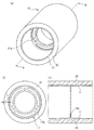
- FIG. 1 is a perspective view schematically showing an example of a hulling roll of the present invention
- (b) is a front view of the hulling roll shown in (a)
- (c) is an AA view of (a). It is line sectional drawing. It is a schematic diagram for demonstrating the usage method of the hulling roll of this invention.
- the hulling roll of the present invention is a hulling roll provided with a shin material part and a rubber layer laminated on the outer peripheral surface of the shin material part, and the rubber layer comprises a polyol component, an isocyanate component, a crosslinking agent, and a silicone oil.
- the isocyanate component is TDI and / or MDI
- the silicone oil has a kinematic viscosity at 25 ° C.
- the above-mentioned isocyanate component is a cured product of a thermosetting urethane composition containing
- the content of the silicone oil in the thermosetting urethane composition is 0.3 to 10.0% by weight based on a total amount 100 of the polyol component, the isocyanate component and the crosslinking agent.
- FIG. 1 (a) is a perspective view which shows typically an example of the hulling roll of this invention
- (b) is a front view of the hulling roll shown to (a)
- (c) is A of (a).
- FIG. A hulling roll 10 shown in FIGS. 1 (a) to 1 (c) includes a metallic reinforced material portion 11 and a rubber layer 12 laminated on the outer peripheral surface of the reinforced material portion 11.
- the shin material part 11 is a cylindrical member provided with an attachment flange 11a for attaching the hulling roll 10 to the hulling machine in the cylinder.
- a rubber layer 12 having a uniform thickness is formed on the entire outer peripheral surface of the shin part 11.
- the structural member of the hulling roll of this invention is demonstrated.
- the above-mentioned shin material part the same sinter material part used in a conventionally known hulling roll can be used.
- the material for the shin material part include aluminum, stainless steel, iron, molybdenum, and titanium.
- the shape and size of the above-mentioned shin material part are not particularly limited, and can be appropriately set according to the specifications of the hulling machine to which the hulling roll is attached and JIS standards (JIS B 9214: rubber roll for rice hulls) as in the conventional product. Good.
- the rubber layer is composed of a cured product of a thermosetting urethane composition containing a polyol component, an isocyanate component, a crosslinking agent, and a silicone oil, and the kinematic viscosity of the silicone oil at 25 ° C. is 10 to 3000 mm 2 / s. is there.
- the durability (abrasion resistance) of the rubber layer can be remarkably improved by containing the silicone oil in the above range in the thermosetting urethane composition.
- the kinematic viscosity at 25 ° C. of the silicone oil is less than 10 mm 2 / s, or when the kinematic viscosity exceeds 3000 mm 2 / s, the durability of the rubber layer is significantly reduced. .
- the hulling roll of this invention is aiming at the improvement of water resistance by containing silicone oil in a thermosetting urethane composition so that it may mention later.
- silicone oil when the kinematic viscosity of the silicone oil is less than 10 mm 2 / s, the initial water resistance of the rubber layer can be secured, but the water resistance after the rubber layer is worn becomes insufficient. There is. Further, when the kinematic viscosity of the silicone oil is less than 10 mm 2 / s, bleeding of the silicone oil may occur. If bleed of silicone oil occurs, brown rice will be soiled or rice husks may adhere to the rice huller during rice hulling.
- thermosetting urethane composition when the said kinematic viscosity of silicone oil exceeds 3000 mm ⁇ 2 > / s, handling will become difficult and it will become difficult to mix silicone oil uniformly when preparing a thermosetting urethane composition.
- the hulling roll provided with a rubber layer made of a cured product of a thermosetting urethane composition in which silicone oil is not uniformly mixed is deteriorated in durability of the hulling roll, uneven wear occurs in the rubber layer, The removal rate at the time of hulling may decrease.
- the hulling roll of the present invention achieves an improvement in the durability of the rubber layer by blending silicone oil into the thermosetting urethane composition. At this time, it is important not to simply mix the silicone oil but to mix the silicone oil having the specific kinematic viscosity described above. Thus, the knowledge that the durability of the rubber layer can be specifically improved by blending a silicone oil having a specific kinematic viscosity is a knowledge newly found by the present inventors. is there.
- the content of the silicone oil is 0.3 to 10.0% by weight based on the total amount of the polyol component, the isocyanate component and the crosslinking agent.
- the content of the silicone oil is less than 0.3% by weight, sufficient water resistance cannot be imparted to the rubber layer.
- the hulling roll of the present invention is intended to improve the durability of the rubber layer by adding silicone oil to the thermosetting urethane composition, but the silicone oil content is 0.3. If it is less than% by weight, the durability cannot be sufficiently improved. On the other hand, when the content of the silicone oil exceeds 10% by weight, the silicone oil bleeds although the durability and water resistance are good.
- the content of the silicone oil is preferably 0.5 to 5.0% by weight, more preferably 0.7 to 2.5% by weight, based on the total amount of the polyol component, the isocyanate component and the crosslinking agent.
- a rubber composition is formed using a thermosetting urethane composition containing silicone oil, and the silicone oil is dispersed throughout the rubber layer. Therefore, even if the rubber layer is worn by using a hulling roll, the hydrophobicity of the surface of the rubber layer is always ensured by silicone oil, and after manufacturing, excellent water resistance is maintained until the hulling roll is used up. be able to. Therefore, even if the hulling machine of the present invention is attached to the hulling machine and the hulling machine interrupts the operation for a long time, the rubber layer deteriorates at the time of interruption and the performance of the hulling roll is lowered. Can be avoided.
- the silicone oil is not particularly limited.
- dimethyl silicone oil methylphenyl silicone oil, methyl hydrogen silicone oil, modified silicone oil in which an organic group is introduced into the side chain and / or terminal of these silicone oils (for example, And silanol group-end-modified silicone oil).
- dimethyl silicone oil is preferred.
- Dimethyl silicone oil has a relatively simple structure among silicone oils and has no significant steric hindrance. Therefore, dimethyl silicone oil is easy to disperse in polyurethane molecules when dispersed in a urethane composition, and is a thermosetting urethane. Suitable for homogenizing the cured product.
- silicone oil having a site that can be sterically hindered such as modified silicone oil, is not incorporated into the entanglement of polyurethane molecules, and the silicone oil is localized in the cured product of the thermosetting urethane composition. May end up.
- silicone oil may be localized near the surface of the rubber layer.
- the thermosetting urethane composition contains TDI and / or MDI as the isocyanate component.
- TDI can be used as the TDI (tolylene diisocyanate).
- the mixing ratio of 2,4-TDI and 2,6-TDI (2,4-TDI / 2,6-TDI) is not particularly limited, but 65/35 to 80/20 (weight ratio) is preferable.
- Various commercially available products can also be used as the TDI.
- the MDI (diphenylmethane diisocyanate or polymethylene polyphenylene polyisocyanate) is not particularly limited, and can be used regardless of the molecular weight distribution thereof.
- pure MDI (4,4′-MDI), polymeric MDI, etc. Can be used.
- Various commercially available products can also be used as the MDI.
- the isocyanate group concentration in the thermosetting urethane composition is preferably 1.2 to 4.5% by weight. If the isocyanate group concentration is less than 1.2% by weight, the abrasion resistance of the cured product may be lowered. On the other hand, if the isocyanate group concentration exceeds 4.5% by weight, the cured product may be too hard.
- concentration (weight%) means the weight ratio of the isocyanate group contained in the total amount of an isocyanate component, a polyol component, and a crosslinking agent.
- the polyol component is not particularly limited as long as it is a polyol component conventionally used for the synthesis of polyurethane, and examples thereof include polyester polyol, polyether polyol, polycaprolactone polyol, and the like. Of these, polyester polyol is preferred. This is because a rubber layer having excellent abrasion resistance can be formed by a high intermolecular force expressed by a highly polar polyester polyol group.
- polyester polyol examples include those obtained by reacting dicarboxylic acid and glycol according to a conventional method.
- dicarboxylic acid include aromatic dicarboxylic acids such as terephthalic acid, isophthalic acid, and 2,6-naphthalenedicarboxylic acid, aliphatic dicarboxylic acids such as adipic acid, azelaic acid, and sebacic acid, and oxycarboxylic acids such as oxybenzoic acid. Examples thereof include acids and ester-forming derivatives thereof. Of these, adipic acid is preferred, and adipic acid is particularly preferred when 1,4-butanediol is used as the glycol or crosslinking agent.
- adipic acid Since the C atom arrangement of adipic acid is the same quadruple arrangement as 1,4-butanediol, it is excellent in oriented crystallinity and exhibits a strong intermolecular force by having a crystallized structure. Moreover, since adipic acid is cheap, it is economically excellent.
- the said dicarboxylic acid may be used independently and may be used together 2 or more types.
- glycol examples include aliphatic glycols such as ethylene glycol, 1,4-butanediol, diethylene glycol, neopentyl glycol, 3-methyl-1,5-pentanediol, 1,9-nonanediol, and triethylene glycol.
- an aliphatic glycol is preferable, and ethylene glycol and 1,4-butanediol are more preferable.
- the polyester polyol which is a reaction product of dicarboxylic acid and glycol, has a linear structure, but may be a branched polyester using a trivalent or higher valent ester-forming component.
- the above glycols may be used alone or in combination of two or more.
- polyester polyol polyethylene adipate polyester polyol, polybutylene adipate polyester, and polyethylene butylene adipate polyester are particularly preferable. It has a molecular structure suitable for forming a rubber layer having a JIS-A hardness of about 90 ° and is inexpensive.
- polyether polyol examples include polyalkylene glycols such as polyethylene glycol, polypropylene glycol, polytetramethylene glycol, and copolymers thereof. Of these, polytetramethylene glycol is preferred from the viewpoint of good wear resistance.
- polycaprolactone polyol examples include those obtained by ring-opening addition of ⁇ -caprolactone using a low molecular weight glycol as an initiator in the presence of a catalyst.
- a low molecular weight glycol divalent alcohols such as ethylene glycol, propylene glycol, 1,3-butylene glycol and neopentyl glycol and trivalent alcohols such as trimethylene glycol and glycerin are preferably used.
- the catalyst examples include organic titanium compounds such as tetrabutyl titanate, tetrapropyl titanate, and tetraethyl titanate, tin compounds such as tin octylate, dibutyltin oxide, dibutyltin laurate, stannous chloride, and stannous bromide. Preferably used.
- organic titanium compounds such as tetrabutyl titanate, tetrapropyl titanate, and tetraethyl titanate
- tin compounds such as tin octylate, dibutyltin oxide, dibutyltin laurate, stannous chloride, and stannous bromide.
- ⁇ -caprolactone other cyclic lactones such as trimethylcaprolactone and valerolactone may be partially mixed.
- the above-described polyols may be used alone or in combination of two or more.
- the polyol preferably has a number average molecular weight of 1000 to 3000. If the number average molecular weight is less than 1000, the rubber layer may not exhibit satisfactory rubber elasticity and may have high rigidity. On the other hand, if the number average molecular weight exceeds 3000, the rubber layer may not be provided with satisfactory rubber strength, and the rubber layer may be too flexible.
- the number average molecular weight is a measured value in terms of polystyrene by GPC (gel permeation chromatograph) measurement.
- crosslinking agent examples include 1,4-butanediol (1,4-BD), 1,4-bis ( ⁇ -hydroxyethoxy) benzene (BHEB), ethylene glycol, propylene glycol, hexanediol, diethylene glycol, triethylene glycol, and the like.
- Methylolpropane (TMP) glycerin, 4,4′-methylenebis (2-chloroaniline), hydrazine, ethylenediamine, diethylenetriamine, 4,4′-diaminodiphenylmethane, 4,4′-diaminodicyclohexylmethane, N, N-bis ( 2-hydroxypropyl) aniline, water and the like.
- 1,4-butanediol and BHEB are preferable because appropriate rubber hardness and rubber rigidity are easily exhibited.
- a thermosetting urethane composition containing 1,4-butanediol or BHEB has a relatively long pot life and can be molded by hand casting.
- the said crosslinking agent may be used independently and may be used together 2 or more types.
- the crosslinking agent preferably contains at least 1,4-butanediol. This is because it is suitable for improving durability.
- thermosetting urethane composition further includes chain extenders, reaction aids such as crosslinking accelerators and crosslinking retarders, hydrolysis inhibitors, reinforcing materials such as inorganic fibers and inorganic fillers, colorants, light stabilizers, Various additives such as a heat stabilizer, an antioxidant, an antifungal agent, a flame retardant, and a filler (a bulking agent) may be contained as necessary.
- reaction aids such as crosslinking accelerators and crosslinking retarders, hydrolysis inhibitors, reinforcing materials such as inorganic fibers and inorganic fillers, colorants, light stabilizers,
- Various additives such as a heat stabilizer, an antioxidant, an antifungal agent, a flame retardant, and a filler (a bulking agent) may be contained as necessary.
- the rubber layer (cured product of the thermosetting urethane composition) preferably has a JIS-A hardness at 20 ° C. of 85 ° or more.
- the JIS-A hardness is more preferably 88 ° or more, and still more preferably 90 ° or more.
- the JIS-A hardness at 20 ° C. of the rubber layer is preferably less than 99 °. If it exceeds 99 °, the rice may be damaged at the time of scouring, and the occurrence rate of so-called broken rice may increase.
- the JIS-A hardness of the rubber layer is preferably about 88 to 92 ° when the rice to be crushed is relatively soft japonica rice or the like, and the rice to be crushed is a relatively hard Indica rice. In the case of rice or the like, it is preferably about 92 to 96 °.
- the JIS-A hardness may be measured according to JIS K 6253 cited in JIS K 9124 (however, the measurement temperature is 20 ° C.).
- the “rubber layer” in the present invention corresponds to the “rubber part” referred to in JIS K 9124.
- the rubber layer (cured product of the thermosetting urethane composition) preferably has a tan ⁇ peak temperature (Tg) of 10 ° C. or lower. This is because appropriate rubber elasticity is exhibited at the temperature of the rubber layer at the time of use of 30 to 50 ° C.
- the rubber layer (cured product of the thermosetting urethane composition) preferably has a DIN wear loss of 40 to 100 mm 3 . If the DIN wear loss is less than 40 mm 3 , the occurrence rate of crushed rice may be high during rice milling. On the other hand, if the DIN wear loss exceeds 100 mm 3 , the durability becomes insufficient.
- the DIN wear loss may be measured according to the DIN wear test of JIS K 6264. The DIN wear loss is more preferably 40 to 85 mm 3 .
- the thickness of the rubber layer is not particularly limited, and may be set as appropriate according to the specifications of the hulling machine to which the hulling roll is attached and the JIS standard (JIS B 9214), as in the conventional product.
- the thickness of the rubber layer (indicated by T in FIG. 1B) refers to a value that is 1 ⁇ 2 of the difference between the outer diameter and inner diameter of the rubber layer when not in use.
- a primer layer and / or an adhesive layer is formed between the sinter material part and the rubber layer in order to further improve the adhesion between the sinter material part and the rubber layer.
- a surface treatment for improving the adhesion to the rubber layer may be applied.
- the adhesive can be formed using, for example, a phenol-based adhesive or the like.
- the primer layer can be formed using, for example, a urethane-based, polyester-based, silane-based, polyamide-based or phenol-based primer, a silane coupling agent, or the like.
- the surface treatment include formation of a roughened surface.
- the roughened surface may be formed by, for example, blasting, grinding, etching, plating, polishing, oxidation, or the like.
- the roundness of the cross section (cross section perpendicular to the rotation axis in use) of the hulling roll is 0.5 mm or less.
- the roundness exceeds 0.5 mm, the variation in the spacing between the hulling rolls during use increases, and the removal rate may decrease or the occurrence rate of broken rice may increase.
- the hulling roll can be manufactured, for example, through the following steps (1) and (2).
- a shin material part is prepared.
- the above-mentioned shin material part can be produced by a conventionally known method, for example, can be produced by aluminum die casting or the like.
- an adhesive layer and / or a primer layer are formed on the outer peripheral surface of the shin material part, or a surface treatment is applied to the outer peripheral surface of the shin material part.
- a rubber layer is formed around the shin material part.
- the shin material part is placed in a cylindrical mold, and then the above-described thermosetting urethane composition is injected into the gap between the outer peripheral surface of the shin material part and the inner wall surface of the mold, A rubber layer is formed by curing under the following curing conditions.
- the curing conditions are not particularly limited, and may be appropriately set according to the composition of the thermosetting urethane composition. Usually, conditions of heating at 100 to 160 ° C. for 30 to 90 minutes can be employed. Further, after performing the curing treatment under the above conditions and removing from the mold, for example, post-curing may be performed at 100 to 160 ° C. for 3 to 48 hours.
- thermosetting urethane composition used in the present invention has a relatively slow curing after preparation.
- FIG. 2 is a schematic diagram for explaining a method of using the hulling roll of the present invention.
- the hulling roll of the present invention is used by attaching two hulling rolls as one set to a conventionally known rubber roll type hulling machine. That is, as shown in FIG. 2, a pair of hulling rolls 10A and 10B are mounted in parallel so as to have a predetermined interval L, and each of hulling rolls 10A and 10B is opposite to each other at different rotational speeds (hulling rolls). Rotate at a rotational speed Va of 10A ⁇ rotational speed Vb of the hulling roll 10B.
- the distance L between the hulling roll 10A and the hulling roll 10B and the rotational speeds (peripheral speeds) Va and Vb of the hulling roll 10A and the hulling roll 10B when using the hulling roll are not particularly limited. May be set as appropriate according to various conditions such as the specifications, the type and the drying rate of dried rice, the processing rate, and the putting rate.
- thermosetting urethane composition 100 parts by weight of urethane prepolymer (Samprene P6814, manufactured by Sanyo Chemical Co., Ltd.) containing MDI as an isocyanate component and polyethylene adipate ester diol (PEA) as a polyol component, silicone oil (manufactured by Toray Dow Corning, SH200-100CS (dimethylsilicone) Oil: kinematic viscosity 100 mm 2 / s)) 1.0 part by weight, yellow pigment (ZA Yellow # 200, manufactured by Mikuni Chemical Co., Ltd.) 0.02 part by weight, and white pigment (ZA White # 2200, Mikuni Chemical Co., Ltd.) (Made) 0.02 part by weight was mixed with an agitator.
- urethane prepolymer Samprene P6814, manufactured by Sanyo Chemical Co., Ltd.
- PEA polyethylene adipate ester diol
- silicone oil manufactured by Toray Dow Corning, SH200-100
- thermosetting urethane composition 1.59 parts by weight of 1,4-butanediol (manufactured by BASF Japan) and 10.50 parts by weight of BHEB (manufactured by Mitsui Chemicals) are additionally mixed with the obtained mixture to obtain a thermosetting urethane composition. (1) was prepared.
- thermosetting urethane composition (2) was prepared in the same manner as in Preparation Example 1 except that the amount of silicone oil was changed to 0.34 parts by weight.
- thermosetting urethane composition (3) was prepared in the same manner as in Preparation Example 1 except that the amount of the silicone oil was changed to 11.2 parts by weight.
- thermosetting urethane composition (4) was prepared in the same manner as in Preparation Example 1, except that the silicone oil was changed to SH200-10CS (dimethyl silicone oil: kinematic viscosity: 10 mm 2 / s) manufactured by Toray Dow Corning. .
- SH200-10CS dimethyl silicone oil: kinematic viscosity: 10 mm 2 / s
- thermosetting urethane composition (5) was prepared in the same manner as in Preparation Example 1, except that the silicone oil was changed to SH200-3000CS (dimethylsilicone oil: kinematic viscosity 3000 mm 2 / s) manufactured by Toray Dow Corning. .
- SH200-3000CS dimethylsilicone oil: kinematic viscosity 3000 mm 2 / s
- thermosetting urethane composition (6) was prepared in the same manner as in Preparation Example 1 except that the amount of silicone oil was changed to 0.56 parts by weight.
- thermosetting urethane composition (7) was prepared in the same manner as in Preparation Example 1 except that the amount of silicone oil was changed to 5.60 parts by weight.
- thermosetting urethane composition (9) was prepared in the same manner as in Preparation Example 1 except that the silicone oil was changed to SH550 (methylphenyl silicone oil: kinematic viscosity 130 mm 2 / s) manufactured by Toray Dow Corning.
- SH550 methylphenyl silicone oil: kinematic viscosity 130 mm 2 / s
- thermosetting urethane composition (12) Preparation except that the amount of 1,4-butanediol was changed to 0.95 parts by weight, the amount of BHEB was changed to 11.90 parts by weight, and the amount of silicone oil was changed to 1.02 parts by weight.
- a thermosetting urethane composition (12) was prepared.
- Preparation Example 13 100 parts by weight of urethane prepolymer (Takenate L-1290, manufactured by Mitsui Chemicals) using TDI as an isocyanate component and polyethylene adipate ester diol (PEA) as a polyol component, silicone oil (manufactured by Dow Corning Toray, SH200-100CS) 1.0 part by weight, 0.02 part by weight of a yellow pigment (ZA Yellow # 200) and 0.02 part by weight of a white pigment (ZA White # 2200) were mixed with an agitator. Next, 12.6 parts by weight of methylenebis (2-chloroaniline) (Ihara Chemical Co., Ltd., Iharacamine MT) was additionally mixed with the resulting mixture to prepare a thermosetting urethane composition (13). .
- methylenebis (2-chloroaniline) Ihara Chemical Co., Ltd., Iharacamine MT
- Preparation Example 14 100 parts by weight of urethane prepolymer (Samprene P6814, manufactured by Sanyo Chemical Co., Ltd.) containing MDI as an isocyanate component and polyethylene adipate ester diol (PEA) as a polyol component, silicone oil (manufactured by Toray Dow Corning, SH200-100CS (dimethylsilicone) Oil: kinematic viscosity 100 mm 2 / s)) 1.02 parts by weight, yellow pigment (ZA Yellow # 200, manufactured by Mikuni Chemical Co., Ltd.) 0.02 parts by weight, and white pigment (ZA White # 2200, Mikuni Chemical Co., Ltd.) (Made) 0.02 part by weight was mixed with an agitator.
- urethane prepolymer Samprene P6814, manufactured by Sanyo Chemical Co., Ltd.
- PEA polyethylene adipate ester diol
- silicone oil manufactured by Toray Dow Corning, SH200-100CS (
- thermosetting urethane composition 14
- 1,4-butanediol manufactured by BASF Japan
- BHEB manufactured by Mitsui Chemicals
- trimethylolpropane manufactured by Mitsubishi Gas Chemical Co., Ltd.
- thermosetting urethane composition (Preparation Example 15) The blending amount of 1,4-butanediol is 0.32 parts by weight, the blending amount of BHEB is 12.02 parts by weight, the blending amount of trimethylolpropane is 0.64 parts by weight, and the blending amount of silicone oil is 1.03 parts by weight.
- a thermosetting urethane composition (15) was prepared in the same manner as in Preparation Example 14 except that the composition was changed to parts.
- thermosetting urethane composition (16) was prepared in the same manner as in Preparation Example 1 except that no silicone oil was blended.
- thermosetting urethane composition (17) was prepared in the same manner as in Preparation Example 1 except that the silicone oil was changed to SH200-2CS (dimethyl silicone oil: kinematic viscosity 2 mm 2 / s) manufactured by Toray Dow Corning. .
- SH200-2CS dimethyl silicone oil: kinematic viscosity 2 mm 2 / s
- thermosetting urethane composition (18) was prepared in the same manner as in Preparation Example 1, except that the silicone oil was changed to SH200-10000CS (dimethylsilicone oil: kinematic viscosity 10000 mm 2 / s) manufactured by Toray Dow Corning. .
- SH200-10000CS dimethylsilicone oil: kinematic viscosity 10000 mm 2 / s
- thermosetting urethane composition (19) was prepared in the same manner as in Preparation Example 1 except that the amount of silicone oil was changed to 0.22 parts by weight.
- thermosetting urethane composition (20) was prepared in the same manner as in Preparation Example 1 except that the amount of silicone oil was changed to 13.5 parts by weight.
- thermosetting urethane composition (21) was prepared in the same manner as in Preparation Example 10 except that no silicone oil was blended.
- thermosetting urethane composition (22) was prepared in the same manner as in Preparation Example 11 except that no silicone oil was added.
- thermosetting urethane composition (23) was prepared in the same manner as in Preparation Example 13 except that no silicone oil was added.
- hulling roll (1) (Example 1)
- a type: integrated large 60 type hulling roll was produced.
- the shin material part having the shape shown in FIG. 1 was cast by aluminum die casting.
- the above-mentioned shin material part was installed in a cylindrical mold so that the distance between the outer peripheral surface of the above-mentioned sinter material part and the inner peripheral surface of the above-mentioned mold was almost equal.
- the thermosetting urethane composition (1) is injected into the gap between the outer peripheral surface of the above-mentioned shin material part and the inner peripheral surface of the above-mentioned mold, and cured under the following conditions to obtain an outer diameter dimension and a width dimension.
- a hulling roll in which a rubber layer was laminated on the outer peripheral surface of the above-mentioned shin material part was produced.
- thermosetting urethane composition (1) The temperature of the thermosetting urethane composition (1) at the time of pouring was set to 105 ° C. and cured at a mold temperature of 130 ° C. for 60 minutes. Thereafter, the mold was removed from the mold, and post-curing was performed at 110 ° C. for 24 hours.
- Examples 2 to 10 and 12 A hulling roll is produced in the same manner as in Example 1 except that any of the thermosetting urethane compositions (2) to (10) and (12) is used in place of the thermosetting urethane composition (1). did.
- thermosetting urethane composition (11) was used instead of the thermosetting urethane composition (1) and the composition was cured under the following conditions.
- the temperature of the thermosetting urethane composition (11) at the time of pouring was set to 105 ° C. and cured at a mold temperature of 130 ° C. for 90 minutes. Thereafter, the mold was removed from the mold, and post-curing was performed at 110 ° C. for 24 hours.
- thermosetting urethane composition (13) was used instead of the thermosetting urethane composition (1) and the composition was cured under the following conditions.
- the temperature of the thermosetting urethane composition (13) at the time of pouring was set to 85 ° C. and cured at a mold temperature of 130 ° C. for 60 minutes. Thereafter, the mold was removed from the mold, and post-curing was performed at 110 ° C. for 24 hours.
- thermosetting urethane composition (14) was used in place of the thermosetting urethane composition (1) and the composition was cured under the following conditions.
- the temperature of the thermosetting urethane composition (14) at the time of pouring was set to 105 ° C. and cured at a mold temperature of 130 ° C. for 60 minutes. Thereafter, the mold was removed from the mold, and post-curing was performed at 110 ° C. for 24 hours.
- Example 15 A hull roll was produced in the same manner as in Example 14 except that the thermosetting urethane composition (15) was used instead of the thermosetting urethane composition (14).
- thermosetting urethane compositions (16) to (21) was used instead of the thermosetting urethane composition (1).
- thermosetting urethane composition (22) was used instead of the thermosetting urethane composition (11).
- thermosetting urethane composition (23) was used instead of the thermosetting urethane composition (13).
- JIS-A Hardness The JIS-A hardness of the rubber layer formed on the hulling roll produced in Examples 1 to 15 and Comparative Examples 1 to 8 is based on JIS K 6253 cited in JIS K 9124. Measured. However, the measurement temperature was 20 ° C., and the measurement locations were three locations. The results are shown in Table 3.
- the contact angle was measured using the automatic contact angle meter DMe-200 manufactured by Kyowa Interface Science Co., Ltd., and the glass test piece in JIS R 3257 “Testing method for wettability of substrate glass surface” by measuring the above DIN wear loss It replaced with the test piece used and measured by the sessile drop method. In this evaluation, the larger the contact angle, the more hydrophobic the surface and the better the water resistance.
- hulling roll (2) (Example 16)
- a type: integrated 100 type hulling roll was produced.
- the hulling roll was produced using the method similar to Example 1 except having changed the shape and the dimension.
- the relationship between the hulling amount and the abrasion amount of the rubber layer was evaluated by Inami Country Elevator (Hyogo Minami Agricultural Cooperative).
- the hulling machine used was Satake Co., Ltd., model: HPS-100HEA (introduced in 1999).
- Sticky rice was brand: Kinuhikari and moisture content (based on brown rice) 14.1 to 14.3%.
- the processing speed was about 2.5 tons / hour. Note that the removal rate in this example was 79%.
- Example 17 In this example, a type: integrated 100 type hulling roll was produced. Here, the hulling roll was produced using the same method as Example 12 except having changed the shape and dimension.
- Example 18 In this example, a type: integrated 100 type hulling roll was produced. Here, the hulling roll was produced using the method similar to Example 13 except having changed the shape and the dimension.
- Example 19 In this example, a type: integrated 100 type hulling roll was produced. Here, the hulling roll was produced using the method similar to Example 14 except having changed the shape and dimension.
- the relationship between the hulling amount and the abrasion amount of the rubber layer was evaluated by the Hidaka Country Elevator (Tajima Agricultural Cooperative).
- Hidaka Country Elevator Tajima Agricultural Cooperative
- As the hulling machine an integrated 100-type roll milling machine (introduced in 1972) manufactured by Satake Co., Ltd. was used.
- Sticky rice was brand: Koshihikari, moisture content (based on brown rice): 14.2 to 14.6%.
- the processing speed was about 2.8 tons / hour. Note that the removal rate in this example was 78%.
- Example 20 In this example, a type: integrated 100 type hulling roll was produced. Here, the hulling roll was produced using the method similar to Example 15 except having changed the shape and the dimension.
- the relationship between the hulling amount and the abrasion amount of the rubber layer was evaluated by the Hidaka Country Elevator (Tajima Agricultural Cooperative).
- Hidaka Country Elevator Tajima Agricultural Cooperative
- As the hulling machine an integrated 100-type roll milling machine (introduced in 1972) manufactured by Satake Co., Ltd. was used.
- Sticky rice was brand: Koshihikari, moisture content (based on brown rice): 14.2 to 14.6%.
- the processing speed was about 2.8 tons / hour. Note that the removal rate in this example was 78%.
- Comparative Example 9 a type: integrated 100 type hulling roll was produced.
- the hulling roll was produced using the method similar to the comparative example 1 except having changed the shape and dimension.
- Izushi country elevator (Tajima agricultural cooperative) evaluated the relationship between the hulling amount and the abrasion amount of the rubber layer.
- hulling machine an integrated 100 type roll milling machine (introduced in 1972) manufactured by Satake Co., Ltd. was used.
- Sticky rice was brand: Koshihikari, moisture content (based on brown rice) 14.8 to 15.0%.
- the processing speed was about 2.5 tons / hour.
- the removal rate of this comparative example was 79%.
- Comparative Example 10 a type: integrated 100 type hulling roll was produced.
- the hulling roll was produced using the method similar to the comparative example 6 except having changed the shape and dimension.
- Izushi country elevator (Tajima agricultural cooperative) evaluated the relationship between the hulling amount and the abrasion amount of the rubber layer.
- hulling machine an integrated 100 type roll milling machine (introduced in 1972) manufactured by Satake Co., Ltd. was used.
- Sticky rice was brand: Koshihikari, moisture content (based on brown rice) 14.8 to 15.0%.
- the processing speed was about 2.5 tons / hour.
- the removal rate of this comparative example was 79%.
- the hulling roll of the present invention provided with a rubber layer made of a cured product of a thermosetting urethane composition containing a predetermined amount of silicone oil having a specific kinematic viscosity is excellent in durability, so that It has become clear that the frequency of replacement of the hulling roll can be reduced.
Landscapes
- Polyurethanes Or Polyureas (AREA)
- Adjustment And Processing Of Grains (AREA)
- Compositions Of Macromolecular Compounds (AREA)
Abstract
本発明は耐久性及び耐水性に優れるゴム組成物を備えた籾摺りロールに関し、本発明の籾摺りロールは、しん材部と、上記しん材部の外周面に積層されたゴム層とを備えた籾摺りロールであって、上記ゴム層は、ポリオール成分、イソシアネート成分、架橋剤及びシリコーンオイルを含有する熱硬化性ウレタン組成物の硬化物からなり、上記イソシアネート成分は、TDI及び/又はMDIであり、上記シリコーンオイルは、25℃での動粘度が10~3000mm2/sであり、上記熱硬化性ウレタン組成物における上記シリコーンオイルの含有量は、ポリオール成分、イソシアネート及び架橋剤の合計量に対して、0.3~10.0重量%である。
Description
本発明は、籾摺りロールに関する。
農業用脱穀機には籾摺りロールが取り付けられている。この籾摺りロールは、2個の籾摺りロールを一対とし、籾摺りロール同士が所定の間隔を有するように配置して使用する。このように配置された一対の籾摺りロールでは、各籾摺りロールを異なる周速度で回転させつつ、籾摺りロール同士の隙間に籾米(籾殻が付いた米)を投入することにより、籾殻を脱ぷし、籾殻と玄米とに分離することができる。
上記籾摺りロールとしては、円筒状のしん材部とその周囲に設けられたゴム部とからなるロール部材が一般に使用されている(例えば、特許文献1参照)。
上記ゴム部は、例えば、ニトリルゴム(NBR)やスチレン・ブタジエンゴム(SBR)等の合成ゴムを用いて形成されている。
上記ゴム部は、例えば、ニトリルゴム(NBR)やスチレン・ブタジエンゴム(SBR)等の合成ゴムを用いて形成されている。
籾摺りロールは、上述したような構成を備えているため、籾殻の脱ぷに伴いゴム部が徐々に摩耗していくこととなり、ゴム層の厚さが薄くなると籾摺りロールとしての性能を発揮することができなくなる。そのため、ゴム層の厚さが設定値に到達した場合には、籾摺りロールを交換する必要があった。
そのため、長期間に渡って籾摺りロールを交換することなく籾殻を脱ぷするために、耐久性(耐摩耗性)に優れたゴム層を備えた籾摺りロールが求められている。しかしながら、特許文献1に記載の籾摺りロールは、ゴム層の耐久性が充分ではなかった。
そのため、長期間に渡って籾摺りロールを交換することなく籾殻を脱ぷするために、耐久性(耐摩耗性)に優れたゴム層を備えた籾摺りロールが求められている。しかしながら、特許文献1に記載の籾摺りロールは、ゴム層の耐久性が充分ではなかった。
耐久性に優れた籾摺りロールとして、例えば、特許文献2、3には、ウレタン樹脂を用いて作製されたゴム層を備えた籾摺りロールが提案されており、ゴム層がウレタン樹脂製のため、耐久性に優れるとされている。
特許文献1に記載された籾摺りロールは、上述したように、ゴム層の耐久性(耐摩耗性)が不充分であった。そのため、頻繁に籾摺りロールを交換しなければならないとの問題があった。
また、特許文献2、3に記載された籾摺りロールは、ゴム層がウレタン組成物を用いて形成されているため、NBR製やSBR製のゴム層を備えた籾摺りロールに比べると耐久性に優れる傾向にある。
しかしながら、その耐久性については更なる向上が望まれていた。
また、特許文献2、3に記載された籾摺りロールは、ゴム層がウレタン組成物を用いて形成されているため、NBR製やSBR製のゴム層を備えた籾摺りロールに比べると耐久性に優れる傾向にある。
しかしながら、その耐久性については更なる向上が望まれていた。
また、ウレタン組成物からなるゴム層を備えた籾摺りロールは、ウレタン樹脂が加水分解により劣化しやすく、ゴム層の耐水性(耐湿気性)がNBR製やSBR製のゴム層に比べて劣るため、長期間保管した後の籾摺りロールを使用すると、籾摺りロールの性能が低下していることがあった。また、籾摺りロールは、時期(季節)によって使用頻度が異なる為、籾摺りロールを取り付けた籾摺り機の稼働を長期に渡って中断することがある。この場合も、ゴム層がウレタン組成物を用いて形成されていると、籾摺り機を再稼働した際にゴム層の劣化により、所定の性能を発揮することができないことがあった。
本発明者らは上記課題を解決すべく検討を行い、特定の動粘度のシリコーンオイルを所定量含有する熱硬化性ウレタン組成物の硬化物からなるゴム層を備えた籾摺りロールが、耐久性及び耐水性に優れることを見出し、本発明を完成した。
本発明の籾摺りロールは、しん材部と、上記しん材部の外周面に積層されたゴム層とを備えた籾摺りロールであって、
上記ゴム層は、ポリオール成分、イソシアネート成分、架橋剤及びシリコーンオイルを含有する熱硬化性ウレタン組成物の硬化物からなり、
上記イソシアネート成分は、TDI及び/又はMDIであり、
上記シリコーンオイルは、25℃での動粘度が10~3000mm2/sであり、
上記熱硬化性ウレタン組成物における上記シリコーンオイルの含有量は、ポリオール成分、イソシアネート成分及び架橋剤の合計量に対して、0.3~10.0重量%であることを特徴とする。
上記ゴム層は、ポリオール成分、イソシアネート成分、架橋剤及びシリコーンオイルを含有する熱硬化性ウレタン組成物の硬化物からなり、
上記イソシアネート成分は、TDI及び/又はMDIであり、
上記シリコーンオイルは、25℃での動粘度が10~3000mm2/sであり、
上記熱硬化性ウレタン組成物における上記シリコーンオイルの含有量は、ポリオール成分、イソシアネート成分及び架橋剤の合計量に対して、0.3~10.0重量%であることを特徴とする。
本発明の籾摺りロールは、特定の動粘度のシリコーンオイルが所定量配合された熱硬化性ウレタン組成物の硬化物からなるゴム層を備えており、上記ゴム層は、シリコーンオイルを含有しているため、耐久性(耐摩耗性)及び耐水性(耐湿気性)に優れる。
よって、本発明の籾摺りロールは長期間に渡って交換することなく使用することができる。
また、本発明の籾摺りロールは、耐水性に優れるため、使用前の保管時や、籾摺りロールを籾摺り機に取り付けた後の籾摺り機の停止中(使用中断中)等に、水分の吸湿によるゴム層の劣化を抑制することができる。よって、本発明の籾摺りロールは、長期間に渡って安定した性能を確保することができる。
よって、本発明の籾摺りロールは長期間に渡って交換することなく使用することができる。
また、本発明の籾摺りロールは、耐水性に優れるため、使用前の保管時や、籾摺りロールを籾摺り機に取り付けた後の籾摺り機の停止中(使用中断中)等に、水分の吸湿によるゴム層の劣化を抑制することができる。よって、本発明の籾摺りロールは、長期間に渡って安定した性能を確保することができる。
本発明の籾摺りロールにおいて、上記シリコーンオイルは、ジメチルポリシロキサンであることが好ましい。
また、本発明の籾摺りロールにおいて、上記架橋剤は、少なくとも1,4-BD(1,4-ブタンジオール)であることが好ましい。
また、本発明の籾摺りロールにおいて、上記架橋剤は、少なくとも1,4-BD(1,4-ブタンジオール)であることが好ましい。
本発明の籾摺りロールは、ゴム層が特定の動粘度のシリコーンオイルを所定量含有する熱硬化性ウレタン組成物の硬化物からなるため、耐久性及び耐水性に優れる。そのため、長期間に渡って優れた性能を維持したまま交換することなく使用することができる。
また、本発明の籾摺りロールは、長期保管にも適している。
また、本発明の籾摺りロールは、長期保管にも適している。
以下、本発明の実施の形態について、図面を参照しながら説明する。
本発明の籾摺りロールは、しん材部と上記しん材部の外周面に積層されたゴム層とを備えた籾摺りロールであって、上記ゴム層は、ポリオール成分、イソシアネート成分、架橋剤及びシリコーンオイルを含有する熱硬化性ウレタン組成物の硬化物からなり、上記イソシアネート成分は、TDI及び/又はMDIであり、上記シリコーンオイルは、25℃での動粘度が10~3000mm2/sであり、上記熱硬化性ウレタン組成物における上記シリコーンオイルの含有量は、ポリオール成分、イソシアネート成分及び架橋剤の合計量100に対して、0.3~10.0重量%であることを特徴とする。
本発明の籾摺りロールは、しん材部と上記しん材部の外周面に積層されたゴム層とを備えた籾摺りロールであって、上記ゴム層は、ポリオール成分、イソシアネート成分、架橋剤及びシリコーンオイルを含有する熱硬化性ウレタン組成物の硬化物からなり、上記イソシアネート成分は、TDI及び/又はMDIであり、上記シリコーンオイルは、25℃での動粘度が10~3000mm2/sであり、上記熱硬化性ウレタン組成物における上記シリコーンオイルの含有量は、ポリオール成分、イソシアネート成分及び架橋剤の合計量100に対して、0.3~10.0重量%であることを特徴とする。
図1(a)は本発明の籾摺りロールの一例を模式的に示す斜視図であり、(b)は(a)に示した籾摺りロールの正面図であり、(c)は(a)のA-A線断面図である。
図1(a)~(c)に示す籾摺りロール10は、金属製のしん材部11と、しん材部11の外周面に積層されたゴム層12とからなる。
しん材部11は、筒内に籾摺りロール10を籾摺り機に取り付けるための取付用フランジ11aが設けられた円筒状の部材である。
しん材部11に外周面の全体には均一な厚さでゴム層12が形成されている。
図1(a)~(c)に示す籾摺りロール10は、金属製のしん材部11と、しん材部11の外周面に積層されたゴム層12とからなる。
しん材部11は、筒内に籾摺りロール10を籾摺り機に取り付けるための取付用フランジ11aが設けられた円筒状の部材である。
しん材部11に外周面の全体には均一な厚さでゴム層12が形成されている。
以下、本発明の籾摺りロールの構成部材について説明する。
上記しん材部としては、従来公知の籾摺りロールで使用されているしん材部と同様のものを用いることができる。上記しん材部に材質としては、例えば、アルミニウム、ステンレス、鉄、モリブデン、チタン等が挙げられる。
また、上記しん材部の形状やサイズは特に限定されず、従来品と同様、籾摺りロールを取り付ける籾摺り機の仕様や、JIS規格(JIS B 9214:もみすり用ゴムロール)に合わせて適宜設定すればよい。
上記しん材部としては、従来公知の籾摺りロールで使用されているしん材部と同様のものを用いることができる。上記しん材部に材質としては、例えば、アルミニウム、ステンレス、鉄、モリブデン、チタン等が挙げられる。
また、上記しん材部の形状やサイズは特に限定されず、従来品と同様、籾摺りロールを取り付ける籾摺り機の仕様や、JIS規格(JIS B 9214:もみすり用ゴムロール)に合わせて適宜設定すればよい。
上記ゴム層は、ポリオール成分、イソシアネート成分、架橋剤及及びシリコーンオイルを含有する熱硬化性ウレタン組成物の硬化物からなり、上記シリコーンオイルの25℃での動粘度が10~3000mm2/sである。
本発明の籾摺りロールでは、上記範囲のシリコーンオイルを上記熱硬化性ウレタン組成物に含有させることにより、ゴム層の耐久性(耐摩耗性)を格別向上させることができる。
これに対して、上記シリコーンオイルの25℃での動粘度が10mm2/s未満の場合や、上記動粘度が3000mm2/sを超える場合には、ゴム層の耐久性が著しく低下してしまう。
本発明の籾摺りロールでは、上記範囲のシリコーンオイルを上記熱硬化性ウレタン組成物に含有させることにより、ゴム層の耐久性(耐摩耗性)を格別向上させることができる。
これに対して、上記シリコーンオイルの25℃での動粘度が10mm2/s未満の場合や、上記動粘度が3000mm2/sを超える場合には、ゴム層の耐久性が著しく低下してしまう。
更に、本発明の籾摺りロールは、後述するように、シリコーンオイルを熱硬化性ウレタン組成物に含有させることにより、耐水性の向上を図っている。ここで、シリコーンオイルの上記動粘度が10mm2/s未満の場合には、ゴム層の初期の耐水性は確保することができるものの、ゴム層が摩耗した後の耐水性が不充分になることがある。また、シリコーンオイルの上記動粘度が10mm2/s未満の場合には、シリコーンオイルのブリードが発生することがある。シリコーンオイルのブリードが発生すると、籾摺り時に、玄米を汚してしまったり、籾殻が籾摺り機に付着してしまったりすることになる。
また、シリコーンオイルの上記動粘度が3000mm2/sを超えると、取り扱いが困難になり、熱硬化性ウレタン組成物を調製する際に、シリコーンオイルを均一に混合することが困難となる。シリコーンオイルが均一に混合されていない熱硬化性ウレタン組成物の硬化物からなるゴム層を備えた籾摺りロールは、籾摺りロールの耐久性が低下したり、ゴム層に不均一な摩耗が生じたり、籾摺り時の脱ぷ率が低下したりすることがある。
本発明の籾摺りロールは、シリコーンオイルを熱硬化性ウレタン組成物に配合することにより、ゴム層の耐久性の向上を達成している。このとき、単にシリコーンオイルを配合するのではなく、上述した特定の動粘度を有するシリコーンオイルを配合することが重要である。このように、特定の動粘度を有するシリコーンオイルを配合することにより、特異的にゴム層の耐久性を向上させることができるとの知見は、本発明者らによって新たに見出された知見である。
上記熱硬化性ウレタン組成物において、上記シリコーンオイルの含有量は、ポリオール成分、イソシアネート成分及び架橋剤の合計量に対して、0.3~10.0重量%である。
上記シリコーンオイルの含有量が0.3重量%未満では、ゴム層に充分な耐水性を付与することができない。また、上述した通り、本発明の籾摺りロールは、熱硬化性ウレタン組成物にシリコーンオイルを含有させることにより、ゴム層の耐久性の向上を図っているが、シリコーンオイルの含有量が0.3重量%未満では、耐久性を充分に向上させることができない。
一方、上記シリコーンオイルの含有量が10重量%を超えると、耐久性及び耐水性は良好となるものの、シリコーンオイルのブリードが発生してしまう。シリコーンオイルのブリードが発生すると、上述した不都合が生じる。
上記シリコーンオイルの含有量は、ポリオール成分、イソシアネート成分及び架橋剤の合計量に対して、0.5~5.0重量%が好ましく、0.7~2.5重量%がより好ましい。
上記シリコーンオイルの含有量が0.3重量%未満では、ゴム層に充分な耐水性を付与することができない。また、上述した通り、本発明の籾摺りロールは、熱硬化性ウレタン組成物にシリコーンオイルを含有させることにより、ゴム層の耐久性の向上を図っているが、シリコーンオイルの含有量が0.3重量%未満では、耐久性を充分に向上させることができない。
一方、上記シリコーンオイルの含有量が10重量%を超えると、耐久性及び耐水性は良好となるものの、シリコーンオイルのブリードが発生してしまう。シリコーンオイルのブリードが発生すると、上述した不都合が生じる。
上記シリコーンオイルの含有量は、ポリオール成分、イソシアネート成分及び架橋剤の合計量に対して、0.5~5.0重量%が好ましく、0.7~2.5重量%がより好ましい。
上記シリコーンオイルを配合することにより耐水性が向上する理由は、シリコーンオイルを配合しない場合に比べて、ゴム層の表面の疎水性が強まるため、ゴム層が吸湿しにくく、ポリウレタンの加水分解による劣化が生じにくくなるからと考えられる。
上記籾摺りロールは、シリコーンオイルを含有する熱硬化性ウレタン組成物を用いてゴム組成物が形成されており、ゴム層全体にシリコーンオイルが分散している。そのため、籾摺りロールを使用することによりゴム層が摩耗しても、ゴム層の表面の疎水性はシリコーンオイルにより常に確保されており、製造後、籾摺りロールを使い終わるまで優れた耐水性を維持することができる。
従って、本発明の籾摺りロールは、籾摺り機に取り付けた後、長期間に渡って籾摺り機が稼働を中断しても、中断時に上記ゴム層が劣化して籾摺りロールの性能が低下してしまうことを回避することができる。
従って、本発明の籾摺りロールは、籾摺り機に取り付けた後、長期間に渡って籾摺り機が稼働を中断しても、中断時に上記ゴム層が劣化して籾摺りロールの性能が低下してしまうことを回避することができる。
上記シリコーンオイルとしては特に限定されず、例えば、ジメチルシリコーンオイル、メチルフェニルシリコーンオイル、メチルハイドロジェンシリコーンオイル、これらのシリコーンオイルの側鎖及び/又は末端に有機基を導入した変性シリコーンオイル(例えば、シラノール基末端変性シリコーンオイルなど)等が挙げられる。
これらのなかでは、ジメチルシリコーンオイルが好ましい。ジメチルシリコーンオイルは、シリコーンオイルの中では比較的構造が単純であり、立体的に大きな障害が無いため、ウレタン組成物中に分散させた際に、ポリウレタン分子中に分散しやすく、熱硬化性ウレタン組成物の硬化物を均質にするのに適している。一方、変性シリコーンオイルのように、立体障害となり得る部位を有するシリコーンオイルは、ポリウレタン分子の絡み合いの中にシリコーンオイルが取り込まれず、熱硬化性ウレタン組成物の硬化物においてシリコーンオイルが局在してしまうことがある。例えば、シリコーンオイルがゴム層の表面付近に局在してしまうことがある。
これらのなかでは、ジメチルシリコーンオイルが好ましい。ジメチルシリコーンオイルは、シリコーンオイルの中では比較的構造が単純であり、立体的に大きな障害が無いため、ウレタン組成物中に分散させた際に、ポリウレタン分子中に分散しやすく、熱硬化性ウレタン組成物の硬化物を均質にするのに適している。一方、変性シリコーンオイルのように、立体障害となり得る部位を有するシリコーンオイルは、ポリウレタン分子の絡み合いの中にシリコーンオイルが取り込まれず、熱硬化性ウレタン組成物の硬化物においてシリコーンオイルが局在してしまうことがある。例えば、シリコーンオイルがゴム層の表面付近に局在してしまうことがある。
上記熱硬化性ウレタン組成物は、上記イソシアネート成分として、TDI及び/又はMDIを含有する。
上記TDI(トリレンジイソシアネート)としては従来公知のTDIを用いることができる。上記TDIにおいて、2,4-TDIと2,6-TDIとの配合比(2,4-TDI/2,6-TDI)は特に限定されないが、65/35~80/20(重量比)が好ましい。上記TDIとしては、例えば、T-80(2,4-TDI/2,6-TDI=80/20)、T-100(2,4-TDI/2,6-TDI=100/0)、T-65(2,4-TDI/2,6-TDI=65/35)等を用いることができる。
上記TDIとしては各種市販品を使用することもできる。
上記TDI(トリレンジイソシアネート)としては従来公知のTDIを用いることができる。上記TDIにおいて、2,4-TDIと2,6-TDIとの配合比(2,4-TDI/2,6-TDI)は特に限定されないが、65/35~80/20(重量比)が好ましい。上記TDIとしては、例えば、T-80(2,4-TDI/2,6-TDI=80/20)、T-100(2,4-TDI/2,6-TDI=100/0)、T-65(2,4-TDI/2,6-TDI=65/35)等を用いることができる。
上記TDIとしては各種市販品を使用することもできる。
上記MDI(ジフェニルメタンジイソシアネート又はポリメチレンポリフェニレンポリイソシアネート)は特に限定されるものではなく、その分子量分布の広狭を問わず用いることができ、例えば、ピュアMDI(4,4’-MDI)、ポリメリックMDI等を用いることができる。
上記MDIとしては各種市販品を使用することもできる。
上記MDIとしては各種市販品を使用することもできる。
上記熱硬化性ウレタン組成物におけるイソシアネート基濃度は、1.2~4.5重量%であることが好ましい。
上記イソシアネート基濃度が、1.2重量%未満では硬化物の耐摩耗性が低下してしまうことがある。一方、上記イソシアネート基濃度が4.5重量%を超えると、硬化物が硬度の高すぎるものとなってしまうことがある。
上記イソシアネート基濃度(重量%)とは、イソシアネート成分、ポリオール成分、及び、架橋剤の合計量中に含まれるイソシアネート基の重量割合をいう。
上記イソシアネート基濃度が、1.2重量%未満では硬化物の耐摩耗性が低下してしまうことがある。一方、上記イソシアネート基濃度が4.5重量%を超えると、硬化物が硬度の高すぎるものとなってしまうことがある。
上記イソシアネート基濃度(重量%)とは、イソシアネート成分、ポリオール成分、及び、架橋剤の合計量中に含まれるイソシアネート基の重量割合をいう。
上記ポリオール成分としては、従来、ポリウレタンの合成に使用されるポリオール成分であれば特に限定されず、例えば、ポリエステルポリオール、ポリエーテルポリオール、ポリカプロラクトンポリオール等が挙げられる。
これらのなかでは、ポリエステルポリオールが好ましい。極性の高いポリエステルポリオール基により発現する高い分子間力により、耐摩耗性に優れたゴム層を形成することができるからである。
これらのなかでは、ポリエステルポリオールが好ましい。極性の高いポリエステルポリオール基により発現する高い分子間力により、耐摩耗性に優れたゴム層を形成することができるからである。
上記ポリエステルポリオールとしては、例えば、ジカルボン酸とグリコールとを常法に従って反応させることにより得たもの等が挙げられる。
上記ジカルボン酸としては、例えば、テレフタル酸、イソフタル酸、2,6-ナフタレンジカルボン酸等の芳香族ジカルボン酸、アジピン酸、アゼライン酸、セバシン酸等の脂肪族ジカルボン酸、オキシ安息香酸等のオキシカルボン酸、それらのエステル形成性誘導体等が挙げられる。
これらのなかではアジピン酸が好ましく、グリコールや架橋剤として1,4-ブタンジオールを用いる場合にはアジピン酸が特に好ましい。アジピン酸のC原子配列は、1,4-ブタンジオールと同じ4連配列であるため、配向結晶性に優れ、結晶化構造を有することにより強固な分子間力を発現する。また、アジピン酸は安価であるため、経済的にも優れる。
上記ジカルボン酸は単独で用いても良いし、2種以上併用してもよい。
上記ジカルボン酸としては、例えば、テレフタル酸、イソフタル酸、2,6-ナフタレンジカルボン酸等の芳香族ジカルボン酸、アジピン酸、アゼライン酸、セバシン酸等の脂肪族ジカルボン酸、オキシ安息香酸等のオキシカルボン酸、それらのエステル形成性誘導体等が挙げられる。
これらのなかではアジピン酸が好ましく、グリコールや架橋剤として1,4-ブタンジオールを用いる場合にはアジピン酸が特に好ましい。アジピン酸のC原子配列は、1,4-ブタンジオールと同じ4連配列であるため、配向結晶性に優れ、結晶化構造を有することにより強固な分子間力を発現する。また、アジピン酸は安価であるため、経済的にも優れる。
上記ジカルボン酸は単独で用いても良いし、2種以上併用してもよい。
上記グリコールとしては、例えば、エチレングリコール、1,4-ブタンジオール、ジエチレングリコール、ネオペンチルグリコール、3-メチル-1,5-ペンタンジオール、1,9-ノナンジオール、トリエチレングリコール等の脂肪族グリコール、1,4-シクロヘキサンジメタノール等の脂環族グリコール、p-キシレンジオール等の芳香族ジオール、ポリエチレングリコール、ポリプロピレングリコール、ポリテトラメチレングリコール等のポリオキシアルキレングリコール等が挙げられる。
上記グリコールとしては、脂肪族グリコールが好ましく、エチレングリコール、1,4-ブタンジオールが更に好ましい。JIS-A硬さが90°程度のゴム層を形成するのに適しており、かつ、安価である。
ジカルボン酸及びグリコールの反応物であるポリエステルポリオールは、線状構造であるが、3価以上のエステル形成成分を用いた分枝状ポリエステルであってもよい。
上記グリコールは単独で用いても良いし、2種以上併用しても良い。
上記グリコールとしては、脂肪族グリコールが好ましく、エチレングリコール、1,4-ブタンジオールが更に好ましい。JIS-A硬さが90°程度のゴム層を形成するのに適しており、かつ、安価である。
ジカルボン酸及びグリコールの反応物であるポリエステルポリオールは、線状構造であるが、3価以上のエステル形成成分を用いた分枝状ポリエステルであってもよい。
上記グリコールは単独で用いても良いし、2種以上併用しても良い。
上記ポリエステルポリオールとしては、特に、ポリエチレンアジペート系ポリエステルポリオール、ポリブチレンアジペート系ポリエステル、及び、ポリエチレンブチレンアジペート系ポリエステルが好ましい。JIS-A硬さが90°程度のゴム層を形成するのに適した分子構造を有しており、かつ、安価である。
上記ポリエーテルポリオールとしては、例えば、ポリエチレングリコール、ポリプロピレングリコール、ポリテトラメチレングリコール、それらの共重合体等のポリアルキレングリコール等が挙げられる。これらのなかでは、耐摩耗性が良好な点から、ポリテトラメチレングリコールが好ましい。
上記ポリカプロラクトンポリオールとしては、例えば、触媒の存在下に低分子量グリコールを開始剤としてε-カプロラクトンを開環付加させることにより得られるものが挙げられる。
上記低分子量グリコールとしては、エチレングリコール、プロピレングリコール、1,3-ブチレングリコール、ネオペンチルグリコール等の2価のアルコールとトリメチレングリコール、グリセリン等の3価のアルコールが好ましく用いられる。上記触媒としては、テトラブチルチタネート、テトラプロピルチタネート、テトラエチルチタネート等の有機チタン系化合物、オクチル酸スズ、ジブチルスズオキシド、ジブチルスズラウレート、塩化第1スズ、臭化第1スズ等のスズ系化合物等が好ましく用いられる。
なお、上記ε-カプロラクトン以外にもトリメチルカプロラクトンやバレロラクトンのような他の環状ラクトンを一部混合してもかまわない。
上述したポリオールは、単独で用いてもよく、2種以上を併用してもよい。
上記低分子量グリコールとしては、エチレングリコール、プロピレングリコール、1,3-ブチレングリコール、ネオペンチルグリコール等の2価のアルコールとトリメチレングリコール、グリセリン等の3価のアルコールが好ましく用いられる。上記触媒としては、テトラブチルチタネート、テトラプロピルチタネート、テトラエチルチタネート等の有機チタン系化合物、オクチル酸スズ、ジブチルスズオキシド、ジブチルスズラウレート、塩化第1スズ、臭化第1スズ等のスズ系化合物等が好ましく用いられる。
なお、上記ε-カプロラクトン以外にもトリメチルカプロラクトンやバレロラクトンのような他の環状ラクトンを一部混合してもかまわない。
上述したポリオールは、単独で用いてもよく、2種以上を併用してもよい。
上記ポリオールは、数平均分子量が1000~3000であることが好ましい。数平均分子量が1000未満では、ゴム層に満足なゴム弾性を発現せず、剛性が高いものとなることがある。一方、数平均分子量が3000を超えると、ゴム層に満足なゴム強度を付与できず、柔軟すぎるゴム層となることがある。
上記数平均分子量は、GPC(ゲルパーミエーションクロマトグラフ)測定によるポリスチレン換算の測定値である。
上記数平均分子量は、GPC(ゲルパーミエーションクロマトグラフ)測定によるポリスチレン換算の測定値である。
上記架橋剤としては、例えば、1,4-ブタンジオール(1,4-BD)、1,4-ビス(β-ヒドロキシエトキシ)ベンゼン(BHEB)、エチレングリコール、プロピレングリコール、ヘキサンジオール、ジエチレングリコール、トリメチロールプロパン(TMP)、グリセリン、4,4’-メチレンビス(2-クロロアニリン)、ヒドラジン、エチレンジアミン、ジエチレントリアミン、4,4’-ジアミノジフェニルメタン、4,4’-ジアミノジシクロヘキシルメタン、N,N-ビス(2-ヒドロキシプロピル)アニリン、水等が挙げられる。
これらのなかでは、適切なゴム硬度、ゴム剛性を発現させやすいことから、1,4-ブタンジオール、BHEBが好ましい。また、1,4-ブタンジオールやBHEBを含む熱硬化性ウレタン組成物は、ポットライフが比較的長く、手注型でも成形することができる。
上記架橋剤は、単独で用いても良いし、2種以上併用してもよい。また、複数の架橋剤を併用する場合、上記架橋剤は少なくとも1,4-ブタンジオールを含有することが好ましい。耐久性の向上に適しているからである。
これらのなかでは、適切なゴム硬度、ゴム剛性を発現させやすいことから、1,4-ブタンジオール、BHEBが好ましい。また、1,4-ブタンジオールやBHEBを含む熱硬化性ウレタン組成物は、ポットライフが比較的長く、手注型でも成形することができる。
上記架橋剤は、単独で用いても良いし、2種以上併用してもよい。また、複数の架橋剤を併用する場合、上記架橋剤は少なくとも1,4-ブタンジオールを含有することが好ましい。耐久性の向上に適しているからである。
上記熱硬化性ウレタン組成物は、更に、鎖延長剤、架橋促進剤や架橋遅延剤等の反応助剤、加水分解防止剤、無機繊維や無機フィラー等の補強材、着色剤、光安定剤、熱安定剤、酸化防止剤、防黴剤、難燃剤、充填剤(増量剤)等の各種添加剤などを必要に応じて含有していてもよい。
上記ゴム層(上記熱硬化性ウレタン組成物の硬化物)は、20℃におけるJIS-A硬さが85°以上であることが好ましい。上記JIS-A硬さが85°未満では、上記ゴム層が柔らかすぎるため、耐摩耗性が低下することがある。
上記JIS-A硬さは、88°以上がより好ましく、90°以上が更に好ましい。
一方、上記ゴム層の20℃におけるJIS-A硬さは、99°未満が好ましい。99°を超えると、籾摺り時に米が破損し、いわゆる砕米の発生率が増加するおそれがある。
また、上記ゴム層のJIS-A硬さは、籾摺りの対象となる米が比較的柔らかいジャポニカ米等である場合には88~92°程度が好ましく、籾摺りの対象となる米が比較的固いインディカ米等である場合は92~96°程度が好ましい。
上記JIS-A硬さは、JIS K 9124で引用するJIS K 6253に準拠して測定すればよい(但し、測定温度は20℃)。
なお、本発明における「ゴム層」は、JIS K 9124にいう「ゴム部」に相当する。
上記JIS-A硬さは、88°以上がより好ましく、90°以上が更に好ましい。
一方、上記ゴム層の20℃におけるJIS-A硬さは、99°未満が好ましい。99°を超えると、籾摺り時に米が破損し、いわゆる砕米の発生率が増加するおそれがある。
また、上記ゴム層のJIS-A硬さは、籾摺りの対象となる米が比較的柔らかいジャポニカ米等である場合には88~92°程度が好ましく、籾摺りの対象となる米が比較的固いインディカ米等である場合は92~96°程度が好ましい。
上記JIS-A硬さは、JIS K 9124で引用するJIS K 6253に準拠して測定すればよい(但し、測定温度は20℃)。
なお、本発明における「ゴム層」は、JIS K 9124にいう「ゴム部」に相当する。
上記ゴム層(上記熱硬化性ウレタン組成物の硬化物)は、tanδのピーク温度(Tg)が、10℃以下である好ましい。使用時のゴム層の温度である30~50℃において適切なゴム弾性を発現するからである。
上記ゴム層(上記熱硬化性ウレタン組成物の硬化物)は、DIN摩耗減量が、40~100mm3であることが好ましい。
上記DIN摩耗減量が40mm3未満では、籾摺り時に砕米の発生率が高くなることがある。一方、DIN摩耗減量が100mm3を超えると、耐久性が不充分となる。
上記DIN摩耗減量は、JIS K 6264のDIN摩耗試験に準拠して測定すればよい。
上記DIN摩耗減量は、40~85mm3がより好ましい。
上記DIN摩耗減量が40mm3未満では、籾摺り時に砕米の発生率が高くなることがある。一方、DIN摩耗減量が100mm3を超えると、耐久性が不充分となる。
上記DIN摩耗減量は、JIS K 6264のDIN摩耗試験に準拠して測定すればよい。
上記DIN摩耗減量は、40~85mm3がより好ましい。
上記ゴム層の厚さは特に特に限定されず、従来品と同様、籾摺りロールを取り付ける籾摺り機の仕様や、JIS規格(JIS B 9214)に合わせて適宜設定すればよい。
上記ゴム層の厚さ(図1(b)中、Tで示す)とは、未使用時のゴム層の外径と内径の差の1/2の値をいう。
上記ゴム層の厚さ(図1(b)中、Tで示す)とは、未使用時のゴム層の外径と内径の差の1/2の値をいう。
本発明の籾摺りロールは、上記しん材部と上記ゴム層との密着性をより向上させるべく、両者の間にプライマー層及び/又は接着剤層を形成したり、上記しん材部の外周面にゴム層との密着性を高めるための表面処理を施したりしてもよい。
上記接着剤の形成は、例えば、フェノール系接着剤等を用いて行うことができる。また、上記プライマー層の形成は、例えば、ウレタン系、ポリエステル系、シラン系、ポリアミド系、フェノール系のプライマーや、シランカップリング剤等を用いて行うことができる。
上記表面処理としては、例えば、粗化面の形成等が挙げられる。上記粗化面の形成は、例えば、ブラスト処理、研削処理、エッチング処理、メッキ処理、研磨処理、酸化処理等により行えばよい。
上記接着剤の形成は、例えば、フェノール系接着剤等を用いて行うことができる。また、上記プライマー層の形成は、例えば、ウレタン系、ポリエステル系、シラン系、ポリアミド系、フェノール系のプライマーや、シランカップリング剤等を用いて行うことができる。
上記表面処理としては、例えば、粗化面の形成等が挙げられる。上記粗化面の形成は、例えば、ブラスト処理、研削処理、エッチング処理、メッキ処理、研磨処理、酸化処理等により行えばよい。
上記籾摺りロールは、その断面(使用時の回転軸に垂直な断面)の真円度が0.5mm以下であることが好ましい。上記真円度が0.5mmを超えると、使用時に籾摺りロール同士の間隔のバラツキが大きくなり、脱ぷ率が低下したり、砕米の発生率が増加したりすることがある。
次に、本発明の籾摺りロールの製造方法について説明する。
上記籾摺りロールは、例えば、下記(1)及び(2)の工程を経ることにより製造することができる。
(1)まず、しん材部を作製する。上記しん材部は、従来公知の方法により作製することができ、例えば、アルミダイキャスト等により作製することができる。
その後、必要に応じて、しん材部の外周面に接着剤層及び/又はプライマー層を形成したり、しん材部に外周面に表面処理を施したりする。
上記籾摺りロールは、例えば、下記(1)及び(2)の工程を経ることにより製造することができる。
(1)まず、しん材部を作製する。上記しん材部は、従来公知の方法により作製することができ、例えば、アルミダイキャスト等により作製することができる。
その後、必要に応じて、しん材部の外周面に接着剤層及び/又はプライマー層を形成したり、しん材部に外周面に表面処理を施したりする。
(2)次に、上記しん材部の周囲にゴム層を形成する。ここでは、しん材部を円筒形の金型内に載置し、その後、しん材部の外周面と金型の内壁面との間隙に、上述した熱硬化性ウレタン組成物を注入し、所定の硬化条件で硬化させることによりゴム層を形成する。
上記硬化条件は特に限定されず、上記熱硬化性ウレタン組成物に組成に応じて適宜設定すればよいが、通常、100~160℃で30~90分間加熱する条件を採用することができる。
また、上記条件で硬化処理を行い、金型から脱型した後、例えば、100~160℃で3~48時間の条件で後硬化を行ってもよい。
上記硬化条件は特に限定されず、上記熱硬化性ウレタン組成物に組成に応じて適宜設定すればよいが、通常、100~160℃で30~90分間加熱する条件を採用することができる。
また、上記条件で硬化処理を行い、金型から脱型した後、例えば、100~160℃で3~48時間の条件で後硬化を行ってもよい。
このような方法により、しん材部の外周面にゴム層を積層することにより、全体に渡って均一な密度を有するゴム層が形成された籾摺りロールを製造することができる。
本発明で用いられる熱硬化性ウレタン組成物は、調製後の硬化の進行が比較的緩やかだからである。
また、上記籾摺りロールの製造方法では、必要に応じて、研削加工によってゴム層の表面を形成してもよい。勿論、金型から脱型したまま、上記研削加工を行わなくてもよい。
本発明で用いられる熱硬化性ウレタン組成物は、調製後の硬化の進行が比較的緩やかだからである。
また、上記籾摺りロールの製造方法では、必要に応じて、研削加工によってゴム層の表面を形成してもよい。勿論、金型から脱型したまま、上記研削加工を行わなくてもよい。
次に、本発明の籾摺りロールの使用方法について説明する。
図2は、本発明の籾摺りロールの使用方法を説明するための模式図である。
本発明の籾摺りロールは、2個の籾摺りロールを1組にして、従来公知のゴムロール式の籾摺り機に取り付けて使用する。
即ち、図2に示すように、一対の籾摺りロール10A、10Bを所定の間隔Lを有するように平行に取り付け、籾摺りロール10A、10Bのそれぞれを互いに逆方向に、かつ、異なる回転速度(籾摺りロール10Aの回転速度Va≠籾摺りロール10Bの回転速度Vb)で回転させる。そして、この状態で籾摺りロール10A、10B同士の間に籾米1を投入すると、籾摺りロール10Aと籾摺りロール10Bとの周速差により籾米1から籾殻が脱ぷされることとなる。
図2は、本発明の籾摺りロールの使用方法を説明するための模式図である。
本発明の籾摺りロールは、2個の籾摺りロールを1組にして、従来公知のゴムロール式の籾摺り機に取り付けて使用する。
即ち、図2に示すように、一対の籾摺りロール10A、10Bを所定の間隔Lを有するように平行に取り付け、籾摺りロール10A、10Bのそれぞれを互いに逆方向に、かつ、異なる回転速度(籾摺りロール10Aの回転速度Va≠籾摺りロール10Bの回転速度Vb)で回転させる。そして、この状態で籾摺りロール10A、10B同士の間に籾米1を投入すると、籾摺りロール10Aと籾摺りロール10Bとの周速差により籾米1から籾殻が脱ぷされることとなる。
上記籾摺りロールの使用時における、籾摺りロール10Aと籾摺りロール10Bとの隙間の距離Lや、籾摺りロール10A及び籾摺りロール10Bのそれぞれの回転速度(周速度)Va、Vbは特に限定されず、籾摺り機の仕様、投入する籾米の種類や乾燥率、処理速度、脱ぷ率等の各種条件に応じて適宜設定すればよい。
以下、実施例によって本発明をさらに具体的に説明するが、本発明は以下の実施例に限定されるものではない。
1.熱硬化性ウレタン組成物の調製
(調製例1)
MDIをイソシアネート成分とし、ポリエチレンアジペートエステルジオール(PEA)をポリオール成分とするウレタンプレポリマー(サンプレンP6814、三洋化成社製)100重量部、シリコーンオイル(東レ・ダウコーニング社製、SH200-100CS(ジメチルシリコーンオイル:動粘度100mm2/s))1.0重量部、黄色顔料(ZAイエロー#200、御国化学株式会社製)0.02重量部、及び、白色顔料(ZAホワイト#2200、御国化学株式会社製)0.02重量部をアジターにて混合した。次に、得られた混合物に、1,4-ブタンジオール(BASFジャパン社製)1.59重量部、BHEB(三井化学社製)10.50重量部を追加混合し、熱硬化性ウレタン組成物(1)を調製した。
(調製例1)
MDIをイソシアネート成分とし、ポリエチレンアジペートエステルジオール(PEA)をポリオール成分とするウレタンプレポリマー(サンプレンP6814、三洋化成社製)100重量部、シリコーンオイル(東レ・ダウコーニング社製、SH200-100CS(ジメチルシリコーンオイル:動粘度100mm2/s))1.0重量部、黄色顔料(ZAイエロー#200、御国化学株式会社製)0.02重量部、及び、白色顔料(ZAホワイト#2200、御国化学株式会社製)0.02重量部をアジターにて混合した。次に、得られた混合物に、1,4-ブタンジオール(BASFジャパン社製)1.59重量部、BHEB(三井化学社製)10.50重量部を追加混合し、熱硬化性ウレタン組成物(1)を調製した。
(調製例2)
シリコーンオイルの配合量を0.34重量部に変更した以外は調製例1と同様にして熱硬化性ウレタン組成物(2)を調製した。
シリコーンオイルの配合量を0.34重量部に変更した以外は調製例1と同様にして熱硬化性ウレタン組成物(2)を調製した。
(調製例3)
シリコーンオイルの配合量を11.2重量部に変更した以外は調製例1と同様にして熱硬化性ウレタン組成物(3)を調製した。
シリコーンオイルの配合量を11.2重量部に変更した以外は調製例1と同様にして熱硬化性ウレタン組成物(3)を調製した。
(調製例4)
シリコーンオイルを東レ・ダウコーニング社製、SH200-10CS(ジメチルシリコーンオイル:動粘度10mm2/s)に変更した以外は、調製例1と同様にして熱硬化性ウレタン組成物(4)を調製した。
シリコーンオイルを東レ・ダウコーニング社製、SH200-10CS(ジメチルシリコーンオイル:動粘度10mm2/s)に変更した以外は、調製例1と同様にして熱硬化性ウレタン組成物(4)を調製した。
(調製例5)
シリコーンオイルを東レ・ダウコーニング社製、SH200-3000CS(ジメチルシリコーンオイル:動粘度3000mm2/s)に変更した以外は、調製例1と同様にして熱硬化性ウレタン組成物(5)を調製した。
シリコーンオイルを東レ・ダウコーニング社製、SH200-3000CS(ジメチルシリコーンオイル:動粘度3000mm2/s)に変更した以外は、調製例1と同様にして熱硬化性ウレタン組成物(5)を調製した。
(調製例6)
シリコーンオイルの配合量を0.56重量部に変更した以外は調製例1と同様にして熱硬化性ウレタン組成物(6)を調製した。
シリコーンオイルの配合量を0.56重量部に変更した以外は調製例1と同様にして熱硬化性ウレタン組成物(6)を調製した。
(調製例7)
シリコーンオイルの配合量を5.60重量部に変更した以外は調製例1と同様にして熱硬化性ウレタン組成物(7)を調製した。
シリコーンオイルの配合量を5.60重量部に変更した以外は調製例1と同様にして熱硬化性ウレタン組成物(7)を調製した。
(調製例8)
シリコーンオイルを東レ・ダウコーニング社製、BY16-873(シラノール基末端変性シリコーンオイル:動粘度2250mm2/s)に変更した以外は、調製例1と同様にして熱硬化性ウレタン組成物(8)を調製した。
シリコーンオイルを東レ・ダウコーニング社製、BY16-873(シラノール基末端変性シリコーンオイル:動粘度2250mm2/s)に変更した以外は、調製例1と同様にして熱硬化性ウレタン組成物(8)を調製した。
(調製例9)
シリコーンオイルを東レ・ダウコーニング社製、SH550(メチルフェニルシリコーンオイル:動粘度130mm2/s)に変更した以外は、調製例1と同様にして熱硬化性ウレタン組成物(9)を調製した。
シリコーンオイルを東レ・ダウコーニング社製、SH550(メチルフェニルシリコーンオイル:動粘度130mm2/s)に変更した以外は、調製例1と同様にして熱硬化性ウレタン組成物(9)を調製した。
(調製例10)
1,4-ブタンジオールの配合量を6.42重量部とし、BHEBを配合せず、シリコーンオイルの配合量を0.97重量部とした以外は、調製例1と同様にして熱硬化性ウレタン組成物(10)を調製した。
1,4-ブタンジオールの配合量を6.42重量部とし、BHEBを配合せず、シリコーンオイルの配合量を0.97重量部とした以外は、調製例1と同様にして熱硬化性ウレタン組成物(10)を調製した。
(調製例11)
1,4-ブタンジオールを配合せず、BHEBの配合量を14.14重量部とし、シリコーンオイルの配合量を1.04重量部とした以外は、調製例1と同様にして熱硬化性ウレタン組成物(11)を調製した。
1,4-ブタンジオールを配合せず、BHEBの配合量を14.14重量部とし、シリコーンオイルの配合量を1.04重量部とした以外は、調製例1と同様にして熱硬化性ウレタン組成物(11)を調製した。
(調製例12)
1,4-ブタンジオールの配合量を0.95重量部に変更し、BHEBの配合量を11.90重量部に変更し、シリコーンオイルの配合量を1.02重量部とした以外は、調製例1と同様にして熱硬化性ウレタン組成物(12)を調製した。
1,4-ブタンジオールの配合量を0.95重量部に変更し、BHEBの配合量を11.90重量部に変更し、シリコーンオイルの配合量を1.02重量部とした以外は、調製例1と同様にして熱硬化性ウレタン組成物(12)を調製した。
(調製例13)
TDIをイソシアネート成分とし、ポリエチレンアジペートエステルジオール(PEA)をポリオール成分とするウレタンプレポリマー(タケネートL-1290、三井化学社製)100重量部、シリコーンオイル(東レ・ダウコーニング社製、SH200-100CS)1.0重量部、黄色顔料(ZAイエロー#200)0.02重量部、及び、白色顔料(ZAホワイト#2200)0.02重量部をアジターにて混合した。次に、得られた混合物に、メチレンビス(2-クロロアニリン)(イハラケミカル工業社製、イハラキュアミンMT)12.6重量部を追加混合し、熱硬化性ウレタン組成物(13)を調製した。
TDIをイソシアネート成分とし、ポリエチレンアジペートエステルジオール(PEA)をポリオール成分とするウレタンプレポリマー(タケネートL-1290、三井化学社製)100重量部、シリコーンオイル(東レ・ダウコーニング社製、SH200-100CS)1.0重量部、黄色顔料(ZAイエロー#200)0.02重量部、及び、白色顔料(ZAホワイト#2200)0.02重量部をアジターにて混合した。次に、得られた混合物に、メチレンビス(2-クロロアニリン)(イハラケミカル工業社製、イハラキュアミンMT)12.6重量部を追加混合し、熱硬化性ウレタン組成物(13)を調製した。
(調製例14)
MDIをイソシアネート成分とし、ポリエチレンアジペートエステルジオール(PEA)をポリオール成分とするウレタンプレポリマー(サンプレンP6814、三洋化成社製)100重量部、シリコーンオイル(東レ・ダウコーニング社製、SH200-100CS(ジメチルシリコーンオイル:動粘度100mm2/s))1.02重量部、黄色顔料(ZAイエロー#200、御国化学株式会社製)0.02重量部、及び、白色顔料(ZAホワイト#2200、御国化学株式会社製)0.02重量部をアジターにて混合した。次に、得られた混合物に、1,4-ブタンジオール(BASFジャパン社製)0.32重量部、BHEB(三井化学社製)10.61重量部、トリメチロールプロパン(三菱ガス化学株式会社製)1.28重量部を追加混合し、熱硬化性ウレタン組成物(14)を調製した。
MDIをイソシアネート成分とし、ポリエチレンアジペートエステルジオール(PEA)をポリオール成分とするウレタンプレポリマー(サンプレンP6814、三洋化成社製)100重量部、シリコーンオイル(東レ・ダウコーニング社製、SH200-100CS(ジメチルシリコーンオイル:動粘度100mm2/s))1.02重量部、黄色顔料(ZAイエロー#200、御国化学株式会社製)0.02重量部、及び、白色顔料(ZAホワイト#2200、御国化学株式会社製)0.02重量部をアジターにて混合した。次に、得られた混合物に、1,4-ブタンジオール(BASFジャパン社製)0.32重量部、BHEB(三井化学社製)10.61重量部、トリメチロールプロパン(三菱ガス化学株式会社製)1.28重量部を追加混合し、熱硬化性ウレタン組成物(14)を調製した。
(調製例15)
1,4-ブタンジオールの配合量を0.32重量部、BHEBの配合量を12.02重量部、トリメチロールプロパンの配合量を0.64重量部、シリコーンオイルの配合量を1.03重量部に変更した以外は、調製例14と同様にして熱硬化性ウレタン組成物(15)を調製した。
1,4-ブタンジオールの配合量を0.32重量部、BHEBの配合量を12.02重量部、トリメチロールプロパンの配合量を0.64重量部、シリコーンオイルの配合量を1.03重量部に変更した以外は、調製例14と同様にして熱硬化性ウレタン組成物(15)を調製した。
(比較調製例1)
シリコーンオイルを配合しなかった以外は調製例1と同様にして熱硬化性ウレタン組成物(16)を調製した。
シリコーンオイルを配合しなかった以外は調製例1と同様にして熱硬化性ウレタン組成物(16)を調製した。
(比較調製例2)
シリコーンオイルを東レ・ダウコーニング社製、SH200-2CS(ジメチルシリコーンオイル:動粘度2mm2/s)に変更した以外は、調製例1と同様にして熱硬化性ウレタン組成物(17)を調製した。
シリコーンオイルを東レ・ダウコーニング社製、SH200-2CS(ジメチルシリコーンオイル:動粘度2mm2/s)に変更した以外は、調製例1と同様にして熱硬化性ウレタン組成物(17)を調製した。
(比較調製例3)
シリコーンオイルを東レ・ダウコーニング社製、SH200-10000CS(ジメチルシリコーンオイル:動粘度10000mm2/s)に変更した以外は、調製例1と同様にして熱硬化性ウレタン組成物(18)を調製した。
シリコーンオイルを東レ・ダウコーニング社製、SH200-10000CS(ジメチルシリコーンオイル:動粘度10000mm2/s)に変更した以外は、調製例1と同様にして熱硬化性ウレタン組成物(18)を調製した。
(比較調製例4)
シリコーンオイルの配合量を0.22重量部に変更した以外は調製例1と同様にして熱硬化性ウレタン組成物(19)を調製した。
シリコーンオイルの配合量を0.22重量部に変更した以外は調製例1と同様にして熱硬化性ウレタン組成物(19)を調製した。
(比較調製例5)
シリコーンオイルの配合量を13.5重量部に変更した以外は調製例1と同様にして熱硬化性ウレタン組成物(20)を調製した。
シリコーンオイルの配合量を13.5重量部に変更した以外は調製例1と同様にして熱硬化性ウレタン組成物(20)を調製した。
(比較調製例6)
シリコーンオイルを配合しなかった以外は調製例10と同様にして熱硬化性ウレタン組成物(21)を調製した。
シリコーンオイルを配合しなかった以外は調製例10と同様にして熱硬化性ウレタン組成物(21)を調製した。
(比較調製例7)
シリコーンオイルを配合しなかった以外は調製例11と同様にして熱硬化性ウレタン組成物(22)を調製した。
シリコーンオイルを配合しなかった以外は調製例11と同様にして熱硬化性ウレタン組成物(22)を調製した。
(比較調製例8)
シリコーンオイルを配合しなかった以外は調製例13と同様にして熱硬化性ウレタン組成物(23)を調製した。
シリコーンオイルを配合しなかった以外は調製例13と同様にして熱硬化性ウレタン組成物(23)を調製した。
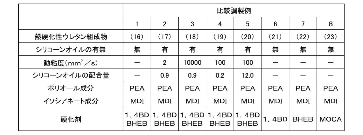
下記表1、2には、熱硬化性ウレタン組成物(1)~(23)の組成について記載した。

2.籾摺りロールの作製及び評価(1)
(実施例1)
本実施例では、形式:統合大60型の籾摺りロールを作製した。
まず、アルミダイキャストにより、図1に示した形状のしん材部を鋳造した。
次に、円筒形の金型内に、上記しん材部の外周面と上記金型の内周面との間隔が全周に渡ってほぼ等間隔になるように上記しん材部を設置した。
その後、上記しん材部の外周面と上記金型の内周面との間隙に、熱硬化性ウレタン組成物(1)を注入し、下記の条件で硬化させ、外径寸法と幅寸法とを切削により調整し、上記しん材部の外周面にゴム層が積層された籾摺りロールを作製した。
(実施例1)
本実施例では、形式:統合大60型の籾摺りロールを作製した。
まず、アルミダイキャストにより、図1に示した形状のしん材部を鋳造した。
次に、円筒形の金型内に、上記しん材部の外周面と上記金型の内周面との間隔が全周に渡ってほぼ等間隔になるように上記しん材部を設置した。
その後、上記しん材部の外周面と上記金型の内周面との間隙に、熱硬化性ウレタン組成物(1)を注入し、下記の条件で硬化させ、外径寸法と幅寸法とを切削により調整し、上記しん材部の外周面にゴム層が積層された籾摺りロールを作製した。
(硬化条件)
注入時の熱硬化性ウレタン組成物(1)の温度を105℃とし、金型温度130℃で60分間硬化させた。
その後、金型から脱型し、110℃、24時間の条件で後硬化を行った。
注入時の熱硬化性ウレタン組成物(1)の温度を105℃とし、金型温度130℃で60分間硬化させた。
その後、金型から脱型し、110℃、24時間の条件で後硬化を行った。
(実施例2~10及び12)
熱硬化性ウレタン組成物(1)に代えて、それぞれ熱硬化性ウレタン組成物(2)~(10)及び(12)のいずれかを使用した以外は実施例1と同様にして籾摺りロールを作製した。
熱硬化性ウレタン組成物(1)に代えて、それぞれ熱硬化性ウレタン組成物(2)~(10)及び(12)のいずれかを使用した以外は実施例1と同様にして籾摺りロールを作製した。
(実施例11)
熱硬化性ウレタン組成物(1)に代えて熱硬化性ウレタン組成物(11)を使用し、下記の条件で硬化させた以外は実施例1と同様にして籾摺りロールを作製した。
(硬化条件)
注入時の熱硬化性ウレタン組成物(11)の温度を105℃とし、金型温度130℃で90分間硬化させた。
その後、金型から脱型し、110℃、24時間の条件で後硬化を行った。
熱硬化性ウレタン組成物(1)に代えて熱硬化性ウレタン組成物(11)を使用し、下記の条件で硬化させた以外は実施例1と同様にして籾摺りロールを作製した。
(硬化条件)
注入時の熱硬化性ウレタン組成物(11)の温度を105℃とし、金型温度130℃で90分間硬化させた。
その後、金型から脱型し、110℃、24時間の条件で後硬化を行った。
(実施例13)
熱硬化性ウレタン組成物(1)に代えて熱硬化性ウレタン組成物(13)を使用し、下記の条件で硬化させた以外は実施例1と同様にして籾摺りロールを作製した。
(硬化条件)
注入時の熱硬化性ウレタン組成物(13)の温度を85℃とし、金型温度130℃で60分間硬化させた。
その後、金型から脱型し、110℃、24時間の条件で後硬化を行った。
熱硬化性ウレタン組成物(1)に代えて熱硬化性ウレタン組成物(13)を使用し、下記の条件で硬化させた以外は実施例1と同様にして籾摺りロールを作製した。
(硬化条件)
注入時の熱硬化性ウレタン組成物(13)の温度を85℃とし、金型温度130℃で60分間硬化させた。
その後、金型から脱型し、110℃、24時間の条件で後硬化を行った。
(実施例14)
熱硬化性ウレタン組成物(1)に代えて熱硬化性ウレタン組成物(14)を使用し、下記の条件で硬化させた以外は実施例1と同様にして籾摺りロールを作製した。
(硬化条件)
注入時の熱硬化性ウレタン組成物(14)の温度を105℃とし、金型温度130℃で60分間硬化させた。
その後、金型から脱型し、110℃、24時間の条件で後硬化を行った。
熱硬化性ウレタン組成物(1)に代えて熱硬化性ウレタン組成物(14)を使用し、下記の条件で硬化させた以外は実施例1と同様にして籾摺りロールを作製した。
(硬化条件)
注入時の熱硬化性ウレタン組成物(14)の温度を105℃とし、金型温度130℃で60分間硬化させた。
その後、金型から脱型し、110℃、24時間の条件で後硬化を行った。
(実施例15)
熱硬化性ウレタン組成物(14)に代えて熱硬化性ウレタン組成物(15)を使用した以外は実施例14と同様にして籾摺りロールを作製した。
熱硬化性ウレタン組成物(14)に代えて熱硬化性ウレタン組成物(15)を使用した以外は実施例14と同様にして籾摺りロールを作製した。
(比較例1~6)
熱硬化性ウレタン組成物(1)に代えて、それぞれ熱硬化性ウレタン組成物(16)~(21)のいずれかを使用した以外は実施例1と同様にして籾摺りロールを作製した。
熱硬化性ウレタン組成物(1)に代えて、それぞれ熱硬化性ウレタン組成物(16)~(21)のいずれかを使用した以外は実施例1と同様にして籾摺りロールを作製した。
(比較例7)
熱硬化性ウレタン組成物(11)に代えて熱硬化性ウレタン組成物(22)を使用した以外は実施例11と同様にして籾摺りロールを作製した。
熱硬化性ウレタン組成物(11)に代えて熱硬化性ウレタン組成物(22)を使用した以外は実施例11と同様にして籾摺りロールを作製した。
(比較例8)
熱硬化性ウレタン組成物(13)に代えて熱硬化性ウレタン組成物(23)を使用した以外は実施例13と同様にして籾摺りロールを作製した。
熱硬化性ウレタン組成物(13)に代えて熱硬化性ウレタン組成物(23)を使用した以外は実施例13と同様にして籾摺りロールを作製した。
(評価)
(1)JIS-A硬さ
実施例1~15及び比較例1~8で作製した籾摺りロールに形成されたゴム層のJIS-A硬さを、JIS K 9124で引用するJIS K 6253に準拠して測定した。但し、測定温度は20℃とし、測定箇所は3か所とした。結果を表3に示した。
(1)JIS-A硬さ
実施例1~15及び比較例1~8で作製した籾摺りロールに形成されたゴム層のJIS-A硬さを、JIS K 9124で引用するJIS K 6253に準拠して測定した。但し、測定温度は20℃とし、測定箇所は3か所とした。結果を表3に示した。
(2)DIN摩耗減量
実施例1~15及び比較例1~8で作製した籾摺りロールに形成されたゴム層のDIN摩耗減量を測定した。
上記DIN摩耗減量の評価は、上記ゴム層と同様の組成の試験片(直径16mm×厚さ6mm)を別途作製し、この試験片を用いて、JIS K 6264に準拠した方法において、試験片の回転:無し(A法)、試験片の付加力:10Nで行った。結果を表3に示した。
実施例1~15及び比較例1~8で作製した籾摺りロールに形成されたゴム層のDIN摩耗減量を測定した。
上記DIN摩耗減量の評価は、上記ゴム層と同様の組成の試験片(直径16mm×厚さ6mm)を別途作製し、この試験片を用いて、JIS K 6264に準拠した方法において、試験片の回転:無し(A法)、試験片の付加力:10Nで行った。結果を表3に示した。
(3)撥水性(水の接触角)
実施例1~15及び比較例1~8で作製した籾摺りロールに形成されたゴム層の水の接触角を下記の方法で測定した。ここで、接触角の測定は、上記(2)のDIN摩耗減量の測定の前後に行った。
即ち、上記(2)で作製した試験片を測定試料とし、DIN摩耗減量を測定する前と測定した後とのそれぞれで、下記の方法により、試験片の表面(摩耗面)の水の接触角を測定した。結果を表3に示した。
上記接触角は、協和界面科学株式会社製の自動接触角計DMe-200を使用し、JIS R 3257「基板ガラス表面のぬれ性試験方法」でのガラス試験片を、上記DIN摩耗減量の測定で使用した試験片に置き換え、静滴法により測定した。
なお、この評価では、接触角が大きいほど表面が疎水性であり、耐水性に優れることを意味する。
実施例1~15及び比較例1~8で作製した籾摺りロールに形成されたゴム層の水の接触角を下記の方法で測定した。ここで、接触角の測定は、上記(2)のDIN摩耗減量の測定の前後に行った。
即ち、上記(2)で作製した試験片を測定試料とし、DIN摩耗減量を測定する前と測定した後とのそれぞれで、下記の方法により、試験片の表面(摩耗面)の水の接触角を測定した。結果を表3に示した。
上記接触角は、協和界面科学株式会社製の自動接触角計DMe-200を使用し、JIS R 3257「基板ガラス表面のぬれ性試験方法」でのガラス試験片を、上記DIN摩耗減量の測定で使用した試験片に置き換え、静滴法により測定した。
なお、この評価では、接触角が大きいほど表面が疎水性であり、耐水性に優れることを意味する。
(4)外観評価(ブリードの有無(1))
実施例1~15及び比較例1~8で作製した籾摺りロールについて、その外観を観察し、表面におけるブリードの発生の有無を評価した。結果を表3に示した。
具体的には、籾摺りロールのゴム層の表面を指触観察し、指先でオイル状成分を拭い取れるか否かで判断した。その結果、オイル成分を拭い取れなかった場合は「ブリードの発生無し」と判断し、オイル成分を拭い取れた場合は「ブリードの発生有り」と判断した。
実施例1~15及び比較例1~8で作製した籾摺りロールについて、その外観を観察し、表面におけるブリードの発生の有無を評価した。結果を表3に示した。
具体的には、籾摺りロールのゴム層の表面を指触観察し、指先でオイル状成分を拭い取れるか否かで判断した。その結果、オイル成分を拭い取れなかった場合は「ブリードの発生無し」と判断し、オイル成分を拭い取れた場合は「ブリードの発生有り」と判断した。
(5)その他(ブリードの有無(2))
上記(2)で作製した試験片を測定試料とし、DIN摩耗減量を測定する前と測定した後とのそれぞれで、上記(4)の評価と同様の手法を用いて、試験片の表面におけるブリードの発生の有無を評価した。
その結果、上記(4)の評価において「ブリードの発生無し」と判断された実施例1~15、並びに、比較例1、3~4及び6~8の試験片では、本評価でも、DIN摩耗減量の測定前及び測定後の両時点において、ブリードの発生はなかった。
一方、比較例2の試験片では、DIN摩耗減量の測定前にはブリードの発生があったものの、DIN摩耗減量に測定後にはブリードの発生は無くなっていた。
また、比較例5の試験片では、DIN摩耗減量の測定前及び測定後の両時点でブリードの発生があった。
上記(2)で作製した試験片を測定試料とし、DIN摩耗減量を測定する前と測定した後とのそれぞれで、上記(4)の評価と同様の手法を用いて、試験片の表面におけるブリードの発生の有無を評価した。
その結果、上記(4)の評価において「ブリードの発生無し」と判断された実施例1~15、並びに、比較例1、3~4及び6~8の試験片では、本評価でも、DIN摩耗減量の測定前及び測定後の両時点において、ブリードの発生はなかった。
一方、比較例2の試験片では、DIN摩耗減量の測定前にはブリードの発生があったものの、DIN摩耗減量に測定後にはブリードの発生は無くなっていた。
また、比較例5の試験片では、DIN摩耗減量の測定前及び測定後の両時点でブリードの発生があった。
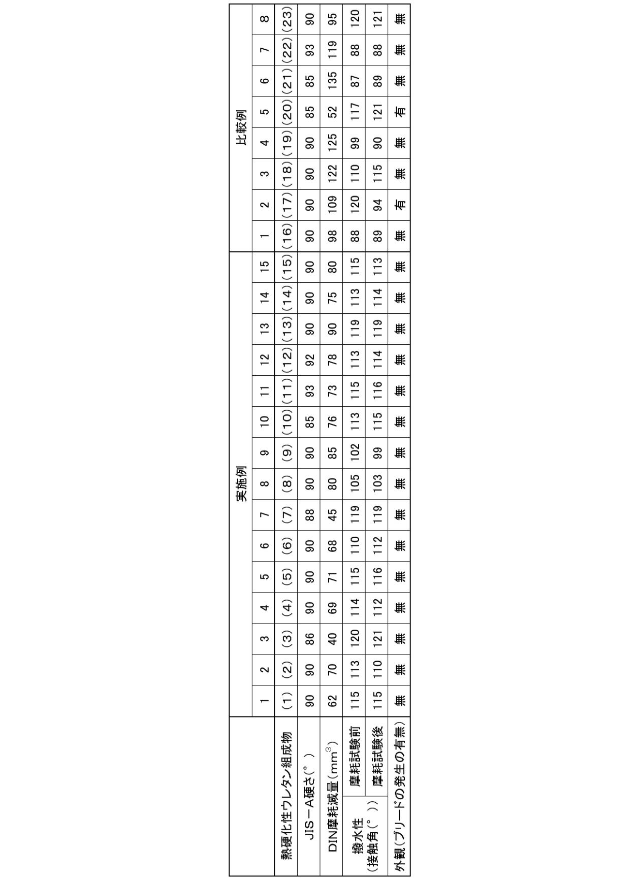
表3に示したように、25℃での動粘度が10~3000mm2/sのシリコーンオイルを、ポリオール成分、イソシアネート成分及び架橋剤の合計量に対して0.3~10.0重量%含有した熱硬化性ウレタン組成物の硬化物からなるゴム層を備えた籾摺りロールは、耐久性(耐摩耗性)及び耐水性に優れることが明らかとなった。また、上記籾摺りロールは、シリコーンオイルがブリードするとの不都合が発生しないことも明らかとなった。
3.籾摺りロールの作製及び評価(2)
(実施例16)
本実施例では、形式:統合100型の籾摺りロールを作製した。
ここでは、形状及び寸法を変更した以外は、実施例1と同様の方法を用いて籾摺りロールを作製した。
(実施例16)
本実施例では、形式:統合100型の籾摺りロールを作製した。
ここでは、形状及び寸法を変更した以外は、実施例1と同様の方法を用いて籾摺りロールを作製した。
作製した籾摺りロールについて、稲美カントリーエレベーター(兵庫南農業協同組合)にて、籾摺り量とゴム層の摩耗量との関係を評価した。
籾摺り機は、株式会社サタケ製、型式:HPS-100HEA(1999年導入)を使用した。
籾米は、銘柄:キヌヒカリ、水分率(玄米基準)14.1~14.3%とした。
処理速度は、約2.5トン/時間とした。
なお、本実施例の脱ぷ率は79%であった。
籾摺り機は、株式会社サタケ製、型式:HPS-100HEA(1999年導入)を使用した。
籾米は、銘柄:キヌヒカリ、水分率(玄米基準)14.1~14.3%とした。
処理速度は、約2.5トン/時間とした。
なお、本実施例の脱ぷ率は79%であった。
本評価では、約1417トンの籾米を処理し、そのときの籾摺りロールのゴム層の摩耗量を計測した。このとき摩耗量は、一対の籾摺りロール(主ロール及び副ロール)のそれぞれの端面に定規を押し当て、残存するゴム層の厚さを計測し、初期のゴム層の厚さ(25mm)との差として算出した。結果を表4に示した。
なお、表4において、主ロール前及び副ロール前の摩耗量とは、籾摺りロールを籾摺り機に取り付けた際に手前に位置する端面で計測した摩耗量をいい、主ロール後及び副ロール後の摩耗量とは、籾摺りロールを籾摺り機に取り付けた際に奥側に位置する端面で計測した摩耗量をいう。
なお、表4において、主ロール前及び副ロール前の摩耗量とは、籾摺りロールを籾摺り機に取り付けた際に手前に位置する端面で計測した摩耗量をいい、主ロール後及び副ロール後の摩耗量とは、籾摺りロールを籾摺り機に取り付けた際に奥側に位置する端面で計測した摩耗量をいう。
更に、上記摩耗量の計測結果に基づいて、籾摺りロールを使用寿命まで(ゴム層の厚さが5mmになるまで)使用した際の予想限界籾摺り量(籾摺り可能な籾米の重量の予想値)を算出した。結果を表4に示した。
なお、予想限界籾摺り量は、上述した方法で計測した4か所の摩耗量の平均値(平均摩耗量)を算出し、平均摩耗量(A)、及び、実際に処理した籾米の重量(B)に基づき、下記計算式(1)より算出した。
予想限界籾摺り量=籾米の重量(B)÷〔平均摩耗量(A)/20〕・・・(1)
なお、予想限界籾摺り量は、上述した方法で計測した4か所の摩耗量の平均値(平均摩耗量)を算出し、平均摩耗量(A)、及び、実際に処理した籾米の重量(B)に基づき、下記計算式(1)より算出した。
予想限界籾摺り量=籾米の重量(B)÷〔平均摩耗量(A)/20〕・・・(1)
(実施例17)
本実施例では、形式:統合100型の籾摺りロールを作製した。
ここでは、形状及び寸法を変更した以外は、実施例12と同様の方法を用いて籾摺りロールを作製した。
本実施例では、形式:統合100型の籾摺りロールを作製した。
ここでは、形状及び寸法を変更した以外は、実施例12と同様の方法を用いて籾摺りロールを作製した。
作製した籾摺りロールについて、豊岡カントリーエレベーター(たじま農業協同組合)にて、籾摺り量とゴム層の摩耗量との関係を評価した。
籾摺り機は、株式会社サタケ社製、型式:HPS-100HEA-K(2004年導入)を使用した。
籾米は、銘柄:コシヒカリ、水分率(玄米基準)14.1~14.5%とした。
処理速度は、約2.8トン/時間とした。
なお、本実施例の脱ぷ率は78%であった。
籾摺り機は、株式会社サタケ社製、型式:HPS-100HEA-K(2004年導入)を使用した。
籾米は、銘柄:コシヒカリ、水分率(玄米基準)14.1~14.5%とした。
処理速度は、約2.8トン/時間とした。
なお、本実施例の脱ぷ率は78%であった。
本評価では、約378トンの籾米を処理し、そのときの籾摺りロールのゴム層の摩耗量を実施例16と同様にして計測した。
更に、上記摩耗量の計測結果に基づいて、予想限界籾摺り量を算出した。
結果を表4に示した。
更に、上記摩耗量の計測結果に基づいて、予想限界籾摺り量を算出した。
結果を表4に示した。
(実施例18)
本実施例では、形式:統合100型の籾摺りロールを作製した。
ここでは、形状及び寸法を変更した以外は、実施例13と同様の方法を用いて籾摺りロールを作製した。
本実施例では、形式:統合100型の籾摺りロールを作製した。
ここでは、形状及び寸法を変更した以外は、実施例13と同様の方法を用いて籾摺りロールを作製した。
作製した籾摺りロールについて、稲美カントリーエレベーター(兵庫南農業協同組合)にて、籾摺り量とゴム層の摩耗量との関係を評価した。
籾摺り機は、サタケ社製、型式:HPS100HEA(1999年導入)を使用した。
籾米は、銘柄:ヒノヒカリ及びキヌヒカリ、水分率(玄米基準):14.3%(ヒノヒカリ)、14.1%(キヌヒカリ)とした。
処理速度は、約2.0トン/時間とした。
なお、本実施例の脱ぷ率は78%であった。
籾摺り機は、サタケ社製、型式:HPS100HEA(1999年導入)を使用した。
籾米は、銘柄:ヒノヒカリ及びキヌヒカリ、水分率(玄米基準):14.3%(ヒノヒカリ)、14.1%(キヌヒカリ)とした。
処理速度は、約2.0トン/時間とした。
なお、本実施例の脱ぷ率は78%であった。
本評価では、約588トンの籾米を処理し、そのときの籾摺りロールのゴム層の摩耗量を実施例16と同様にして計測した。
更に、上記摩耗量の計測結果に基づいて、予想限界籾摺り量を算出した。
結果を表4に示した。
更に、上記摩耗量の計測結果に基づいて、予想限界籾摺り量を算出した。
結果を表4に示した。
(実施例19)
本実施例では、形式:統合100型の籾摺りロールを作製した。
ここでは、形状及び寸法を変更した以外は、実施例14と同様の方法を用いて籾摺りロールを作製した。
本実施例では、形式:統合100型の籾摺りロールを作製した。
ここでは、形状及び寸法を変更した以外は、実施例14と同様の方法を用いて籾摺りロールを作製した。
作製した籾摺りロールについて、日高カントリーエレベーター(たじま農業協同組合)にて、籾摺り量とゴム層の摩耗量との関係を評価した。
籾摺り機は、株式会社サタケ製、統合100型ロール使用もみすり機(1972年導入)を使用した。
籾米は、銘柄:コシヒカリ、水分率(玄米基準):14.2~14.6%とした。
処理速度は、約2.8トン/時間とした。
なお、本実施例の脱ぷ率は78%であった。
籾摺り機は、株式会社サタケ製、統合100型ロール使用もみすり機(1972年導入)を使用した。
籾米は、銘柄:コシヒカリ、水分率(玄米基準):14.2~14.6%とした。
処理速度は、約2.8トン/時間とした。
なお、本実施例の脱ぷ率は78%であった。
本評価では、約175トンの籾米を処理し、そのときの籾摺りロールのゴム層の摩耗量を実施例16と同様にして計測した。
更に、上記摩耗量の計測結果に基づいて、予想限界籾摺り量を算出した。
結果を表4に示した。
更に、上記摩耗量の計測結果に基づいて、予想限界籾摺り量を算出した。
結果を表4に示した。
(実施例20)
本実施例では、形式:統合100型の籾摺りロールを作製した。
ここでは、形状及び寸法を変更した以外は、実施例15と同様の方法を用いて籾摺りロールを作製した。
本実施例では、形式:統合100型の籾摺りロールを作製した。
ここでは、形状及び寸法を変更した以外は、実施例15と同様の方法を用いて籾摺りロールを作製した。
作製した籾摺りロールについて、日高カントリーエレベーター(たじま農業協同組合)にて、籾摺り量とゴム層の摩耗量との関係を評価した。
籾摺り機は、株式会社サタケ製、統合100型ロール使用もみすり機(1972年導入)を使用した。
籾米は、銘柄:コシヒカリ、水分率(玄米基準):14.2~14.6%とした。
処理速度は、約2.8トン/時間とした。
なお、本実施例の脱ぷ率は78%であった。
籾摺り機は、株式会社サタケ製、統合100型ロール使用もみすり機(1972年導入)を使用した。
籾米は、銘柄:コシヒカリ、水分率(玄米基準):14.2~14.6%とした。
処理速度は、約2.8トン/時間とした。
なお、本実施例の脱ぷ率は78%であった。
本評価では、約145トンの籾米を処理し、そのときの籾摺りロールのゴム層の摩耗量を実施例16と同様にして計測した。
更に、上記摩耗量の計測結果に基づいて、予想限界籾摺り量を算出した。
結果を表4に示した。
更に、上記摩耗量の計測結果に基づいて、予想限界籾摺り量を算出した。
結果を表4に示した。
(比較例9)
本比較例では、形式:統合100型の籾摺りロールを作製した。
ここでは、形状及び寸法を変更した以外は、比較例1と同様の方法を用いて籾摺りロールを作製した。
本比較例では、形式:統合100型の籾摺りロールを作製した。
ここでは、形状及び寸法を変更した以外は、比較例1と同様の方法を用いて籾摺りロールを作製した。
作製した籾摺りロールについて、出石カントリーエレベーター(たじま農業協同組合)にて、籾摺り量とゴム層の摩耗量との関係を評価した。
籾摺り機は、株式会社サタケ社製、統合100型ロール使用もみすり機(1972年導入)を使用した。
籾米は、銘柄:コシヒカリ、水分率(玄米基準)14.8~15.0%とした。
処理速度は、約2.5トン/時間とした。
なお、本比較例の脱ぷ率は79%であった。
籾摺り機は、株式会社サタケ社製、統合100型ロール使用もみすり機(1972年導入)を使用した。
籾米は、銘柄:コシヒカリ、水分率(玄米基準)14.8~15.0%とした。
処理速度は、約2.5トン/時間とした。
なお、本比較例の脱ぷ率は79%であった。
本評価では、約142トンの籾米を処理し、そのときの籾摺りロールのゴム層の摩耗量を実施例16と同様にして計測した。
更に、上記摩耗量の計測結果に基づいて、予想限界籾摺り量を算出した。
結果を表4に示した。
更に、上記摩耗量の計測結果に基づいて、予想限界籾摺り量を算出した。
結果を表4に示した。
(比較例10)
本比較例では、形式:統合100型の籾摺りロールを作製した。
ここでは、形状及び寸法を変更した以外は、比較例6と同様の方法を用いて籾摺りロールを作製した。
本比較例では、形式:統合100型の籾摺りロールを作製した。
ここでは、形状及び寸法を変更した以外は、比較例6と同様の方法を用いて籾摺りロールを作製した。
作製した籾摺りロールについて、出石カントリーエレベーター(たじま農業協同組合)にて、籾摺り量とゴム層の摩耗量との関係を評価した。
籾摺り機は、株式会社サタケ社製、統合100型ロール使用もみすり機(1972年導入)を使用した。
籾米は、銘柄:コシヒカリ、水分率(玄米基準)14.8~15.0%とした。
処理速度は、約2.5トン/時間とした。
なお、本比較例の脱ぷ率は79%であった。
籾摺り機は、株式会社サタケ社製、統合100型ロール使用もみすり機(1972年導入)を使用した。
籾米は、銘柄:コシヒカリ、水分率(玄米基準)14.8~15.0%とした。
処理速度は、約2.5トン/時間とした。
なお、本比較例の脱ぷ率は79%であった。
本評価では、約220トンの籾米を処理し、そのときの籾摺りロールのゴム層の摩耗量を実施例16と同様にして計測した。
更に、上記摩耗量の計測結果に基づいて、予想限界籾摺り量を算出した。
結果を表4に示した。
更に、上記摩耗量の計測結果に基づいて、予想限界籾摺り量を算出した。
結果を表4に示した。
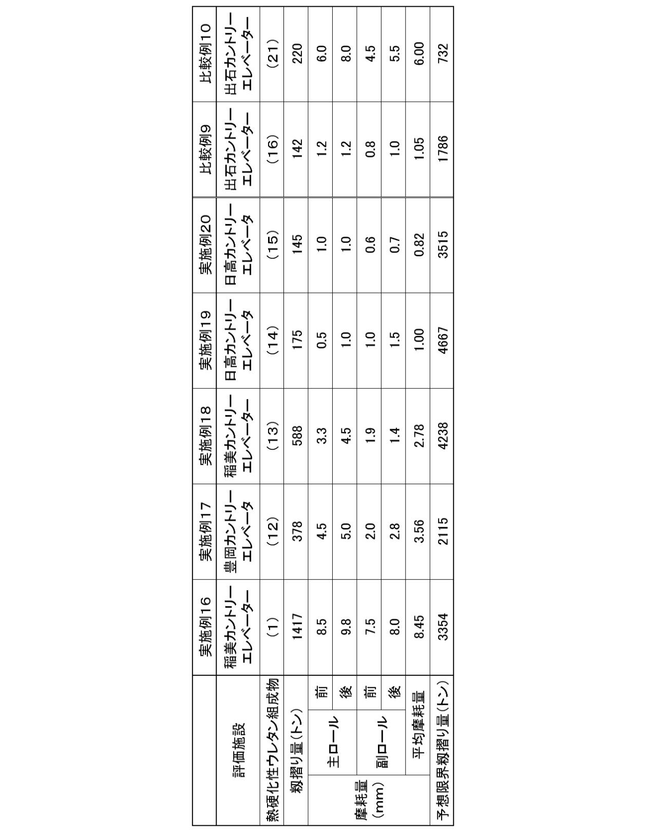
表4に示したように、特定の動粘度のシリコーンオイルを所定量含有する熱硬化性ウレタン組成物の硬化物からなるゴム層を備えた本発明の籾摺りロールは、耐久性に優れるため、長期に渡って使用することができ、籾摺りロールの交換頻度を低減することができることが明らかとなった。
10、10A、10B 籾摺りロール
11 しん材部
11a 取付用フランジ
12 ゴム層
11 しん材部
11a 取付用フランジ
12 ゴム層
Claims (3)
- しん材部と、前記しん材部の外周面に積層されたゴム層とを備えた籾摺りロールであって、
前記ゴム層は、ポリオール成分、イソシアネート成分、架橋剤及びシリコーンオイルを含有する熱硬化性ウレタン組成物の硬化物からなり、
前記イソシアネート成分は、TDI及び/又はMDIであり、
前記シリコーンオイルは、25℃での動粘度が10~3000mm2/sであり、
前記熱硬化性ウレタン組成物における前記シリコーンオイルの含有量は、ポリオール成分、イソシアネート成分及び架橋剤の合計量に対して、0.3~10.0重量%であることを特徴とする籾摺りロール。 - 前記シリコーンオイルは、ジメチルポリシロキサンである請求項1に記載の籾摺りロール。
- 前記架橋剤は、少なくとも1,4-BDである請求項1又は2に記載の籾摺りロール。
Priority Applications (2)
| Application Number | Priority Date | Filing Date | Title |
|---|---|---|---|
| CN201680013692.0A CN107405623B (zh) | 2015-03-09 | 2016-03-02 | 砻谷辊 |
| MYPI2017703235A MY197584A (en) | 2015-03-09 | 2016-03-02 | Rice hulling roll |
Applications Claiming Priority (2)
| Application Number | Priority Date | Filing Date | Title |
|---|---|---|---|
| JP2015-046210 | 2015-03-09 | ||
| JP2015046210A JP5848473B1 (ja) | 2015-03-09 | 2015-03-09 | 籾摺りロール |
Publications (1)
| Publication Number | Publication Date |
|---|---|
| WO2016143633A1 true WO2016143633A1 (ja) | 2016-09-15 |
Family
ID=55176128
Family Applications (1)
| Application Number | Title | Priority Date | Filing Date |
|---|---|---|---|
| PCT/JP2016/056422 Ceased WO2016143633A1 (ja) | 2015-03-09 | 2016-03-02 | 籾摺りロール |
Country Status (4)
| Country | Link |
|---|---|
| JP (1) | JP5848473B1 (ja) |
| CN (1) | CN107405623B (ja) |
| MY (1) | MY197584A (ja) |
| WO (1) | WO2016143633A1 (ja) |
Cited By (1)
| Publication number | Priority date | Publication date | Assignee | Title |
|---|---|---|---|---|
| WO2021025090A1 (ja) * | 2019-08-06 | 2021-02-11 | バンドー化学株式会社 | 籾摺りロール及び籾摺り方法 |
Families Citing this family (2)
| Publication number | Priority date | Publication date | Assignee | Title |
|---|---|---|---|---|
| JP6661413B2 (ja) * | 2016-03-03 | 2020-03-11 | 三井化学株式会社 | 籾摺りロールおよび該籾摺りロールの製造方法 |
| JP6857478B2 (ja) * | 2016-10-05 | 2021-04-14 | バンドー化学株式会社 | 一対の籾摺りロール |
Citations (2)
| Publication number | Priority date | Publication date | Assignee | Title |
|---|---|---|---|---|
| JPS51107948A (ja) * | 1975-03-12 | 1976-09-24 | Bridgestone Tire Co Ltd | |
| JP2011046812A (ja) * | 2009-08-26 | 2011-03-10 | Toyo Tire & Rubber Co Ltd | 潤滑ゴム組成物及び防振ゴム |
Family Cites Families (4)
| Publication number | Priority date | Publication date | Assignee | Title |
|---|---|---|---|---|
| JPS5413378B2 (ja) * | 1974-12-14 | 1979-05-30 | ||
| JP2001029809A (ja) * | 1999-07-27 | 2001-02-06 | Iseki & Co Ltd | 籾摺ロール |
| CN202044972U (zh) * | 2011-03-28 | 2011-11-23 | 来安县安泰聚氨酯制品有限公司 | 一种砻谷胶辊 |
| JP5707522B1 (ja) * | 2014-04-16 | 2015-04-30 | バンドー化学株式会社 | 籾摺りロール |
-
2015
- 2015-03-09 JP JP2015046210A patent/JP5848473B1/ja not_active Expired - Fee Related
-
2016
- 2016-03-02 WO PCT/JP2016/056422 patent/WO2016143633A1/ja not_active Ceased
- 2016-03-02 CN CN201680013692.0A patent/CN107405623B/zh not_active Expired - Fee Related
- 2016-03-02 MY MYPI2017703235A patent/MY197584A/en unknown
Patent Citations (2)
| Publication number | Priority date | Publication date | Assignee | Title |
|---|---|---|---|---|
| JPS51107948A (ja) * | 1975-03-12 | 1976-09-24 | Bridgestone Tire Co Ltd | |
| JP2011046812A (ja) * | 2009-08-26 | 2011-03-10 | Toyo Tire & Rubber Co Ltd | 潤滑ゴム組成物及び防振ゴム |
Cited By (1)
| Publication number | Priority date | Publication date | Assignee | Title |
|---|---|---|---|---|
| WO2021025090A1 (ja) * | 2019-08-06 | 2021-02-11 | バンドー化学株式会社 | 籾摺りロール及び籾摺り方法 |
Also Published As
| Publication number | Publication date |
|---|---|
| CN107405623B (zh) | 2019-05-07 |
| JP2016165672A (ja) | 2016-09-15 |
| MY197584A (en) | 2023-06-26 |
| CN107405623A (zh) | 2017-11-28 |
| JP5848473B1 (ja) | 2016-01-27 |
Similar Documents
| Publication | Publication Date | Title |
|---|---|---|
| JP3576990B2 (ja) | クリーニングブレード、電子写真装置、クリーニングブレードの製造方法 | |
| JP5611386B2 (ja) | 電子写真装置用クリーニングブレード及びその製造方法 | |
| JP5707522B1 (ja) | 籾摺りロール | |
| JP5510950B2 (ja) | クリーニングブレード部材 | |
| JP5797439B2 (ja) | 画像形成装置用クリーニングブレード | |
| JP5848473B1 (ja) | 籾摺りロール | |
| JP2009193055A (ja) | ブレード部材 | |
| JP6857478B2 (ja) | 一対の籾摺りロール | |
| JP2018036363A (ja) | 電子写真機器用クリーニングブレード | |
| JP4811869B2 (ja) | 鳴き防止ロール | |
| WO2016158868A1 (ja) | 熱硬化性ウレタン組成物、硬化物、及び、籾摺りロール | |
| JP2011141449A (ja) | クリーニングブレード | |
| JP6664026B1 (ja) | 籾摺りロール及び籾摺り方法 | |
| JP2008268493A (ja) | 電子写真装置用クリーニングブレード及びその製造方法 | |
| WO2018003364A1 (ja) | 電子写真機器用クリーニングブレード | |
| JP5510962B2 (ja) | ブレード部材 | |
| JP5506606B2 (ja) | 電子写真機器用クリーニングブレード | |
| JP2008268494A (ja) | 電子写真装置用クリーニングブレード及びその製造方法 | |
| JP2008268496A (ja) | 電子写真装置用クリーニングブレード及びその製造方法 | |
| JP4416086B2 (ja) | 鳴き防止ロール | |
| JP6530293B2 (ja) | クリーニングブレード | |
| JP2021041351A (ja) | 籾摺りロール | |
| KR19990039200A (ko) | 내마모성이 우수한 우레탄 고무용 우레탄 혼합 수지조성물 |
Legal Events
| Date | Code | Title | Description |
|---|---|---|---|
| 121 | Ep: the epo has been informed by wipo that ep was designated in this application |
Ref document number: 16761603 Country of ref document: EP Kind code of ref document: A1 |
|
| NENP | Non-entry into the national phase |
Ref country code: DE |
|
| 122 | Ep: pct application non-entry in european phase |
Ref document number: 16761603 Country of ref document: EP Kind code of ref document: A1 |