WO2016140288A1 - 液晶配向剤、液晶配向膜及び液晶表示素子 - Google Patents
液晶配向剤、液晶配向膜及び液晶表示素子 Download PDFInfo
- Publication number
- WO2016140288A1 WO2016140288A1 PCT/JP2016/056506 JP2016056506W WO2016140288A1 WO 2016140288 A1 WO2016140288 A1 WO 2016140288A1 JP 2016056506 W JP2016056506 W JP 2016056506W WO 2016140288 A1 WO2016140288 A1 WO 2016140288A1
- Authority
- WO
- WIPO (PCT)
- Prior art keywords
- liquid crystal
- aligning agent
- group
- crystal aligning
- component
- Prior art date
- Legal status (The legal status is an assumption and is not a legal conclusion. Google has not performed a legal analysis and makes no representation as to the accuracy of the status listed.)
- Ceased
Links
- 0 *c(cc1)ccc1-c1ccc(*c(c(N)c2)ccc2N)cc1 Chemical compound *c(cc1)ccc1-c1ccc(*c(c(N)c2)ccc2N)cc1 0.000 description 3
- SQNRVNZOHQGXJR-UHFFFAOYSA-N C=C(CC(CCc(cc1)ccc1-c1ccc(C(CC2=C)OC2=O)cc1)O1)C1=O Chemical compound C=C(CC(CCc(cc1)ccc1-c1ccc(C(CC2=C)OC2=O)cc1)O1)C1=O SQNRVNZOHQGXJR-UHFFFAOYSA-N 0.000 description 1
- KLWHSYHBGSGRJE-UHFFFAOYSA-N CC(C)(C(C1C=CC(OCCOC(C(C2)=CC(N)=CC2N)=O)=CC1)=O)O Chemical compound CC(C)(C(C1C=CC(OCCOC(C(C2)=CC(N)=CC2N)=O)=CC1)=O)O KLWHSYHBGSGRJE-UHFFFAOYSA-N 0.000 description 1
- UVZQYEYSADLTDJ-UHFFFAOYSA-N CC(C)(C(c(cc1)ccc1OCCOC1C=CC(N)=CC1N)=O)OC Chemical compound CC(C)(C(c(cc1)ccc1OCCOC1C=CC(N)=CC1N)=O)OC UVZQYEYSADLTDJ-UHFFFAOYSA-N 0.000 description 1
- ZQERRTPXURFNBC-UHFFFAOYSA-N CC(C)(C(c(cc1)ccc1OCCOc(c(N)c1)ccc1N)=O)O Chemical compound CC(C)(C(c(cc1)ccc1OCCOc(c(N)c1)ccc1N)=O)O ZQERRTPXURFNBC-UHFFFAOYSA-N 0.000 description 1
- QNODIIQQMGDSEF-UHFFFAOYSA-N OC1(CCCCC1)C(c1ccccc1)=O Chemical compound OC1(CCCCC1)C(c1ccccc1)=O QNODIIQQMGDSEF-UHFFFAOYSA-N 0.000 description 1
Classifications
-
- C—CHEMISTRY; METALLURGY
- C09—DYES; PAINTS; POLISHES; NATURAL RESINS; ADHESIVES; COMPOSITIONS NOT OTHERWISE PROVIDED FOR; APPLICATIONS OF MATERIALS NOT OTHERWISE PROVIDED FOR
- C09K—MATERIALS FOR MISCELLANEOUS APPLICATIONS, NOT PROVIDED FOR ELSEWHERE
- C09K11/00—Luminescent materials, e.g. electroluminescent or chemiluminescent
- C09K11/08—Luminescent materials, e.g. electroluminescent or chemiluminescent containing inorganic luminescent materials
- C09K11/56—Luminescent materials, e.g. electroluminescent or chemiluminescent containing inorganic luminescent materials containing sulfur
-
- C—CHEMISTRY; METALLURGY
- C08—ORGANIC MACROMOLECULAR COMPOUNDS; THEIR PREPARATION OR CHEMICAL WORKING-UP; COMPOSITIONS BASED THEREON
- C08G—MACROMOLECULAR COMPOUNDS OBTAINED OTHERWISE THAN BY REACTIONS ONLY INVOLVING UNSATURATED CARBON-TO-CARBON BONDS
- C08G73/00—Macromolecular compounds obtained by reactions forming a linkage containing nitrogen with or without oxygen or carbon in the main chain of the macromolecule, not provided for in groups C08G12/00 - C08G71/00
- C08G73/06—Polycondensates having nitrogen-containing heterocyclic rings in the main chain of the macromolecule
- C08G73/10—Polyimides; Polyester-imides; Polyamide-imides; Polyamide acids or similar polyimide precursors
-
- C—CHEMISTRY; METALLURGY
- C08—ORGANIC MACROMOLECULAR COMPOUNDS; THEIR PREPARATION OR CHEMICAL WORKING-UP; COMPOSITIONS BASED THEREON
- C08G—MACROMOLECULAR COMPOUNDS OBTAINED OTHERWISE THAN BY REACTIONS ONLY INVOLVING UNSATURATED CARBON-TO-CARBON BONDS
- C08G73/00—Macromolecular compounds obtained by reactions forming a linkage containing nitrogen with or without oxygen or carbon in the main chain of the macromolecule, not provided for in groups C08G12/00 - C08G71/00
- C08G73/06—Polycondensates having nitrogen-containing heterocyclic rings in the main chain of the macromolecule
- C08G73/10—Polyimides; Polyester-imides; Polyamide-imides; Polyamide acids or similar polyimide precursors
- C08G73/1003—Preparatory processes
- C08G73/1007—Preparatory processes from tetracarboxylic acids or derivatives and diamines
- C08G73/1025—Preparatory processes from tetracarboxylic acids or derivatives and diamines polymerised by radiations
-
- C—CHEMISTRY; METALLURGY
- C08—ORGANIC MACROMOLECULAR COMPOUNDS; THEIR PREPARATION OR CHEMICAL WORKING-UP; COMPOSITIONS BASED THEREON
- C08L—COMPOSITIONS OF MACROMOLECULAR COMPOUNDS
- C08L79/00—Compositions of macromolecular compounds obtained by reactions forming in the main chain of the macromolecule a linkage containing nitrogen with or without oxygen or carbon only, not provided for in groups C08L61/00 - C08L77/00
- C08L79/04—Polycondensates having nitrogen-containing heterocyclic rings in the main chain; Polyhydrazides; Polyamide acids or similar polyimide precursors
- C08L79/08—Polyimides; Polyester-imides; Polyamide-imides; Polyamide acids or similar polyimide precursors
-
- G—PHYSICS
- G02—OPTICS
- G02F—OPTICAL DEVICES OR ARRANGEMENTS FOR THE CONTROL OF LIGHT BY MODIFICATION OF THE OPTICAL PROPERTIES OF THE MEDIA OF THE ELEMENTS INVOLVED THEREIN; NON-LINEAR OPTICS; FREQUENCY-CHANGING OF LIGHT; OPTICAL LOGIC ELEMENTS; OPTICAL ANALOGUE/DIGITAL CONVERTERS
- G02F1/00—Devices or arrangements for the control of the intensity, colour, phase, polarisation or direction of light arriving from an independent light source, e.g. switching, gating or modulating; Non-linear optics
- G02F1/01—Devices or arrangements for the control of the intensity, colour, phase, polarisation or direction of light arriving from an independent light source, e.g. switching, gating or modulating; Non-linear optics for the control of the intensity, phase, polarisation or colour
- G02F1/13—Devices or arrangements for the control of the intensity, colour, phase, polarisation or direction of light arriving from an independent light source, e.g. switching, gating or modulating; Non-linear optics for the control of the intensity, phase, polarisation or colour based on liquid crystals, e.g. single liquid crystal display cells
- G02F1/133—Constructional arrangements; Operation of liquid crystal cells; Circuit arrangements
- G02F1/1333—Constructional arrangements; Manufacturing methods
- G02F1/1337—Surface-induced orientation of the liquid crystal molecules, e.g. by alignment layers
-
- G—PHYSICS
- G02—OPTICS
- G02F—OPTICAL DEVICES OR ARRANGEMENTS FOR THE CONTROL OF LIGHT BY MODIFICATION OF THE OPTICAL PROPERTIES OF THE MEDIA OF THE ELEMENTS INVOLVED THEREIN; NON-LINEAR OPTICS; FREQUENCY-CHANGING OF LIGHT; OPTICAL LOGIC ELEMENTS; OPTICAL ANALOGUE/DIGITAL CONVERTERS
- G02F1/00—Devices or arrangements for the control of the intensity, colour, phase, polarisation or direction of light arriving from an independent light source, e.g. switching, gating or modulating; Non-linear optics
- G02F1/01—Devices or arrangements for the control of the intensity, colour, phase, polarisation or direction of light arriving from an independent light source, e.g. switching, gating or modulating; Non-linear optics for the control of the intensity, phase, polarisation or colour
- G02F1/13—Devices or arrangements for the control of the intensity, colour, phase, polarisation or direction of light arriving from an independent light source, e.g. switching, gating or modulating; Non-linear optics for the control of the intensity, phase, polarisation or colour based on liquid crystals, e.g. single liquid crystal display cells
- G02F1/133—Constructional arrangements; Operation of liquid crystal cells; Circuit arrangements
- G02F1/1333—Constructional arrangements; Manufacturing methods
- G02F1/1337—Surface-induced orientation of the liquid crystal molecules, e.g. by alignment layers
- G02F1/133711—Surface-induced orientation of the liquid crystal molecules, e.g. by alignment layers by organic films, e.g. polymeric films
- G02F1/133723—Polyimide, polyamide-imide
Definitions
- the present invention relates to a liquid crystal aligning agent, a liquid crystal alignment film, and a liquid crystal display element that can be used for a liquid crystal display element of a vertical alignment type manufactured by irradiating ultraviolet rays with voltage applied to liquid crystal molecules.
- a liquid crystal display element of a method in which liquid crystal molecules aligned perpendicular to the substrate respond by an electric field also referred to as a vertical alignment (VA) method
- VA vertical alignment
- a photopolymerizable compound is previously added to the liquid crystal composition, and a polyimide-based vertical alignment film is used, and ultraviolet rays are applied while applying a voltage to the liquid crystal cell. Therefore, a technique for increasing the response speed of liquid crystal (PSA (Polymer Sustained Alignment) type element, for example, see Patent Document 1 and Non-Patent Document 1) is known.
- PSA Polymer Sustained Alignment
- the direction in which the liquid crystal molecules incline in response to an electric field is usually controlled by protrusions provided on the substrate or slits provided on the display electrode, but photopolymerization is performed in the liquid crystal composition.
- photopolymerization is performed in the liquid crystal composition.
- the polymerizable compound reacts efficiently and exhibits the ability to fix alignment by irradiation with ultraviolet rays having a long wavelength without decomposition of components in the liquid crystal. Furthermore, it is necessary that unreacted polymerizable compound does not remain after ultraviolet irradiation and does not adversely affect the reliability of the liquid crystal display element.
- An object of the present invention is to solve the above-mentioned problems of the prior art, and to efficiently react a polymerizable compound even when irradiated with ultraviolet rays of a long wavelength, thereby improving the response speed of a vertical alignment type liquid crystal display device. Furthermore, it is to provide a liquid crystal aligning agent, a liquid crystal alignment film, a liquid crystal display element, and a method for manufacturing the liquid crystal display element, which can improve the electric characteristics of the obtained liquid crystal display element, particularly the direct current charge storage characteristics. .
- the liquid crystal aligning agent characterized by containing the following (A) component, (B) component, and an organic solvent.
- R 1 and R 2 are each independently an alkyl group or alkoxy group having 1 to 10 carbon atoms, and T 1 and T 2 are each independently a single bond or —O—, —COO—, —OCO—.
- alkylene group —CH 2 — or —CF 2 — may be optionally replaced with —CH ⁇ CH—, and when any of the following groups is not adjacent to each other, these groups are replaced with these groups: -O-, -COO-, -OCO-, -NHCO-, -CONH-, -NH-, a divalent carbocycle, a divalent heterocycle, and Q is a structure selected from the following: Represents.
- R is a hydrogen atom or an alkyl group having 1 to 4 carbon atoms.
- Component (B) a polyimide precursor obtained by using a diamine component containing at least one diamine selected from the following formulas (B-1) to (B-5) as a raw material, and imidating the polyimide precursor
- Y 1 is a monovalent organic group having a secondary amine, tertiary amine or heterocyclic structure
- Y 2 is a divalent organic group having a secondary amine, tertiary amine or heterocyclic structure.
- N and m are 0 or 1
- X and y are a single bond, carbonyl, ester, phenylene and sulfonyl group.
- a liquid crystal alignment film obtained by applying the liquid crystal aligning agent according to 2.1 to a substrate and baking it.
- a liquid crystal layer is provided by contacting a liquid crystal alignment film obtained by applying the liquid crystal aligning agent described in 3.1 to a substrate and baking it, and applying a voltage to the liquid crystal layer to provide a liquid crystal cell.
- a liquid crystal display element is provided by contacting a liquid crystal alignment film obtained by applying the liquid crystal aligning agent described in 3.1 to a substrate and baking it, and applying a voltage to the liquid crystal layer to provide a liquid crystal cell.
- a liquid crystal layer is provided by contacting a liquid crystal alignment film obtained by applying and baking the liquid crystal alignment agent described in 4.1 to a substrate, and applying a voltage to the liquid crystal layer to produce a liquid crystal cell.
- a method of manufacturing a liquid crystal display element is provided by contacting a liquid crystal alignment film obtained by applying and baking the liquid crystal alignment agent described in 4.1 to a substrate, and applying a voltage to the liquid crystal layer to produce a liquid crystal cell.
- a vertical alignment type liquid crystal display device that can increase the response speed of liquid crystal even when irradiated with ultraviolet rays of a long wavelength and has little DC charge accumulation.
- the liquid crystal aligning agent of this invention contains the following (A) component, (B) component, and an organic solvent.
- Component (A) a polyimide precursor having a side chain for vertically aligning liquid crystals, and a side chain having a site that generates radicals by ultraviolet irradiation represented by the following formula (I), and this polyimide precursor At least one polymer selected from polyimides obtained by imidization.
- Component (B) selected from a polyimide precursor obtained by using at least one diamine selected from the following formulas (B-1) to (B-5) as a raw material, and a polyimide obtained by imidizing this polyimide precursor Or a polyimide precursor obtained by using at least one tetracarboxylic dianhydride selected from the following formulas (3) and (4) as a raw material, and obtained by imidizing this polyimide precursor A polymer selected from polyimides.
- the liquid crystal alignment film is a solution for forming a liquid crystal alignment film, and the liquid crystal alignment film is a film for aligning liquid crystals in a predetermined direction.
- the liquid crystal aligning agent of the present invention includes a polyimide precursor having a side chain for vertically aligning a liquid crystal, and a side chain having a site that generates a radical by ultraviolet irradiation represented by the above formula (1), and the polyimide. It is at least one polymer selected from polyimides obtained by imidizing a precursor.
- the polyimide precursor represents a polyamic acid and a polyamic acid ester.
- the component (A) contained in the liquid crystal aligning agent of the present invention has a site where a radical is generated by ultraviolet irradiation as a side chain.
- a site where radicals are generated by ultraviolet irradiation can be represented by the following formula (I).
- Ar to which carbonyl is bonded is involved in the absorption wavelength of ultraviolet rays. Therefore, when the wavelength is increased, a structure having a long conjugate length such as naphthylene or biphenylene is preferable.
- Ar may be substituted with a substituent, and the substituent is preferably an electron-donating organic group such as an alkyl group, a hydroxyl group, an alkoxy group, and an amino group.
- Ar has a structure such as naphthylene or biphenylene
- the solubility becomes poor and the difficulty of synthesis increases.
- the ultraviolet wavelength is in the range of 250 nm to 380 nm, a phenyl group is most preferable because sufficient characteristics can be obtained even with a phenyl group.
- R 1 and R 2 are each independently an alkyl group having 1 to 10 carbon atoms, an alkoxy group, a benzyl group, or a phenethyl group. In the case of an alkyl group or an alkoxy group, R 1 and R 2 are May be formed.
- Q is preferably an electron-donating organic group, and the following is preferable.
- R represents a hydrogen atom or an alkyl group having 1 to 4 carbon atoms
- R 3 represents —CH 2 —, —NR—, —O—, or —S—).
- R is preferably an alkyl group having 1 to 4 carbon atoms for the purpose of increasing the surface abundance of the component (A) after coating. This is because, when Q is alkyl, the polarity becomes low and the surface easily moves to the surface. Further, in view of the difficulty of synthesis, etc., 1 to 2 is more preferable, and 1 is most preferable.
- the side chain structure of the formula (I) is used. It is preferable from the viewpoint of easy handling of the raw materials and easy synthesis of the polymer.
- the site where radicals are generated by ultraviolet irradiation in the above formula (I) is preferably as follows.
- (b), (c) or (d) is preferable from the viewpoint of the reliability of the obtained liquid crystal display element, and (d) is more preferable from the viewpoint of the surface layer abundance ratio of the radical generation site on the surface of the liquid crystal alignment film. .
- T 1 and T 2 are each independently a single bond, —O—, —S—, —COO—, —OCO—, —NHCO—, —CONH—, —NH—, —CH 2 O—, —N (CH 3 ) —, —CON (CH 3 ) —, or —N (CH 3 ) CO—.
- S is a single bond or an alkylene group having 1 to 20 carbon atoms which may be substituted with a fluorine atom (provided that —CH 2 — or —CF 2 — of the alkylene group is optionally substituted with —CH ⁇ CH—). If any of the following groups are not adjacent to each other, these groups may be substituted; —O—, —COO—, —OCO—, —NHCO—, —CONH—, — NH—, a divalent carbocyclic ring or a heterocyclic ring. In particular, T 2 is most preferably —O— in terms of synthesis difficulty.
- S is preferably an alkylene group having 2 to 10 carbon atoms, more preferably 4 to 8 carbon atoms, from the viewpoint of synthesis difficulty or solubility.
- the polymer contained in the liquid crystal aligning agent of the present invention preferably has a side chain for vertically aligning the liquid crystal in addition to the side chain represented by the above formula (I).
- the side chain for vertically aligning the liquid crystal is represented by the following formula [II-1] or [II-2].
- X 1 , X 2 , X 3 , X 4 , X 5 , and n in the formula [II-1] are as defined above.
- X 1 is a single bond, — (CH 2 ) a — (a is an integer of 1 to 15), —O—, —CH 2 O, from the viewpoint of availability of raw materials and ease of synthesis.
- — Or —COO— is preferable, and more preferable is a single bond, — (CH 2 ) a — (a is an integer of 1 to 10), —O—, —CH 2 O— or —COO—.
- X 2 is preferably a single bond or (CH 2 ) b — (b is an integer of 1 to 10).
- X 3 is a single bond, — (CH 2 ) c — (c is an integer of 1 to 15), —O—, —CH 2 O—, or —COO—, among these, from the viewpoint of ease of synthesis. And more preferably a single bond, — (CH 2 ) c — (c is an integer of 1 to 10), —O—, —CH 2 O— or —COO—.
- X 4 is preferably an organic group having 17 to 51 carbon atoms having a benzene ring, a cyclohexane ring or a steroid skeleton from the viewpoint of ease of synthesis.
- X 5 is preferably a benzene ring or a cyclohexane ring.
- n is preferably 0 to 3 and more preferably 0 to 2 in view of availability of raw materials and ease of synthesis.
- X 6 is preferably an alkyl group having 1 to 18 carbon atoms, a fluorine-containing alkyl group having 1 to 10 carbon atoms, an alkoxyl group having 1 to 18 carbon atoms, or a fluorine-containing alkoxyl group having 1 to 10 carbon atoms. More preferably, it is an alkyl group having 1 to 12 carbon atoms or an alkoxyl group having 1 to 12 carbon atoms. Particularly preferred is an alkyl group having 1 to 9 carbon atoms or an alkoxyl group having 1 to 9 carbon atoms.
- the organic group having 17 to 51 carbon atoms having a steroid skeleton in the present invention has 12 to 20 carbon atoms having a steroid skeleton.
- An organic group having 12 to 25 carbon atoms having a steroid skeleton is to be read as an organic group having 17 to 51 carbon atoms having a steroid skeleton.
- (2-25) to (2-96), (2-145) to (2-168), (2-217) to (2-240), (2-268) to (2-315) , (2-364) to (2-387), (2-436) to (2-483), or (2-603) to (2-615) are preferred.
- Particularly preferred combinations are (2-49) to (2-96), (2-145) to (2-168), (2-217) to (2-240), (2-603) to (2- 606), (2-607) to (2-609), (2-611), (2-612) or (2-624).
- X 7 and X 8 are as defined above.
- X 7 is preferably a single bond, —O—, —CH 2 O—, —CONH—, —CON (CH 3 ) — or —COO—, and more preferably a single bond, —O—, — CONH- or -COO-.
- X 8 is preferably an alkyl group having 8 to 18 carbon atoms.
- the side chain for vertically aligning the liquid crystal it is preferable to use a structure represented by the formula [II-1] from the viewpoint that a high and stable vertical alignment of the liquid crystal can be obtained.
- the ability of a polymer having side chains for vertically aligning liquid crystals to align liquid crystals vertically varies depending on the structure of the side chains for vertically aligning liquid crystals, but in general, the side chains for vertically aligning liquid crystals. As the amount increases, the ability to align the liquid crystal vertically increases, and as the amount decreases, it decreases. Moreover, when it has a cyclic structure, compared with what does not have a cyclic structure, there exists a tendency for the capability to orientate a liquid crystal vertically.
- the component (A) contained in the liquid crystal aligning agent of the present invention may have a photoreactive side chain in addition to the side chain represented by the formula (I).
- the photoreactive side chain has a functional group (hereinafter also referred to as a photoreactive group) that can react by irradiation with light such as ultraviolet rays (UV) to form a covalent bond.
- the photoreactive side chain may be directly bonded to the main chain of the polymer, or may be bonded via a linking group.
- the photoreactive side chain is represented, for example, by the following formula (III).
- R 8 , R 9 and R 10 are as defined above.
- R 8 is preferably a single bond, —O—, —COO—, —NHCO—, or —CONH—.
- R 9 can be formed by a common organic synthetic method, but from the viewpoint of ease of synthesis, a single bond or an alkylene group having 1 to 12 carbon atoms is preferable.
- divalent carbocycle or heterocycle for replacing any —CH 2 — in R 9 include the following.
- R 10 is preferably a methacryl group, an acryl group, a vinyl group or a styryl group from the viewpoint of photoreactivity.
- the amount of the photoreactive side chain is preferably within a range in which the response speed of the liquid crystal can be increased by reacting with ultraviolet irradiation to form a covalent bond. In order to further increase the response speed of the liquid crystal It is preferable that it is as many as possible within a range that does not affect other characteristics.
- the diamine (hereinafter also referred to as “specific diamine”) used in the production of the polymer forming the liquid crystal aligning agent of the present invention has a side chain as a side chain where a radical is generated by irradiation with ultraviolet rays.
- the diaminobenzene in the formula (1) may have any structure of o-phenylenediamine, m-phenylenediamine, or p-phenylenediamine. However, in terms of reactivity with acid dianhydride, m-phenylenediamine, or p-Phenylenediamine is preferred.
- n is an integer of 2 to 8.
- the specific diamine is a dinitro compound through each step, or a mononitro compound having an amino group with a protective group that can be removed in the reduction process, or a nitro group in a commonly used reduction reaction. Can be obtained by converting to an amino group or deprotecting the protecting group.
- n is an integer of 2 to 8.
- the base to be used is not particularly limited, inorganic bases such as potassium carbonate, sodium carbonate and cesium carbonate, and organic bases such as pyridine, dimethylaminopyridine, trimethylamine, triethylamine and tributylamine are preferable.
- the method for reducing the dinitro compound, which is a diamine precursor is not particularly limited. Usually, palladium carbon, platinum oxide, Raney nickel, platinum carbon, rhodium-alumina, platinum sulfide carbon, etc. are used as a catalyst, ethyl acetate, toluene, tetrahydrofuran. There is a method in which reduction is carried out with hydrogen gas, hydrazine, hydrogen chloride or the like in a solvent such as dioxane or alcohol. You may use an autoclave etc. as needed.
- an unsaturated bond site is included in the structure, if palladium carbon or platinum carbon is used, the unsaturated bond site may be reduced and become a saturated bond. Reduction conditions using a transition metal such as tin chloride, poisoned palladium carbon or platinum carbon, platinum carbon doped with iron or the like as a catalyst are preferable.
- the diamine of the present invention can be obtained by deprotecting the diaminobenzene derivative protected with a benzyl group or the like in the same reduction step.
- the specific diamine is preferably 10 to 80 mol%, more preferably 20 to 60 mol%, particularly preferably 30 to 50 mol% of the diamine component used for the synthesis of the polyamic acid.
- ⁇ Diamines with side chains that align liquid crystals vertically> it is preferable to use a diamine having a specific side chain structure as a part of the diamine component.
- a diamine represented by the following formula [2] also referred to as a specific side chain diamine compound.
- X represents a structure represented by the formula [II-1] or [II-2], n represents an integer of 1 to 4, and 1 is particularly preferable.
- a diamine represented by the following formula [2-1] from the viewpoint that a high and stable liquid crystal vertical alignment can be obtained.
- X 1 , X 2 , X 3 , X 4 , X 5 , and n in the above formula [2-1] are the same as defined in each of the above formula [II-1], and Preferable ones are also the same as defined above in Formula [II-1].
- m is an integer of 1 to 4. Preferably, it is an integer of 1.
- Specific examples of the specific side chain diamine include structures represented by the following formulas [2a-1] to [2a-31].
- R 1 represents —O—, —OCH 2 —, —CH 2 O—, —COOCH 2 — or —CH 2 OCO—
- R 2 represents a linear or branched alkyl group having 1 to 22 carbon atoms, A linear or branched alkoxyl group having 1 to 22 carbon atoms, a linear or branched, fluorine-containing alkyl group or fluorine-containing alkoxyl group having 1 to 22 carbon atoms.
- R 3 represents —COO—, —OCO—, —CONH—, —NHCO—, —COOCH 2 —, —CH 2 OCO—, —CH 2 O—, —OCH 2 — or —CH 2 —
- R 4 is a linear or branched alkyl group having 1 to 22 carbon atoms, a linear or branched alkoxyl group having 1 to 22 carbon atoms, a linear or branched alkyl group having 1 to 22 carbon atoms, or a fluorine-containing alkyl group. Group or fluorine-containing alkoxyl group).
- R 5 is —COO—, —OCO—, —CONH—, —NHCO—, —COOCH 2 —, —CH 2 OCO—, —CH 2 O—, —OCH 2 —, —CH 2 —, —O — Or —NH—, wherein R 6 is a fluorine group, a cyano group, a trifluoromethane group, a nitro group, an azo group, a formyl group, an acetyl group, an acetoxy group or a hydroxyl group.
- R 7 is a linear or branched alkyl group having 3 to 12 carbon atoms, and the cis-trans isomerism of 1,4-cyclohexylene is a trans isomer).
- R 8 is a linear or branched alkyl group having 3 to 12 carbon atoms, and the cis-trans isomerism of 1,4-cyclohexylene is a trans isomer).
- a 4 is a linear or branched alkyl group having 3 to 20 carbon atoms which may be substituted with a fluorine atom, and A 3 is a 1,4-cyclohexylene group or a 1,4-phenylene group.
- a 2 is an oxygen atom or COO- * (where a bond with “*” is bonded to A 3 ), and A 1 is an oxygen atom or COO— * (where “*” is a bond)
- the hand binds to (CH 2 ) a 2 ).
- a 1 is an integer of 0 or 1
- a 2 is an integer of 2 to 10
- a 3 is an integer of 0 or 1.
- examples of the diamine having the specific side chain structure represented by the formula [II-2] include diamines represented by the following formulas [2b-1] to [2b-10].
- a 1 represents an alkyl group having 1 to 22 carbon atoms or a fluorine-containing alkyl group).
- a 1 represents —COO—, —OCO—, —CONH—, —NHCO—, —CH 2 —, —O—, —CO— or —NH.
- a 2 represents a linear or branched alkyl group having 1 to 22 carbon atoms or a linear or branched fluorine-containing alkyl group having 1 to 22 carbon atoms.
- the above diamines can be used alone or in combination of two or more depending on the properties such as liquid crystal orientation, pretilt angle, voltage holding property, and accumulated charge when the liquid crystal alignment film is used.
- the diamine having a side chain for vertically aligning the liquid crystal is preferably used in an amount of 5 to 50 mol% of the diamine component used for the synthesis of the polyamic acid, more preferably 10 to 40 mol% of the diamine component, and particularly preferably. Is from 15 to 30 mol%.
- Use of a diamine having a side chain that orients the liquid crystal vertically is particularly excellent in terms of improving the response speed and aligning and fixing the liquid crystal.
- Examples of the diamine having a photoreactive side chain include a diamine having a side chain represented by formula (3), and specifically, a diamine represented by the following general formula (3). However, it is not limited to this.
- the bonding position of the two amino groups (—NH 2 ) in the formula (3) is not limited. Specifically, with respect to the linking group of the side chain, 2, 3 position, 2, 4 position, 2, 5 position, 2, 6 position, 3, 4 position on the benzene ring, 3, 4 position, 5 positions. Among these, from the viewpoint of reactivity when synthesizing a polyamic acid, positions 2, 4, 2, 5, or 3, 5 are preferable. Considering the ease in synthesizing the diamine, the positions 2, 4 or 3, 5 are more preferable.
- diamine having a photoreactive side chain examples include the following.
- X 9 and X 10 are each independently a single bond, —O—, —COO—, —NHCO—, or —NH—, a linking group, and Y is a carbon atom which may be substituted with a fluorine atom. Represents an alkylene group of ⁇ 20.
- examples of the diamine having a photoreactive side chain include a diamine having a group causing a photodimerization reaction and a group causing a photopolymerization reaction represented by the following formula in the side chain.
- Y 1 represents —CH 2 —, —O—, —CONH—, —NHCO—, —COO—, —OCO—, —NH—, or —CO—.
- Y 2 is an alkylene group having 1 to 30 carbon atoms, a divalent carbocycle or a heterocycle, and one or more hydrogen atoms of the alkylene group, divalent carbocycle or heterocycle are fluorine atoms or organic It may be substituted with a group.
- Y 2 when the following groups are not adjacent to each other, —CH 2 — may be substituted with these groups; —O—, —NHCO—, —CONH—, —COO—, —OCO—, —NH—, —NHCONH—, —CO—.
- Y 3 represents —CH 2 —, —O—, —CONH—, —NHCO—, —COO—, —OCO—, —NH—, —CO—, or a single bond.
- Y 4 represents a cinnamoyl group.
- Y 5 is a single bond, an alkylene group having 1 to 30 carbon atoms, a divalent carbocycle or a heterocycle, and one or more hydrogen atoms of the alkylene group, divalent carbocycle or heterocycle are fluorine atoms Alternatively, it may be substituted with an organic group.
- —CH 2 — may be substituted with these groups; —O—, —NHCO—, —CONH—, —COO—, —OCO—, —NH—, —NHCONH—, —CO—.
- Y 6 represents a photopolymerizable group which is an acrylic group or a methacryl group.
- diamine having a group causing a photodimerization reaction and a group causing a photopolymerization reaction in the side chain include the following, but are not limited thereto.
- One or two diamines may be used depending on the liquid crystal alignment properties, pretilt angle, voltage holding characteristics, characteristics such as stored charge, response speed of liquid crystal when used as a liquid crystal display element.
- the above can be mixed and used.
- the diamine having a photoreactive side chain is preferably used in an amount of 10 to 70 mol%, more preferably 20 to 60 mol%, particularly preferably 30 to 50 mol% of the diamine component used for the synthesis of the polyamic acid. It is.
- Alicyclic diamines such as diamine, bis (4-aminocyclohexyl) methane, bis (4-amino-3-methylcyclohexyl) methane, 1,3 -Diaminopropane, 1,4-diaminobutane, 1,5-diaminopentane, 1,6-diaminohexane, 1,7-diaminoheptane, 1,8-diaminooctane, 1,9-diaminononane, 1,10- Examples thereof include aliphatic diamines such as diaminodecane, 1,11-diaminoundecane, and 1,12-diaminododecane.
- the above-mentioned other diamines can be used alone or in combination of two or more according to properties such as liquid crystal orientation, pretilt angle, voltage holding property, and accumulated charge when the liquid crystal alignment film is formed.
- the tetracarboxylic dianhydride component to be reacted with the diamine component is not particularly limited. Specifically, pyromellitic acid, 2,3,6,7-naphthalenetetracarboxylic acid, 1,2,5,6-naphthalenetetracarboxylic acid, 1,4,5,8-naphthalenetetracarboxylic acid, 2, 3,6,7-anthracenetetracarboxylic acid, 1,2,5,6-anthracenetetracarboxylic acid, 3,3 ′, 4,4′-biphenyltetracarboxylic acid, 2,3,3 ′, 4-biphenyltetra Carboxylic acid, bis (3,4-dicarboxyphenyl) ether, 3,3 ′, 4,4′-benzophenonetetracarboxylic acid, bis (3,4-dicarboxyphenyl) sulfone, bis (3,4-dicarboxy) Phen
- the liquid crystal aligning agent of the present invention comprises a polyimide precursor obtained using as a raw material a diamine component containing at least one diamine selected from the following formulas (B-1) to (B-5) as the component (B), and , A polymer selected from polyimides obtained by imidizing this polyimide precursor, or a tetracarboxylic dianhydride containing at least one tetracarboxylic dianhydride selected from the following formulas (3) and (4) It contains a polymer selected from a polyimide precursor obtained by reaction of an anhydride component and a diamine, and a polyimide obtained by imidizing this polyimide precursor.
- the accumulated charge characteristics are improved because of interaction between [liquid crystal-alignment film] by light irradiation. be able to.
- the tetracarboxylic dianhydride represented by the formula selected from the formulas (3) and (4) include, but are not limited to, the following compounds.
- At least one tetracarboxylic dianhydride selected from the above formulas (1-1) to (1-4) is a tetracarboxylic dianhydride component used for the synthesis of the component (B) which is a polyamic acid. It is preferable to use an amount of 10 to 100% of the above. More preferably, 10 to 60% is used.
- a tetracarboxylic dianhydride other than the above formulas (1-1) to (1-4) may be used as a raw material for the component (B) as long as the effects of the present invention are not impaired.
- Specific examples include, but are not limited to, the tetracarboxylic dianhydrides described in the component (A).
- a tetracarboxylic dianhydride having an aliphatic group or an alicyclic group is also used as a raw material, 0 to 90% of the tetracarboxylic dianhydride component used for the synthesis of the component (B), which is a polyamic acid, Is preferably used.
- the diamine component to be reacted is not particularly limited, and specific examples thereof Examples of the diamine include the diamines mentioned in the component (A), but at least one diamine selected from the above formulas (B-1) to (B-5) is preferably used from the viewpoint of accumulated charge characteristics.
- the polymer as the component (B) includes a polyimide precursor obtained using a diamine component containing at least one diamine selected from the following formulas (B-1) to (B-5) as a raw material,
- the polymer selected from the polyimide obtained by imidating a polyimide precursor may be sufficient.
- Y 1 represents a secondary amine, tertiary amine, or a monovalent organic group having a heterocyclic structure
- Y 2 represents a secondary amine, tertiary amine, or a divalent organic group having a heterocyclic structure. Represents an organic group.
- a diamine having a specific structure with a high polarity selected from the above formulas (B-1) to (B-5) is used, or a diamine having a carboxyl group and a diamine having a nitrogen-containing aromatic heterocyclic ring.
- charge transfer is promoted by electrostatic interactions such as salt formation and hydrogen bonding, so that accumulated charge characteristics can be improved.
- Examples of at least one diamine selected from the formulas (B-1) to (B-5) include, but are not limited to, the following diamines.
- the polymer that is the component (B) may also be made from a diamine having a side chain that vertically aligns the liquid crystal used in the component (A).
- At least one diamine selected from the above formulas (B-1) to (B-5) is 10 mol% to 80 mol% of the diamine component used for the synthesis of the component (B) which is a polyamic acid. It is preferred to use an amount.
- the tetracarboxylic dianhydride component to be reacted is not particularly limited, and specific examples thereof include (A) Examples of the tetracarboxylic dianhydride mentioned as the component include at least one tetracarboxylic dianhydride selected from the above formulas (3) and (4).
- the liquid crystal aligning agent of the present invention may contain a polymerizable compound having a photopolymerizable or photocrosslinkable group at two or more terminals as required.
- a polymerizable compound is a compound having two or more terminals having a group that undergoes photopolymerization or photocrosslinking.
- the polymerizable compound having a photopolymerizable group is a compound having a functional group that causes polymerization upon irradiation with light.
- the compound having a photocrosslinking group is at least one selected from a polymer of a polymerizable compound, a polyimide precursor, and a polyimide obtained by imidizing the polyimide precursor by irradiating light. It is a compound having a functional group capable of reacting with the polymer and crosslinking with these polymers.
- a compound having a photocrosslinkable group also reacts with a compound having a photocrosslinkable group.
- the liquid crystal aligning agent of the present invention containing the polymerizable compound in a vertical alignment type liquid crystal display element such as an SC-PVA type liquid crystal display By using the liquid crystal aligning agent of the present invention containing the polymerizable compound in a vertical alignment type liquid crystal display element such as an SC-PVA type liquid crystal display, the side chain and the photoreactive property for aligning the liquid crystal vertically are used. Compared to the case of using a polymer having a side chain and this polymerizable compound alone, the response speed can be remarkably improved, and the response speed can be sufficiently improved even with a small amount of the polymerizable compound added. Can do.
- Examples of the group that undergoes photopolymerization or photocrosslinking include monovalent groups represented by the following formula (IV). *
- R 12 represents a hydrogen atom or an alkyl group having 1 to 4 carbon atoms.
- Z 1 is a divalent group optionally substituted by an alkyl group having 1 to 12 carbon atoms or an alkoxyl group having 1 to 12 carbon atoms.
- Z 2 represents a monovalent aromatic ring or heterocyclic ring optionally substituted by an alkyl group having 1 to 12 carbon atoms or an alkoxyl group having 1 to 12 carbon atoms.
- the polymerizable compound examples include a compound having a photopolymerizable group at each of two ends represented by the following formula (V), a terminal having a photopolymerizable group represented by the following formula (VI), and light.
- examples thereof include a compound having a terminal having a cross-linking group and a compound having a photo-crosslinking group at each of two terminals represented by the following formula (VII).
- R 12, Z 1 and Z 2 are the same as R 12, Z 1 and Z 2 in the formula (IV), Q 1 is a divalent organic group is there.
- Q 1 has a ring structure such as a phenylene group (—C 6 H 4 —), a biphenylene group (—C 6 H 4 —C 6 H 4 —), a cyclohexylene group (—C 6 H 10 —), and the like. Preferably it is. This is because the interaction with the liquid crystal tends to increase.
- V examples include a polymerizable compound represented by the following formula (4).
- V and W are each represented by a single bond or —R 1 O—, and R 1 is a linear or branched alkylene group having 1 to 10 carbon atoms, preferably — R 1 is represented by R 1 O—, and R 1 is a linear or branched alkylene group having 2 to 6 carbon atoms.
- V and W may be the same or different, but synthesis is easy when they are the same.
- the photopolymerization or photocrosslinking group is a polymerizable compound having an acrylate group or a methacrylate group instead of an ⁇ -methylene- ⁇ -butyrolactone group
- the acrylate group or methacrylate group is a spacer such as an oxyalkylene group.
- the polymerizable compound having a structure bonded to a phenylene group via a can significantly improve the response speed particularly like the polymerizable compound having ⁇ -methylene- ⁇ -butyrolactone groups at both ends. .
- a polymerizable compound having a structure in which an acrylate group or a methacrylate group is bonded to a phenylene group through a spacer such as an oxyalkylene group has improved heat stability, and a high temperature, for example, a firing temperature of 200 ° C. or higher. Can withstand enough.
- ⁇ Synthesis of polyamic acid> In obtaining a polyamic acid by a reaction between a diamine component and tetracarboxylic dianhydride, a known synthesis method can be used. In general, a diamine component and a tetracarboxylic dianhydride component are reacted in an organic solvent. The reaction between the diamine component and tetracarboxylic dianhydride is advantageous in that it proceeds relatively easily in an organic solvent and no by-products are generated.
- the organic solvent used in the above reaction is not particularly limited as long as the generated polyamic acid is soluble. Furthermore, even if it is an organic solvent in which a polyamic acid does not melt
- organic solvent used in the above reaction examples include N, N-dimethylformamide, N, N-dimethylacetamide, N, N-diethylformamide, N-methylformamide, N-methyl-2-pyrrolidone, and N-ethyl-2.
- -Pyrrolidone 2-pyrrolidone, 1,3-dimethyl-2-imidazolidinone, 3-methoxy-N, N-dimethylpropanamide, N-methylcaprolactam, dimethylsulfoxide, tetramethylurea, pyridine, dimethylsulfone, hexamethyl Sulfoxide, ⁇ -butyrolactone, isopropyl alcohol, methoxymethylpentanol, dipentene, ethyl amyl ketone, methyl nonyl ketone, methyl ethyl ketone, methyl isoamyl ketone, methyl isopropyl ketone, methyl cellosolve, ethyl cellosolve, Tilcerosolve acetate, butylcellosolve acetate, ethylcellosolve acetate, butyl carbitol, ethyl carbitol, ethylene glycol, ethylene glycol
- the method of reacting a diamine component and a tetracarboxylic dianhydride component in an organic solvent is to stir a solution in which the diamine component is dispersed or dissolved in the organic solvent, and the tetracarboxylic dianhydride component as it is or an organic solvent.
- Dispersing or dissolving in a solution adding a diamine component to a solution obtained by dispersing or dissolving a tetracarboxylic dianhydride component in an organic solvent, alternating tetracarboxylic dianhydride component and diamine component Any of the methods of adding to In addition, when the diamine component or tetracarboxylic dianhydride component is composed of a plurality of types of compounds, they may be reacted in a premixed state, may be individually reacted sequentially, or may be further reacted individually. The body may be mixed and reacted to form a high molecular weight body.
- the temperature at which the diamine component and the tetracarboxylic dianhydride component are reacted is, for example, in the range of ⁇ 20 ° C. to 150 ° C., preferably ⁇ 5 ° C. to 100 ° C.
- the total concentration of the diamine component and the tetracarboxylic dianhydride component is preferably 1 to 50% by mass, and more preferably 5 to 30% by mass with respect to the reaction solution.
- the ratio of the total number of moles of the tetracarboxylic dianhydride component to the total number of moles of the diamine component can be selected according to the molecular weight of the polyamic acid to be obtained. Similar to the usual polycondensation reaction, the closer the molar ratio is to 1.0, the higher the molecular weight of the polyamic acid produced, and 0.8 to 1.2 if it shows a preferred range.
- the method for synthesizing the polyamic acid used in the present invention is not limited to the above-described method, and in the same manner as the general polyamic acid synthesis method, instead of the tetracarboxylic dianhydride, a tetracarboxylic acid having a corresponding structure is used.
- the corresponding polyamic acid can also be obtained by reacting by a known method using a tetracarboxylic acid derivative such as acid or tetracarboxylic acid dihalide.
- Examples of the method for imidizing the polyamic acid to obtain a polyimide include thermal imidization in which the polyamic acid solution is heated as it is, and catalytic imidization in which a catalyst is added to the polyamic acid solution.
- the imidation ratio from polyamic acid to polyimide is not necessarily 100%.
- the temperature at which the polyamic acid is thermally imidized in the solution is 100 ° C. to 400 ° C., preferably 120 ° C. to 250 ° C., and is preferably carried out while removing water generated by the imidization reaction from the outside of the system.
- the catalytic imidation of polyamic acid can be carried out by adding a basic catalyst and an acid anhydride to a polyamic acid solution and stirring at -20 to 250 ° C., preferably 0 to 180 ° C.
- the amount of the basic catalyst is 0.5 to 30 mol times, preferably 2 to 20 mol times of the amic acid group, and the amount of the acid anhydride is 1 to 50 mol times, preferably 3 to 30 mol of the amido acid group. Is double.
- the basic catalyst include pyridine, triethylamine, trimethylamine, tributylamine, trioctylamine and the like. Among them, pyridine is preferable because it has an appropriate basicity for proceeding with the reaction.
- Examples of the acid anhydride include acetic anhydride, trimellitic anhydride, pyromellitic anhydride, and the like. Among them, use of acetic anhydride is preferable because purification after completion of the reaction is facilitated.
- the imidization rate by catalytic imidation can be controlled by adjusting the amount of catalyst, reaction temperature, and reaction time.
- the polyamic acid ester is a reaction of a tetracarboxylic acid diester dichloride with a diamine similar to the synthesis of the polyamic acid, a suitable condensing agent with a diamine similar to the synthesis of the tetracarboxylic acid diester and the polyamic acid, It can be produced by reacting in the presence of a base or the like. It can also be obtained by previously synthesizing a polyamic acid by the above method and esterifying the carboxylic acid in the amic acid using a polymer reaction. Specifically, for example, tetracarboxylic acid diester dichloride and diamine in the presence of a base and an organic solvent at ⁇ 20 ° C.
- a polyamic acid ester By reacting for ⁇ 4 hours, a polyamic acid ester can be synthesized.
- the polyimide can also be obtained by heating the polyamic acid ester at a high temperature to promote dealcoholization and ring closure.
- the reaction solution may be poured into a poor solvent and precipitated.
- the poor solvent used for precipitation include methanol, acetone, hexane, butyl cellosolve, heptane, methyl ethyl ketone, methyl isobutyl ketone, ethanol, toluene, benzene, and water.
- the polymer precipitated in a poor solvent and collected by filtration can be dried by normal temperature or reduced pressure at room temperature or by heating.
- the operation of re-dissolving the recovered polymer in an organic solvent and repeating the reprecipitation recovery is repeated 2 to 10 times, impurities in the polymer can be reduced.
- the poor solvent at this time include alcohols, ketones, hydrocarbons and the like, and it is preferable to use three or more kinds of poor solvents selected from these because purification efficiency is further improved.
- the liquid crystal aligning agent of the present invention contains at least one polymer having a structure represented by the above formula (1) in the side chain, and the content of such a polymer is preferably 1 to 20% by mass, more preferably It is 3 to 15% by mass, particularly preferably 3 to 10% by mass. Further, when the polymerizable compound having a photopolymerizable or photocrosslinkable group at each of two or more terminals is contained, the content thereof is preferably 1 to 50 parts by mass with respect to 100 parts by mass of the polymer. The amount is preferably 5 to 30 parts by mass.
- the liquid crystal aligning agent of the present invention may contain a polymer other than the above polymer.
- the content of such other polymer in all the components of the polymer is preferably 0.5 to 80% by mass, more preferably 20 to 50% by mass.
- the molecular weight of the polymer of the liquid crystal aligning agent is GPC (Gel Permeation Chromatography) in consideration of the strength of the liquid crystal aligning film obtained by applying the liquid crystal aligning agent, workability when forming the coating film, and uniformity of the coating film. )
- the weight average molecular weight measured by the method is preferably 5,000 to 1,000,000, more preferably 10,000 to 150,000.
- the solvent contained in the liquid crystal aligning agent is not particularly limited.
- combination of said polyamic acid can be mentioned.
- N-methyl-2-pyrrolidone, ⁇ -butyrolactone, N-ethyl-2-pyrrolidone, 1,3-dimethyl-2-imidazolidinone and 3-methoxy-N, N-dimethylpropanamide are soluble.
- two or more kinds of mixed solvents may be used.
- a solvent that improves the uniformity and smoothness of the coating film mixed with a solvent in which the components of the liquid crystal aligning agent are highly soluble examples include isopropyl alcohol, methoxymethylpentanol, methyl cellosolve, ethyl cellosolve, butyl cellosolve, methyl cellosolve acetate, butyl cellosolve acetate, ethyl cellosolve acetate, butyl carbitol, ethyl carbitol, ethyl carbitol acetate, ethylene glycol, Ethylene glycol monoacetate, ethylene glycol monoisopropyl ether, ethylene glycol monobutyl ether, propylene glycol, propylene glycol monoacetate, propylene glycol monomethyl ether, propylene glycol monobutyl ether, propylene glycol-tert-butyl ether, dipropylene glycol,
- the liquid crystal aligning agent may contain components other than those described above. Examples thereof include compounds that improve the film thickness uniformity and surface smoothness when a liquid crystal aligning agent is applied, and compounds that improve the adhesion between the liquid crystal aligning film and the substrate.
- Examples of compounds that improve film thickness uniformity and surface smoothness include fluorine-based surfactants, silicone-based surfactants, and nonionic surfactants. More specifically, for example, F-top EF301, EF303, EF352 (manufactured by Tochem Products), MegaFuck F171, F173, R-30 (manufactured by Dainippon Ink), Florard FC430, FC431 (manufactured by Sumitomo 3M) Asahi Guard AG710, Surflon S-382, SC101, SC102, SC103, SC104, SC105, SC106 (Asahi Glass Co., Ltd.) and the like.
- the use ratio of these surfactants is preferably 0.01 to 2 parts by mass, more preferably 0.01 to 1 part by mass with respect to 100 parts by mass of the total amount of the polymer contained in the liquid crystal aligning agent. .
- compounds that improve the adhesion between the liquid crystal alignment film and the substrate include functional silane-containing compounds and epoxy group-containing compounds.
- a phenol compound such as 2,2′-bis (4-hydroxy-3,5-dihydroxymethylphenyl) propane or tetra (methoxymethyl) bisphenol may be added.
- These compounds are preferably 0.1 to 30 parts by mass, more preferably 1 to 20 parts by mass with respect to 100 parts by mass of the total amount of the polymer contained in the liquid crystal aligning agent.
- liquid crystal aligning agent is added with a dielectric or conductive material for the purpose of changing the electrical properties such as the dielectric constant or conductivity of the liquid crystal aligning film as long as the effects of the present invention are not impaired. May be.
- liquid crystal aligning agent By applying this liquid crystal aligning agent on a substrate and baking it, a liquid crystal alignment film for vertically aligning liquid crystals can be formed.
- the response speed of the liquid crystal display element using the liquid crystal aligning film obtained can be made quick.
- the polymerizable compound that has two or more terminal groups that are photopolymerized or photocrosslinked, which may be contained in the liquid crystal aligning agent of the present invention is not contained in the liquid crystal aligning agent, or the liquid crystal aligning agent.
- the photoreaction becomes highly sensitive even in the so-called PSA mode, and a tilt angle can be imparted even with a small amount of ultraviolet irradiation.
- a cured film obtained by applying the liquid crystal aligning agent of the present invention to a substrate and then drying and baking as necessary can be used as a liquid crystal aligning film as it is.
- the cured film is rubbed, irradiated with polarized light or light of a specific wavelength, or treated with an ion beam, or a voltage is applied to the liquid crystal display element after filling the liquid crystal as a PSA alignment film It is also possible to irradiate with UV. In particular, it is useful to use as an alignment film for PSA.
- the substrate to be used is not particularly limited as long as it is a highly transparent substrate.
- Glass plate polycarbonate, poly (meth) acrylate, polyethersulfone, polyarylate, polyurethane, polysulfone, polyether, polyetherketone ,
- Plastic substrates such as trimethylpentene, polyolefin, polyethylene terephthalate, (meth) acrylonitrile, triacetyl cellulose, diacetyl cellulose, and acetate butyrate cellulose can be used.
- a substrate on which an ITO electrode or the like for driving liquid crystal is formed from the viewpoint of simplifying the process.
- an opaque material such as a silicon wafer can be used as long as the substrate is only on one side, and in this case, a material that reflects light such as aluminum can be used.
- the method for applying the liquid crystal aligning agent is not particularly limited, and examples thereof include printing methods such as screen printing, offset printing, flexographic printing, ink jet method, spray method, roll coating method, dip, roll coater, slit coater, and spinner. From the standpoint of productivity, the transfer printing method is widely used industrially, and is preferably used in the present invention.
- the coating film formed by applying the liquid crystal aligning agent by the above method can be baked to obtain a cured film.
- the drying process after applying the liquid crystal aligning agent is not necessarily required, but if the time from application to baking is not constant for each substrate, or if baking is not performed immediately after application, the drying process is performed. It is preferable.
- the drying is not particularly limited as long as the solvent is removed to such an extent that the shape of the coating film is not deformed by transporting the substrate or the like. For example, a method of drying on a hot plate at a temperature of 40 ° C. to 150 ° C., preferably 60 ° C. to 100 ° C., for 0.5 minutes to 30 minutes, preferably 1 minute to 5 minutes.
- the baking temperature of the coating film formed by applying the liquid crystal aligning agent is not limited, and is, for example, 100 to 350 ° C, preferably 120 to 300 ° C, and more preferably 150 ° C to 250 ° C.
- the firing time is 5 minutes to 240 minutes, preferably 10 minutes to 90 minutes, and more preferably 20 minutes to 90 minutes. Heating can be performed by a generally known method such as a hot plate, a hot air circulating furnace, an infrared furnace, or the like.
- the thickness of the liquid crystal alignment film obtained by firing is not particularly limited, but is preferably 5 to 300 nm, more preferably 10 to 100 nm.
- a liquid crystal cell can be produced by a known method after forming a liquid crystal alignment film on a substrate by the above method.
- the liquid crystal display element include two substrates disposed so as to face each other, a liquid crystal layer provided between the substrates, and a liquid crystal aligning agent provided between the substrate and the liquid crystal layer.
- a vertical alignment type liquid crystal display device comprising a liquid crystal cell having the above-described liquid crystal alignment film.
- the liquid crystal aligning agent of the present invention is applied onto two substrates and baked to form a liquid crystal aligning film, and the two substrates are arranged so that the liquid crystal aligning films face each other.
- a liquid crystal layer composed of liquid crystal is sandwiched between two substrates, that is, a liquid crystal layer is provided in contact with the liquid crystal alignment film, and ultraviolet rays are applied while applying a voltage to the liquid crystal alignment film and the liquid crystal layer.
- This is a vertical alignment type liquid crystal display device including a liquid crystal cell to be manufactured.
- the liquid crystal alignment film formed of the liquid crystal alignment agent of the present invention is used to irradiate ultraviolet rays while applying voltage to the liquid crystal alignment film and the liquid crystal layer to polymerize the polymerizable compound, and the photoreactive property of the polymer.
- the alignment of the liquid crystal is more efficiently fixed, and the liquid crystal display device is remarkably excellent in response speed.
- the substrate used in the liquid crystal display element of the present invention is not particularly limited as long as it is a highly transparent substrate, but is usually a substrate on which a transparent electrode for driving liquid crystal is formed.
- a substrate on which a transparent electrode for driving liquid crystal As a specific example, the thing similar to the board
- a substrate provided with a conventional electrode pattern or protrusion pattern may be used.
- the liquid crystal aligning agent of the present invention since the liquid crystal aligning agent of the present invention is used, a line of 1 to 10 ⁇ m, for example, is formed on one side substrate. / Slit electrode pattern is formed, and it is possible to operate even in the structure where slit pattern or projection pattern is not formed on the counter substrate.
- the liquid crystal display element of this structure can simplify the process at the time of manufacture and has high transmittance. Can be obtained.
- a high-performance element such as a TFT type element
- an element in which an element such as a transistor is formed between an electrode for driving a liquid crystal and a substrate is used.
- a substrate In the case of a transmissive liquid crystal display element, it is common to use a substrate as described above. However, in a reflective liquid crystal display element, if only one substrate is used, an opaque substrate such as a silicon wafer may be used. Is possible. At that time, a material such as aluminum that reflects light may be used for the electrode formed on the substrate.
- the liquid crystal material constituting the liquid crystal layer of the liquid crystal display element of the present invention is not particularly limited, and a liquid crystal material used in a conventional vertical alignment method, for example, a negative type such as MLC-6608 or MLC-6609 manufactured by Merck & Co., Inc. Liquid crystal can be used.
- a liquid crystal containing a polymerizable compound represented by the following formula can be used.
- a known method can be used as a method of sandwiching the liquid crystal layer between two substrates. For example, a pair of substrates on which a liquid crystal alignment film is formed is prepared, and spacers such as beads are dispersed on the liquid crystal alignment film on one substrate so that the surface on which the liquid crystal alignment film is formed is on the inside. Then, the other substrate is bonded, and liquid crystal is injected under reduced pressure to seal.
- a liquid crystal cell can also be produced by a method in which the other substrate is bonded to each other so as to be inside, and sealing is performed.
- the thickness of the spacer is preferably 1 to 30 ⁇ m, more preferably 2 to 10 ⁇ m.
- the step of producing a liquid crystal cell by irradiating ultraviolet rays while applying a voltage to the liquid crystal alignment film and the liquid crystal layer includes, for example, applying an electric field between the electrodes installed on the substrate to apply an electric field to the liquid crystal alignment film and the liquid crystal layer. And applying ultraviolet rays while maintaining this electric field.
- the voltage applied between the electrodes is, for example, 5 to 30 Vp-p, preferably 5 to 20 Vp-p.
- the irradiation amount of ultraviolet rays is, for example, 1 to 60 J, preferably 40 J or less, and the smaller the irradiation amount of ultraviolet rays, the lowering of reliability caused by the destruction of the members constituting the liquid crystal display element can be suppressed, and the irradiation time of ultraviolet rays can be reduced. This is preferable because the manufacturing efficiency is increased.
- the polymerizable compound when ultraviolet rays are irradiated while applying a voltage to the liquid crystal alignment film and the liquid crystal layer, the polymerizable compound reacts to form a polymer, and the direction in which the liquid crystal molecules are tilted is stored by this polymer.
- the response speed of the obtained liquid crystal display element can be increased.
- a polyimide precursor having a side chain for vertically aligning liquid crystal and a photoreactive side chain when irradiated with ultraviolet rays while applying a voltage to the liquid crystal alignment film and the liquid crystal layer, and the polyimide precursor as an imide Since the photoreactive side chains of at least one polymer selected from the polyimide obtained by the reaction or the photoreactive side chains of the polymer react with the polymerizable compound, the liquid crystal display element obtained The response speed can be increased.
- Photosensitive diamines represented by the following formulas DA-1 to DA-3
- the molecular weight measurement conditions of polyimide are as follows.
- Apparatus Room temperature gel permeation chromatography (GPC) apparatus (SSC-7200) manufactured by Senshu Scientific Co., Ltd.
- Eluent N, N′-dimethylformamide (as additives, lithium bromide-hydrate (LiBr ⁇ H 2 O) is 30 mmol / L, phosphoric acid / anhydrous crystal (o-phosphoric acid) is 30 mmol / L, Tetrahydrofuran (THF) 10ml / L)
- the imidation ratio of polyimide was measured as follows. Add 20 mg of polyimide powder to an NMR sample tube (NMR sampling tube standard ⁇ 5 by Kusano Kagaku Co., Ltd.), add 1.0 ml of deuterated dimethyl sulfoxide (DMSO-d 6 , 0.05% TMS mixture), and apply ultrasonic waves. To dissolve completely. This solution was measured for proton NMR at 500 MHz with an NMR measuring instrument (JNW-ECA500) manufactured by JEOL Datum.
- the imidation rate is determined based on protons derived from structures that do not change before and after imidation as reference protons, and the peak integrated value of these protons and proton peaks derived from NH groups of amic acid appearing in the vicinity of 9.5 to 10.0 ppm. It calculated
- x is the proton peak integrated value derived from the NH group of the amic acid
- y is the peak integrated value of the reference proton
- ⁇ is the proton of the NH group of the amic acid in the case of polyamic acid (imidation rate is 0%). This is the ratio of the number of reference protons to one.
- Imidation rate (%) (1 ⁇ ⁇ x / y) ⁇ 100
- NMP (44.0 g) was added to the obtained polyimide powder (A) (6.0 g), and dissolved by stirring at 70 ° C. for 20 hours.
- 3AMP (1 mass% NMP solution) 6.0g, NMP (4.0g), and BCS (40.0g) were added to this solution, and the liquid crystal aligning agent (U1) was obtained by stirring at room temperature for 5 hours.
- NMP (44.0 g) was added to the obtained polyimide powder (B) (6.0 g), and dissolved by stirring at 70 ° C. for 20 hours.
- 3AMP (1 mass% NMP solution) 6.0g, NMP (4.0g), and BCS (40.0g) were added to this solution, and the liquid crystal aligning agent (U2) was obtained by stirring at room temperature for 5 hours.
- NMP (44.0 g) was added to the obtained polyimide powder (C) (6.0 g), and dissolved by stirring at 70 ° C. for 20 hours.
- 3AMP (1 mass% NMP solution) 6.0g, NMP (4.0g), and BCS (40.0g) were added to this solution, and the liquid crystal aligning agent (U3) was obtained by stirring at room temperature for 5 hours.
- NMP (44.0 g) was added to the obtained polyimide powder (D) (6.0 g), and dissolved by stirring at 70 ° C. for 20 hours.
- 3AMP (1 mass% NMP solution) 6.0g, NMP (4.0g), and BCS (40.0g) were added to this solution, and the liquid crystal aligning agent (U4) was obtained by stirring at room temperature for 5 hours.
- NMP (44.0 g) was added to the obtained polyimide powder (E) (6.0 g), and dissolved by stirring at 70 ° C. for 20 hours.
- 3AMP (1 mass% NMP solution) 6.0g, NMP (4.0g), and BCS (40.0g) were added to this solution, and the liquid crystal aligning agent (U5) was obtained by stirring at room temperature for 5 hours.
- NMP (44.0 g) was added to the obtained polyimide powder (E) (6.0 g), and dissolved by stirring at 70 ° C. for 20 hours.
- 3AMP (1 mass% NMP solution) 6.0g, NMP (4.0g), and BCS (40.0g) were added to this solution, and the liquid crystal aligning agent (L1) was obtained by stirring at room temperature for 5 hours.
- NMP (44.0 g) was added to the obtained polyimide powder (F) (6.0 g), and dissolved by stirring at 70 ° C. for 20 hours.
- 3AMP (1 mass% NMP solution) 6.0g, NMP (4.0g), and BCS (40.0g) were added to this solution, and the liquid crystal aligning agent (L2) was obtained by stirring at room temperature for 5 hours.
- NMP (44.0 g) was added to the obtained polyimide powder (G) (6.0 g), and the mixture was dissolved by stirring at 70 ° C. for 20 hours.
- 3AMP (1 mass% NMP solution) 6.0g, NMP (4.0g), and BCS (40.0g) were added to this solution, and the liquid crystal aligning agent (L3) was obtained by stirring at room temperature for 5 hours.
- Example 1 3.0 g of the liquid crystal aligning agent (U1) obtained in Synthesis Example 1 was mixed as the first component, and 7.0 g of the liquid crystal aligning agent (L1) obtained in Example 5 was mixed as the second component and stirred for 1 hour. By doing so, a liquid crystal aligning agent (A1) was prepared.
- liquid crystal aligning agent (A1) obtained in Example 1 was spin-coated on the ITO surface of an ITO electrode substrate on which an ITO electrode pattern having a pixel size of 100 ⁇ m ⁇ 300 ⁇ m and a line / space of 5 ⁇ m was formed, After drying for 90 seconds on this hot plate, baking was performed in a hot air circulation oven at 200 ° C. for 30 minutes to form a liquid crystal alignment film having a thickness of 100 nm.
- a liquid crystal cell was prepared by injecting a polymerizable compound-containing liquid crystal MLC-3023 (trade name, manufactured by Merck) into the empty cell by a reduced pressure injection method.
- the response speed of the obtained liquid crystal cell was measured by the following method. Thereafter, with a DC voltage of 15 V applied to the liquid crystal cell, UV was applied from the outside of the liquid crystal cell through a 365 nm bandpass filter at 10 J / cm2. The illuminance of UV was measured using UV-MO3A manufactured by ORC. Thereafter, for the purpose of deactivating the unreacted polymerizable compound remaining in the liquid crystal cell, UV (UV lamp: FLR40SUV32 /) was used with a UV-FL irradiation apparatus manufactured by Toshiba Lighting & Technology Co., Ltd. in a state where no voltage was applied. A-1) was irradiated for 30 minutes.
- the response speed was measured again, and the response speed before and after UV irradiation was compared. Further, the pretilt angle of the pixel portion of the cell after UV irradiation was measured. Moreover, the residual DC voltage of each cell was measured. The results are shown in the table.
- a liquid crystal cell was arranged between a pair of polarizing plates in a measuring device configured in the order of a backlight, a set of polarizing plates in a crossed Nicol state, and a light amount detector.
- the ITO electrode pattern in which the line / space was formed was at an angle of 45 ° with respect to the crossed Nicols.
- a rectangular wave having a voltage of ⁇ 7 V and a frequency of 1 kHz is applied to the liquid crystal cell, and the change until the luminance observed by the light amount detector is saturated is captured by an oscilloscope, and the luminance when no voltage is applied is obtained.
- a voltage of 0% and ⁇ 6V was applied, the value of saturated luminance was taken as 100%, and the time taken for the luminance to change from 10% to 90% was taken as the response speed.
- Example 2 A liquid crystal aligning agent (A2) was prepared in the same manner as in Example 1 except that the liquid crystal aligning agent (L1) was changed to the liquid crystal aligning agent (L2). Further, the same operation as in Example 1 was performed, and the response speed, the pretilt angle, and the residual DC voltage were measured.
- Example 3 A liquid crystal aligning agent (A3) was prepared in the same manner as in Example 1 except that the liquid crystal aligning agent (L1) was changed to the liquid crystal aligning agent (L3). Further, the same operation as in Example 1 was performed, and the response speed, the pretilt angle, and the residual DC voltage were measured.
- Example 4 A liquid crystal aligning agent (A4) was prepared in the same manner as in Example 1 except that the liquid crystal aligning agent (U1) was changed to the liquid crystal aligning agent (U2). Further, the same operation as in Example 1 was performed, and the response speed, the pretilt angle, and the residual DC voltage were measured.
- Example 5 A liquid crystal aligning agent (A5) was prepared in the same manner as in Example 4 except that the liquid crystal aligning agent (L1) was changed to the liquid crystal aligning agent (L2). Further, the same operation as in Example 1 was performed, and the response speed, the pretilt angle, and the residual DC voltage were measured.
- Example 6 A liquid crystal aligning agent (A6) was prepared in the same manner as in Example 4 except that the liquid crystal aligning agent (L1) was changed to the liquid crystal aligning agent (L3). Further, the same operation as in Example 1 was performed, and the response speed, the pretilt angle, and the residual DC voltage were measured.
- Example 7 A liquid crystal aligning agent (A7) was prepared in the same manner as in Example 1 except that the liquid crystal aligning agent (U1) was changed to the liquid crystal aligning agent (U3). Further, the same operation as in Example 1 was performed, and the response speed, the pretilt angle, and the residual DC voltage were measured.
- Example 8 A liquid crystal aligning agent (A8) was prepared in the same manner as in Example 7 except that the liquid crystal aligning agent (L1) was changed to the liquid crystal aligning agent (L2). Further, the same operation as in Example 1 was performed, and the response speed, the pretilt angle, and the residual DC voltage were measured.
- Example 9 A liquid crystal aligning agent (A9) was prepared in the same manner as in Example 7 except that the liquid crystal aligning agent (L1) was changed to the liquid crystal aligning agent (L3). Further, the same operation as in Example 1 was performed, and the response speed, the pretilt angle, and the residual DC voltage were measured.
- Example 10 A liquid crystal aligning agent (A10) was prepared in the same manner as in Example 1 except that the liquid crystal aligning agent (U1) was changed to the liquid crystal aligning agent (U4). Further, the same operation as in Example 1 was performed, and the response speed, the pretilt angle, and the residual DC voltage were measured.
- Example 11 A liquid crystal aligning agent (A11) was prepared in the same manner as in Example 10 except that the liquid crystal aligning agent (L1) was changed to the liquid crystal aligning agent (L2). Further, the same operation as in Example 1 was performed, and the response speed, the pretilt angle, and the residual DC voltage were measured.
- Example 12 A liquid crystal aligning agent (A12) was prepared in the same manner as in Example 10 except that the liquid crystal aligning agent (L1) was changed to the liquid crystal aligning agent (L3). Further, the same operation as in Example 1 was performed, and the response speed, the pretilt angle, and the residual DC voltage were measured.
- Example 13 A liquid crystal aligning agent (A13) was prepared in the same manner as in Example 1 except that the liquid crystal aligning agent (U1) was changed to the liquid crystal aligning agent (U5). Further, the same operation as in Example 1 was performed, and the response speed, the pretilt angle, and the residual DC voltage were measured.
- Example 14 A liquid crystal aligning agent (A14) was prepared in the same manner as in Example 13 except that the liquid crystal aligning agent (L1) was changed to the liquid crystal aligning agent (L2). Further, the same operation as in Example 1 was performed, and the response speed, the pretilt angle, and the residual DC voltage were measured.
- Example 15 A liquid crystal aligning agent (A15) was prepared in the same manner as in Example 13 except that the liquid crystal aligning agent (L1) was changed to the liquid crystal aligning agent (L3). Further, the same operation as in Example 1 was performed, and the response speed, the pretilt angle, and the residual DC voltage were measured.
- Example 16 5.0 g of the liquid crystal aligning agent (U5) as the first component, 5.0 g of the liquid crystal aligning agent (L1) as the second component, and 0.06 g as the polymerizable compound (10 mass relative to the solid content of the liquid crystal aligning agent) %) was mixed and stirred for 1 hour to prepare a liquid crystal aligning agent (A16). Further, the response speed, pretilt angle, and residual DC voltage were measured in the same manner as in Example 1 except that MLC-6608 was used as the liquid crystal containing no PSA polymerizable compound.
- Example 1 Except for using the liquid crystal aligning agent (U1) as the liquid crystal aligning agent, the same operation as in Example 1 was performed to measure the response speed, the pretilt angle, and the residual DC voltage.
- Example 2 Except for using the liquid crystal aligning agent (U2) as the liquid crystal aligning agent, the same operation as in Example 1 was performed to measure the response speed, the pretilt angle, and the residual DC voltage.
- Example 3 Except for using the liquid crystal aligning agent (U3) as the liquid crystal aligning agent, the same operation as in Example 1 was performed to measure the response speed, the pretilt angle, and the residual DC voltage.
- Example 4 Except for using the liquid crystal aligning agent (U4) as the liquid crystal aligning agent, the same operation as in Example 1 was performed to measure the response speed, the pretilt angle, and the residual DC voltage.
- Example 5 Comparative Example 5 Except for using the liquid crystal aligning agent (U5) as the liquid crystal aligning agent, the same operation as in Example 1 was performed to measure the response speed, the pretilt angle, and the residual DC voltage.
- the response speed can be improved even by ultraviolet irradiation with a long wavelength (for example, 365 nm), In addition, it is possible to provide a liquid crystal display element having excellent afterimage characteristics.
Landscapes
- Chemical & Material Sciences (AREA)
- Physics & Mathematics (AREA)
- Organic Chemistry (AREA)
- Health & Medical Sciences (AREA)
- Chemical Kinetics & Catalysis (AREA)
- Medicinal Chemistry (AREA)
- Polymers & Plastics (AREA)
- Nonlinear Science (AREA)
- Mathematical Physics (AREA)
- Crystallography & Structural Chemistry (AREA)
- Spectroscopy & Molecular Physics (AREA)
- General Physics & Mathematics (AREA)
- Optics & Photonics (AREA)
- Inorganic Chemistry (AREA)
- Engineering & Computer Science (AREA)
- Materials Engineering (AREA)
- Liquid Crystal (AREA)
- Macromolecular Compounds Obtained By Forming Nitrogen-Containing Linkages In General (AREA)
Abstract
Description
本発明の課題は、上述の従来技術の問題点を解決することにあり、長波長の紫外線照射でも、重合性化合物を効率よく反応させ、垂直配向方式の液晶表示素子の応答速度を向上させることができ、さらに、得られる液晶表示素子の電気特性、とりわけ直流電荷蓄積特性を良好にすることができる液晶配向剤、液晶配向膜、液晶表示素子及び液晶表示素子の製造方法を提供することにある。
1.下記(A)成分、(B)成分及び有機溶剤を含有することを特徴とする液晶配向剤。
(A)成分:液晶を垂直に配向させる側鎖と、下記式(I)で表される紫外線照射によってラジカルを発生する部位を有する側鎖とを有するポリイミド前駆体、及び、このポリイミド前駆体をイミド化して得られるポリイミドから選択される少なくとも一種の重合体。
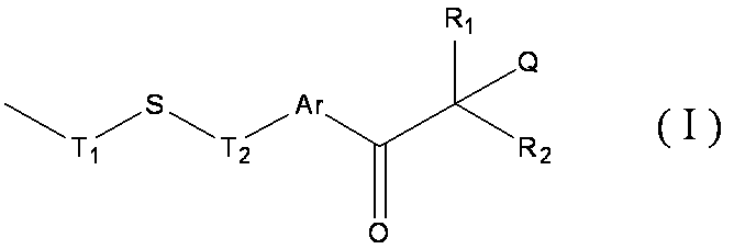


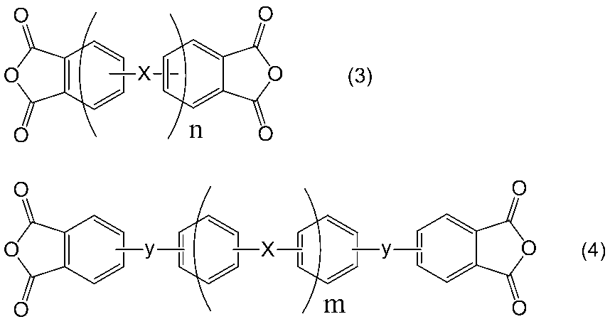
(A)成分:液晶を垂直に配向させる側鎖と、下記式(I)で表される紫外線照射によってラジカルを発生する部位を有する側鎖とを有するポリイミド前駆体、及び、このポリイミド前駆体をイミド化して得られるポリイミドから選択される少なくとも一種の重合体。
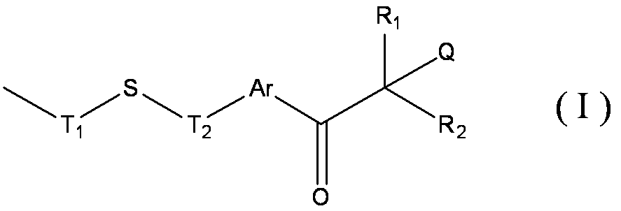


<(A)成分>
本発明の液晶配向剤は、液晶を垂直に配向させる側鎖と、上記式(1)で表される紫外線照射によってラジカルを発生する部位を有する側鎖とを有するポリイミド前駆体、及び、このポリイミド前駆体をイミド化して得られるポリイミドから選択される少なくとも一種の重合体である。
本発明の液晶配向剤に含有される(A)成分には、紫外線照射によりラジカルが発生する部位を側鎖として有している。紫外線照射によりラジカルが発生する部位は下記式(I)で表すことができる。


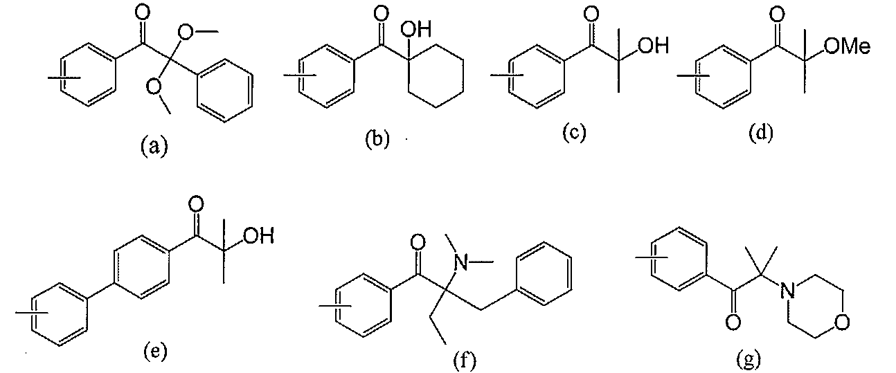
本発明の液晶配向剤に含有される重合体は、上記式(I)で表される側鎖以外に、液晶を垂直に配向させる側鎖を有するのが好ましい。液晶を垂直に配向させる側鎖は、下記の式[II-1]又は式[II-2]で表される。


本発明の液晶配向剤に含有される(A)成分には、上記式(I)で表される側鎖以外に、光反応性の側鎖を有していてもよい。光反応性の側鎖は、紫外線(UV)等の光の照射によって反応し、共有結合を形成し得る官能基(以下、光反応性基ともいう。)を有する。

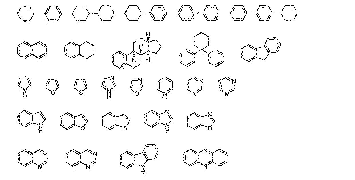
本発明の液晶配向剤を形成する上記の重合体の製造に使用されるジアミン(以下、特定ジアミンともいう。)は、紫外線照射により分解しラジカルが発生する部位を側鎖として有する。


本発明において、特定ジアミンは、各ステップを経てジニトロ体、或いは、還元工程で除去可能な保護基を施したアミノ基を有するモノニトロ体、或いは、ジアミンを合成し、通常用いる還元反応にてニトロ基をアミノ基に変換あるいは保護基を脱保護することにより得ることができる。

液晶を垂直に配向させる側鎖をポリイミド系重合体に導入する方法は、特定側鎖構造を有するジアミンをジアミン成分の一部に用いることが好ましい。特に下記式[2]で示されるジアミン(特定側鎖型ジアミン化合物ともいう)を用いることが好ましい。
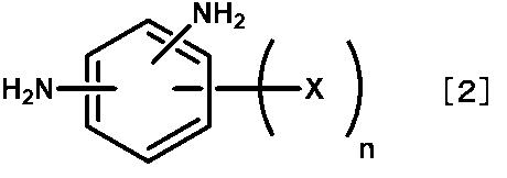



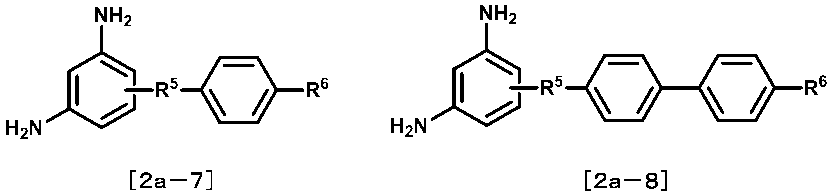

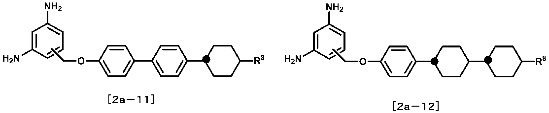




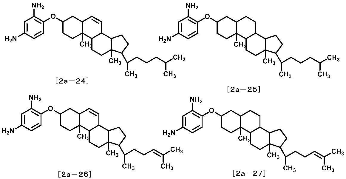
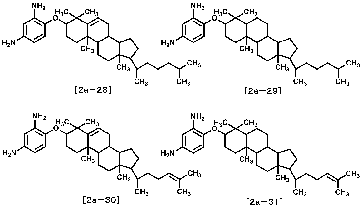
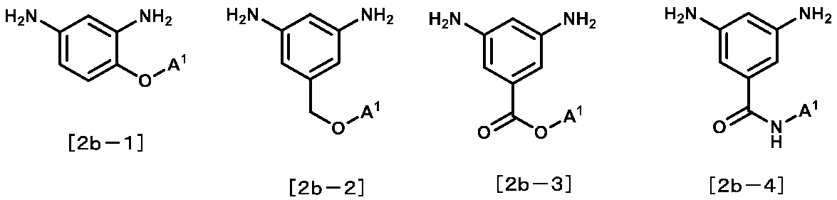
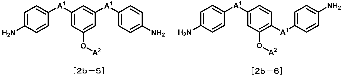

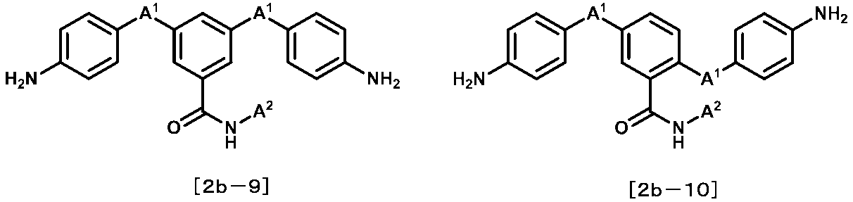
光反応性の側鎖を有するジアミンとしては、例えば、式(3)で表される側鎖を有するジアミンであり、具体的には、下記の一般式(3)で表されるジアミンを挙げることができるが、これに限定されるものではない。

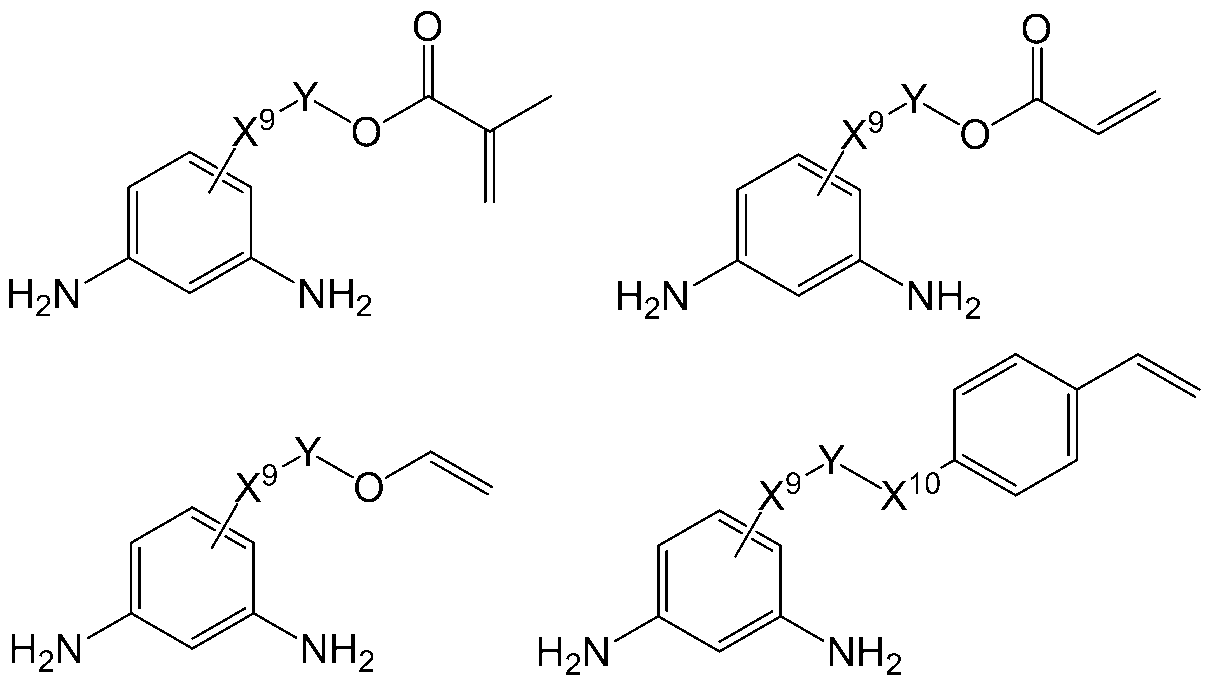

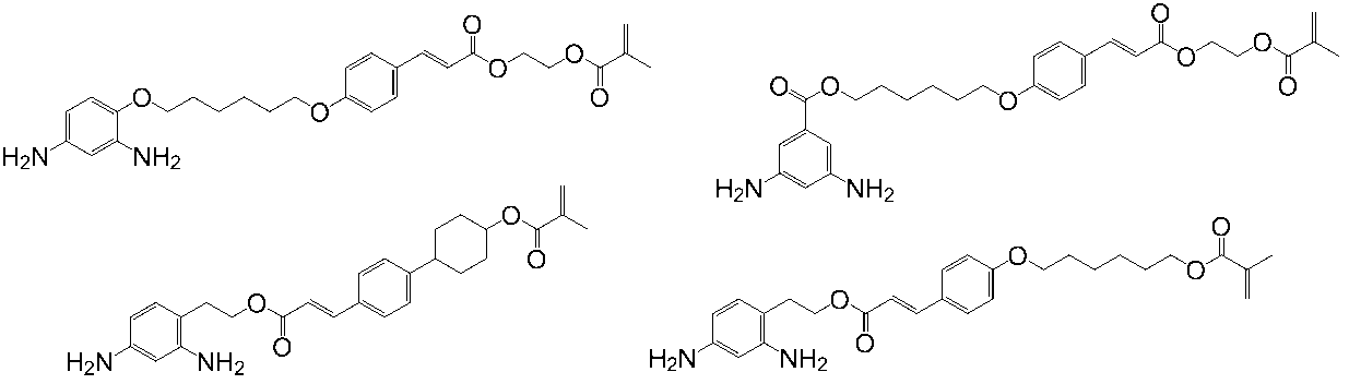
なお、ポリイミド前駆体及び/又は、ポリイミドを製造する場合、本発明の効果を損わない限りにおいて、上記したジアミン以外のその他のジアミンをジアミン成分として併用することができる。具体的には、例えば、p-フェニレンジアミン、2,3,5,6-テトラメチル-p-フェニレンジアミン、2,5-ジメチル-p-フェニレンジアミン、m-フェニレンジアミン、2,4-ジメチル-m-フェニレンジアミン、2,5-ジアミノトルエン、2,6-ジアミノトルエン、2,5-ジアミノフェノール、2,4-ジアミノフェノール、3,5-ジアミノフェノール、3,5-ジアミノベンジルアルコール、2,4-ジアミノベンジルアルコール、4,6-ジアミノレゾルシノール、4,4’-ジアミノビフェニル、3,3’-ジメチル-4,4’-ジアミノビフェニル、3,3’-ジメトキシ-4,4’-ジアミノビフェニル、3,3’-ジヒドロキシ-4,4’-ジアミノビフェニル、3,3’-ジカルボキシ-4,4’-ジアミノビフェニル、3,3’-ジフルオロ-4,4’-ビフェニル、3,3’-トリフルオロメチル-4,4’-ジアミノビフェニル、3,4’-ジアミノビフェニル、3,3’-ジアミノビフェニル、2,2’-ジアミノビフェニル、2,3’-ジアミノビフェニル、4,4’-ジアミノジフェニルメタン、3,3’-ジアミノジフェニルメタン、3,4’-ジアミノジフェニルメタン、2,2’-ジアミノジフェニルメタン、2,3’-ジアミノジフェニルメタン、4,4’-ジアミノジフェニルエーテル、3,3’-ジアミノジフェニルエーテル、3,4’-ジアミノジフェニルエーテル、2,2’-ジアミノジフェニルエーテル、2,3’-ジアミノジフェニルエーテル、4,4’-スルホニルジアニリン、3,3’-スルホニルジアニリン、ビス(4-アミノフェニル)シラン、ビス(3-アミノフェニル)シラン、ジメチル-ビス(4-アミノフェニル)シラン、ジメチル-ビス(3-アミノフェニル)シラン、4,4’-チオジアニリン、3,3’-チオジアニリン、4,4’-ジアミノジフェニルアミン、3,3’-ジアミノジフェニルアミン、3,4’-ジアミノジフェニルアミン、2,2’-ジアミノジフェニルアミン、2,3’-ジアミノジフェニルアミン、N-メチル(4,4’-ジアミノジフェニル)アミン、N-メチル(3,3’-ジアミノジフェニル)アミン、N-メチル(3,4’-ジアミノジフェニル)アミン、N-メチル(2,2’-ジアミノジフェニル)アミン、N-メチル(2,3’-ジアミノジフェニル)アミン、4,4’-ジアミノベンゾフェノン、3,3’-ジアミノベンゾフェノン、3,4’-ジアミノベンゾフェノン、1,4-ジアミノナフタレン、2,2’-ジアミノベンゾフェノン、2,3’-ジアミノベンゾフェノン、1,5-ジアミノナフタレン、1,6-ジアミノナフタレン、1,7-ジアミノナフタレン、1,8-ジアミノナフタレン、2,5-ジアミノナフタレン、2,6-ジアミノナフタレン、2,7-ジアミノナフタレン、2,8-ジアミノナフタレン、1,2-ビス(4-アミノフェニル)エタン、1,2-ビス(3-アミノフェニル)エタン、1,3-ビス(4-アミノフェニル)プロパン、1,3-ビス(3-アミノフェニル)プロパン、1,4-ビス(4-アミノフェニル)ブタン、1,4-ビス(3-アミノフェニル)ブタン、ビス(3,5-ジエチル-4-アミノフェニル)メタン、1,4-ビス(4-アミノフェノキシ)ベンゼン、1,3-ビス(4-アミノフェノキシ)ベンゼン、1,4-ビス(4-アミノフェニル)ベンゼン、1,3-ビス(4-アミノフェニル)ベンゼン、1,4-ビス(4-アミノベンジル)ベンゼン、1,3-ビス(4-アミノフェノキシ)ベンゼン、4,4’-[1,4-フェニレンビス(メチレン)]ジアニリン、4,4’-[1,3-フェニレンビス(メチレン)]ジアニリン、3,4’-[1,4-フェニレンビス(メチレン)]ジアニリン、3,4’-[1,3-フェニレンビス(メチレン)]ジアニリン、3,3’-[1,4-フェニレンビス(メチレン)]ジアニリン、3,3’-[1,3-フェニレンビス(メチレン)]ジアニリン、1,4-フェニレンビス[(4-アミノフェニル)メタノン]、1,4-フェニレンビス[(3-アミノフェニル)メタノン]、1,3-フェニレンビス[(4-アミノフェニル)メタノン]、1,3-フェニレンビス[(3-アミノフェニル)メタノン]、1,4-フェニレンビス(4-アミノベンゾエート)、1,4-フェニレンビス(3-アミノベンゾエート)、1,3-フェニレンビス(4-アミノベンゾエート)、1,3-フェニレンビス(3-アミノベンゾエート)、ビス(4-アミノフェニル)テレフタレート、ビス(3-アミノフェニル)テレフタレート、ビス(4-アミノフェニル)イソフタレート、ビス(3-アミノフェニル)イソフタレート、N,N’-(1,4-フェニレン)ビス(4-アミノベンズアミド)、N,N’-(1,3-フェニレン)ビス(4-アミノベンズアミド)、N,N’-(1,4-フェニレン)ビス(3-アミノベンズアミド)、N,N’-(1,3-フェニレン)ビス(3-アミノベンズアミド)、N,N’-ビス(4-アミノフェニル)テレフタルアミド、N,N’-ビス(3-アミノフェニル)テレフタルアミド、N,N’-ビス(4-アミノフェニル)イソフタルアミド、N,N’-ビス(3-アミノフェニル)イソフタルアミド、9,10-ビス(4-アミノフェニル)アントラセン、4,4’-ビス(4-アミノフェノキシ)ジフェニルスルホン、2,2’-ビス[4-(4-アミノフェノキシ)フェニル]プロパン、2,2’-ビス[4-(4-アミノフェノキシ)フェニル]ヘキサフルオロプロパン、2,2’-ビス(4-アミノフェニル)ヘキサフルオロプロパン、2,2’-ビス(3-アミノフェニル)ヘキサフルオロプロパン、2,2’-ビス(3-アミノ-4-メチルフェニル)ヘキサフルオロプロパン、2,2’-ビス(4-アミノフェニル)プロパン、2,2’-ビス(3-アミノフェニル)プロパン、2,2’-ビス(3-アミノ-4-メチルフェニル)プロパン、3,5-ジアミノ安息香酸、2,5-ジアミノ安息香酸、1,3-ビス(4-アミノフェノキシ)プロパン、1,3-ビス(3-アミノフェノキシ)プロパン、1,4-ビス(4-アミノフェノキシ)ブタン、1,4-ビス(3-アミノフェノキシ)ブタン、1,5-ビス(4-アミノフェノキシ)ペンタン、1,5-ビス(3-アミノフェノキシ)ペンタン、1,6-ビス(4-アミノフェノキシ)へキサン、1,6-ビス(3-アミノフェノキシ)へキサン、1,7-ビス(4-アミノフェノキシ)ヘプタン、1,7-(3-アミノフェノキシ)ヘプタン、1,8-ビス(4-アミノフェノキシ)オクタン、1,8-ビス(3-アミノフェノキシ)オクタン、1,9-ビス(4-アミノフェノキシ)ノナン、1,9-ビス(3-アミノフェノキシ)ノナン、1,10-(4-アミノフェノキシ)デカン、1,10-(3-アミノフェノキシ)デカン、1,11-(4-アミノフェノキシ)ウンデカン、1,11-(3-アミノフェノキシ)ウンデカン、1,12-(4-アミノフェノキシ)ドデカン、1,12-(3-アミノフェノキシ)ドデカンなどの芳香族ジアミン、ビス(4-アミノシクロヘキシル)メタン、ビス(4-アミノ-3-メチルシクロヘキシル)メタンなどの脂環式ジアミン、1,3-ジアミノプロパン、1,4-ジアミノブタン、1,5-ジアミノペンタン、1,6-ジアミノへキサン、1,7-ジアミノヘプタン、1,8-ジアミノオクタン、1,9-ジアミノノナン、1,10-ジアミノデカン、1,11-ジアミノウンデカン、1,12-ジアミノドデカンなどの脂肪族ジアミンが挙げられる。
上記ジアミン成分と反応させるテトラカルボン酸二無水物成分は特に限定されない。具体的には、ピロメリット酸、2,3,6,7-ナフタレンテトラカルボン酸、1,2,5,6-ナフタレンテトラカルボン酸、1,4,5,8-ナフタレンテトラカルボン酸、2,3,6,7-アントラセンテトラカルボン酸、1,2,5,6-アントラセンテトラカルボン酸、3,3’,4,4’-ビフェニルテトラカルボン酸、2,3,3’,4-ビフェニルテトラカルボン酸、ビス(3,4-ジカルボキシフェニル)エーテル、3,3’,4,4’-ベンゾフェノンテトラカルボン酸、ビス(3,4-ジカルボキシフェニル)スルホン、ビス(3,4-ジカルボキシフェニル)メタン、2,2-ビス(3,4-ジカルボキシフェニル)プロパン、1,1,1,3,3,3-ヘキサフルオロ-2,2-ビス(3,4-ジカルボキシフェニル)プロパン、ビス(3,4-ジカルボキシフェニル)ジメチルシラン、ビス(3,4-ジカルボキシフェニル)ジフェニルシラン、2,3,4,5-ピリジンテトラカルボン酸、2,6-ビス(3,4-ジカルボキシフェニル)ピリジン、3,3’,4,4’-ジフェニルスルホンテトラカルボン酸、3,4,9,10-ペリレンテトラカルボン酸、1,3-ジフェニル-1,2,3,4-シクロブタンテトラカルボン酸、オキシジフタルテトラカルボン酸、1,2,3,4-シクロブタンテトラカルボン酸、1,2,3,4-シクロペンタンテトラカルボン酸、1,2,4,5-シクロヘキサンテトラカルボン酸、1,2,3,4-テトラメチル-1,2,3,4-シクロブタンテトラカルボン酸、1,2-ジメチル-1,2,3,4-シクロブタンテトラカルボン酸、1,3-ジメチル-1,2,3,4-シクロブタンテトラカルボン酸、1,2,3,4-シクロヘプタンテトラカルボン酸、2,3,4,5-テトラヒドロフランテトラカルボン酸、3,4-ジカルボキシ-1-シクロへキシルコハク酸、2,3,5-トリカルボキシシクロペンチル酢酸、3,4-ジカルボキシ-1,2,3,4-テトラヒドロ-1-ナフタレンコハク酸、ビシクロ[3,3,0]オクタン-2,4,6,8-テトラカルボン酸、ビシクロ[4,3,0]ノナン-2,4,7,9-テトラカルボン酸、ビシクロ[4,4,0]デカン-2,4,7,9-テトラカルボン酸、ビシクロ[4,4,0]デカン-2,4,8,10-テトラカルボン酸、トリシクロ[6.3.0.0<2,6>]ウンデカン-3,5,9,11-テトラカルボン酸、1,2,3,4-ブタンテトラカルボン酸、4-(2,5-ジオキソテトラヒドロフラン-3-イル)-1,2,3,4-テトラヒドリナフタレン-1,2-ジカルボン酸、ビシクロ[2,2,2]オクト-7-エン-2,3,5,6-テトラカルボン酸、5-(2,5-ジオキソテトラヒドロフリル)-3-メチル-3-シクロへキサン-1,2-ジカルボン酸、テトラシクロ[6,2,1,1,0,2,7]ドデカ-4,5,9,10-テトラカルボン酸、3,5,6-トリカルボキシノルボルナン-2:3,5:6ジカルボン酸、1,2,4,5-シクロヘキサンテトラカルボン酸等から得られるテトラカルボン酸二無水物が挙げられる。勿論、テトラカルボン酸二無水物も、液晶配向膜にした際の液晶配向性、電圧保持特性、蓄積電荷などの特性に応じて、1種類又は2種類以上併用してもよい。
本発明の液晶配向剤は、(B)成分として、下記式(B-1)~(B-5)から選択される少なくとも一種のジアミンを含有するジアミン成分を原料として得られるポリイミド前駆体、及び、このポリイミド前駆体をイミド化して得られるポリイミドから選択される重合体、または、下記式(3)及び(4)から選択される少なくとも一種のテトラカルボン酸二無水物を含有するテトラカルボン酸二無水物成分と、ジアミンの反応により得られるポリイミド前駆体、及び、このポリイミド前駆体をイミド化して得られるポリイミドから選択される重合体を含有する。

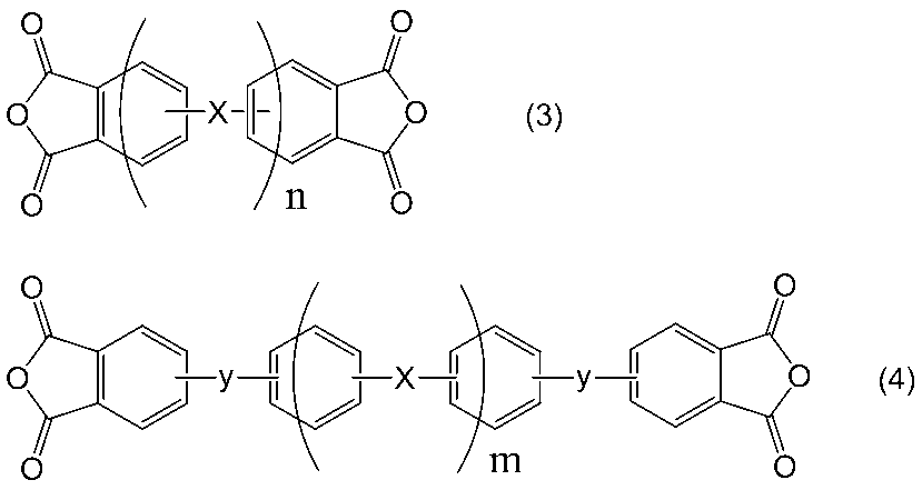

例えば、脂肪族基や脂環族基を有するテトラカルボン酸二無水物も原料とする場合は、ポリアミック酸である(B)成分の合成に用いるテトラカルボン酸二無水物成分の0~90%となる量を用いることが好ましい。
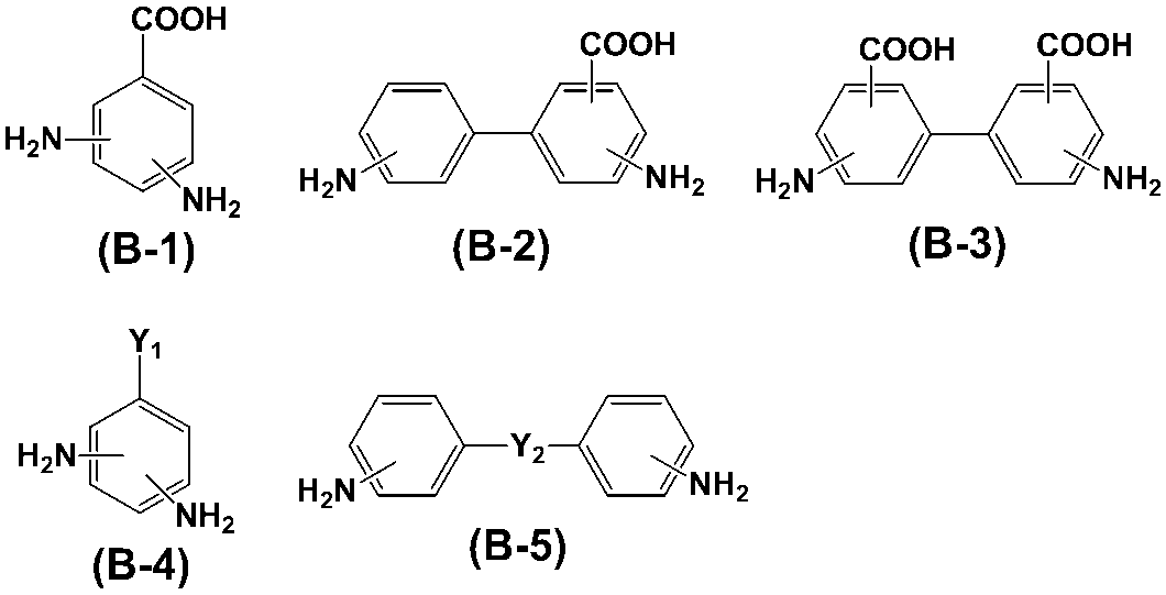

本発明の液晶配向剤には、必要に応じ、2つ以上の末端に光重合又は光架橋する基を有する重合性化合物を含有しても良い。かかる重合性化合物は、光重合又は光架橋する基を有する末端を二つ以上持っている化合物である。ここで、光重合する基を有する重合性化合物とは、光を照射することにより重合を生じさせる官能基を有する化合物である。また、光架橋する基を有する化合物とは、光を照射することにより、重合性化合物の重合体や、ポリイミド前駆体、及び、このポリイミド前駆体をイミド化して得られるポリイミドから選択される少なくとも一種の重合体と反応してこれらと架橋することができる官能基を有する化合物である。なお、光架橋する基を有する化合物は、光架橋する基を有する化合物同士でも反応する。


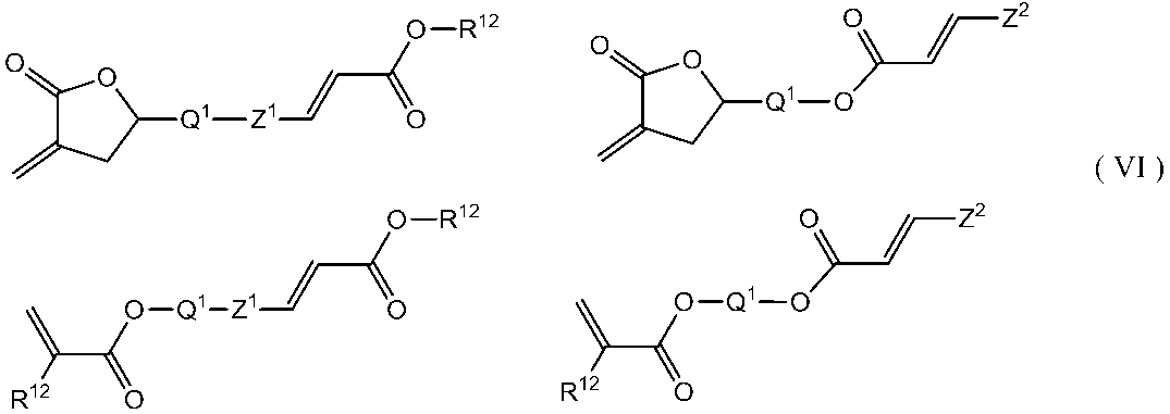


ジアミン成分とテトラカルボン酸二無水物との反応により、ポリアミック酸を得るにあたっては、公知の合成手法を用いることができる。一般的には、ジアミン成分とテトラカルボン酸二無水物成分とを有機溶媒中で反応させる方法である。ジアミン成分とテトラカルボン酸二無水物との反応は、有機溶媒中で比較的容易に進行し、かつ副生成物が発生しない点で有利である。
本発明の液晶配向剤は上記式(1)で表される構造を側鎖に有する少なくとも1つの重合体を含有するが、かかる重合体の含有量は1~20質量%が好ましく、より好ましくは3~15質量%、特に好ましくは3~10質量%である。また、2つ以上の末端に光重合又は光架橋する基をそれぞれ有する重合性化合物を含有する場合、その含有量は、上記重合体100質量部に対して、1~50質量部が好ましく、さらに好ましくは5~30質量部である。
本発明の液晶表示素子は、上記の方法により、基板に液晶配向膜を形成した後、公知の方法で液晶セルを作製できる。液晶表示素子の具体例としては、対向するように配置された2枚の基板と、基板間に設けられた液晶層と、基板と液晶層との間に設けられ本発明の液晶配向剤により形成された上記液晶配向膜とを有する液晶セルを具備する垂直配向方式の液晶表示素子である。具体的には、本発明の液晶配向剤を2枚の基板上に塗布して焼成することにより液晶配向膜を形成し、この液晶配向膜が対向するように2枚の基板を配置し、この2枚の基板の間に液晶で構成された液晶層を挟持し、すなわち、液晶配向膜に接触させて液晶層を設け、液晶配向膜及び液晶層に電圧を印加しながら紫外線を照射することで作製される液晶セルを具備する垂直配向方式の液晶表示素子である。

下記液晶配向剤の調製で用いた略号は以下のとおりである。
(酸二無水物)
BODA:ビシクロ[3,3,0]オクタン-2,4,6,8-テトラカルボン酸二無水物
CBDA:1,2,3,4-シクロブタンテトラカルボン酸二無水物
PMDA:ピロメリット酸二無水物
TCA:2,3,5-トリカルボキシシクロペンチル酢酸-1,4,2,3-二無水物
(ジアミン)
p-PDA:p-フェニレンジアミン
DBA:3,5-ジアミノ安息香酸
3AMPDA:3,5-ジアミノ-N-(ピリジン-3-イルメチル)ベンズアミド


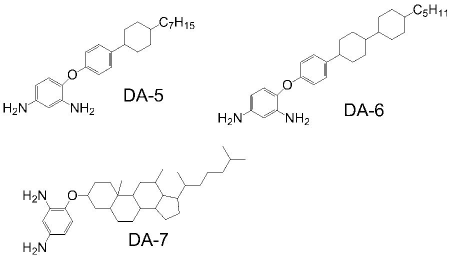

NMP:N-メチル-2-ピロリドン
BCS:ブチルセロソルブ
<添加剤>
3AMP:3-ピコリルアミン
<重合性化合物>
下記式RM1で表される重合性化合物

装置:センシュー科学社製 常温ゲル浸透クロマトグラフィー(GPC)装置(SSC-7200)
カラム:Shodex社製カラム(KD-803、KD-805)
カラム温度:50℃
溶離液:N,N’-ジメチルホルムアミド(添加剤として、臭化リチウム-水和物(LiBr・H2O)が30mmol/L、リン酸・無水結晶(o-リン酸)が30mmol/L、テトラヒドロフラン(THF)が10ml/L)
流速:1.0ml/分
検量線作成用標準サンプル:東ソー社製 TSK 標準ポリエチレンオキサイド(分子量約9000,000、150,000、100,000、30,000)、および、ポリマーラボラトリー社製 ポリエチレングリコール(分子量 約12,000、4,000、1,000)。
BODA(10.01g、 40.0mmol)、3AMPDA(4.85g、20.0mmol)、DA-2(13.22g、40.0mmol)、DA-5(15.22g、40.0mmol)をNMP(164.6g)中で溶解し、60℃で5時間反応させたのち、CBDA(11.57g、59.0mmol)とNMP(54.9g)を加え、40℃で10時間反応させポリアミック酸溶液を得た。
BODA(10.01g、 40.0mmol)、3AMPDA(4.85g、20.0mmol)、DA-1(14.34g、40.0mmol)、DA-5(15.22g、40.0mmol)をNMP(168.0g)中で溶解し、60℃で5時間反応させたのち、CBDA(11.57g、59.0mmol)とNMP(55.98g)を加え、40℃で10時間反応させポリアミック酸溶液を得た。
BODA(10.01g、40.0mmol)、3AMPDA(4.85g、20.0mmol)、DA-3(13.78g、40.0mmol)、DA-5(15.22g、40.0mmol)をNMP(166.2g)中で溶解し、60℃で5時間反応させたのち、CBDA(11.57g、59.0mmol)とNMP(55.42g)を加え、40℃で10時間反応させポリアミック酸溶液を得た。
TCA(11.21g、50.0mmol)、p-PDA(4.33g、40.0mmol)、DA-3(6.89g、20.0mmol)、DA-5(7.61g、20.0mmol)、DA-7(9.90g、20.0mmol)をNMP(148.6g)中で溶解し、80℃で5時間反応させたのち、CBDA(9.61g、49.0mmol)とNMP(49.54g)を加え、40℃で10時間反応させポリアミック酸溶液を得た。
BODA(10.01g、40.0mmol)、DA-4(7.93g、30.0mmol)、DA-3(10.33g、30.0mmol)、DA-5(7.61g、20.0mmol)、DA-6(8.69g、20.0mmol)をNMP(168.4g)中で溶解し、80℃で5時間反応させたのち、CBDA(11.57g、49.0mmol)とNMP(56.14g)を加え、40℃で10時間反応させポリアミック酸溶液を得た。
BODA(18.77g、75.0mmol)、DBA(3.04g、20.0mmol)、DA-8(9.96g、50.0mmol)、DA-5(11.42g、30.0mmol)をNMP(143.7g)中で溶解し、60℃で5時間反応させたのち、CBDA(4.12g、21.0mmol)とNMP(47.89g)を加え、40℃で10時間反応させポリアミック酸溶液を得た。
BODA(12.51g、50.0mmol)、DBA(12.93g、85.0mmol)、DA-9(6.16g、15.0mmol)をNMP(123.3g)中で溶解し、60℃で3時間反応させたのち、CBDA(9.51g、48.5mmol)とNMP(41.11g)を加え、40℃で10時間反応させポリアミック酸溶液を得た。
BODA(5.00g、20.0mmol)、DBA(6.09g、40.0mmol)、3AMPDA(7.27g、30.0mmol)、DA-5(11.42g、30.0mmol)をNMP(136.5g)中で溶解し、60℃で3時間反応させたのち、PMDA(4.36g、48.5mmol)とCBDA(11.37g、58.0mmol)とNMP(45.51g)を加え、40℃で10時間反応させポリアミック酸溶液を得た。

合成例1で得られた液晶配向剤(U1)を第1成分として3.0g、実施例5で得られた液晶配向剤(L1)を第2成分として7.0gを混合し、1時間撹拌することにより液晶配向剤(A1)を調製した。
実施例1で得られた液晶配向剤(A1)を用いて下記に示すような手順で液晶セルの作製を行った。実施例1で得られた液晶配向剤(A1)を、画素サイズが100μm×300μmでライン/スペースがそれぞれ5μmのITO電極パターンが形成されているITO電極基板のITO面にスピンコートし、80℃のホットプレートで90秒間乾燥した後、200℃の熱風循環式オーブンで30分間焼成を行い、膜厚100nmの液晶配向膜を形成した。
また、各セルの残留DC電圧を測定した。結果を表に示す。
まず、バックライト、クロスニコルの状態にした一組の偏光版、光量検出器の順で構成される測定装置において、一組の偏光版の間に液晶セルを配置した。このときライン/スペースが形成されているITO電極のパターンがクロスニコルに対して45°の角度になるようにした。そして、上記の液晶セルに電圧±7V、周波数1kHzの矩形波を印加し、光量検出器によって観測される輝度が飽和するまでの変化をオシロスコープにて取り込み、電圧を印加していない時の輝度を0%、±6Vの電圧を印加し、飽和した輝度の値を100%として、輝度が10%から90%まで変化するのにかかる時間を応答速度とした。
名菱テクニカ製LCDアナライザーLCA-LUV42Aを使用した。
上記で製造した液晶セルに対し、直流2Vを重畳した30Hz、7.8Vppの矩形波を23℃で100時間印加し、直流電圧を切った直後の液晶セル内に残留した電圧(残留DC電圧)をフリッカー消去法により求めた。この値はDC蓄積により発生する残像の指標となり、この値がおおむね30mV以下であるとき、残像特性に優れていると判断した。
液晶配向剤(L1)を液晶配向剤(L2)とした以外は、実施例1と同様の操作を行い液晶配向剤(A2)を調製した。さらに実施例1と同様の操作を行い応答速度、プレチルト角、残留DC電圧を測定した。
液晶配向剤(L1)を液晶配向剤(L3)とした以外は、実施例1と同様の操作を行い液晶配向剤(A3)を調製した。さらに実施例1と同様の操作を行い応答速度、プレチルト角、残留DC電圧を測定した。
液晶配向剤(U1)を液晶配向剤(U2)とした以外は、実施例1と同様の操作を行い液晶配向剤(A4)を調製した。さらに実施例1と同様の操作を行い応答速度、プレチルト角、残留DC電圧を測定した。
液晶配向剤(L1)を液晶配向剤(L2)とした以外は、実施例4と同様の操作を行い液晶配向剤(A5)を調製した。さらに実施例1と同様の操作を行い応答速度、プレチルト角、残留DC電圧を測定した。
液晶配向剤(L1)を液晶配向剤(L3)とした以外は、実施例4と同様の操作を行い液晶配向剤(A6)を調製した。さらに実施例1と同様の操作を行い応答速度、プレチルト角、残留DC電圧を測定した。
液晶配向剤(U1)を液晶配向剤(U3)とした以外は、実施例1と同様の操作を行い液晶配向剤(A7)を調製した。さらに実施例1と同様の操作を行い応答速度、プレチルト角、残留DC電圧を測定した。
液晶配向剤(L1)を液晶配向剤(L2)とした以外は、実施例7と同様の操作を行い液晶配向剤(A8)を調製した。さらに実施例1と同様の操作を行い応答速度、プレチルト角、残留DC電圧を測定した。
液晶配向剤(L1)を液晶配向剤(L3)とした以外は、実施例7と同様の操作を行い液晶配向剤(A9)を調製した。さらに実施例1と同様の操作を行い応答速度、プレチルト角、残留DC電圧を測定した。
液晶配向剤(U1)を液晶配向剤(U4)とした以外は、実施例1と同様の操作を行い液晶配向剤(A10)を調製した。さらに実施例1と同様の操作を行い応答速度、プレチルト角、残留DC電圧を測定した。
液晶配向剤(L1)を液晶配向剤(L2)とした以外は、実施例10と同様の操作を行い液晶配向剤(A11)を調製した。さらに実施例1と同様の操作を行い応答速度、プレチルト角、残留DC電圧を測定した。
液晶配向剤(L1)を液晶配向剤(L3)とした以外は、実施例10と同様の操作を行い液晶配向剤(A12)を調製した。さらに実施例1と同様の操作を行い応答速度、プレチルト角、残留DC電圧を測定した。
液晶配向剤(U1)を液晶配向剤(U5)とした以外は、実施例1と同様の操作を行い液晶配向剤(A13)を調製した。さらに実施例1と同様の操作を行い応答速度、プレチルト角、残留DC電圧を測定した。
液晶配向剤(L1)を液晶配向剤(L2)とした以外は、実施例13と同様の操作を行い液晶配向剤(A14)を調製した。さらに実施例1と同様の操作を行い応答速度、プレチルト角、残留DC電圧を測定した。
液晶配向剤(L1)を液晶配向剤(L3)とした以外は、実施例13と同様の操作を行い液晶配向剤(A15)を調製した。さらに実施例1と同様の操作を行い応答速度、プレチルト角、残留DC電圧を測定した。
液晶配向剤(U5)を第1成分として5.0g、液晶配向剤(L1)を第2成分として5.0g、さらに重合性化合物として0.06g(液晶配向剤の固形分に対して10質量%)を混合し、1時間撹拌することにより液晶配向剤(A16)を調製した。さらにPSA用重合性化合物を含んでいない液晶としてMLC-6608を用いた以外は実施例1と同様の操作を行い応答速度、プレチルト角、残留DC電圧を測定した。
液晶配向剤として液晶配向剤(U1)を用いた以外は実施例1と同様の操作を行い応答速度、プレチルト角、残留DC電圧を測定した。
液晶配向剤として液晶配向剤(U2)を用いた以外は実施例1と同様の操作を行い応答速度、プレチルト角、残留DC電圧を測定した。
液晶配向剤として液晶配向剤(U3)を用いた以外は実施例1と同様の操作を行い応答速度、プレチルト角、残留DC電圧を測定した。
液晶配向剤として液晶配向剤(U4)を用いた以外は実施例1と同様の操作を行い応答速度、プレチルト角、残留DC電圧を測定した。
液晶配向剤として液晶配向剤(U5)を用いた以外は実施例1と同様の操作を行い応答速度、プレチルト角、残留DC電圧を測定した。

一方で、比較例では成分2が導入されていないため、長時間のDC印加によって残留DC電圧が蓄積していることが確認された。
以上のように、ラジカル発生構造を有する第一の成分と残留DC電圧の抑制に効果のある第二の成分を併用することで、長波長(例えば365nm)の紫外線照射でも応答速度が向上でき、かつ、残像特性に優れた液晶表示素子を提供することが可能となる。
Claims (4)
- 下記(A)成分、(B)成分及び有機溶剤を含有することを特徴とする液晶配向剤。
(A)成分:液晶を垂直に配向させる側鎖と、下記式(1)で表される紫外線照射によってラジカルを発生する部位を有する側鎖とを有するポリイミド前駆体、及び、このポリイミド前駆体をイミド化して得られるポリイミドから選択される少なくとも一種の重合体。


(B)成分:下記式(B-1)~(B-5)から選択される少なくとも一種のジアミンを含有するジアミン成分を原料として得られるポリイミド前駆体、及び、このポリイミド前駆体をイミド化して得られるポリイミドから選択される重合体、または、下記式(3)及び(4)から選択される少なくとも一種のテトラカルボン酸二無水物を含有するテトラカルボン酸二無水物成分を原料として得られるポリイミド前駆体、及び、このポリイミド前駆体をイミド化して得られるポリイミドから選択される重合体。

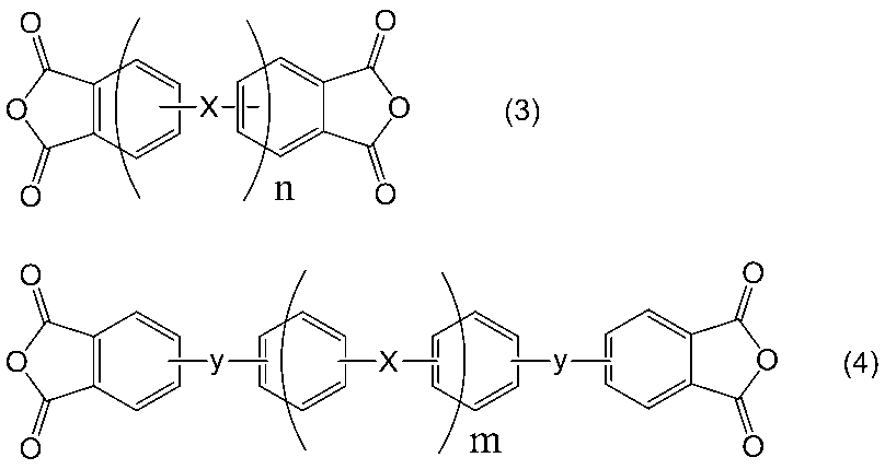
- 請求項1に記載の液晶配向剤を基板に塗布し、焼成して得られることを特徴とする液晶配向膜。
- 請求項1に記載の液晶配向剤を基板に塗布し焼成して得られた液晶配向膜に接触させて液晶層を設け、この液晶層に電圧を印可しながら紫外線を照射して液晶セルを具備することを特徴とする液晶表示素子。
- 請求項1に記載の液晶配向剤を基板に塗布し焼成して得られた液晶配向膜に接触させて液晶層を設け、この液晶層に電圧を印可しながら紫外線を照射して液晶セルを作製することを特徴とする液晶表示素子の製造方法。
Priority Applications (3)
| Application Number | Priority Date | Filing Date | Title |
|---|---|---|---|
| JP2017503703A JP6635272B2 (ja) | 2015-03-04 | 2016-03-02 | 液晶配向剤、液晶配向膜及び液晶表示素子 |
| CN201680025645.8A CN107533259B (zh) | 2015-03-04 | 2016-03-02 | 液晶取向剂、液晶取向膜及液晶表示元件 |
| KR1020177027821A KR102609036B1 (ko) | 2015-03-04 | 2016-03-02 | 액정 배향제, 액정 배향막 및 액정 표시 소자 |
Applications Claiming Priority (2)
| Application Number | Priority Date | Filing Date | Title |
|---|---|---|---|
| JP2015042878 | 2015-03-04 | ||
| JP2015-042878 | 2015-03-04 |
Publications (1)
| Publication Number | Publication Date |
|---|---|
| WO2016140288A1 true WO2016140288A1 (ja) | 2016-09-09 |
Family
ID=56848536
Family Applications (1)
| Application Number | Title | Priority Date | Filing Date |
|---|---|---|---|
| PCT/JP2016/056506 Ceased WO2016140288A1 (ja) | 2015-03-04 | 2016-03-02 | 液晶配向剤、液晶配向膜及び液晶表示素子 |
Country Status (5)
| Country | Link |
|---|---|
| JP (1) | JP6635272B2 (ja) |
| KR (1) | KR102609036B1 (ja) |
| CN (1) | CN107533259B (ja) |
| TW (1) | TWI596158B (ja) |
| WO (1) | WO2016140288A1 (ja) |
Cited By (7)
| Publication number | Priority date | Publication date | Assignee | Title |
|---|---|---|---|---|
| JP2018081225A (ja) * | 2016-11-17 | 2018-05-24 | Jsr株式会社 | 液晶配向剤、液晶素子の製造方法、液晶配向膜、液晶素子、重合体 |
| WO2018097155A1 (ja) * | 2016-11-22 | 2018-05-31 | 日産化学工業株式会社 | 液晶表示素子の製造方法並びに液晶表示素子用基板及び液晶表示素子組立体 |
| WO2019004433A1 (ja) * | 2017-06-30 | 2019-01-03 | 日産化学株式会社 | ゼロ面アンカリング膜の製造方法及び液晶表示素子 |
| WO2019131810A1 (ja) * | 2017-12-27 | 2019-07-04 | 日産化学株式会社 | ゼロ面アンカリング膜の製造方法及び液晶表示素子 |
| WO2019244820A1 (ja) * | 2018-06-18 | 2019-12-26 | 日産化学株式会社 | ゼロ面アンカリング膜の製造方法及び液晶表示素子 |
| WO2020085450A1 (ja) * | 2018-10-26 | 2020-04-30 | 日産化学株式会社 | 液晶配向剤、液晶配向膜、及び液晶表示素子 |
| JPWO2019082913A1 (ja) * | 2017-10-25 | 2020-11-19 | 日産化学株式会社 | 液晶配向剤、液晶配向膜及び液晶表示素子 |
Families Citing this family (4)
| Publication number | Priority date | Publication date | Assignee | Title |
|---|---|---|---|---|
| WO2018159733A1 (ja) * | 2017-03-02 | 2018-09-07 | 日産化学株式会社 | 液晶配向剤、液晶配向膜及び液晶表示素子 |
| JP7425415B2 (ja) * | 2019-01-22 | 2024-01-31 | 日産化学株式会社 | 液晶配向剤、液晶配向膜及び液晶表示素子 |
| WO2021125329A1 (ja) * | 2019-12-18 | 2021-06-24 | 日産化学株式会社 | ラジカル発生膜形成組成物、ラジカル発生膜、及び横電界液晶セルの製造方法 |
| CN117510845B (zh) * | 2023-11-08 | 2024-06-25 | 波米科技有限公司 | 一种具有高预倾角的液晶取向剂及其应用 |
Citations (2)
| Publication number | Priority date | Publication date | Assignee | Title |
|---|---|---|---|---|
| WO2014038431A1 (ja) * | 2012-09-05 | 2014-03-13 | シャープ株式会社 | 配向膜用重合体、及び、液晶表示装置 |
| WO2015115588A1 (ja) * | 2014-01-30 | 2015-08-06 | 日産化学工業株式会社 | 液晶配向剤、液晶配向膜、及び液晶表示素子 |
Family Cites Families (8)
| Publication number | Priority date | Publication date | Assignee | Title |
|---|---|---|---|---|
| JP4175826B2 (ja) | 2002-04-16 | 2008-11-05 | シャープ株式会社 | 液晶表示装置 |
| JP2007002065A (ja) * | 2005-06-22 | 2007-01-11 | Fujifilm Holdings Corp | 液晶材料、その製造方法、及び、該液晶材料を含む表示素子 |
| WO2012133819A1 (ja) * | 2011-03-31 | 2012-10-04 | 日産化学工業株式会社 | 液晶配向剤、液晶配向膜、液晶表示素子及び液晶表示素子の製造方法並びに重合性化合物 |
| KR101986398B1 (ko) * | 2011-12-28 | 2019-06-05 | 닛산 가가쿠 가부시키가이샤 | 액정 배향제, 액정 배향막, 액정 표시 소자 및 액정 표시 소자의 제조 방법 |
| CN102964251A (zh) * | 2012-11-14 | 2013-03-13 | 深圳市华星光电技术有限公司 | 感光单体及液晶面板 |
| KR102184058B1 (ko) * | 2013-02-28 | 2020-11-27 | 닛산 가가쿠 가부시키가이샤 | 중합체, 액정 배향 처리제, 액정 배향막 및 액정 표시 소자 |
| KR102255082B1 (ko) * | 2013-09-03 | 2021-05-21 | 닛산 가가쿠 가부시키가이샤 | 액정 배향제, 액정 배향막 및 액정 표시 소자 |
| WO2016125870A1 (ja) * | 2015-02-06 | 2016-08-11 | 日産化学工業株式会社 | 液晶配向剤、液晶表示素子及び液晶表示素子の製造方法 |
-
2016
- 2016-03-02 KR KR1020177027821A patent/KR102609036B1/ko active Active
- 2016-03-02 CN CN201680025645.8A patent/CN107533259B/zh active Active
- 2016-03-02 WO PCT/JP2016/056506 patent/WO2016140288A1/ja not_active Ceased
- 2016-03-02 JP JP2017503703A patent/JP6635272B2/ja active Active
- 2016-03-04 TW TW105106739A patent/TWI596158B/zh active
Patent Citations (2)
| Publication number | Priority date | Publication date | Assignee | Title |
|---|---|---|---|---|
| WO2014038431A1 (ja) * | 2012-09-05 | 2014-03-13 | シャープ株式会社 | 配向膜用重合体、及び、液晶表示装置 |
| WO2015115588A1 (ja) * | 2014-01-30 | 2015-08-06 | 日産化学工業株式会社 | 液晶配向剤、液晶配向膜、及び液晶表示素子 |
Cited By (23)
| Publication number | Priority date | Publication date | Assignee | Title |
|---|---|---|---|---|
| JP2018081225A (ja) * | 2016-11-17 | 2018-05-24 | Jsr株式会社 | 液晶配向剤、液晶素子の製造方法、液晶配向膜、液晶素子、重合体 |
| WO2018097155A1 (ja) * | 2016-11-22 | 2018-05-31 | 日産化学工業株式会社 | 液晶表示素子の製造方法並びに液晶表示素子用基板及び液晶表示素子組立体 |
| JPWO2018097155A1 (ja) * | 2016-11-22 | 2019-10-17 | 日産化学株式会社 | 液晶表示素子の製造方法並びに液晶表示素子用基板及び液晶表示素子組立体 |
| JP7227557B2 (ja) | 2016-11-22 | 2023-02-22 | 日産化学株式会社 | 液晶表示素子の製造方法 |
| WO2019004433A1 (ja) * | 2017-06-30 | 2019-01-03 | 日産化学株式会社 | ゼロ面アンカリング膜の製造方法及び液晶表示素子 |
| JP7234924B2 (ja) | 2017-06-30 | 2023-03-08 | 日産化学株式会社 | ゼロ面アンカリング膜の製造方法及び液晶表示素子 |
| JPWO2019004433A1 (ja) * | 2017-06-30 | 2020-05-21 | 日産化学株式会社 | ゼロ面アンカリング膜の製造方法及び液晶表示素子 |
| JPWO2019082913A1 (ja) * | 2017-10-25 | 2020-11-19 | 日産化学株式会社 | 液晶配向剤、液晶配向膜及び液晶表示素子 |
| JP7256472B2 (ja) | 2017-10-25 | 2023-04-12 | 日産化学株式会社 | 液晶配向剤、液晶配向膜及び液晶表示素子 |
| JPWO2019131810A1 (ja) * | 2017-12-27 | 2020-12-24 | 日産化学株式会社 | ゼロ面アンカリング膜の製造方法及び液晶表示素子 |
| CN111512221A (zh) * | 2017-12-27 | 2020-08-07 | 日产化学株式会社 | 零面锚定膜的制造方法及液晶显示元件 |
| CN111512221B (zh) * | 2017-12-27 | 2024-04-09 | 日产化学株式会社 | 零面锚定膜的制造方法及液晶显示元件 |
| JP7276149B2 (ja) | 2017-12-27 | 2023-05-18 | 日産化学株式会社 | ゼロ面アンカリング膜の製造方法及び液晶表示素子 |
| WO2019131810A1 (ja) * | 2017-12-27 | 2019-07-04 | 日産化学株式会社 | ゼロ面アンカリング膜の製造方法及び液晶表示素子 |
| WO2019244820A1 (ja) * | 2018-06-18 | 2019-12-26 | 日産化学株式会社 | ゼロ面アンカリング膜の製造方法及び液晶表示素子 |
| JPWO2019244820A1 (ja) * | 2018-06-18 | 2021-07-08 | 日産化学株式会社 | ゼロ面アンカリング膜の製造方法及び液晶表示素子 |
| JP7367673B2 (ja) | 2018-06-18 | 2023-10-24 | 日産化学株式会社 | ゼロ面アンカリング膜の製造方法及び液晶表示素子 |
| CN112313571A (zh) * | 2018-06-18 | 2021-02-02 | 日产化学株式会社 | 零面锚定膜的制造方法及液晶显示元件 |
| WO2020085450A1 (ja) * | 2018-10-26 | 2020-04-30 | 日産化学株式会社 | 液晶配向剤、液晶配向膜、及び液晶表示素子 |
| JPWO2020085450A1 (ja) * | 2018-10-26 | 2021-09-16 | 日産化学株式会社 | 液晶配向剤、液晶配向膜、及び液晶表示素子 |
| KR20210082462A (ko) * | 2018-10-26 | 2021-07-05 | 닛산 가가쿠 가부시키가이샤 | 액정 배향제, 액정 배향막, 및 액정 표시 소자 |
| JP7375766B2 (ja) | 2018-10-26 | 2023-11-08 | 日産化学株式会社 | 液晶配向剤、液晶配向膜、及び液晶表示素子 |
| KR102845022B1 (ko) * | 2018-10-26 | 2025-08-11 | 닛산 가가쿠 가부시키가이샤 | 액정 배향제, 액정 배향막, 및 액정 표시 소자 |
Also Published As
| Publication number | Publication date |
|---|---|
| TWI596158B (zh) | 2017-08-21 |
| JPWO2016140288A1 (ja) | 2017-12-14 |
| KR102609036B1 (ko) | 2023-12-01 |
| JP6635272B2 (ja) | 2020-01-22 |
| TW201704342A (zh) | 2017-02-01 |
| KR20170125080A (ko) | 2017-11-13 |
| CN107533259B (zh) | 2024-06-21 |
| CN107533259A (zh) | 2018-01-02 |
Similar Documents
| Publication | Publication Date | Title |
|---|---|---|
| JP6725885B2 (ja) | 液晶配向剤、液晶配向膜及び液晶表示素子 | |
| JP5387793B2 (ja) | 液晶配向剤 | |
| JP6635272B2 (ja) | 液晶配向剤、液晶配向膜及び液晶表示素子 | |
| JP6662306B2 (ja) | 液晶配向剤、液晶表示素子及び液晶表示素子の製造方法 | |
| JP6864271B2 (ja) | 液晶配向剤、液晶配向膜及び液晶表示素子 | |
| WO2013099937A1 (ja) | 液晶配向剤、液晶配向膜、液晶表示素子及び液晶表示素子の製造方法 | |
| WO2012133820A1 (ja) | 液晶配向剤、液晶配向膜、液晶表示素子及び液晶表示素子の製造方法 | |
| JP7227557B2 (ja) | 液晶表示素子の製造方法 | |
| WO2016140302A1 (ja) | ポリイミド前駆体、並びに該前駆体を有する液晶配向剤、液晶配向膜及び液晶表示素子 | |
| WO2016125871A1 (ja) | 液晶配向剤、液晶配向膜、及び液晶表示素子 | |
| WO2019163904A1 (ja) | 液晶表示素子の製造方法 |
Legal Events
| Date | Code | Title | Description |
|---|---|---|---|
| 121 | Ep: the epo has been informed by wipo that ep was designated in this application |
Ref document number: 16758981 Country of ref document: EP Kind code of ref document: A1 |
|
| ENP | Entry into the national phase |
Ref document number: 2017503703 Country of ref document: JP Kind code of ref document: A |
|
| NENP | Non-entry into the national phase |
Ref country code: DE |
|
| ENP | Entry into the national phase |
Ref document number: 20177027821 Country of ref document: KR Kind code of ref document: A |
|
| WWE | Wipo information: entry into national phase |
Ref document number: 201680025645.8 Country of ref document: CN |
|
| 122 | Ep: pct application non-entry in european phase |
Ref document number: 16758981 Country of ref document: EP Kind code of ref document: A1 |