WO2016139837A1 - 貫流ボイラの火炉壁管の洗浄方法 - Google Patents
貫流ボイラの火炉壁管の洗浄方法 Download PDFInfo
- Publication number
- WO2016139837A1 WO2016139837A1 PCT/JP2015/078193 JP2015078193W WO2016139837A1 WO 2016139837 A1 WO2016139837 A1 WO 2016139837A1 JP 2015078193 W JP2015078193 W JP 2015078193W WO 2016139837 A1 WO2016139837 A1 WO 2016139837A1
- Authority
- WO
- WIPO (PCT)
- Prior art keywords
- cleaning
- scale
- furnace wall
- washing
- boiler
- Prior art date
- Legal status (The legal status is an assumption and is not a legal conclusion. Google has not performed a legal analysis and makes no representation as to the accuracy of the status listed.)
- Ceased
Links
Images


Classifications
-
- F—MECHANICAL ENGINEERING; LIGHTING; HEATING; WEAPONS; BLASTING
- F22—STEAM GENERATION
- F22B—METHODS OF STEAM GENERATION; STEAM BOILERS
- F22B37/00—Component parts or details of steam boilers
- F22B37/02—Component parts or details of steam boilers applicable to more than one kind or type of steam boiler
- F22B37/48—Devices or arrangements for removing water, minerals or sludge from boilers ; Arrangement of cleaning apparatus in boilers; Combinations thereof with boilers
- F22B37/52—Washing-out devices
-
- F—MECHANICAL ENGINEERING; LIGHTING; HEATING; WEAPONS; BLASTING
- F22—STEAM GENERATION
- F22B—METHODS OF STEAM GENERATION; STEAM BOILERS
- F22B37/00—Component parts or details of steam boilers
- F22B37/02—Component parts or details of steam boilers applicable to more than one kind or type of steam boiler
- F22B37/56—Boiler cleaning control devices, e.g. for ascertaining proper duration of boiler blow-down
-
- F—MECHANICAL ENGINEERING; LIGHTING; HEATING; WEAPONS; BLASTING
- F28—HEAT EXCHANGE IN GENERAL
- F28G—CLEANING OF INTERNAL OR EXTERNAL SURFACES OF HEAT-EXCHANGE OR HEAT-TRANSFER CONDUITS, e.g. WATER TUBES OR BOILERS
- F28G9/00—Cleaning by flushing or washing, e.g. with chemical solvents
Definitions
- the present disclosure relates to a method of cleaning a furnace wall tube of a once-through boiler.
- Patent Document 1 discloses chemical cleaning comprising an acid cleaning step of dissolving and removing scale with an acid (inorganic acid or organic acid), a subsequent water cleaning step, and a subsequent rustproofing step. There is. In the acid washing step, the acid solution is circulated to the boiler.
- Patent Document 2 discloses a method of cleaning a natural circulation drum type boiler having a coal saving device, a furnace and a heater.
- a cleaning liquid to which a dispersant is added is injected from the cleaning system temporarily installed in the economizer excluding the heater and the boiler including the furnace into the boiler, it is not possible to hold the cleaning liquid in the boiler. Bubbling by injecting an active gas.
- Patent Document 3 discloses a powder scale discharge method including a water filling step, a pressing step, and a pressure reducing step.
- the water filling step is a step of supplying water to the space to be cleaned, such as an evaporation pipe, with the cleaning fluid into which the microbubbles have been introduced, for water filling.
- the pressurizing step after leaving the state of the water filling step for a predetermined time, the cleaning fluid pressure in the closed space is increased to increase the cleaning fluid pressure, thereby contracting the microbubbles in the cleaning fluid to achieve relative Small micro bubbles and nano bubbles.
- the depressurization step is to expand the bubbles in the cleaning fluid in the form of relatively small microbubbles and nanobubbles by contracting in the pressurization step.
- JP 2012-24735 A JP-A-8-105602 JP, 2014-142154, A
- Patent Documents 1 to 3 require a long time to clean the inner surface of the furnace wall tube, which increases the construction cost and extends the construction period.
- At least one embodiment of the present invention aims to provide a method of cleaning a furnace wall tube of a once-through boiler capable of shortening the cleaning time.
- a method of cleaning a furnace wall tube of a once-through boiler according to at least one embodiment of the present invention, A method for cleaning a furnace wall tube of a once-through boiler, wherein oxygen treatment is applied to a water supply system, Of the autoxidized scale and the powder scale formed on the inner surface of the furnace wall tube, the powder scale having a thermal conductivity lower than that of the autoxidized scale is selectively removed by chemical cleaning.
- the powder scale having a thermal conductivity lower than that of the autoxidized scale is selectively removed by chemical cleaning. Therefore, the cleaning time can be shortened compared to the case of removing all of the autoxidized scale and the powder scale as in the prior art. In addition, since the autoxidized scale is not removed, the cleaning solution will not damage the inner surface of the furnace wall tube.
- a cleaning test step for determining cleaning conditions of the chemical cleaning for selectively removing the powder scale for selectively removing the powder scale; And the washing step of selectively removing the powder scale under the washing conditions determined in the washing test step.
- acid cleaning and chelate cleaning are effective for chemical cleaning, but when the cleaning conditions are high concentration, the cleaning temperature conditions are high temperatures, and the cleaning time conditions are long, the cleaning power is It is too strong to partially damage the self-oxidizing scale, and there are concerns about heat transfer inhibition due to floating of the self-oxidizing scale and corrosion due to the cleaning liquid remaining on the floating portion.
- the cleaning conditions include at least one of a cleaning solution composition condition, a cleaning solution concentration condition, a cleaning temperature condition, and a cleaning time condition.
- the washing conditions include at least one of the washing liquid composition conditions, the washing liquid concentration conditions, the washing temperature conditions or the washing time conditions, the thermal conductivity is higher than that of the self-oxidizing scale under appropriate washing conditions. Powder scale can be selected and removed efficiently.
- the cleaning test process chemically cleans a test body constituted by a part of the furnace wall tube of the once-through boiler to be cleaned or a sample imitating the furnace wall tube, and the cleaning condition is capable of selectively removing the powder scale.
- a test body constituted by a part of the furnace wall tube of the once-through boiler to be cleaned or a sample imitating the furnace wall tube can be chemically cleaned to selectively remove the powder scale. Since the cleaning conditions are determined, the cleaning conditions suitable for each of the flow-through boilers having different operating environments can be determined.
- the particle concentration in the washing liquid used for chemical washing of the test body is monitored to determine the completion timing of the selective removal of the powder scale, and the washing condition is determined based on the completion timing.
- the particle concentration in the washing liquid used for chemical washing of the test body is monitored to determine the completion timing of the selective removal of the powder scale, and the washing condition is determined based on the completion timing. Therefore, the washing conditions can be determined qualitatively.
- the timing at which the increase rate of the particle concentration is less than a threshold is defined as the completion timing.
- the timing at which the rate of increase of the particle concentration is less than the threshold is taken as the completion timing, so that the washing conditions can be determined quantitatively.
- a method of cleaning a furnace wall tube of a once-through boiler capable of shortening the cleaning time.
- a representation representing a relative or absolute arrangement such as “in a direction”, “along a direction”, “parallel”, “orthogonal”, “center”, “concentric” or “coaxial” is strictly Not only does it represent such an arrangement, but also represents a state of relative displacement with an angle or distance that allows the same function to be obtained.
- the expression expressing a shape such as a quadrilateral shape or a cylindrical shape not only represents a shape such as a rectangular shape or a cylindrical shape in a geometrically strict sense, but also an uneven portion The shape including a chamfer etc. shall also be expressed.
- FIG. 1 is a conceptual view showing a schematic configuration of a thermal power plant 1 to which oxygen treatment is applied to a boiler water supply system.
- the method of cleaning the furnace wall tube 5 of the once-through boiler is a method of cleaning the furnace wall tube 5 of the once-through boiler in which oxygen treatment is applied to the water supply system.
- the thermal power plant 1 to which oxygen treatment is applied to the boiler water supply system includes a turbine condenser 11, a condensate pump 12, a condensate processing unit 13, a condensate pressure pump 14, and a low pressure feedwater heater 15.
- the deaerator 16, the boiler feed pump 17, the high pressure feed heater 18, the furnace economizer 19, the super heater 20, and the reheater 21 are provided.
- the furnace economizer 19 includes an economizer 22, a furnace 23, a gas-liquid separator 24, a gas-liquid separation tank 25, and a boiler circulation pump 26.
- FIG. 2 is a conceptual diagram showing a state in which the cleaning and circulation route 3 is installed in the thermal power plant 1 shown in FIG.
- the scale S in which the cleaning solution circulates from the economizer 22 to the gas-liquid separator 24 and adheres to the inner surface of the furnace wall pipe 5 It is to be cleaned and includes a buffer tank 31, a circulation pump 32, a heater 33, and a waste tank 34. These are mutually connected by temporary piping 35.
- the cleaning liquid is stored in the buffer tank 31, and the cleaning liquid stored in the buffer tank 31 is delivered by the circulation pump 32.
- the cleaning liquid delivered by the circulation pump 32 is heated by the heater 33, passes through the economizer 22, the furnace 23, and the gas-liquid separator 24, and is collected in the buffer tank 31.
- the cleaning liquid stored in the buffer tank 31 circulates from the economizer 22 to the gas-liquid separator 24 and cleans and removes the scale S adhering to and deposited on the inner surface of the furnace wall pipe 5 (chemical cleaning) .
- FIG. 3 is a schematic view showing an outline of the furnace wall pipe 5 in which the scale S is adhered and deposited on the inner surface.
- the scale S adhering to and deposited on the inner surface of the furnace wall pipe 5 is configured to include the autoxidation scale HS and the powder scale PS.
- the self-oxidizing scale HS is deposited on the inner surface of the furnace wall tube 5 to form a dense layer, and the powder scale PS is porous with a small particle diameter and attached to the surface of the self-oxidizing scale HS.
- FIG. 4 is a diagram showing the relationship between the thickness of the scale S and the metal temperature.
- the increase in metal temperature is largely influenced by the thickness of the powder scale PS, and is small by the thickness of the autoxidized scale HS.
- the metal temperature of the furnace wall pipe 5 is controlled below the control temperature, but the self-oxidizing scale HS does not grow to a predetermined value (hereinafter referred to as “HS thickness limit value”), and the metal of the furnace wall pipe 5 The temperature never reaches the control temperature.
- FIG. 5 is a view showing the relationship between the operation time of the once-through boiler and the thickness of the self-oxidation scale HS.
- the growth rate of the self-oxidation scale HS is relatively slow, and the thickness is equal to or less than the HS thickness limit value even after about 10 years. Therefore, even if the self-oxidation scale HS is left as it is, the metal temperature of the furnace wall pipe 5 does not reach the control temperature in about 10 years.
- powder scale PS has a smaller thermal conductivity than autoxidized scale HS, and if the thickness grows to a predetermined value (hereinafter referred to as "PS thickness control value"), the metal temperature of furnace wall pipe 5 reaches the control temperature Therefore, the thickness of the powder scale PS is required to be controlled to the PS thickness management value or less.
- PS thickness control value a predetermined value
- powder scale PS is brought in from boiler feed water, adheres and grows, and depends on the water quality of the feed water. Therefore, depending on the quality of the water supplied, the furnace wall pipe 5 may reach the control temperature in two years, or may reach the control temperature in 10 years.
- the thermal conductivity of the autoxidation scale HS and the powder scale PS generated on the inner surface of the furnace wall tube 5 is higher than the autoxidation scale HS.
- the low rate powder scale PS is selectively removed by chemical cleaning.
- the cleaning solution is performed until the powder scale PS having a thermal conductivity lower than that of the autoxidized scale HS is selectively removed by chemical cleaning among the scales S deposited and deposited on the inner surface of the furnace wall pipe 5. Circulate.
- the self-oxidation scale HS and the powder scale PS generated on the inner surface of the furnace wall tube 5 are more than the self-oxidation scale HS. Since the powder scale PS having low thermal conductivity is selectively removed by chemical cleaning, the cleaning time can be shortened as compared with the case of removing all of the autoxidized scale HS and the powder scale PS as in the prior art. In addition, since the self-oxidation scale HS is not removed, the cleaning solution will not damage the inner surface of the furnace wall tube 5.
- FIG. 6 is a conceptual view showing a presumed structure of the furnace wall pipe 5 of the once-through boiler in which the autoxidation scale HS and the powder scale PS are generated on the inner surface.
- the surface layer of the powder scale PS has weak adhesion and can be partially removed by washing with water.
- the powder scale PS and the autoxidation scale HS it has an adhesion which is difficult to remove by washing with water.
- the method of cleaning the furnace wall tube 5 of the once-through boiler includes a cleaning test step and a cleaning step.
- the washing test step is for obtaining washing conditions for chemical washing for selectively removing the powder scale PS, and the washing step is for selectively removing the powder scale PS under the washing conditions obtained in the washing test step.
- the cleaning method of the furnace wall tube 5 of the once-through boiler according to some embodiments described above, chemical cleaning conditions for selectively removing the powder scale PS are determined, and the powder scale PS is selectively eliminated under the determined cleaning conditions. Therefore, the powder scale PS having a thermal conductivity lower than that of the autoxidation scale HS can be efficiently selected and removed among the autoxidation scale HS and the powder scale PS.
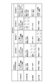
- FIG. 7 is a view showing washing conditions capable of selectively removing powder scale.
- the cleaning conditions include at least one of a cleaning solution composition condition, a cleaning solution concentration condition, a cleaning temperature condition, and a cleaning time condition.
- an organic acid such as citric acid or hydroxy acid is used for the composition of the cleaning solution.
- the concentration of the cleaning solution is 3% to 10%, and the number of times of cleaning depends on the amount of the scale S adhering to the inner surface of the furnace wall tube 5.
- the temperature of the washing solution is 80 ° C. to 90 ° C., and the washing time is about 6 hours to 10 hours.
- a typical chemical cleaning procedure is suitable for removing all the scale S deposited and adhered to the inner surface of the furnace wall tube 5, but is not suitable for selectively removing the powder scale PS. That is, in a typical chemical cleaning procedure, not only powder scale PS but also autoxidation scale HS will be removed.
- the cleaning condition 1 is a reduction in the temperature of the cleaning solution, and the composition of the cleaning solution, the concentration of the cleaning solution, and the cleaning time are the same as the above-described typical chemical cleaning procedures.
- the temperature of the cleaning solution is, for example, normal temperature, which is advantageous in that it is not necessary to heat the cleaning solution.
- the washing under the washing condition 1 suppresses the damage of the autoxidized scale HS and enables selective removal of the powder scale PS.
- the washing condition 2 is obtained by shortening the washing time, and the composition of the washing solution, the concentration of the washing solution, and the temperature of the washing solution are the same as the typical chemical washing procedure described above.
- the washing time is, for example, one hour, which is advantageous in that the washing is completed in a short time.
- the washing under the washing condition 2 suppresses the damage of the autoxidized scale HS and enables selective removal of the powder scale PS.
- the cleaning condition 3 is a reduction in the concentration of the cleaning solution, and the composition of the cleaning solution, the temperature of the cleaning solution, and the cleaning time are the same as the above-described typical chemical cleaning procedures.
- the concentration of the washing solution is, for example, less than 3%, which is advantageous in that the amount of washing solution (stock solution) is reduced.
- the washing under the washing condition 3 suppresses the damage of the autoxidized scale HS and enables selective removal of the powder scale PS.
- the washing condition 4 is an arbitrary modification of the above-mentioned typical chemical washing procedure, and the composition of the washing solution uses an organic acid such as EDTA, malonic acid or hydroxyacetic acid.
- the concentration of the cleaning solution is 3% to 10% or less than 3%, and the number of cleanings depends on the amount of the scale S adhering to the inner surface of the furnace wall tube 5, but the cleaning is usually performed multiple times.
- the temperature of the cleaning solution is 80 ° C. to 90 ° C., or normal temperature, and the cleaning time is about 6 hours to 10 hours, or less than 1 hour.
- the washing under the washing condition 4 suppresses the damage of the autoxidized scale HS and enables selective removal of the powder scale PS.
- the cleaning conditions include at least one of cleaning solution conditions, cleaning solution concentration conditions, cleaning temperature conditions, or cleaning time conditions
- the heat conduction is higher than that of the self-oxidizing scale HS under appropriate cleaning conditions.
- the powder scale PS with a low rate can be selectively removed.
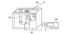
- FIG. 8 is a conceptual view showing an outline of a washing test apparatus for obtaining washing conditions capable of selectively removing powder scale PS.
- an inorganic acid hydrochloric acid
- an organic acid citric acid, hydroxyacetic acid, malonic acid, etc.
- a chelating agent can be used as a washing solution for selectively removing the powder scale PS.
- the cleaning test process chemically cleans a sample TP constituted by a part of the furnace wall pipe 5 of the once-through boiler to be cleaned or a sample imitating the furnace wall pipe 5, and the powder scale Determine washing conditions that can selectively remove PS.
- the scale dissolution test apparatus 6 is used to test a test body TP which constitutes a part of the furnace wall pipe 5 of the once-through boiler to be cleaned.
- the scale dissolution test apparatus 6 includes a warm tank 61, a circulation pump 62, a circulation tank 63, and a particle counter 64.
- the test body TP is immersed in the hot tank 61, and the cleaning liquid stored in the circulation tank 63 is fed out by the circulation pump 62.
- the cleaning fluid delivered by the circulation pump 62 passes through the test body TP and is collected in the circulation tank 63.
- the cleaning liquid stored in the circulation tank 63 circulates the test body TP, and cleans the scale S (powder scale PS) attached to the inner surface of the test body TP.
- the test body TP constituted by a part of the furnace wall pipe 5 of the once-through boiler to be cleaned or the sample imitating the furnace wall pipe is chemically cleaned Since the washing conditions capable of selectively removing the powder scale PS are determined, the washing conditions suitable for each of the through-flow boilers having different operating environments can be determined.
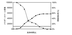
- FIG. 9 is a diagram showing the relationship between the cleaning time and the particle concentration in the cleaning liquid and the rate of increase of the particle concentration.
- the relationship shown in FIG. 9 is merely an example.
- Powder scale is an iron oxide called hematite (Fe 2 O 3 ), which is less soluble compared to the autoxidized scale HS, and it is difficult to completely dissolve it even by chemical cleaning, and its particles are in the cleaning solution. Suspend in floating or stagnant areas. In addition, as the cleaning time increases, the number of particles suspended in the cleaning solution increases, and eventually stagnates in the retention portion.
- hematite Fe 2 O 3
- the completion timing of the selective removal of the powder scale PS is determined by monitoring the particle concentration in the cleaning liquid used for the chemical cleaning of the test object TP, and the completion timing is determined. Determine the washing conditions based on the above.
- the particle concentration is monitored using the particle counter 64 to determine the completion timing of the selective removal of the powder scale PS, and the cleaning time is determined based on the completion timing.
- the particle diameter of the particles to be monitored using the particle counter 64 is set to a predetermined value (for example, 10 ⁇ m), and the disturbance due to the foreign matter or the exfoliation sludge from the self-oxidation scale HS is eliminated.
- the particle concentration is the number of particles in the cleaning solution, and the increase rate of the particle concentration is ⁇ (number of particles at n time)-(number of particles at n-1 hour) ⁇ / (particle at n time) It is calculated by the following equation) * 100.
- the particle concentration generally increases as the washing time increases, and the increase rate of the particle concentration decreases.
- the selective removal of powder scale PS is completed.
- the timing is determined, and the cleaning condition (cleaning time) is determined based on the completion timing.
- the completion timing of the selective removal of the powder scale PS is judged by monitoring the particle concentration in the cleaning liquid used for the chemical cleaning of the test object TP, and completed. Since the cleaning conditions are determined based on the timing, the cleaning conditions can be determined qualitatively.
- the timing at which the increase rate of the particle concentration is less than the threshold is taken as the completion timing.
- the threshold is 10% / time
- the timing at which the increase rate of the particle concentration is less than 10% / hour is the completion timing.
- the cleaning conditions can be quantitatively determined.
- the particle concentration is monitored using the particle counter 64 in the embodiment illustrated in FIG. 8, a simplified monitoring method performed at the time of plant construction or plant startup may be used. Specifically, after filtering sample water using a membrane filter, a method may be used to estimate the iron concentration by the color of the filter. In this case, the timing at which the increase in the concentration of particles contained in the cleaning liquid is not recognized is taken as the completion timing.
- the present invention is not limited to the above-described embodiments, and includes the embodiments in which the above-described embodiments are modified or the embodiments in which these embodiments are appropriately combined.
Landscapes
- Engineering & Computer Science (AREA)
- Mechanical Engineering (AREA)
- General Engineering & Computer Science (AREA)
- Physics & Mathematics (AREA)
- Thermal Sciences (AREA)
- Chemical & Material Sciences (AREA)
- Combustion & Propulsion (AREA)
- Cleaning And De-Greasing Of Metallic Materials By Chemical Methods (AREA)
- Cleaning In General (AREA)
- Cleaning By Liquid Or Steam (AREA)
- Baking, Grill, Roasting (AREA)
Abstract
貫流ボイラの火炉壁管(5)の洗浄方法は、給水系統に酸素処理が適用される貫流ボイラの火炉壁管(5)の洗浄方法であって、前記火炉壁管(5)の内面に生成される自己酸化スケール(HS)及びパウダースケール(PS)のうち、前記自己酸化スケール(HS)よりも熱伝導率の低い前記パウダースケール(PS)を化学洗浄により選択除去する。
Description
本開示は、貫流ボイラの火炉壁管の洗浄方法に関する。
ボイラ給水系統に酸素処理が適用される火力発電システムでは、貫流ボイラの火炉壁管のメタル温度が上昇する事象が発生し、火炉壁管破損によるボイラ水の漏洩の発生が問題となっている。火炉壁管のメタル温度の上昇は、低圧給水加熱器ドレン系統または給水系統の配管から鉄が溶出してヘマタイト(Fe2O3)を生成し、ヘマタイトが火炉壁管内面に付着・堆積して熱伝導が悪くなることが原因である(以下、ヘマタイトをその性状からパウダースケールと称する)。
上述の火炉壁管の漏洩不適合を予防するために、定期的に火炉壁管の化学洗浄が実施され、管内面に堆積した鉄系酸化物からなるスケールを完全除去することが行われている。
例えば、特許文献1には、酸(無機酸または有機酸)によりスケールを溶解除去する酸洗浄工程と、その後の水洗浄工程と、その後の防錆処理工程と、を備える化学洗浄が開示されている。かかる酸洗浄工程では、酸溶液をボイラに循環通水する。
また、例えば、特許文献2には、節炭器、火炉及び加熱器を有する自然循環ドラム型ボイラの洗浄方法が開示されている。かかる洗浄方法では、加熱器を除く節炭器、及び火炉を含むボイラに仮設した洗浄系統から分散剤を添加した洗浄液をボイラ内に注入した後、洗浄液をボイラ内に保持している間に不活性ガスを注入してバブリングする。
また、例えば、特許文献3には、水張り工程と、加圧工程と、減圧工程とを備えたパウダースケールの排出方法が開示されている。水張り工程は、マイクロバブルを導入した洗浄流体を蒸発管等の洗浄対象空間に供給して水張りする工程である。加圧工程は、水張り工程の状態を所定時間放置した後、閉空間内の洗浄流体圧力を昇圧させることにより、洗浄流体圧力を昇圧させることにより、洗浄流体内のマイクロバブルを収縮させて相対的に小さなマイクロバブル及びナノバブルとするものである。減圧工程は、加圧工程で収縮して相対的に小さなマイクロバブル及びナノバブルの状態にある洗浄流体内のバブルを膨張させるものである。
特許文献1から3に開示された方法では、火炉壁管の管内面を洗浄するのに長時間が必要であり、工事コストが嵩み、施工期間が長期に亘る。
上述の事情に鑑みて、本発明の少なくとも一実施形態は、洗浄時間を短縮できる貫流ボイラの火炉壁管の洗浄方法を提供することを目的とする。
(1)本発明の少なくとも一実施形態に係る貫流ボイラの火炉壁管の洗浄方法は、
給水系統に酸素処理が適用される貫流ボイラの火炉壁管の洗浄方法であって、
前記火炉壁管の内面に生成される自己酸化スケール及びパウダースケールのうち、前記自己酸化スケールよりも熱伝導率の低い前記パウダースケールを化学洗浄により選択除去する。
給水系統に酸素処理が適用される貫流ボイラの火炉壁管の洗浄方法であって、
前記火炉壁管の内面に生成される自己酸化スケール及びパウダースケールのうち、前記自己酸化スケールよりも熱伝導率の低い前記パウダースケールを化学洗浄により選択除去する。
本発明者らによる検討の結果、特許文献1及び2に開示された洗浄方法では、火炉壁管の内面に生成されるスケールを全て除去するため、長時間洗浄が必要であり、工事コストが嵩み、施工期間が長くなるだけでなく、火炉壁管の内面にダメージを与える虞があることがわかった。一方、特許文献に開示された洗浄方法では、洗浄流体にマイクロバブルの供給を受けた純水を用いるが、作動流体の圧力を常圧状態から加圧して昇圧させる一方、昇圧された圧力を減圧させて降圧しなければならず、効率的な洗浄が難しいことがわかった。
この点、上記(1)の方法によれば、火炉壁管の内面に生成される自己酸化スケール及びパウダースケールのうち、自己酸化スケールよりも熱伝導率の低いパウダースケールを化学洗浄により選択除去するので、従来のように自己酸化スケール及びパウダースケールを全部除去する場合よりも洗浄時間を短縮できる。また、自己酸化スケールを除去しないので、洗浄液が火炉壁管の内面にダメージを与えることもなくなる。
(2)幾つかの実施形態では、上記(1)の方法において、
前記パウダースケールを選択除去するための前記化学洗浄の洗浄条件を求める洗浄試験工程と、
前記洗浄試験工程で求められた前記洗浄条件でパウダースケールを選択除去する洗浄工程と
を備える。
前記パウダースケールを選択除去するための前記化学洗浄の洗浄条件を求める洗浄試験工程と、
前記洗浄試験工程で求められた前記洗浄条件でパウダースケールを選択除去する洗浄工程と
を備える。
本発明者らによる検討の結果、化学洗浄には酸洗浄やキレート洗浄等が有効であるが、洗浄液条件を高濃度、洗浄温度条件を高温度、洗浄時間条件を長時間とすると、洗浄力が強すぎて自己酸化スケールを部分的に損傷させ、自己酸化スケールの浮き上がりによる伝熱阻害及び浮き上がり部への洗浄液残留による腐食が懸念される。
この点、上記(2)の方法によれば、パウダースケールを選択除去するための化学洗浄条件を求め、求められた洗浄条件でパウダースケールを選択除去するので、自己酸化スケール及びパウダースケールのうち、自己酸化スケールよりも熱伝導率の低いパウダースケールを効率的に選択除去できる。
(3)幾つかの実施形態では、上記(2)の方法において、
前記洗浄条件は、洗浄液組成条件、洗浄液濃度条件、洗浄温度条件または洗浄時間条件の少なくとも一つを含む。
前記洗浄条件は、洗浄液組成条件、洗浄液濃度条件、洗浄温度条件または洗浄時間条件の少なくとも一つを含む。
上記(3)の方法によれば、洗浄条件は、洗浄液組成条件、洗浄液濃度条件、洗浄温度条件または洗浄時間条件の少なくとも一つを含むので、適切な洗浄条件で自己酸化スケールよりも熱伝導率の低いパウダースケールを効率的に選択除去できる。
(4)幾つかの実施形態では、上記(2)または(3)の方法において、
前記洗浄試験工程は、洗浄対象となる貫流ボイラの火炉壁管の一部又は該火炉壁管を模したサンプルによって構成される試験体を化学洗浄し、前記パウダースケールを選択除去可能な前記洗浄条件を求める。
前記洗浄試験工程は、洗浄対象となる貫流ボイラの火炉壁管の一部又は該火炉壁管を模したサンプルによって構成される試験体を化学洗浄し、前記パウダースケールを選択除去可能な前記洗浄条件を求める。
上記(4)の方法によれば、洗浄対象となる貫流ボイラの火炉壁管の一部又は該火炉壁管を模したサンプルによって構成される試験体を化学洗浄し、パウダースケールを選択除去可能な洗浄条件を求めるので、運転環境の異なる貫流ボイラのそれぞれに適した洗浄条件を求めることができる。
(5)幾つかの実施形態では、上記(4)の方法において、
前記洗浄試験工程では、前記試験体の化学洗浄に用いた洗浄液中における粒子濃度を監視することで、前記パウダースケールの選択除去の完了タイミングを判断し、該完了タイミングに基づいて前記洗浄条件を求める。
前記洗浄試験工程では、前記試験体の化学洗浄に用いた洗浄液中における粒子濃度を監視することで、前記パウダースケールの選択除去の完了タイミングを判断し、該完了タイミングに基づいて前記洗浄条件を求める。
上記(5)の方法によれば、試験体の化学洗浄に用いた洗浄液中における粒子濃度を監視することで、パウダースケールの選択除去の完了タイミングを判断し、完了タイミングに基づいて洗浄条件を求めるので、洗浄条件を定性的に求めることができる。
(6)幾つかの実施形態では、上記(5)の方法において、
前記洗浄試験工程では、前記粒子濃度の上昇率が閾値未満となるタイミングを前記完了タイミングとする。
前記洗浄試験工程では、前記粒子濃度の上昇率が閾値未満となるタイミングを前記完了タイミングとする。
上記(6)の方法によれば、粒子濃度の上昇率が閾値未満となるタイミングを完了タイミングとするので、洗浄条件を定量的に求めることができる。
本発明の少なくとも一実施形態によれば、洗浄時間を短縮できる貫流ボイラの火炉壁管の洗浄方法が提供される。
以下、添付図面を参照して本発明の幾つかの実施形態について説明する。ただし、実施形態として記載されている又は図面に示されている構成部品の寸法、材質、形状、その相対的配置等は、本発明の範囲をこれに限定する趣旨ではなく、単なる説明例にすぎない。
例えば、「ある方向に」、「ある方向に沿って」、「平行」、「直交」、「中心」、「同心」或いは「同軸」等の相対的或いは絶対的な配置を表す表現は、厳密にそのような配置を表すのみならず、公差、若しくは、同じ機能が得られる程度の角度や距離をもって相対的に変位している状態も表すものとする。
また例えば、四角形状や円筒形状等の形状を表す表現は、幾何学的に厳密な意味での四角形状や円筒形状等の形状を表すのみならず、同じ効果が得られる範囲で、凹凸部や面取り部等を含む形状も表すものとする。
一方、一の構成要素を「備える」、「具える」、「具備する」、「含む」、又は、「有する」という表現は、他の構成要素の存在を除外する排他的な表現ではない。
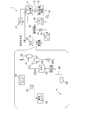
図1は、ボイラ給水系統に酸素処理が適用される火力発電プラント1の概略構成を示す概念図である。
本発明の少なくとも一実施形態に係る貫流ボイラの火炉壁管5の洗浄方法は、給水系統に酸素処理が適用される貫流ボイラの火炉壁管5の洗浄方法である。
図1に示すように、ボイラ給水系統に酸素処理が適用される火力発電プラント1は、タービン復水器11、復水ポンプ12、復水処理装置13、復水昇圧ポンプ14、低圧給水ヒータ15、脱気器16、ボイラ給水ポンプ17、高圧給水ヒータ18、火炉節炭器19、スーパーヒータ20、及びリヒータ21を備えている。そして、火炉節炭器19は、節炭器22、火炉23、気液分離器24、気液分離タンク25、及びボイラ循環ポンプ26を備えている。
図2は、図1に示した火力発電プラント1に洗浄循環経路3を設置した状態を示す概念図である。
図2に示すように、洗浄循環経路3は、洗浄液が節炭器22から気液分離器24の間を循環し、火炉壁管5の内面に付着・堆積したスケールS(図3参照)を洗浄除去するものであり、バッファタンク31、循環ポンプ32、加熱器33、及び廃液タンク34を含んでいる。これらは仮配管35により相互に接続されている。
バッファタンク31には洗浄液が貯留され、バッファタンク31に貯留された洗浄液は、循環ポンプ32で送り出される。循環ポンプ32で送り出された洗浄液は、加熱器33で加熱され、節炭器22、火炉23、及び気液分離器24を通り、バッファタンク31に回収される。これにより、バッファタンク31に貯留された洗浄液は、節炭器22から気液分離器24の間を循環し、火炉壁管5の内面に付着・堆積したスケールSを洗浄除去する(化学洗浄)。
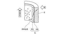
図3は、内面にスケールSが付着・堆積した火炉壁管5の概略を示す模式図である。
図3に示すように、火炉壁管5の内面に付着・堆積するスケールSは、自己酸化スケールHSとパウダースケールPSとを含んで構成されている。自己酸化スケールHSは、火炉壁管5の内面に堆積して緻密な層を成し、パウダースケールPSは、小粒径のポーラス状であり、自己酸化スケールHSの表面に付着している。
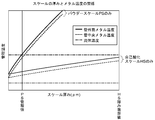
図4は、スケールSの厚みとメタル温度との関係を示した図である。
図4に示すように、メタル温度の上昇は、パウダースケールPSの厚みの影響が大きく、自己酸化スケールHSの厚みの影響は小さい。また、火炉壁管5のメタル温度は管理温度以下で管理されるが、自己酸化スケールHSは厚みが所定値(以下、「HS厚み限界値」という)まで成長しなければ火炉壁管5のメタル温度が管理温度に到達することはない。
図5は、貫流ボイラの運転時間と自己酸化スケールHSの厚みとの関係を示した図である。
図5に示すように、自己酸化スケールHSの成長速度は比較的遅く10年程度経過しても厚みがHS厚み限界値以下である。したがって、自己酸化スケールHSをそのまま残しても火炉壁管5のメタル温度が10年程度で管理温度に到達することはない。
一方、パウダースケールPSは、自己酸化スケールHSよりも熱伝導率が小さく、厚みが所定値(以下「PS厚み管理値」という)まで成長すれば火炉壁管5のメタル温度が管理温度に到達するので、パウダースケールPSの厚みはPS厚み管理値以下に管理することが求められる。
また、パウダースケールPSは、ボイラ給水から持ち込まれ、付着成長するものであり、給水の水質に依存する。したがって、給水の水質により火炉壁管5が2年で管理温度に到達することもあれば、10年で管理温度に到達することもある。
そこで、幾つかの実施形態に係る貫流ボイラの火炉壁管5の洗浄方法は、火炉壁管5の内面に生成される自己酸化スケールHS及びパウダースケールPSのうち、自己酸化スケールHSよりも熱伝導率の低いパウダースケールPSを化学洗浄により選択除去する。
図2に例示する形態では、火炉壁管5の内面に付着・堆積されたスケールSのうち、自己酸化スケールHSよりも熱伝導率の低いパウダースケールPSが化学洗浄により選択除去されるまで、洗浄液を循環する。
上述した幾つかの実施形態に係る貫流ボイラの火炉壁管5の洗浄方法によれば、火炉壁管5の内面に生成される自己酸化スケールHS及びパウダースケールPSのうち、自己酸化スケールHSよりも熱伝導率の低いパウダースケールPSを化学洗浄により選択除去するので、従来のように自己酸化スケールHS及びパウダースケールPSを全部除去する場合よりも洗浄時間を短縮できる。また、自己酸化スケールHSを除去しないので、洗浄液が火炉壁管5の内面にダメージを与えることもなくなる。
図6は、内面に自己酸化スケールHS及びパウダースケールPSが生成された貫流ボイラの火炉壁管5の推定構造を示す概念図である。
パウダースケールPSの表層は、密着力が弱く、水洗でも部分除去可能である。一方、パウダースケールPSと自己酸化スケールHSの界面近傍では水洗では除去困難な程度の密着力を有する。これは、図6に示すように、パウダースケールPSとパウダースケールPS、及びパウダースケールPSと自己酸化スケールHSがマグネタイト等をバインダーBとしていることや、自己酸化スケールHSの表層がミクロ的に粗く、パウダースケールPSが物理的にホールドされていること等が推定される。このため、パウダースケールPSの選択除去においては少なくとも自己酸化スケールHSの表層、またはバインダーBを溶解する必要がある。
これには、酸洗浄やキレート洗浄等が有効であるが、洗浄液条件を高濃度、洗浄温度条件を高温度、洗浄時間条件を長時間とすると、洗浄力が強すぎて自己酸化スケールHSを部分的に損傷させ、自己酸化スケールHSの浮き上がりによる伝熱阻害及び浮き上がり部への洗浄液残留による腐食等が懸念される。
そこで、幾つかの実施形態に係る貫流ボイラの火炉壁管5の洗浄方法は、洗浄試験工程と、洗浄工程とを備える。
洗浄試験工程は、パウダースケールPSを選択除去するための化学洗浄の洗浄条件を求めるものであり、洗浄工程は、洗浄試験工程で求められた洗浄条件でパウダースケールPSを選択除去するものである。
上述した幾つかの実施形態に係る貫流ボイラの火炉壁管5の洗浄方法によれば、パウダースケールPSを選択除去するための化学洗浄条件を求め、求められた洗浄条件でパウダースケールPSを選択除去するので、自己酸化スケールHS及びパウダースケールPSのうち、自己酸化スケールHSよりも熱伝導率の低いパウダースケールPSを効率的に選択除去できる。
図7は、パウダースケールを選択除去可能な洗浄条件を示す図である。
図7に示すように、幾つかの実施形態に係る洗浄条件は、洗浄液組成条件、洗浄液濃度条件、洗浄温度条件または洗浄時間条件の少なくとも一つを含む。
図7に示すように、幾つかの実施形態に係る洗浄条件は、洗浄液組成条件、洗浄液濃度条件、洗浄温度条件または洗浄時間条件の少なくとも一つを含む。
図7に示すように、貫流ボイラの火炉壁管を洗浄するのに代表的な化学洗浄要領では、洗浄液の組成にクエン酸やヒドロキシ酸等の有機酸が用いられる。洗浄液の濃度は、3%から10%で、洗浄回数は火炉壁管5の内面に付着するスケールSの量に左右される。また、洗浄液の温度は、80°Cから90°Cで、洗浄時間は、6時間から10時間程度である。
代表的な化学洗浄要領は、火炉壁管5の内面に堆積・付着したスケールSを全部除去するのに適しているが、パウダースケールPSを選択除去するのには適していない。すなわち、代表的な化学洗浄要領では、パウダースケールPSのみならず自己酸化スケールHSをも除去することになる。
これに対して、洗浄条件1は、洗浄液の温度を低減したもので、洗浄液の組成、洗浄液の濃度、洗浄時間は、上述した代表的な化学洗浄要領と同一としたものである。洗浄液の温度は例えば常温であり、この場合には洗浄液を加熱する必要がなくなる点で有利になる。洗浄条件1による洗浄によれば、自己酸化スケールHSの損傷が抑制され、パウダースケールPSの選択除去が可能となる。
洗浄条件2は、洗浄時間を短縮したもので、洗浄液の組成、洗浄液の濃度、洗浄液の温度は、上述した代表的な化学洗浄要領と同一としたものである。洗浄時間は例えば1時間であり、この場合には短時間で洗浄が終了する点で有利になる。洗浄条件2による洗浄によれば、自己酸化スケールHSの損傷が抑制され、パウダースケールPSの選択除去が可能となる。
洗浄条件3は、洗浄液の濃度を低減したもので、洗浄液の組成、洗浄液の温度、洗浄時間は、上述した代表的な化学洗浄要領と同一としたものである。洗浄液の濃度は例えば3%未満であり、この場合には洗浄液(原液)の量が少なくなる点で有利になる。洗浄条件3による洗浄によれば、自己酸化スケールHSの損傷が抑制され、パウダースケールPSの選択除去が可能となる。
洗浄条件4は、上述した代表的な化学洗浄要領を任意に変更したもので、洗浄液の組成は、EDTA、マロン酸、ヒドロキシ酢酸等の有機酸が用いる。洗浄液の濃度は3%から10%、又は3%未満で、洗浄回数は火炉壁管5の内面に付着するスケールSの量に左右されるが、通常、複数回に亘り洗浄される。また、洗浄液の温度は、80°Cから90°C、又は常温で、洗浄時間は、6時間から10時間程度、又は1時間未満である。洗浄条件4による洗浄によれば、自己酸化スケールHSの損傷が抑制され、パウダースケールPSの選択除去が可能となる。
上述した幾つかの実施形態に係る洗浄条件は、洗浄液組成条件、洗浄液濃度条件、洗浄温度条件、または洗浄時間条件の少なくとも一つを含むので、適切な洗浄条件で自己酸化スケールHSよりも熱伝導率の低いパウダースケールPSを選択除去できる。
図8は、パウダースケールPSを選択除去可能な洗浄条件を求める洗浄試験装置の概略を示す概念図である。
パウダースケールPSを選択除去する洗浄液として、無機酸(塩酸)、有機酸(クエン酸、ヒドロキシ酢酸、マロン酸等)、又はキレート剤の少なくとも一つを用いることができる。
そして、パウダースケールPSのバインダーまたはホルダーが溶解され、または、パウダースケールPSが剥離した段階で洗浄を終了することにより、自己酸化スケールHSの健全性を維持することが望ましい。
しかしながら、パウダースケールPSの溶解、または、パウダースケールPSの剥離に必要な時間は、洗浄液組成条件、洗浄温度条件、及びパウダースケールPSの付着状況により異なる。
幾つかの実施形態に係る洗浄試験工程は、洗浄対象となる貫流ボイラの火炉壁管5の一部又は該火炉壁管5を模したサンプルによって構成される試験体TPを化学洗浄し、パウダースケールPSを選択除去可能な洗浄条件を求める。
図7に例示する形態では、スケール溶解試験装置6を用いて、洗浄対象となる貫流ボイラの火炉壁管5の一部を構成する試験体TPを試験する。スケール溶解試験装置6は、温槽61、循環ポンプ62、循環タンク63、及びパーティクルカウンタ64を備えている。試験体TPは、温槽61に浸漬され、循環タンク63に貯留された洗浄液は、循環ポンプ62で送りだされる。循環ポンプ62で送り出された洗浄液は、試験体TPを通り、循環タンク63に回収される。これにより、循環タンク63に貯留された洗浄液は、試験体TPを循環し、試験体TPの内面に付着したスケールS(パウダースケールPS)を洗浄する。
上述した幾つかの実施形態に係る洗浄試験工程によれば、洗浄対象となる貫流ボイラの火炉壁管5の一部又は該火炉壁管を模したサンプルによって構成される試験体TPを化学洗浄し、パウダースケールPSを選択除去可能な洗浄条件を求めるので、運転環境の異なる貫流ボイラのそれぞれに適した洗浄条件を求めることができる。
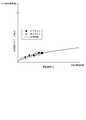
図9は、洗浄時間と洗浄液中における粒子濃度及び粒子濃度の上昇率との関係を示す図である。尚、図9に示す関係は一例に過ぎない。
パウダースケールは、ヘマタイト(Fe2O3)と称される鉄酸化物であり、自己酸化スケールHSに比較して難溶であり、化学洗浄でも完全溶解は困難で、その粒子は、洗浄液中を浮遊または滞留部に堆積する。また、洗浄時間の増加に伴い洗浄液中を浮遊する粒子の個数が増大し、やがて滞留部に停滞する。
そこで、幾つかの実施形態に係る洗浄試験工程では、試験体TPの化学洗浄に用いた洗浄液中における粒子濃度を監視することで、パウダースケールPSの選択除去の完了タイミングを判断し、完了タイミングに基づいて洗浄条件を求める。
図8に例示する形態では、パーティクルカウンタ64を用いて粒子濃度を監視することで、パウダースケールPSの選択除去の完了タイミングを判断し、完了タイミングに基づいて洗浄時間を求める。尚、パーティクルカウンタ64を用いて監視する粒子の粒径を所定値(例えば、10μm)とし、他の異物や自己酸化スケールHSからの剥離スラッジ等による妨害を排除する。
粒子濃度は、洗浄液中の粒子の個数であり、粒子濃度の上昇率は、{(n時間目の粒子の個数)-(n-1時間目の粒子の個数)}/(n時間目の粒子の個数)*100で求められる。
図9に例示するように、一般的に洗浄時間が長くなるのに伴い粒子濃度は高くなり、粒子濃度の上昇率は減少するので、これらを監視することで、パウダースケールPSの選択除去の完了タイミングを判断し、完了タイミングに基づいて洗浄条件(洗浄時間)を求める。
上述した幾つかの実施形態に係る洗浄試験工程によれば、試験体TPの化学洗浄に用いた洗浄液中における粒子濃度を監視することで、パウダースケールPSの選択除去の完了タイミングを判断し、完了タイミングに基づいて洗浄条件を求めるので、洗浄条件を定性的に求めることができる。
幾つかの実施形態に係る洗浄試験工程では、粒子濃度の上昇率が閾値未満となるタイミングを完了タイミングとする。
図9に例示する形態では、10%/時間を閾値とし、粒子濃度の上昇率が10%/時間未満となるタイミングを完了タイミングとする。
上述した幾つかの実施形態に係る洗浄試験工程によれば、粒子濃度の上昇率が閾値未満となるタイミングを完了タイミングとするので、洗浄条件を定量的に求めることができる。
図8に例示する形態では、パーティクルカウンタ64を用いて粒子濃度を監視することとしたが、プラント建設時やプラント起動時に行う簡易モニタリング手法を用いてもよい。具体的には、メンブレンフィルタを用いてサンプル水を濾過後、フィルターの色で鉄濃度を推算する手法を用いてもよい。この場合には、洗浄液に含まれる粒子濃度の上昇が認められなくなったタイミングを完了タイミングとする。
本発明は上述した実施形態に限定されることはなく、上述した実施形態に変形を加えた形態や、これらの形態を適宜組み合わせた形態も含む。
1 火力発電プラント
11 タービン復水器
12 復水ポンプ
13 復水処理装置
14 復水昇圧ポンプ
15 低圧給水ヒータ
16 脱気器
17 ボイラ給水ポンプ
18 高圧給水ヒータ
19 火炉節炭器
20 スーパーヒータ
21 リヒータ
22 節炭器
23 火炉
24 気液分離器
25 気液分離タンク
26 ボイラ循環ポンプ
3 洗浄循環経路
31 バッファタンク
32 循環ポンプ
33 加熱器
34 廃液タンク
35 仮配管
5 火炉壁管
6 スケール溶解試験装置
61 温槽
62 循環ポンプ
63 循環タンク
64 パーティクルカウンタ
S スケール
HS 自己酸化スケール
PS パウダースケール
B バインダー
TP 試験体
11 タービン復水器
12 復水ポンプ
13 復水処理装置
14 復水昇圧ポンプ
15 低圧給水ヒータ
16 脱気器
17 ボイラ給水ポンプ
18 高圧給水ヒータ
19 火炉節炭器
20 スーパーヒータ
21 リヒータ
22 節炭器
23 火炉
24 気液分離器
25 気液分離タンク
26 ボイラ循環ポンプ
3 洗浄循環経路
31 バッファタンク
32 循環ポンプ
33 加熱器
34 廃液タンク
35 仮配管
5 火炉壁管
6 スケール溶解試験装置
61 温槽
62 循環ポンプ
63 循環タンク
64 パーティクルカウンタ
S スケール
HS 自己酸化スケール
PS パウダースケール
B バインダー
TP 試験体
Claims (6)
- 給水系統に酸素処理が適用される貫流ボイラの火炉壁管の洗浄方法であって、
前記火炉壁管の内面に生成される自己酸化スケール及びパウダースケールのうち、前記自己酸化スケールよりも熱伝導率の低い前記パウダースケールを化学洗浄により選択除去すること
を特徴とする貫流ボイラの火炉壁管の洗浄方法。 - 前記パウダースケールを選択除去するための前記化学洗浄の洗浄条件を求める洗浄試験工程と、
前記洗浄試験工程で求められた前記洗浄条件でパウダースケールを選択除去する洗浄工程と
を備えることを特徴とする請求項1に記載の貫流ボイラの火炉壁管の洗浄方法。 - 前記洗浄条件は、洗浄液組成条件、洗浄液濃度条件、洗浄温度条件または洗浄時間条件の少なくとも一つを含むこと
を特徴とする請求項2に記載の貫流ボイラの火炉壁管の洗浄方法。 - 前記洗浄試験工程は、洗浄対象となる貫流ボイラの火炉壁管の一部又は該火炉壁管を模したサンプルによって構成される試験体を化学洗浄し、前記パウダースケールを選択除去可能な前記洗浄条件を求めること
を特徴とする請求項2または3に記載の貫流ボイラの火炉壁管の洗浄方法。 - 前記洗浄試験工程では、前記試験体の化学洗浄に用いた洗浄液中における粒子濃度を監視することで、前記パウダースケールの選択除去の完了タイミングを判断し、該完了タイミングに基づいて前記洗浄条件を求めること
を特徴とする請求項4に記載の貫流ボイラの火炉壁管の洗浄方法。 - 前記洗浄試験工程では、前記粒子濃度の上昇率が閾値未満となるタイミングを前記完了タイミングとすること
を特徴とする請求項5に記載の貫流ボイラの火炉壁管の洗浄方法。
Priority Applications (2)
| Application Number | Priority Date | Filing Date | Title |
|---|---|---|---|
| SG11201706388PA SG11201706388PA (en) | 2015-03-04 | 2015-10-05 | Method for cleaning furnace wall tube of once-through boiler |
| CN201580075312.1A CN107208879B (zh) | 2015-03-04 | 2015-10-05 | 直流锅炉的火炉壁管的清洗方法 |
Applications Claiming Priority (2)
| Application Number | Priority Date | Filing Date | Title |
|---|---|---|---|
| JP2015-042501 | 2015-03-04 | ||
| JP2015042501A JP6363037B2 (ja) | 2015-03-04 | 2015-03-04 | 貫流ボイラの火炉壁管の洗浄方法 |
Publications (1)
| Publication Number | Publication Date |
|---|---|
| WO2016139837A1 true WO2016139837A1 (ja) | 2016-09-09 |
Family
ID=56846565
Family Applications (1)
| Application Number | Title | Priority Date | Filing Date |
|---|---|---|---|
| PCT/JP2015/078193 Ceased WO2016139837A1 (ja) | 2015-03-04 | 2015-10-05 | 貫流ボイラの火炉壁管の洗浄方法 |
Country Status (5)
| Country | Link |
|---|---|
| JP (1) | JP6363037B2 (ja) |
| CN (1) | CN107208879B (ja) |
| SG (1) | SG11201706388PA (ja) |
| TW (1) | TWI593929B (ja) |
| WO (1) | WO2016139837A1 (ja) |
Cited By (1)
| Publication number | Priority date | Publication date | Assignee | Title |
|---|---|---|---|---|
| JP2020067240A (ja) * | 2018-10-25 | 2020-04-30 | 東京電力ホールディングス株式会社 | ボイラの化学洗浄方法 |
Families Citing this family (2)
| Publication number | Priority date | Publication date | Assignee | Title |
|---|---|---|---|---|
| JP6774148B2 (ja) * | 2017-04-12 | 2020-10-21 | 三菱パワー株式会社 | スケール除去方法及びスケール除去装置 |
| JP7051474B2 (ja) * | 2018-02-09 | 2022-04-11 | 三菱重工業株式会社 | 化学洗浄装置及びそれを用いた化学洗浄方法 |
Citations (4)
| Publication number | Priority date | Publication date | Assignee | Title |
|---|---|---|---|---|
| JP2011227011A (ja) * | 2010-04-23 | 2011-11-10 | Babcock-Hitachi Co Ltd | スケール熱伝導率測定装置 |
| JP2014153033A (ja) * | 2013-02-13 | 2014-08-25 | Babcock-Hitachi Co Ltd | ボイラ装置の保全方法 |
| WO2014162992A1 (ja) * | 2013-04-02 | 2014-10-09 | 栗田工業株式会社 | 蒸気発生設備のスケール除去方法 |
| JP5721888B1 (ja) * | 2014-07-04 | 2015-05-20 | 三菱日立パワーシステムズ株式会社 | 化学洗浄方法及び化学洗浄装置 |
Family Cites Families (5)
| Publication number | Priority date | Publication date | Assignee | Title |
|---|---|---|---|---|
| US5037483A (en) * | 1990-01-30 | 1991-08-06 | Nalco Chemical Company | On-line iron clean-up |
| CN2633878Y (zh) * | 2003-07-18 | 2004-08-18 | 来庆东 | 自净化锅炉 |
| JP2006322672A (ja) * | 2005-05-19 | 2006-11-30 | Ebara Kogyo Senjo Kk | ドラム型ボイラスケールの一貫洗浄方法およびそのための洗浄システム |
| DE102007023247B3 (de) * | 2007-03-07 | 2008-08-07 | Areva Np Gmbh | Verfahren zur Entfernung von Magnetit und Kupfer enthaltenden Ablagerungen aus Behältern von Industrie- und Kraftwerksanlagen |
| JP5786277B2 (ja) * | 2010-03-31 | 2015-09-30 | 栗田工業株式会社 | スケール除去方法及びスケール除去剤 |
-
2015
- 2015-03-04 JP JP2015042501A patent/JP6363037B2/ja not_active Expired - Fee Related
- 2015-10-05 WO PCT/JP2015/078193 patent/WO2016139837A1/ja not_active Ceased
- 2015-10-05 SG SG11201706388PA patent/SG11201706388PA/en unknown
- 2015-10-05 CN CN201580075312.1A patent/CN107208879B/zh not_active Expired - Fee Related
- 2015-10-14 TW TW104133694A patent/TWI593929B/zh not_active IP Right Cessation
Patent Citations (4)
| Publication number | Priority date | Publication date | Assignee | Title |
|---|---|---|---|---|
| JP2011227011A (ja) * | 2010-04-23 | 2011-11-10 | Babcock-Hitachi Co Ltd | スケール熱伝導率測定装置 |
| JP2014153033A (ja) * | 2013-02-13 | 2014-08-25 | Babcock-Hitachi Co Ltd | ボイラ装置の保全方法 |
| WO2014162992A1 (ja) * | 2013-04-02 | 2014-10-09 | 栗田工業株式会社 | 蒸気発生設備のスケール除去方法 |
| JP5721888B1 (ja) * | 2014-07-04 | 2015-05-20 | 三菱日立パワーシステムズ株式会社 | 化学洗浄方法及び化学洗浄装置 |
Cited By (2)
| Publication number | Priority date | Publication date | Assignee | Title |
|---|---|---|---|---|
| JP2020067240A (ja) * | 2018-10-25 | 2020-04-30 | 東京電力ホールディングス株式会社 | ボイラの化学洗浄方法 |
| JP7119898B2 (ja) | 2018-10-25 | 2022-08-17 | 東京電力ホールディングス株式会社 | ボイラの化学洗浄方法 |
Also Published As
| Publication number | Publication date |
|---|---|
| JP6363037B2 (ja) | 2018-07-25 |
| JP2016161255A (ja) | 2016-09-05 |
| SG11201706388PA (en) | 2017-09-28 |
| CN107208879B (zh) | 2019-05-03 |
| TWI593929B (zh) | 2017-08-01 |
| CN107208879A (zh) | 2017-09-26 |
| TW201636557A (zh) | 2016-10-16 |
Similar Documents
| Publication | Publication Date | Title |
|---|---|---|
| JP5651580B2 (ja) | 発電プラントの水質管理方法及びシステム | |
| CN105135412B (zh) | 一种超临界锅炉的机组清洗工艺 | |
| JP7051474B2 (ja) | 化学洗浄装置及びそれを用いた化学洗浄方法 | |
| JPWO2010090307A1 (ja) | プラントの運転方法及びシステム | |
| JP5924895B2 (ja) | 金属製フィルタの洗浄方法及び金属製フィルタ洗浄装置、並びに金属製フィルタ用洗浄液 | |
| JP5721888B1 (ja) | 化学洗浄方法及び化学洗浄装置 | |
| JP6363037B2 (ja) | 貫流ボイラの火炉壁管の洗浄方法 | |
| JP6938861B2 (ja) | ボイラ設備のスケール除去方法 | |
| CN110067610A (zh) | 发电设备的运行方法以及火力发电设备 | |
| CN205425958U (zh) | 一种清洗闪速炉的装置 | |
| CN204630467U (zh) | 一种汽包炉省煤器化学清洗装置 | |
| JP2012241259A (ja) | ボイラ装置内の化学洗浄システム | |
| JP2017150001A (ja) | 化学洗浄方法および化学洗浄装置 | |
| CN206736364U (zh) | 一种电站过热器或再热器氧化皮化学清洗系统 | |
| JP2006183902A (ja) | 貫流型ボイラーの一括化学洗浄方法およびそのためのシステム | |
| JP4745990B2 (ja) | タービン設備及びタービン設備の酸素処理の初期切替え方法 | |
| JP6427920B2 (ja) | 化学洗浄方法 | |
| CN105987372A (zh) | 锅炉清洗方法 | |
| JPH04281196A (ja) | スラッジ除去方法 | |
| JP5017484B2 (ja) | プラントの腐食抑制方法及びプラント | |
| CN202328160U (zh) | 干熄焦锅炉煮炉装置 | |
| JP2008175482A (ja) | ボイラ水張時におけるクリーンアップ方法 | |
| JP6117092B2 (ja) | タービンの塩害腐食防止装置及び方法 | |
| CN105987373A (zh) | 锅炉清洗方法 | |
| JP2002224634A (ja) | 油圧配管のフラッシング方法 |
Legal Events
| Date | Code | Title | Description |
|---|---|---|---|
| 121 | Ep: the epo has been informed by wipo that ep was designated in this application |
Ref document number: 15884003 Country of ref document: EP Kind code of ref document: A1 |
|
| WWE | Wipo information: entry into national phase |
Ref document number: 11201706388P Country of ref document: SG |
|
| NENP | Non-entry into the national phase |
Ref country code: DE |
|
| 122 | Ep: pct application non-entry in european phase |
Ref document number: 15884003 Country of ref document: EP Kind code of ref document: A1 |