WO2016136211A1 - 非水電解質二次電池 - Google Patents
非水電解質二次電池 Download PDFInfo
- Publication number
- WO2016136211A1 WO2016136211A1 PCT/JP2016/000864 JP2016000864W WO2016136211A1 WO 2016136211 A1 WO2016136211 A1 WO 2016136211A1 JP 2016000864 W JP2016000864 W JP 2016000864W WO 2016136211 A1 WO2016136211 A1 WO 2016136211A1
- Authority
- WO
- WIPO (PCT)
- Prior art keywords
- amorphous
- positive electrode
- negative electrode
- carbon material
- secondary battery
- Prior art date
- Legal status (The legal status is an assumption and is not a legal conclusion. Google has not performed a legal analysis and makes no representation as to the accuracy of the status listed.)
- Ceased
Links
Images

Classifications
-
- H—ELECTRICITY
- H01—ELECTRIC ELEMENTS
- H01M—PROCESSES OR MEANS, e.g. BATTERIES, FOR THE DIRECT CONVERSION OF CHEMICAL ENERGY INTO ELECTRICAL ENERGY
- H01M4/00—Electrodes
- H01M4/02—Electrodes composed of, or comprising, active material
- H01M4/36—Selection of substances as active materials, active masses, active liquids
- H01M4/362—Composites
-
- H—ELECTRICITY
- H01—ELECTRIC ELEMENTS
- H01M—PROCESSES OR MEANS, e.g. BATTERIES, FOR THE DIRECT CONVERSION OF CHEMICAL ENERGY INTO ELECTRICAL ENERGY
- H01M4/00—Electrodes
- H01M4/02—Electrodes composed of, or comprising, active material
- H01M4/36—Selection of substances as active materials, active masses, active liquids
- H01M4/48—Selection of substances as active materials, active masses, active liquids of inorganic oxides or hydroxides
- H01M4/52—Selection of substances as active materials, active masses, active liquids of inorganic oxides or hydroxides of nickel, cobalt or iron
- H01M4/525—Selection of substances as active materials, active masses, active liquids of inorganic oxides or hydroxides of nickel, cobalt or iron of mixed oxides or hydroxides containing iron, cobalt or nickel for inserting or intercalating light metals, e.g. LiNiO2, LiCoO2 or LiCoOxFy
-
- H—ELECTRICITY
- H01—ELECTRIC ELEMENTS
- H01M—PROCESSES OR MEANS, e.g. BATTERIES, FOR THE DIRECT CONVERSION OF CHEMICAL ENERGY INTO ELECTRICAL ENERGY
- H01M10/00—Secondary cells; Manufacture thereof
- H01M10/05—Accumulators with non-aqueous electrolyte
- H01M10/052—Li-accumulators
-
- H—ELECTRICITY
- H01—ELECTRIC ELEMENTS
- H01M—PROCESSES OR MEANS, e.g. BATTERIES, FOR THE DIRECT CONVERSION OF CHEMICAL ENERGY INTO ELECTRICAL ENERGY
- H01M10/00—Secondary cells; Manufacture thereof
- H01M10/05—Accumulators with non-aqueous electrolyte
- H01M10/052—Li-accumulators
- H01M10/0525—Rocking-chair batteries, i.e. batteries with lithium insertion or intercalation in both electrodes; Lithium-ion batteries
-
- H—ELECTRICITY
- H01—ELECTRIC ELEMENTS
- H01M—PROCESSES OR MEANS, e.g. BATTERIES, FOR THE DIRECT CONVERSION OF CHEMICAL ENERGY INTO ELECTRICAL ENERGY
- H01M4/00—Electrodes
- H01M4/02—Electrodes composed of, or comprising, active material
- H01M4/36—Selection of substances as active materials, active masses, active liquids
- H01M4/48—Selection of substances as active materials, active masses, active liquids of inorganic oxides or hydroxides
- H01M4/483—Selection of substances as active materials, active masses, active liquids of inorganic oxides or hydroxides for non-aqueous cells
-
- H—ELECTRICITY
- H01—ELECTRIC ELEMENTS
- H01M—PROCESSES OR MEANS, e.g. BATTERIES, FOR THE DIRECT CONVERSION OF CHEMICAL ENERGY INTO ELECTRICAL ENERGY
- H01M4/00—Electrodes
- H01M4/02—Electrodes composed of, or comprising, active material
- H01M4/36—Selection of substances as active materials, active masses, active liquids
- H01M4/48—Selection of substances as active materials, active masses, active liquids of inorganic oxides or hydroxides
- H01M4/485—Selection of substances as active materials, active masses, active liquids of inorganic oxides or hydroxides of mixed oxides or hydroxides for inserting or intercalating light metals, e.g. LiTi2O4 or LiTi2OxFy
-
- H—ELECTRICITY
- H01—ELECTRIC ELEMENTS
- H01M—PROCESSES OR MEANS, e.g. BATTERIES, FOR THE DIRECT CONVERSION OF CHEMICAL ENERGY INTO ELECTRICAL ENERGY
- H01M4/00—Electrodes
- H01M4/02—Electrodes composed of, or comprising, active material
- H01M4/36—Selection of substances as active materials, active masses, active liquids
- H01M4/48—Selection of substances as active materials, active masses, active liquids of inorganic oxides or hydroxides
- H01M4/50—Selection of substances as active materials, active masses, active liquids of inorganic oxides or hydroxides of manganese
- H01M4/505—Selection of substances as active materials, active masses, active liquids of inorganic oxides or hydroxides of manganese of mixed oxides or hydroxides containing manganese for inserting or intercalating light metals, e.g. LiMn2O4 or LiMn2OxFy
-
- H—ELECTRICITY
- H01—ELECTRIC ELEMENTS
- H01M—PROCESSES OR MEANS, e.g. BATTERIES, FOR THE DIRECT CONVERSION OF CHEMICAL ENERGY INTO ELECTRICAL ENERGY
- H01M4/00—Electrodes
- H01M4/02—Electrodes composed of, or comprising, active material
- H01M4/36—Selection of substances as active materials, active masses, active liquids
- H01M4/48—Selection of substances as active materials, active masses, active liquids of inorganic oxides or hydroxides
- H01M4/52—Selection of substances as active materials, active masses, active liquids of inorganic oxides or hydroxides of nickel, cobalt or iron
- H01M4/523—Selection of substances as active materials, active masses, active liquids of inorganic oxides or hydroxides of nickel, cobalt or iron for non-aqueous cells
-
- H—ELECTRICITY
- H01—ELECTRIC ELEMENTS
- H01M—PROCESSES OR MEANS, e.g. BATTERIES, FOR THE DIRECT CONVERSION OF CHEMICAL ENERGY INTO ELECTRICAL ENERGY
- H01M4/00—Electrodes
- H01M4/02—Electrodes composed of, or comprising, active material
- H01M4/36—Selection of substances as active materials, active masses, active liquids
- H01M4/58—Selection of substances as active materials, active masses, active liquids of inorganic compounds other than oxides or hydroxides, e.g. sulfides, selenides, tellurides, halogenides or LiCoFy; of polyanionic structures, e.g. phosphates, silicates or borates
- H01M4/5805—Phosphides
-
- H—ELECTRICITY
- H01—ELECTRIC ELEMENTS
- H01M—PROCESSES OR MEANS, e.g. BATTERIES, FOR THE DIRECT CONVERSION OF CHEMICAL ENERGY INTO ELECTRICAL ENERGY
- H01M4/00—Electrodes
- H01M4/02—Electrodes composed of, or comprising, active material
- H01M4/36—Selection of substances as active materials, active masses, active liquids
- H01M4/58—Selection of substances as active materials, active masses, active liquids of inorganic compounds other than oxides or hydroxides, e.g. sulfides, selenides, tellurides, halogenides or LiCoFy; of polyanionic structures, e.g. phosphates, silicates or borates
- H01M4/5825—Oxygenated metallic salts or polyanionic structures, e.g. borates, phosphates, silicates, olivines
-
- H—ELECTRICITY
- H01—ELECTRIC ELEMENTS
- H01M—PROCESSES OR MEANS, e.g. BATTERIES, FOR THE DIRECT CONVERSION OF CHEMICAL ENERGY INTO ELECTRICAL ENERGY
- H01M4/00—Electrodes
- H01M4/02—Electrodes composed of, or comprising, active material
- H01M4/36—Selection of substances as active materials, active masses, active liquids
- H01M4/58—Selection of substances as active materials, active masses, active liquids of inorganic compounds other than oxides or hydroxides, e.g. sulfides, selenides, tellurides, halogenides or LiCoFy; of polyanionic structures, e.g. phosphates, silicates or borates
- H01M4/583—Carbonaceous material, e.g. graphite-intercalation compounds or CFx
- H01M4/587—Carbonaceous material, e.g. graphite-intercalation compounds or CFx for inserting or intercalating light metals
-
- H—ELECTRICITY
- H01—ELECTRIC ELEMENTS
- H01M—PROCESSES OR MEANS, e.g. BATTERIES, FOR THE DIRECT CONVERSION OF CHEMICAL ENERGY INTO ELECTRICAL ENERGY
- H01M4/00—Electrodes
- H01M4/02—Electrodes composed of, or comprising, active material
- H01M4/62—Selection of inactive substances as ingredients for active masses, e.g. binders, fillers
-
- H—ELECTRICITY
- H01—ELECTRIC ELEMENTS
- H01M—PROCESSES OR MEANS, e.g. BATTERIES, FOR THE DIRECT CONVERSION OF CHEMICAL ENERGY INTO ELECTRICAL ENERGY
- H01M4/00—Electrodes
- H01M4/02—Electrodes composed of, or comprising, active material
- H01M2004/026—Electrodes composed of, or comprising, active material characterised by the polarity
- H01M2004/027—Negative electrodes
-
- H—ELECTRICITY
- H01—ELECTRIC ELEMENTS
- H01M—PROCESSES OR MEANS, e.g. BATTERIES, FOR THE DIRECT CONVERSION OF CHEMICAL ENERGY INTO ELECTRICAL ENERGY
- H01M4/00—Electrodes
- H01M4/02—Electrodes composed of, or comprising, active material
- H01M2004/026—Electrodes composed of, or comprising, active material characterised by the polarity
- H01M2004/028—Positive electrodes
-
- H—ELECTRICITY
- H01—ELECTRIC ELEMENTS
- H01M—PROCESSES OR MEANS, e.g. BATTERIES, FOR THE DIRECT CONVERSION OF CHEMICAL ENERGY INTO ELECTRICAL ENERGY
- H01M2220/00—Batteries for particular applications
- H01M2220/20—Batteries in motive systems, e.g. vehicle, ship, plane
-
- Y—GENERAL TAGGING OF NEW TECHNOLOGICAL DEVELOPMENTS; GENERAL TAGGING OF CROSS-SECTIONAL TECHNOLOGIES SPANNING OVER SEVERAL SECTIONS OF THE IPC; TECHNICAL SUBJECTS COVERED BY FORMER USPC CROSS-REFERENCE ART COLLECTIONS [XRACs] AND DIGESTS
- Y02—TECHNOLOGIES OR APPLICATIONS FOR MITIGATION OR ADAPTATION AGAINST CLIMATE CHANGE
- Y02E—REDUCTION OF GREENHOUSE GAS [GHG] EMISSIONS, RELATED TO ENERGY GENERATION, TRANSMISSION OR DISTRIBUTION
- Y02E60/00—Enabling technologies; Technologies with a potential or indirect contribution to GHG emissions mitigation
- Y02E60/10—Energy storage using batteries
-
- Y—GENERAL TAGGING OF NEW TECHNOLOGICAL DEVELOPMENTS; GENERAL TAGGING OF CROSS-SECTIONAL TECHNOLOGIES SPANNING OVER SEVERAL SECTIONS OF THE IPC; TECHNICAL SUBJECTS COVERED BY FORMER USPC CROSS-REFERENCE ART COLLECTIONS [XRACs] AND DIGESTS
- Y02—TECHNOLOGIES OR APPLICATIONS FOR MITIGATION OR ADAPTATION AGAINST CLIMATE CHANGE
- Y02T—CLIMATE CHANGE MITIGATION TECHNOLOGIES RELATED TO TRANSPORTATION
- Y02T10/00—Road transport of goods or passengers
- Y02T10/60—Other road transportation technologies with climate change mitigation effect
- Y02T10/70—Energy storage systems for electromobility, e.g. batteries
Definitions
- the present invention relates to a non-aqueous electrolyte secondary battery.
- Non-aqueous electrolyte secondary batteries are required to have further improved output characteristics, mainly for power supply applications such as electric vehicles (EV), hybrid electric vehicles (HEV), and electric tools.
- EV electric vehicles
- HEV hybrid electric vehicles
- Patent Document 1 describes that by using a positive electrode in which the surface of the positive electrode active material is coated with W, Mo, a Zr compound, and a phosphoric acid compound, safety during overcharge is improved.
- Patent Document 2 describes that the load characteristics are improved by fixing carbon black to the graphite surface as a conductive agent.
- An object of the present invention is to provide a non-aqueous electrolyte secondary battery having improved output characteristics as compared with the conventional one.
- the present invention relates to a nonaqueous electrolyte secondary battery including an electrode body having a structure in which a positive electrode plate and a negative electrode plate are laminated via a separator, wherein the positive electrode plate is a lithium transition containing tungsten as a positive electrode active material.
- the negative electrode plate includes a metal oxide and a phosphoric acid compound.
- the negative electrode plate includes a graphite-based carbon material as a negative electrode active material, and an amorphous / amorphous carbon material that is not fixed to the graphite-based carbon material. And the surface coating of the amorphous / amorphous carbon material contains tungsten or a tungsten compound.
- the inventors of the present application include a graphite-based carbon material and an amorphous / amorphous carbon material as a negative electrode active material, and tungsten or a tungsten compound is formed on the surface film of the amorphous / amorphous carbon material. It has been found that by forming a film, the reaction overvoltage of the Li occlusion reaction during charging is reduced.
- Amorphous / amorphous carbon formed with a surface coating containing tungsten or a tungsten compound has a noble reaction potential compared to graphite-based carbon, has a multi-oriented structure, and has a reaction overvoltage. Since the low film is formed, it is excellent in reaction of Li occlusion reaction.
- W in the positive electrode active material dissolves, migrates to the negative electrode and deposits on the negative electrode to form a tungsten or tungsten compound film.
- a phosphoric acid compound is added to the positive electrode containing W as the positive electrode active material. Coexisting, the rate of decomposition reaction of W and tungsten oxide at the positive electrode changes due to the catalytic action of the phosphoric acid compound.
- amorphous / amorphous carbon materials have a precious reaction potential compared to graphite-based carbon materials, so that the surface of amorphous / non-textured carbon material is preferentially formed with a tungsten or tungsten compound coating. Is done.
- the amorphous / amorphous carbon material that is not fixed to the graphite-based carbon material means that it is in an electrically connected state rather than a chemically bonded state, and more specifically, In the case where the connection between particles is maintained by a binder, etc., the connection between the graphite-based carbon material and the amorphous / amorphous carbon material can be eliminated by the binder solvent such as water. Is added to the electrode and then dried, which means that the state where the graphite-based carbon material and the amorphous / amorphous carbon material are separated can be observed with an electron microscope.
- the amorphous / amorphous carbon material is dispersed in the graphite-based carbon material.
- the amorphous / amorphous carbon material is carbon black.
- the content of the amorphous / amorphous carbon material is 0.5% by weight or more based on the graphite-based carbon material.
- the secondary particle diameter of the amorphous / amorphous carbon material is 1 ⁇ m or less.
- the transition metal of the lithium transition metal oxide contains at least one of Ni, Co, and Mn.
- the positive electrode mixture layer contains tungsten oxide.
- the resistance of the nonaqueous electrolyte secondary battery can be reduced and the output characteristics can be improved.
- the basic configuration of the nonaqueous electrolyte secondary battery of the present embodiment is the same as the conventional one, and has a wound electrode body in which a positive electrode plate and a negative electrode plate are wound through a separator. The outermost peripheral surface of is covered with a separator.
- the positive electrode plate is formed on both surfaces of a positive electrode core made of aluminum or an aluminum alloy on both surfaces with a positive electrode core exposed portion in which the core is exposed in a strip shape along the longitudinal direction at one end in the width direction.
- a positive electrode mixture layer is formed on the substrate.
- the negative electrode plate is formed on both surfaces of the negative electrode core made of copper or copper alloy on both surfaces of the negative electrode core exposed portion in which the core is exposed in a strip shape along the longitudinal direction at one end in the width direction. As shown, a negative electrode mixture layer is formed.
- These flat plate and negative plate are wound through a separator and formed into a flat shape to produce a flat wound electrode body. At this time, a positive electrode core exposed portion wound around one end of the flat wound electrode body is formed, and a negative electrode core exposed portion wound around the other end is formed.
- the wound positive electrode core exposed portion is electrically connected to the positive electrode terminal via the positive electrode current collector.
- the wound negative electrode core exposed portion is electrically connected to the negative electrode terminal via the negative electrode current collector.
- the positive electrode current collector and the positive electrode terminal are preferably made of aluminum or an aluminum alloy.
- the negative electrode current collector and the negative electrode terminal are preferably made of copper or a copper alloy.
- the positive terminal is fixed to the sealing body via an insulating member, and the negative terminal is also fixed to the sealing body via an insulating member.
- the flat wound electrode body is accommodated in the rectangular exterior body while being covered with a resin insulating sheet.
- the sealing body is brought into contact with the opening of the metal rectangular outer casing, and the contact portion between the sealing body and the rectangular outer casing is laser-welded.
- the sealing body has an electrolyte solution injection port, and a non-aqueous electrolyte solution is injected from the electrolyte solution injection port, and then the electrolyte solution injection port is sealed with a blind rivet or the like.
- a non-aqueous electrolyte secondary battery is an example, and other configurations, for example, a non-aqueous electrolyte secondary battery in which a non-aqueous electrolyte and a wound electrode body are inserted into a laminate outer package may be used. .
- a positive electrode is comprised by positive electrode collectors, such as metal foil, and the positive mix layer formed on the positive electrode collector, for example.
- positive electrode current collector a metal foil that is stable in the potential range of the positive electrode such as aluminum, a film in which the metal is disposed on the surface layer, or the like can be used.
- the positive electrode mixture layer preferably contains tungsten oxide and a phosphoric acid compound, and further contains a conductive agent and a binder.
- the positive electrode is coated with a positive electrode mixture slurry containing a positive electrode active material, a binder, etc. on the positive electrode current collector, dried, and then rolled to form a positive electrode mixture layer on both sides of the current collector. It can be manufactured by forming.
- the positive electrode active material a material containing a lithium transition metal oxide contained in tungsten (W) is used, and a material containing a phosphoric acid compound (Li 3 PO 4 or the like) in the positive electrode mixture layer is used. Furthermore, it is more preferable that a tungsten oxide is contained in the positive electrode mixture layer.
- the lithium transition metal oxide preferably contains cobalt (Co) and manganese (Mn) in addition to Ni, and contains aluminum (Al) in addition to Ni or Co or in place of Mn. It is also suitable to contain.
- the proportion of Ni in the M is preferably 30 mol% or more.
- Ni is particularly preferably contained in the state of Ni 3+ .
- the lithium transition metal oxide containing Ni 3+ include nickel cobalt lithium manganate having a molar ratio of Ni> Mn, and the molar ratio of Ni, Co, and Mn is, for example, 3: 5: 2, 4: 3. : 3, 5: 2: 3, 5: 3: 2, 6: 2: 2, 7: 1: 2, 7: 2: 1, 8: 1: 1.
- the molar ratio of Ni, Co, and Al is, for example, 80: 15: 5, 85: 12: 3, and 90: 7: 3.
- Examples of elements other than Ni, Co, and Mn include transition metal elements such as zirconium (Zr), alkali metal elements, alkaline earth metal elements, and 12th to 14th group elements.
- transition metal elements such as zirconium (Zr), alkali metal elements, alkaline earth metal elements, and 12th to 14th group elements.
- Examples include molybdenum (Mo), tantalum (Ta), tin (Sn), sodium (Na), potassium (K), barium (Ba), strontium (Sr), calcium (Ca), and the like.
- Zr has a function of stabilizing the crystal structure of a lithium transition metal oxide, for example.
- the lithium transition metal oxide is, for example, secondary particles formed by agglomeration of primary particles (not separated into primary particles by ultrasonic dispersion or the like).
- the particle size of the lithium transition metal oxide is not particularly limited, but is preferably a volume average particle size of 0.1 ⁇ m to 20 ⁇ m measured by a laser diffraction method. When the particle size of the lithium transition metal oxide is within the above range, it becomes easy to achieve both good ionic conductivity and electronic conductivity of the positive electrode mixture layer. Moreover, it is preferable that the specific surface area measured by BET method of a lithium transition metal oxide is large from viewpoints, such as the retainability of electrolyte solution, a diffusivity.
- the content of W in the lithium transition metal oxide is preferably 0.05 mol% or more and 10 mol% or less, more preferably 0.1 mol% or more and 5 mol% or less, with respect to the metal element excluding Li of the lithium transition metal oxide. 0.2 mol% or more and 3 mol% or less is particularly preferable.
- W is a mixture of a composite oxide containing, for example, Ni, Co, Mn, etc., a lithium compound such as lithium hydroxide, and a tungsten compound such as W or tungsten oxide when synthesizing a lithium transition metal oxide. It can be made to contain in the said oxide by baking. W is preferably dissolved in the lithium transition metal oxide. At the time of synthesizing the lithium transition metal oxide, W can be dissolved in the lithium transition metal oxide by mixing and firing a composite oxide containing Ni, Co, Mn, and the like and W. In addition, W may be precipitated at the interface of the primary particles or the surface of the secondary particles in an oxide or metal state.
- the content of the phosphate compound and the tungsten oxide in the positive electrode mixture layer is preferably 0.01 wt% or more and 5 wt% or less, more preferably 0.05 wt% or more and 4 wt% or less, with respect to the total weight of the positive electrode active material. 0.1 wt% or more and 3 wt% or less is particularly preferable.
- the particle diameters of the phosphoric acid compound and the tungsten oxide are preferably smaller than the particle diameter of the positive electrode active material, for example, 25% or less of the average particle diameter of the positive electrode active material.
- Examples of the phosphoric acid compound mixed in the positive electrode mixture layer include a group consisting of lithium phosphate, lithium dihydrogen phosphate, cobalt phosphate, nickel phosphate, manganese phosphate, potassium phosphate, and ammonium dihydrogen phosphate. There may be mentioned at least one selected. Of these, it is particularly preferable to use lithium phosphate.
- the tungsten oxide to be mixed in the positive electrode mixture layer is not particularly limited, but WO 3 that makes the oxidation number of tungsten the most stable hexavalent is preferable.
- the phosphoric acid compound and the tungsten oxide can be mechanically mixed with, for example, the positive electrode active material and attached to the surface of the active material particles.
- the phosphoric acid compound and the tungsten oxide may be added to mix them with the positive electrode mixture layer.
- the phosphoric acid compound and the tungsten oxide are added to the positive electrode mixture layer using the former method. Thereby, the phosphoric acid compound and the tungsten oxide can be efficiently present in the vicinity of the surface of the active material particles.
- the presence of the phosphoric acid compound and the tungsten oxide in the positive electrode mixture layer makes it possible to adjust the reaction rate at which a part of the tungsten compound dissolves and to form a surface film in a good shape on the negative electrode.
- the conductive agent is used to increase the electrical conductivity of the positive electrode mixture layer.
- the conductive agent include carbon materials such as carbon black, acetylene black, ketjen black, and graphite. These may be used alone or in combination of two or more.
- the binder is used to maintain a good contact state between the positive electrode active material and the conductive agent and to increase the binding property of the positive electrode active material and the like to the surface of the positive electrode current collector.
- the binder include fluorine resins such as polytetrafluoroethylene (PTFE) and polyvinylidene fluoride (PVdF), polyacrylonitrile (PAN), polyimide resins, acrylic resins, and polyolefin resins.
- PTFE polytetrafluoroethylene
- PVdF polyvinylidene fluoride
- PAN polyacrylonitrile
- polyimide resins acrylic resins
- polyolefin resins polyolefin resins.
- carboxymethyl cellulose (CMC) or a salt thereof (CMC-Na, CMC-K may be a CMC-NH 4, etc., also partially neutralized type of salt), polyethylene oxide (PEO) and the like May be used in combination. These may be used alone or in combination of two or
- a negative electrode is comprised by the negative electrode collector which consists of metal foil etc., for example, and the negative mix layer formed on the said collector.
- the negative electrode current collector a metal foil that is stable in the potential range of a negative electrode such as copper, a film in which the metal is disposed on the surface layer, or the like can be used.
- the negative electrode mixture layer preferably contains a binder in addition to the negative electrode active material.
- the negative electrode is coated with a negative electrode mixture slurry containing a negative electrode active material, a binder, etc. on a negative electrode current collector, dried, and then rolled to form a negative electrode mixture layer on both sides of the current collector. It can be manufactured by forming.
- the negative electrode active material includes graphite-based carbon materials capable of reversibly occluding and releasing lithium ions, and amorphous / amorphous carbon.
- amorphous / amorphous carbon means amorphous carbon, amorphous carbon, or a mixture of amorphous carbon and amorphous carbon.
- a graphite-based carbon material is a carbon material having a developed graphite crystal structure, and examples thereof include natural graphite and artificial graphite. These may have a scale shape or may be subjected to a spheronization process to be processed into a spherical shape.
- Artificial graphite is produced by subjecting petroleum, coal pitch, coke, etc. as raw materials to heat treatment at 2000 to 3000 ° C. or higher in an Atchison furnace or graphite heater furnace.
- the distance between d (002) planes by X-ray diffraction is preferably 0.338 nm or less, and the crystal thickness (Lc (002)) in the c-axis direction is preferably 30 to 1000 nm.
- the amorphous / amorphous carbon here is a carbon material in which the graphite crystal structure is not developed, and is an amorphous or microcrystalline carbon in a turbulent layer state, more specifically, X It means that the d (002) plane interval by line diffraction is 0.342 nm or more.
- Examples include hard carbon (non-graphitizable carbon), soft carbon (graphitizable carbon), carbon black, carbon fiber, activated carbon, and the like. These production methods are not particularly limited. For example, it can be obtained by carbonizing a resin or a resin composition, and a thermoplastic resin such as a phenol-based thermosetting resin or polyacrylonitrile, a petroleum-based or coal-based tar or pitch can be used.
- carbon black is obtained by thermally decomposing hydrocarbon as a raw material
- examples of the thermal decomposition method include a thermal method and an acetylene decomposition method.
- examples of the incomplete combustion method include a contact method, a lamp / pine smoke method, a gas furnace method, and an oil furnace method.
- Specific examples of carbon black produced by these production methods include acetylene black, ketjen black, thermal black, furnace black, and the like.
- these amorphous / amorphous carbons may be coated with another amorphous or amorphous carbon on the surface.
- the mixing ratio of the graphite-based carbon material and the amorphous / amorphous carbon is not particularly limited, but it is preferable that the ratio of the amorphous / amorphous carbon having excellent Li occlusion is larger, and the ratio of the amorphous / amorphous carbon is preferable. Is 0.5 wt% or more in the active material, more preferably 2 wt% or more. However, if the amorphous / amorphous carbon material is excessive, a decrease in electron conductivity is assumed. Therefore, it is preferable to set the upper limit in consideration of this point.
- the amorphous / amorphous carbon is uniformly dispersed in the negative electrode because the current density distribution of the entire electrode plate is reduced and the resistance can be reduced.
- Dispersed here means that when an arbitrary portion of the negative electrode is observed with an SEM or the like, amorphous / amorphous carbon is not concentrated in a certain location, and is concentrated in a specific location. This part is defined as an aggregate.
- the size of the aggregate is not excessively large relative to the primary particle diameter, and the ratio of the primary particle diameter of the amorphous / amorphous carbon to the secondary particle diameter of the aggregate is 1: 1 to 100. More preferably, the ratio is 1: 1 to 50.
- the secondary particle diameter is preferably 1 ⁇ m or less.
- a disperser usually used for pigment dispersion or the like can be used by mixing the above carbon material and water as a dispersion medium.
- bead mills, sand mills, ball mills, dissolvers, sand grinders, ball mills, attritors, vibration mills and other media type dispersers that add media such as glass beads and zirconia beads, kneaders, roller mills, stone mills, Ishikawa Rai Examples include paddle machines, homogenizers (“CLEAMIX” manufactured by M Technique, “FILMIX” manufactured by PRIMIX), etc.), wet jet mills, and ultrasonic waves. A plurality of these dispersing means may be combined.
- a water-soluble organic polymer when a highly lipophilic carbon material is dispersed in an aqueous solvent, a water-soluble organic polymer may be used, and examples thereof include chemically modified cellulose represented by carboxymethyl cellulose. Carboxyl groups and hydroxyl groups present on the surfaces of individual carbon particles interact to facilitate dispersion and improve stability in a dispersed state.
- a known surfactant compound may be added as necessary. It can be electrically and chemically adsorbed on the surface of the carbon material to improve dispersion stability.
- surfactants include sulfonic acid type anionic activators such as alkylbenzene sulfonic acids and nonionic activators such as polyoxyethylene alkylphenyl ethers.
- these surfactants can also be electron-conductive resistance components, it is preferable that they have a low boiling point and sublimation point and can be volatilized by drying or the like.
- the primary particle diameter of the amorphous / amorphous carbon is preferably small from the viewpoint of the diffusion distance of Li, and the specific surface area is preferably large because the reaction surface area for the Li storage reaction is large. However, if it is too large, an excessive reaction occurs on the surface, leading to an increase in resistance. For this reason, the specific surface area of amorphous / amorphous carbon is preferably 5 m 2 / g or more and 200 m 2 / g or less. In order to reduce the excessive specific surface area, the primary particle diameter is preferably 20 nm to 1000 nm, more preferably 40 nm to 100 nm, and it is preferably not a hollow structure in which cavities exist in the particles.
- fluorine resin, PAN, polyimide resin, acrylic resin, polyolefin resin and the like can be used as in the case of the positive electrode.
- PAN polyimide resin
- acrylic resin polyolefin resin and the like
- PVA polyvinyl alcohol
- a porous sheet having ion permeability and insulating properties is used.
- the porous sheet include a microporous thin film, a woven fabric, and a nonwoven fabric.
- olefinic resins such as polyethylene and polypropylene, cellulose and the like are suitable.
- the separator may be a laminate having a cellulose fiber layer and a thermoplastic resin fiber layer such as an olefin resin.
- the electrolyte is a nonaqueous electrolyte containing, for example, a nonaqueous solvent and an electrolyte salt dissolved in the nonaqueous solvent.
- the nonaqueous electrolyte is not limited to a liquid electrolyte (nonaqueous electrolyte solution), and may be a solid electrolyte using a gel polymer or the like.
- the non-aqueous solvent for example, esters, ethers, nitriles, amides such as dimethylformamide, a mixed solvent of two or more of these, and the like can be used.
- a sulfone group-containing compound such as propane sultone may also be used.
- the non-aqueous solvent may contain a halogen-substituted product in which at least a part of hydrogen in these solvents is substituted with a halogen atom such as fluorine.
- esters examples include a chain carboxylic acid ester.
- the chain carboxylic acid ester is not particularly limited, but is preferably a chain carboxylic acid ester having 3 to 5 carbon atoms. Specific examples include methyl propionate, ethyl propionate, methyl acetate, ethyl acetate, propyl acetate and the like.
- esters other than the chain carboxylic acid ester
- examples of the esters include cyclic carbonates such as ethylene carbonate (EC), propylene carbonate (PC), butylene carbonate, vinylene carbonate (VC), dimethyl carbonate (DMC), ethyl Chain carbonates such as methyl carbonate (EMC), diethyl carbonate (DEC), methyl propyl carbonate, ethyl propyl carbonate, methyl isopropyl carbonate, and cyclic carboxylic acid esters such as ⁇ -butyrolactone (GBL) and ⁇ -valerolactone (GVL) Etc.
- cyclic carbonates such as ethylene carbonate (EC), propylene carbonate (PC), butylene carbonate, vinylene carbonate (VC), dimethyl carbonate (DMC), ethyl Chain carbonates such as methyl carbonate (EMC), diethyl carbonate (DEC), methyl propyl carbonate, ethyl propyl carbonate,
- ethers examples include 1,3-dioxolane, 4-methyl-1,3-dioxolane, tetrahydrofuran, 2-methyltetrahydrofuran, propylene oxide, 1,2-butylene oxide, 1,3-dioxane, 1,4 -Cyclic ethers such as dioxane, 1,3,5-trioxane, furan, 2-methylfuran, 1,8-cineol, crown ether, 1,2-dimethoxyethane, diethyl ether, dipropyl ether, diisopropyl ether, dibutyl ether , Dihexyl ether, ethyl vinyl ether, butyl vinyl ether, methyl phenyl ether, ethyl phenyl ether, butyl phenyl ether, pentyl phenyl ether, methoxy toluene, benzyl ethyl ether, diphenyl ether, diphen
- nitriles examples include acetonitrile, propionitrile, butyronitrile, valeronitrile, n-heptanenitrile, succinonitrile, glutaronitrile, adiponitrile, pimeonitrile, 1,2,3-propanetricarbonitrile, 1,3 , 5-pentanetricarbonitrile and the like.
- halogen-substituted product examples include fluorinated cyclic carbonates such as fluoroethylene carbonate (FEC), fluorinated chain carbonates, and fluorinated chain carboxylates such as methyl fluoropropionate (FMP).
- FEC fluoroethylene carbonate
- FMP fluorinated chain carboxylates
- FEC fluoroethylene carbonate
- FMP fluorinated chain carboxylates
- the electrolyte salt is preferably a lithium salt.
- the lithium salt LiBF 4, LiClO 4, LiPF 6, LiAsF 6, LiSbF 6, LiAlCl 4, LiSCN, LiCF 3 SO 3, LiC (C 2 F 5 SO 2), LiCF 3 CO 2, Li (P (C 2 O 4 ) F 4 ), Li (P (C 2 O 4 ) F 2 ), LiPF 6-x (C n F 2n + 1 ) x (1 ⁇ x ⁇ 6, n is 1 or 2), LiB 10 Cl 10 , LiCl, LiBr, LiI, chloroborane lithium, lower aliphatic lithium carboxylate, Li 2 B 4 O 7 , Li (B (C 2 O 4 ) 2 ) [lithium-bisoxalate borate (LiBOB)], li (B (C 2 O 4 ) F 2) boric acid salts such as, LiN (FSO 2) 2, LiN (C l F 2l + 1 SO 2) (C m F 2m + 1
- lithium salts may be used alone or in combination of two or more.
- at least a fluorine-containing lithium salt from the viewpoints of ion conductivity, electrochemical stability, and the like, and for example, LiPF 6 is preferably used.
- a fluorine-containing lithium salt and a lithium salt for example, LiBOB
- the concentration of the lithium salt is preferably 0.8 to 1.8 mol per liter of the nonaqueous solvent. In particular, 1.2 to 1.5 mol is more preferable for high output.
- a part of W contained in the positive electrode active material dissolves during charging of the battery, migrates to the negative electrode, and precipitates on the surface of the negative electrode.
- W or a tungsten compound is deposited minutely and uniformly on the surface of the negative electrode surface active material.
- the amorphous / amorphous carbon in the negative electrode has a noble reaction potential as compared with the graphite-based carbon, the formation of a surface film preferentially occurs in the region where the amorphous / amorphous carbon exists.
- the surface film containing W on the amorphous / amorphous carbon in the negative electrode it becomes possible to reduce the reaction overvoltage of the Li occlusion reaction during charging.
- the surface coating of the negative electrode can be effectively formed by leaving it for a certain period of time under a high temperature condition after performing a certain range of charging. More specifically, 40 to 80% of the rated capacity of the battery, which will be described later, is charged, a temperature condition of 45 to 80 ° C., and a standing period of 10 to 30 hours are preferable.
- Amorphous / amorphous carbon having a surface coating containing W or a tungsten compound has a noble reaction potential as compared to graphite-based carbon, has a multi-oriented structure, and has a reaction overvoltage. Since the low film is formed, it is excellent in reaction of Li occlusion reaction. Furthermore, it becomes possible to maintain the amorphous / amorphous carbon electronic conductivity by mixing graphite-based carbon excellent in conductivity to form a negative electrode mixture. Since the current concentrates in the low resistance portion, the current is concentrated in the negative electrode mixture due to the amorphous / amorphous carbon on which the surface coating containing W is formed, so that the battery resistance can be reduced. It becomes possible.
- Amorphous / amorphous carbon having a surface coating containing W or a tungsten compound is more excellent in the Li occlusion reaction if it is present in a large amount in the negative electrode mixture and uniformly in the negative electrode in-plane direction. For this reason, in order to exhibit the most effect while maintaining the electron conductivity, it is better to prevent and disperse the amorphous / amorphous carbon aggregation. Moreover, it is better that the specific surface area involved in the amorphous / amorphous carbon reaction is large.
- FIG. 1 is a schematic diagram of a negative electrode in the present embodiment.
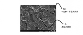
- An amorphous / amorphous carbon material 12 is dispersed on the surface of the graphite-based carbon material 10.
- the amorphous / amorphous carbon material 12 contacts the graphite-based carbon material 10 in an unfixed state and is in an electrically connected state. Further, it dissolves during charging of the battery and migrates to the negative electrode to form a tungsten compound coating 14 on the surface of the amorphous / amorphous carbon material 12.
- Nickel cobalt manganese composite hydroxide obtained by mixing and coprecipitating NiSO 4 , CoSO 4 , and MnSO 4 in an aqueous solution was fired to prepare a nickel cobalt manganese composite oxide.
- the molar ratio of the composite oxide, lithium hydroxide, tungsten oxide (WO 3 ), lithium, nickel-cobalt-manganese as a whole transition metal, and tungsten is 1.2: 1: 0.005.
- the mixture was mixed using a rough mortar.
- the positive electrode active material, WO 3 is mixed at 0.5 wt% with respect to the active material, and Li 3 PO 4 is mixed at 1 wt% with respect to the active material.
- NMP N-methyl-2-pyrrolidone
- the positive electrode mixture slurry was applied on the aluminum foil as the positive electrode current collector, and the coating film was dried to form a positive electrode mixture layer on the aluminum foil.
- the current collector on which the mixture layer was formed was cut into a predetermined size, rolled, attached with an aluminum tab, and used as a positive electrode.
- the negative electrode mixture slurry was applied to a negative electrode current collector made of copper foil and dried to form a negative electrode mixture layer.
- the current collector on which the material mixture layer was formed was cut into a predetermined size, rolled, and attached with a nickel tab to form a negative electrode.
- FIG. 2 shows SEM (scanning electron microscope) measurement results on the surface of the negative electrode plate. It can be seen that the amorphous / amorphous carbon material is uniformly dispersed with a size of 1 ⁇ m or less throughout the negative electrode plate.
- Ethylene carbonate (EC), ethyl ethyl carbonate (EMC), and dimethyl carbonate (DMC) were mixed at a volume ratio of 3: 3: 4.
- LiPF 6 was dissolved in the mixed solvent to a concentration of 1.2 mol / L to prepare a non-aqueous electrolyte.
- the wound electrode body For producing the wound electrode body, one positive electrode, one negative electrode, and one separator made of a polyethylene microporous film were used. First, the positive electrode and the negative electrode were opposed to each other with a separator interposed therebetween. Next, it was wound in a spiral shape using a cylindrical winding core. At this time, both the positive electrode current collecting tab and the negative electrode current collecting tab were arranged so as to be positioned on the outermost peripheral side in each electrode. Thereafter, the winding core was pulled out to produce a wound electrode body.
- the non-aqueous electrolyte and the wound electrode body thus prepared were inserted into an aluminum laminate outer body in a glove box under an argon atmosphere to produce a laminated non-aqueous electrolyte secondary battery. It was set as test cell A1.
- Test cell B1 was produced in the same manner as in Experimental Example 1 except that Li 3 PO 4 was not mixed with the positive electrode active material.
- Test cell B2 was prepared in the same manner as in Experimental Example 1 except that 3 PO 4 and WO 3 were not mixed.
- Test cell B3 was produced in the same manner as in Experimental Example 1, except that carbon black was not mixed during preparation of the negative electrode mixture slurry.
- Test cell B4 was produced in the same manner as in Experimental Example 2, except that carbon black was not mixed during preparation of the negative electrode mixture slurry.
- Test cell B5 was produced in the same manner as in Experimental Example 3, except that carbon black was not mixed during preparation of the negative electrode mixture slurry.
- the battery was charged to 60% of the rated capacity at a current density of 0.2 I ⁇ t (C rate) under a temperature condition of 25 ° C. and left at 75 ° C. for 22 hours. Thereafter, constant current charging was performed up to 4.1 V, and constant voltage charging was performed at a constant voltage of 4.1 V until the current density reached 0.05 I ⁇ t (C rate).
- the rated capacity of the test cell was the discharge capacity when constant current discharge was performed up to 2.5 V at a current density of 0.2 I ⁇ t (C rate) under the temperature condition of 25 ° C.
- the battery is charged at a current density of 0.2 I ⁇ t to half the rated capacity, and then ⁇ 30 ° C. Then, discharging was performed at a current density of 0.2 to 1.5 I ⁇ t for 10 seconds, and the voltage after 10 seconds was measured.
- the resistance value was calculated by plotting the measured voltage with each current density and using the value as the slope.
- Resistance reduction rates of A1 and B1 were calculated based on the resistance value of B2, and the resistance reduction rates of B3 and B4 were calculated using the following formulas based on the resistance value of B5.
- Resistance reduction rate resistance value of test cell / resistance value of test cell (reference cell)
- the test cell A1 of the experimental example (containing W in the positive electrode, WO 3 mixed, Li 3 PO 4 mixed, and carbon black (added (CB)) in the negative electrode) It can be seen that an excellent reduction in resistance can be achieved as compared with B1 and B2. This is because the presence of the W compound and the phosphoric acid compound on the positive electrode leads to the formation of an amorphous / amorphous carbon material on the negative electrode. It can be considered that a low-resistance film can be formed, and that the resistance of the battery can be reduced at low temperatures.From the above, it was confirmed that the output characteristics of the test cell A1 were improved.
- test cells B3 to B5 of the experimental example have no amorphous / amorphous carbon in the negative electrode, so that a low resistance film is not formed on the amorphous / amorphous carbon material, and the low temperature of the battery It was confirmed that the resistance reduction at the time was not sufficiently achieved.
- Example 7 A test cell was produced in the same manner as in Experimental Example 1. Thereafter, the battery was charged so as to be 60% of the rated capacity at a current density of 0.2 I ⁇ t (C rate) under a temperature condition of 25 ° C. and left at 75 ° C. for 22 hours. Next, constant current discharge was performed up to 2.5 V at a current density of 0.2 I ⁇ t (C rate).
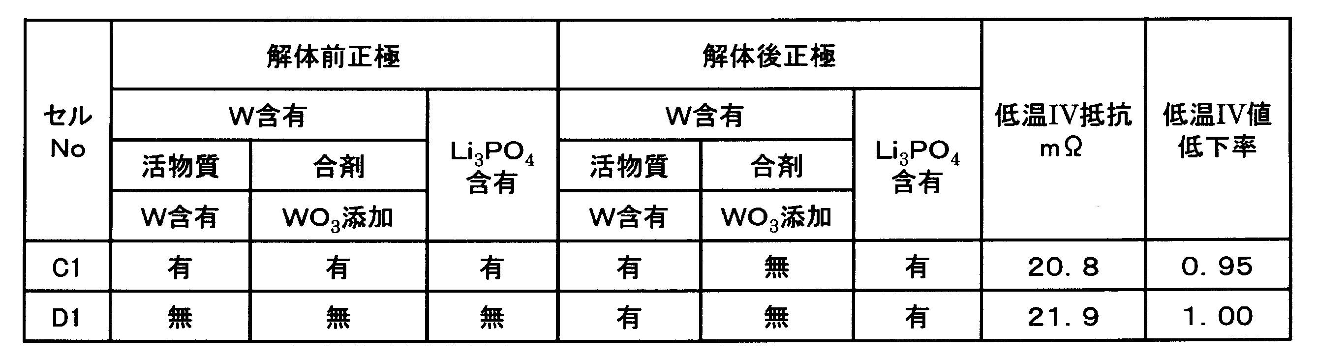
- the cell was disassembled, the negative electrode that was charged and discharged, and the positive electrode using an uncharged positive electrode active material with the same specifications as the positive electrode used in Experimental Example 1 except that WO 3 was not mixed, Similarly, a test cell C1 was prepared, and resistance measurement was performed at a low temperature.
- Example 8 A test cell D1 was prepared and resistance measurement was performed at a low temperature in the same manner as in Experimental Example 7 except that a positive electrode not mixed with W compound and Li 3 PO 4 was used as the positive electrode before disassembly.
- the low resistance of the battery can be obtained even if the positive electrode in which the W compound and the phosphate compound coexist is used. Cannot be achieved.
- the surface film is formed on the negative electrode in which the amorphous / amorphous carbon material is present mainly during the initial charging and the subsequent high-temperature standing treatment. When these treatments are carried out, the W compound and the phosphate compound are used.
- a positive electrode in which a coexisting material is formed, a low-resistance surface film is formed on the negative electrode on which the amorphous / amorphous carbon material exists, and the low resistance of the battery can be achieved.
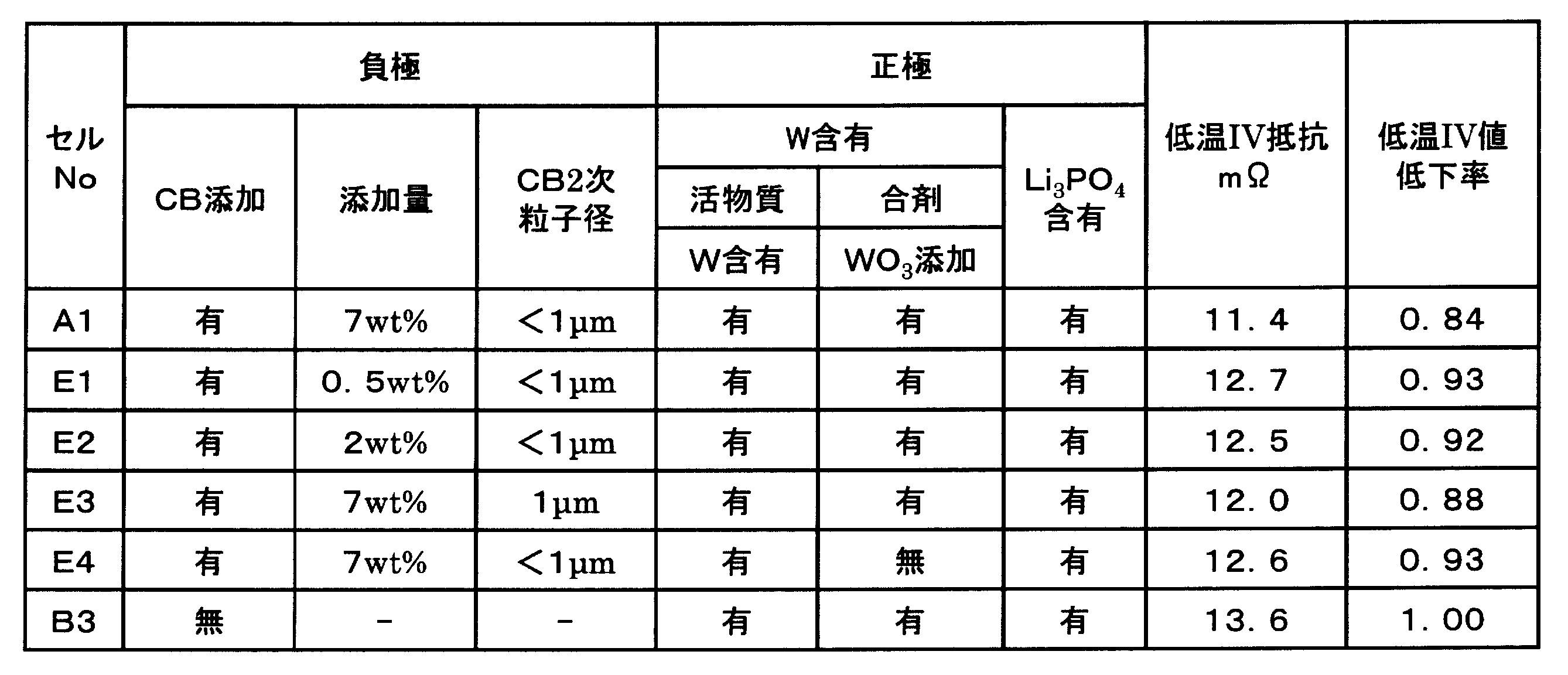
- Example 9 A test cell E1 was produced in the same manner as in Experimental Example 1 except that the amount of carbon black mixed was 0.5 wt% with respect to graphite.
- Test cell E2 was produced in the same manner as in Experimental Example 1 except that the amount of carbon black mixed was 2 wt% with respect to graphite.
- Test cell E3 was prepared in the same manner as in Experimental Example 1, except that the time required for preparation of the CB dispersion was 5 minutes.
- Test cell E4 was prepared in the same manner as in Experimental Example 1 except that WO 3 was not mixed with the positive electrode active material.
- the resistance measured by testing the cell is shown in Table 3.
- the resistance reduction rates of A1 and E1 to E4 were calculated based on the resistance value of B3.
- the amorphous / amorphous carbon material can achieve lower resistance when the amount of the mixture is larger.
- the reaction overvoltage of the Li occlusion reaction during charging can be reduced.
- the larger the amount of amorphous / amorphous carbon material mixed the smaller the secondary particle size of the amorphous / amorphous carbon material, and the more uniformly dispersed in the negative electrode, the current flowing through the negative electrode Density is uniformly relaxed and lower resistance can be achieved.
- the tungsten compound in the positive electrode mixture can be mixed with W at the time of firing the active material and lower resistance can be achieved by mixing WO 3 after firing. From this, the presence of WO 3 in the positive electrode mixture causes decomposition of WO 3 during charging, and promotes the formation of a tungsten or tungsten compound film on the amorphous / amorphous carbon material of the negative electrode. It is considered that the resistance of the negative electrode can be reduced.
- tungsten oxide to be added may be W 2 O 5 in addition to WO 3 .
Landscapes
- Chemical & Material Sciences (AREA)
- Chemical Kinetics & Catalysis (AREA)
- Electrochemistry (AREA)
- General Chemical & Material Sciences (AREA)
- Inorganic Chemistry (AREA)
- Engineering & Computer Science (AREA)
- Manufacturing & Machinery (AREA)
- Materials Engineering (AREA)
- Crystallography & Structural Chemistry (AREA)
- Composite Materials (AREA)
- Secondary Cells (AREA)
- Battery Electrode And Active Subsutance (AREA)
Abstract
Description
正極は、例えば金属箔等の正極集電体と、正極集電体上に形成された正極合剤層とで構成される。正極集電体には、アルミニウムなどの正極の電位範囲で安定な金属の箔、当該金属を表層に配置したフィルム等を用いることができる。正極合剤層は、正極活物質であるリチウム遷移金属酸化物の他に、タングステン酸化物及びリン酸化合物を含み、さらに導電剤、及び結着剤を含むことが好適である。正極は、例えば正極集電体上に正極活物質、結着剤等を含む正極合剤スラリーを塗布し、塗膜を乾燥させた後、圧延して正極合剤層を集電体の両面に形成することにより作製できる。
負極は、例えば金属箔等からなる負極集電体と、当該集電体上に形成された負極合剤層とで構成される。負極集電体には、銅等の負極の電位範囲で安定な金属の箔、当該金属を表層に配置したフィルム等を用いることができる。負極合剤層は、負極活物質の他に、結着剤を含むことが好適である。負極は、例えば負極集電体上に負極活物質、結着剤等を含む負極合剤スラリーを塗布し、塗膜を乾燥させた後、圧延して負極合剤層を集電体の両面に形成することにより作製できる。
塩であってもよい)、ポリビニルアルコール(PVA)等を用いることが好ましい。
セパレータには、イオン透過性及び絶縁性を有する多孔性シートが用いられる。多孔性シートの具体例としては、微多孔薄膜、織布、不織布等が挙げられる。セパレータの材質としては、ポリエチレン、ポリプロピレン等のオレフィン系樹脂、セルロースなどが好適である。セパレータは、セルロース繊維層及びオレフィン系樹脂等の熱可塑性樹脂繊維層を有する積層体であってもよい。
電解質は、例えば非水溶媒と、非水溶媒に溶解した電解質塩とを含む非水電解質である。非水電解質は、液体電解質(非水電解液)に限定されず、ゲル状ポリマー等を用いた固体電解質であってもよい。非水溶媒には、例えばエステル類、エーテル類、ニトリル類、ジメチルホルムアミド等のアミド類、及びこれらの2種以上の混合溶媒等を用いることができる。また、プロパンスルトン等のスルホン基含有化合物を用いてもよい。非水溶媒は、これら溶媒の水素の少なくとも一部をフッ素等のハロゲン原子で置換したハロゲン置換体を含有していてもよい。
[正極活物質の作製]
NiSO4、CoSO4、及びMnSO4を水溶液中で混合し、共沈させることで得たニッケルコバルトマンガン複合水酸化物を焼成して、ニッケルコバルトマンガン複合酸化物を作製した。次に、当該複合酸化物と水酸化リチウムと、酸化タングステン(WO3)とを、リチウムと、遷移金属全体であるニッケルコバルトマンガンと、タングステンとのモル比が1.2:1:0.005になるように、らいかい乳鉢を用いて混合した。この混合物を空気中で焼成した後、粉砕することにより、Wが含有したリチウム遷移金属酸化物に正極活物質を得た。得られた正極活物質をICPで元素分析したところ、遷移金属全体に対する各元素のモル比はNi:Co:Mn:W=47:27:26:0.5であった。
上記正極活物質と、WO3を活物質に対して0.5wt%、Li3PO4を活物質に対して1wt%混合し、これらの混合物と、カーボンブラックと、ポリフッ化ビニリデン(PVDF)とを、91:7:2の重量比で混合した。当該混合物に分散媒としてN-メチル-2-ピロリドン(NMP)を添加して混練し、正極合剤スラリーを調製した。次に、正極集電体であるアルミニウム箔上に正極合剤スラリーを塗布し、塗膜を乾燥させて、アルミニウム箔に正極合剤層を形成した。上記合剤層を形成した集電体を所定のサイズに切り出し、圧延して、アルミニウムタブを取り付け、正極とした。
結着剤であるカルボキシメチルセルロース(CMC)とカーボンブラック(CB)と水とを石川式らいかい機により30分間混合し、CB分散液を作製した。次に、作製したCB分散液と、負極活物質である黒鉛粉末と、CMCと、スチレンブタジエンゴム(SBR)と水とを混合し負極合剤スラリーを調製した。この際、黒鉛およびCB、CMC、SBRのそれぞれの質量の比が98.9:0.7:0.4となるように調製した。また、黒鉛とCBとの質量比は93:7となるようにした。
エチレンカーボネート(EC)と、エチルエチルカーボネート(EMC)と、ジメチルカーボネート(DMC)とを、3:3:4の体積比で混合した。当該混合溶媒に、LiPF6を1.2mol/Lの濃度となるように溶解させて非水電解液を調製した。
巻回電極体の作製には、上記正極を1枚、上記負極を1枚、ポリエチレン製微多孔膜からなるセパレータを1枚用いた。まず、正極と負極とをセパレータを介して互いに絶縁した状態で対向させた。次に、円柱型の巻き芯を用いて、渦巻き状に巻回した。この際、正極集電タブ、及び負極集電タブは、共にそれぞれの電極内における最外周側に位置するように配置した。その後、巻き芯を引き抜いて巻回電極体を作製した。
正極活物質にLi3PO4を混合しなかった以外は実験例1と同様にして試験セルB1を作製した。
正極活物質としてWO3を混合させずに焼成を実施して、全遷移金属に対する各遷移金属の比率がNi:Co:Mn=35:35:30であるリチウム遷移金属酸化物を使用し、Li3PO4、WO3を混合しなかった以外は実験例1と同様にして試験セルB2を作製した。
負極合剤スラリーを調製時にカーボンブラックを混合しなかった以外は、実験例1と同様にして試験セルB3を作製した。
負極合剤スラリーを調製時にカーボンブラックを混合しなかった以外は、実験例2と同様にして試験セルB4を作製した。
負極合剤スラリーを調製時にカーボンブラックを混合しなかった以外は、実験例3と同様にして試験セルB5を作製した。
試験セルA1に用いた負極を表面からSEMを用いて観察し、不定形/非晶質炭素のサイズを測定した。SEMによる粒子径の観察は、任意の10μm×8μmの領域を観察し、不定形/非晶質炭素の粒子径を測定した。この領域内の粒子の90%以上がある粒径以下の際、この粒径を二次粒子径とした。
25℃の温度条件において、0.2I・t(Cレート)の電流密度で定格容量の60%となるように充電を行い、75℃で22時間放置した。その後、4.1Vまで定電流充電を行い、4.1Vの定電圧で電流密度が0.05I・t(Cレート)になるまで定電圧充電を行った。なお、25℃の温度条件において、0.2I・t(Cレート)の電流密度で2.5Vまで定電流放電を行ったときの放電容量を試験セルの定格容量とした。
とした後、0.2~1.5I・tの電流密度で10秒間放電して、10秒後の電圧を測定した。
抵抗低下率=試験セルの抵抗値/試験セル(基準セル)の抵抗値

が十分に達成されていないことが確認された。
実験例1と同様にして試験セルを作製した。その後、25℃の温度条件において、0.2I・t(Cレート)の電流密度で定格容量の60%となるように充電を行い、75℃で22時間放置した。次に0.2I・t(Cレート)の電流密度で2.5Vまで定電流放電を行った。
解体前の正極として、W化合物、およびLi3PO4を混合していない正極を使用した
以外は実験例7と同様にして試験セルD1を作製して低温での抵抗測定を実施した。
なお、D1の抵抗値を基準にしてC1の抵抗低下率を算出した。
カーボンブラックの混合量を黒鉛に対して0.5wt%としたこと以外は、実験例1と同様にして試験セルE1を作製した。
カーボンブラックの混合量を黒鉛に対して2wt%としたこと以外は、実験例1と同様にして試験セルE2を作製した。
CB分散液の作製時にらいかい時間を5分間とした以外は、実験例1と同様にして試験セルE3を作製した。
正極活物質にWO3を混合しなかった以外は実験例1と同様にして試験セルE4を作製した。
なお、B3の抵抗値を基準にしてA1とE1~E4の抵抗低下率を算出した。
Claims (7)
- 正極板と負極板がセパレータを介して積層された構造を有する電極体を備えた非水電解質二次電池であって、
前記正極板は、正極活物質としてタングステンを含有するリチウム遷移金属酸化物を含み、かつ、リン酸化合物を含み、
前記負極板は、負極活物質として黒鉛系炭素材、及び前記黒鉛系炭素材に対して固着していない不定形/非晶質炭素材を含み、
前記不定形/非晶質炭素材の表面被膜に、タングステン又はタングステン化合物を含む、非水電解質二次電池。 - 前記正極板は、さらにタングステン酸化物を含有する、請求項1に記載の非水電解質二次電池。
- 前記タングステン酸化物は、WO3である、請求項2に記載の非水電解質二次電池。
- 前記不定形/非晶質炭素材は、前記黒鉛系炭素材に対して分散して存在する、請求項1~3のいずれかに記載の非水電解質二次電池。
- 前記不定形/非晶質炭素材は、カーボンブラックである、請求項1~4のいずれかに記載の非水電解質二次電池。
- 前記不定形/非晶質炭素材の含有率は、前記黒鉛系炭素材に対して0.5重量%以上である、請求項1~5のいずれかに記載の非水電解質二次電池。
- 前記不定形/非晶質炭素材の二次粒子径は、1μm以下である、請求項1~6のいずれかに記載の非水電解質二次電池。
Priority Applications (3)
| Application Number | Priority Date | Filing Date | Title |
|---|---|---|---|
| CN201680011844.3A CN107251306B (zh) | 2015-02-27 | 2016-02-18 | 非水电解质二次电池 |
| US15/551,843 US10297826B2 (en) | 2015-02-27 | 2016-02-18 | Nonaqueous electrolyte secondary battery |
| JP2017501918A JP6588079B2 (ja) | 2015-02-27 | 2016-02-18 | 非水電解質二次電池 |
Applications Claiming Priority (2)
| Application Number | Priority Date | Filing Date | Title |
|---|---|---|---|
| JP2015038191 | 2015-02-27 | ||
| JP2015-038191 | 2015-02-27 |
Publications (1)
| Publication Number | Publication Date |
|---|---|
| WO2016136211A1 true WO2016136211A1 (ja) | 2016-09-01 |
Family
ID=56788098
Family Applications (1)
| Application Number | Title | Priority Date | Filing Date |
|---|---|---|---|
| PCT/JP2016/000864 Ceased WO2016136211A1 (ja) | 2015-02-27 | 2016-02-18 | 非水電解質二次電池 |
Country Status (4)
| Country | Link |
|---|---|
| US (1) | US10297826B2 (ja) |
| JP (1) | JP6588079B2 (ja) |
| CN (1) | CN107251306B (ja) |
| WO (1) | WO2016136211A1 (ja) |
Cited By (9)
| Publication number | Priority date | Publication date | Assignee | Title |
|---|---|---|---|---|
| WO2017110089A1 (ja) * | 2015-12-25 | 2017-06-29 | パナソニックIpマネジメント株式会社 | 非水電解質二次電池 |
| WO2018030176A1 (ja) * | 2016-08-09 | 2018-02-15 | パナソニックIpマネジメント株式会社 | 非水電解質二次電池 |
| KR20180082006A (ko) * | 2017-01-09 | 2018-07-18 | 한양대학교 산학협력단 | 급속 충방전이 가능한 탄소계 음극 활물질, 이의 제조방법 및 이를 이용한 리튬 이차전지용 음극 |
| JP2018190501A (ja) * | 2017-04-28 | 2018-11-29 | トヨタ自動車株式会社 | リチウムイオン二次電池 |
| JP2019050155A (ja) * | 2017-09-11 | 2019-03-28 | トヨタ自動車株式会社 | 非水電解液二次電池 |
| JP2021018897A (ja) * | 2019-07-18 | 2021-02-15 | トヨタ自動車株式会社 | 非水電解質二次電池 |
| WO2022168994A1 (ja) * | 2021-02-05 | 2022-08-11 | 株式会社村田製作所 | 二次電池 |
| WO2024029333A1 (ja) * | 2022-08-01 | 2024-02-08 | 株式会社Gsユアサ | 非水電解質蓄電素子 |
| WO2025192247A1 (ja) * | 2024-03-13 | 2025-09-18 | 株式会社Gsユアサ | 非水電解液蓄電素子 |
Families Citing this family (4)
| Publication number | Priority date | Publication date | Assignee | Title |
|---|---|---|---|---|
| US10529978B2 (en) * | 2015-03-30 | 2020-01-07 | Sanyo Electric Co., Ltd. | Nonaqueous electrolyte secondary battery |
| JP7032973B2 (ja) * | 2018-03-29 | 2022-03-09 | 太陽誘電株式会社 | 全固体電池およびその製造方法 |
| JP7125238B2 (ja) * | 2019-07-18 | 2022-08-24 | トヨタ自動車株式会社 | 非水電解質二次電池 |
| WO2023224070A1 (ja) * | 2022-05-20 | 2023-11-23 | 株式会社Gsユアサ | 非水電解質蓄電素子 |
Citations (5)
| Publication number | Priority date | Publication date | Assignee | Title |
|---|---|---|---|---|
| JP2007335331A (ja) * | 2006-06-16 | 2007-12-27 | Sony Corp | 正極活物質およびその製造方法、正極およびその製造方法ならびに二次電池 |
| JP2008016235A (ja) * | 2006-07-03 | 2008-01-24 | Sony Corp | 正極活物質およびその製造方法、並びに非水電解質二次電池 |
| JP2009123463A (ja) * | 2007-11-14 | 2009-06-04 | Sony Corp | リチウムイオン二次電池用正極、その製造方法及びリチウムイオン二次電池 |
| JP2012038534A (ja) * | 2010-08-06 | 2012-02-23 | Hitachi Ltd | リチウム二次電池用正極材料,リチウム二次電池及びそれを用いた二次電池モジュール |
| JP2015210891A (ja) * | 2014-04-24 | 2015-11-24 | トヨタ自動車株式会社 | 非水電解質二次電池 |
Family Cites Families (11)
| Publication number | Priority date | Publication date | Assignee | Title |
|---|---|---|---|---|
| US7179565B2 (en) * | 2001-12-06 | 2007-02-20 | Matsushita Electric Industrial Co., Ltd. | Lithium ion secondary cell |
| JP2003346804A (ja) | 2002-05-28 | 2003-12-05 | Sony Corp | 負極材料、非水電解質電池及び負極材料の製造方法 |
| US8080335B2 (en) * | 2006-06-09 | 2011-12-20 | Canon Kabushiki Kaisha | Powder material, electrode structure using the powder material, and energy storage device having the electrode structure |
| US8911903B2 (en) | 2006-07-03 | 2014-12-16 | Sony Corporation | Cathode active material, its manufacturing method, and non-aqueous electrolyte secondary battery |
| JP5589751B2 (ja) * | 2010-03-02 | 2014-09-17 | ソニー株式会社 | 非水電解質電池および非水電解質 |
| FR2961634B1 (fr) * | 2010-06-17 | 2013-02-15 | Centre Nat Rech Scient | Procede pour l'elaboration d'une batterie au lithium ou au sodium |
| WO2013094668A1 (ja) * | 2011-12-22 | 2013-06-27 | 三洋電機株式会社 | 非水電解質二次電池 |
| CN104254937B (zh) * | 2012-03-30 | 2016-07-20 | 三洋电机株式会社 | 非水电解质二次电池用正极及非水电解质二次电池 |
| JP6066306B2 (ja) * | 2012-07-04 | 2017-01-25 | 株式会社Gsユアサ | 非水電解質二次電池及び非水電解質二次電池の製造方法 |
| CN102903930B (zh) * | 2012-10-23 | 2016-06-08 | 中国科学院过程工程研究所 | 一种锂离子二次电池及其制备方法 |
| WO2014128903A1 (ja) | 2013-02-22 | 2014-08-28 | 株式会社 日立製作所 | リチウムイオン二次電池 |
-
2016
- 2016-02-18 CN CN201680011844.3A patent/CN107251306B/zh active Active
- 2016-02-18 WO PCT/JP2016/000864 patent/WO2016136211A1/ja not_active Ceased
- 2016-02-18 US US15/551,843 patent/US10297826B2/en active Active
- 2016-02-18 JP JP2017501918A patent/JP6588079B2/ja active Active
Patent Citations (5)
| Publication number | Priority date | Publication date | Assignee | Title |
|---|---|---|---|---|
| JP2007335331A (ja) * | 2006-06-16 | 2007-12-27 | Sony Corp | 正極活物質およびその製造方法、正極およびその製造方法ならびに二次電池 |
| JP2008016235A (ja) * | 2006-07-03 | 2008-01-24 | Sony Corp | 正極活物質およびその製造方法、並びに非水電解質二次電池 |
| JP2009123463A (ja) * | 2007-11-14 | 2009-06-04 | Sony Corp | リチウムイオン二次電池用正極、その製造方法及びリチウムイオン二次電池 |
| JP2012038534A (ja) * | 2010-08-06 | 2012-02-23 | Hitachi Ltd | リチウム二次電池用正極材料,リチウム二次電池及びそれを用いた二次電池モジュール |
| JP2015210891A (ja) * | 2014-04-24 | 2015-11-24 | トヨタ自動車株式会社 | 非水電解質二次電池 |
Cited By (14)
| Publication number | Priority date | Publication date | Assignee | Title |
|---|---|---|---|---|
| WO2017110089A1 (ja) * | 2015-12-25 | 2017-06-29 | パナソニックIpマネジメント株式会社 | 非水電解質二次電池 |
| JPWO2017110089A1 (ja) * | 2015-12-25 | 2018-10-18 | パナソニックIpマネジメント株式会社 | 非水電解質二次電池 |
| JPWO2018030176A1 (ja) * | 2016-08-09 | 2019-06-06 | パナソニックIpマネジメント株式会社 | 非水電解質二次電池 |
| WO2018030176A1 (ja) * | 2016-08-09 | 2018-02-15 | パナソニックIpマネジメント株式会社 | 非水電解質二次電池 |
| US11024837B2 (en) | 2016-08-09 | 2021-06-01 | Panasonic Intellectual Property Management Co., Ltd. | Nonaqueous electrolyte secondary battery |
| KR101905703B1 (ko) * | 2017-01-09 | 2018-10-08 | 한양대학교 산학협력단 | 급속 충방전이 가능한 탄소계 음극 활물질, 이의 제조방법 및 이를 이용한 리튬 이차전지용 음극 |
| KR20180082006A (ko) * | 2017-01-09 | 2018-07-18 | 한양대학교 산학협력단 | 급속 충방전이 가능한 탄소계 음극 활물질, 이의 제조방법 및 이를 이용한 리튬 이차전지용 음극 |
| JP2018190501A (ja) * | 2017-04-28 | 2018-11-29 | トヨタ自動車株式会社 | リチウムイオン二次電池 |
| JP2019050155A (ja) * | 2017-09-11 | 2019-03-28 | トヨタ自動車株式会社 | 非水電解液二次電池 |
| JP2021018897A (ja) * | 2019-07-18 | 2021-02-15 | トヨタ自動車株式会社 | 非水電解質二次電池 |
| JP7068238B2 (ja) | 2019-07-18 | 2022-05-16 | トヨタ自動車株式会社 | 非水電解質二次電池 |
| WO2022168994A1 (ja) * | 2021-02-05 | 2022-08-11 | 株式会社村田製作所 | 二次電池 |
| WO2024029333A1 (ja) * | 2022-08-01 | 2024-02-08 | 株式会社Gsユアサ | 非水電解質蓄電素子 |
| WO2025192247A1 (ja) * | 2024-03-13 | 2025-09-18 | 株式会社Gsユアサ | 非水電解液蓄電素子 |
Also Published As
| Publication number | Publication date |
|---|---|
| JP6588079B2 (ja) | 2019-10-09 |
| CN107251306B (zh) | 2019-08-06 |
| US10297826B2 (en) | 2019-05-21 |
| JPWO2016136211A1 (ja) | 2017-12-07 |
| US20180040885A1 (en) | 2018-02-08 |
| CN107251306A (zh) | 2017-10-13 |
Similar Documents
| Publication | Publication Date | Title |
|---|---|---|
| JP6588079B2 (ja) | 非水電解質二次電池 | |
| CN107112499B (zh) | 非水电解质二次电池用负极和非水电解质二次电池 | |
| US10263252B2 (en) | Negative electrode for non-aqueous electrolyte secondary battery, and non-aqueous electrolyte secondary battery | |
| JP6018588B2 (ja) | 出力向上のためのリチウム二次電池用正極材及びこれを含むリチウム二次電池 | |
| JP6728134B2 (ja) | 非水電解質二次電池 | |
| CN107851839B (zh) | 非水电解质二次电池 | |
| CN107251302B (zh) | 非水电解质二次电池 | |
| JP2014518000A (ja) | 出力向上のためのリチウム二次電池の複合電極用活物質およびこれを含むリチウム二次電池 | |
| CN110088970B (zh) | 非水电解质二次电池 | |
| KR102953598B1 (ko) | 양극 첨가제의 제조방법, 양극 첨가제, 이를 포함하는 양극 및 리튬 이차전지 | |
| CN115004403B (zh) | 非水电解质二次电池用正极和非水电解质二次电池 | |
| CN106716701A (zh) | 非水电解质二次电池 | |
| JP2018006331A (ja) | 非水電解質二次電池用負極材料及びその製造方法 | |
| WO2017110080A1 (ja) | 非水電解質二次電池 | |
| WO2017110089A1 (ja) | 非水電解質二次電池 | |
| KR20230115234A (ko) | 리튬 이차전지용 전해액 및 이를 포함하는 리튬 이차전지 | |
| JP6154467B2 (ja) | リチウム二次電池 | |
| CN115699394A (zh) | 非水电解质二次电池 | |
| JP7724466B2 (ja) | 非水電解質二次電池および非水電解質二次電池用の負極合剤の製造方法 | |
| JPWO2015046495A1 (ja) | リチウムイオン二次電池の正極材料 | |
| WO2023054003A1 (ja) | 二次電池用電極および二次電池 | |
| WO2023276526A1 (ja) | 非水電解質二次電池 | |
| CN114788041A (zh) | 非水电解质二次电池用正极和非水电解质二次电池 |
Legal Events
| Date | Code | Title | Description |
|---|---|---|---|
| 121 | Ep: the epo has been informed by wipo that ep was designated in this application |
Ref document number: 16754962 Country of ref document: EP Kind code of ref document: A1 |
|
| ENP | Entry into the national phase |
Ref document number: 2017501918 Country of ref document: JP Kind code of ref document: A |
|
| WWE | Wipo information: entry into national phase |
Ref document number: 15551843 Country of ref document: US |
|
| NENP | Non-entry into the national phase |
Ref country code: DE |
|
| 122 | Ep: pct application non-entry in european phase |
Ref document number: 16754962 Country of ref document: EP Kind code of ref document: A1 |