WO2016136072A1 - トルクコンバータ - Google Patents
トルクコンバータ Download PDFInfo
- Publication number
- WO2016136072A1 WO2016136072A1 PCT/JP2015/084032 JP2015084032W WO2016136072A1 WO 2016136072 A1 WO2016136072 A1 WO 2016136072A1 JP 2015084032 W JP2015084032 W JP 2015084032W WO 2016136072 A1 WO2016136072 A1 WO 2016136072A1
- Authority
- WO
- WIPO (PCT)
- Prior art keywords
- screwing
- torque converter
- impeller
- front cover
- connection structure
- Prior art date
- Legal status (The legal status is an assumption and is not a legal conclusion. Google has not performed a legal analysis and makes no representation as to the accuracy of the status listed.)
- Ceased
Links
Images






Classifications
-
- F—MECHANICAL ENGINEERING; LIGHTING; HEATING; WEAPONS; BLASTING
- F16—ENGINEERING ELEMENTS AND UNITS; GENERAL MEASURES FOR PRODUCING AND MAINTAINING EFFECTIVE FUNCTIONING OF MACHINES OR INSTALLATIONS; THERMAL INSULATION IN GENERAL
- F16B—DEVICES FOR FASTENING OR SECURING CONSTRUCTIONAL ELEMENTS OR MACHINE PARTS TOGETHER, e.g. NAILS, BOLTS, CIRCLIPS, CLAMPS, CLIPS OR WEDGES; JOINTS OR JOINTING
- F16B5/00—Joining sheets or plates, e.g. panels, to one another or to strips or bars parallel to them
- F16B5/02—Joining sheets or plates, e.g. panels, to one another or to strips or bars parallel to them by means of fastening members using screw-thread
-
- F—MECHANICAL ENGINEERING; LIGHTING; HEATING; WEAPONS; BLASTING
- F16—ENGINEERING ELEMENTS AND UNITS; GENERAL MEASURES FOR PRODUCING AND MAINTAINING EFFECTIVE FUNCTIONING OF MACHINES OR INSTALLATIONS; THERMAL INSULATION IN GENERAL
- F16H—GEARING
- F16H41/00—Rotary fluid gearing of the hydrokinetic type
- F16H41/24—Details
Definitions
- the present invention relates to a torque converter.
- a conventional torque converter mainly includes a front cover and three types of impellers (impeller, turbine, and stator) (see Patent Document 1).
- the impeller has an impeller shell, a plurality of impeller blades mounted on the inner side of the impeller shell, and an impeller hub held on the inner peripheral end of the impeller shell.
- the turbine includes a turbine shell and a plurality of turbine blades attached to the turbine shell.
- the front cover and the impeller shell are connected to each other via a screw structure.
- the present invention has been made in view of the above problems, and an object of the present invention is to provide a torque converter that can reliably connect the first member and the second member.
- a torque converter connects a rotatable first member, a second member that forms a space that can be filled with a working fluid together with the first member, and the first member and the second member. And a connecting structure to be provided.
- the connection structure has a first threaded portion, a first engaging portion, a second threaded portion, and a second engaging portion.
- the first screwing portion is provided on one of the first member and the second member.
- the first engaging portion is provided on either the first member or the second member in line with the first screwing portion.
- the second screwing portion can be screwed into the first screwing portion and is provided on the other of the first member and the second member.
- the second engaging portion can be engaged with the first engaging portion, and is provided on the other of the first member and the second member.
- connection structure connects the first member and the second member.
- the first screwing part and the second screwing part are screwed together, and the first engaging part and the second engaging part are engaged. That is, not only the first screwing portion and the second screwing portion are screwed but also the first engaging portion and the second engaging portion are further engaged, so that the first member and the second member are securely connected. Can be linked to.
- the torque converter according to another aspect of the present invention is preferably configured as follows.
- the connection structure further includes a first contact portion and a second contact portion.
- the first contact portion is provided on either the first member or the second member.
- the second contact portion is provided on the other of the first member and the second member. The first member and the second member are positioned relative to each other by the contact between the second contact portion and the first contact portion.
- connection structure in the torque converter, the first member and the second member are positioned relative to each other when the second contact portion and the first contact portion contact each other. Thereby, connection and positioning of a 1st member and a 2nd member can be performed reliably.
- the torque converter according to another aspect of the present invention is preferably configured as follows.
- An adhesive is disposed between at least one of the first screwed portion and the second screwed portion and between the first engaging portion and the second engaging portion.
- the adhesive is disposed between at least one of the first and second screwing portions and between the first and second engaging portions.
- the first member and the second member can be more reliably connected.
- the torque converter according to another aspect of the present invention is preferably configured as follows.
- the connection structure further includes a first groove for arranging the adhesive.
- the first groove portion is provided in at least one of the first engagement portion and the second engagement portion.
- the adhesive is disposed in the first groove portion, the first engagement portion and the second engagement portion can be stably and reliably bonded. That is, the first member and the second member can be connected stably and reliably.
- the torque converter according to another aspect of the present invention is preferably configured as follows.
- the connection structure further includes a second groove portion for arranging the adhesive.
- the second groove is provided in at least one of the vicinity of the first screwing portion and the vicinity of the second screwing portion.
- the adhesive is disposed in the second groove portion, the screwing of the first screwing portion and the second screwing portion can be stably and reliably held. That is, the first member and the second member can be connected stably and reliably.
- the torque converter according to another aspect of the present invention is preferably configured as follows.
- the first engaging portion has a first inclined portion that is inclined in a direction along the rotation axis of the first member.
- the second engaging portion has a second inclined portion that can come into contact with the first inclined portion.
- the first inclined portion of the first engaging portion and the second inclined portion of the second engaging portion can contact each other, so that the first screwing portion and the second screwing portion are screwed together.
- the first engaging portion and the second engaging portion can be smoothly engaged.
- the torque converter according to another aspect of the present invention is preferably configured as follows.
- the first engagement portion and the second engagement portion are formed in a rotation direction with reference to the rotation axis of the first member.
- One of the first engaging portion and the second engaging portion is disposed on the inner peripheral side of the other of the first engaging portion and the second engaging portion.
- the outer diameter of one of the first engaging portion and the second engaging portion is larger than the inner diameter of the other of the first engaging portion and the second engaging portion.
- the first engaging portion since the outer diameter of the first engaging portion (or the second engaging portion) is larger than the inner diameter of the second engaging portion (or the first engaging portion), the first engaging portion and the second engaging portion.
- the engaged state of the engaging portion can be reliably maintained.
- the torque converter according to another aspect of the present invention is preferably configured as follows. At least one of the screw bottom portion of the first screwing portion aligned in the direction along the rotation axis of the first member and the screw bottom portion of the second screwing portion aligned in the direction along the rotation axis of the first member is the first It is inclined in a direction along the rotation axis of one member.
- At least one of the screw bottom portion of the first screwing portion arranged in the direction along the rotation axis of the first member and the screw bottom portion of the second screwing portion arranged in the direction along the rotation axis of the first member By tilting one of them as described above, the first screwing portion and the second screwing portion can be smoothly screwed together.
- the torque converter according to another aspect of the present invention is preferably configured as follows.
- the first engaging portion has a first inclined portion that is inclined in a direction along the rotation axis of the first member.
- the second engaging portion has a second inclined portion that can come into contact with the first inclined portion.
- the inclination angle of at least one of the screw bottom portion of the first screwing portion and the screw bottom portion of the second screwing portion that is inclined in the direction along the rotation axis of the first member is the first inclination portion and the second inclination angle. It is smaller than the inclination angle of at least one of the parts.
- the torque converter according to another aspect of the present invention is preferably configured as follows.
- the first member and the second member are disposed between the engine and the transmission.
- the first member is disposed on the transmission side
- the second member is disposed on the engine side.
- the direction in which the second threaded portion is screwed into the first threaded portion is the same as the rotational direction of the engine. Since the direction in which the two screwing portions are screwed into the first screwing portion and the rotation direction of the engine are set to be the same, even if the first member and the second member are rotated by the engine, the first It is possible to reliably prevent loosening of the screwing portion and the second screwing portion.
- the torque converter according to another aspect of the present invention is preferably configured as follows.
- the connection structure further includes a fixing structure provided on at least one of the first member and the second member for fixing the connection between the first member and the second member.
- connection structure further includes a fixing structure, the connection between the first member and the second member can be more reliably fixed.
- the torque converter according to another aspect of the present invention is preferably configured as follows.
- the fixing structure has a welded portion for fixing the connection between the first member and the second member.
- connection of the first member and the second member can be more reliably fixed by the welded portion.
- the torque converter according to another aspect of the present invention is preferably configured as follows.
- the welded portion fixes the connection between the first member and the second member via the holding member.
- connection of the first member and the second member can be more reliably fixed by the welded portion via the holding member.
- the torque converter according to another aspect of the present invention is preferably configured as follows.
- the fixing structure has a caulking portion provided on at least one of the first member and the second member.
- the connection of the first member and the second member is fixed by caulking and fixing the caulking portion to at least one of the first member and the second member.
- connection of the first member and the second member can be easily and reliably fixed by the caulking portion.
- the torque converter according to another aspect of the present invention is preferably configured as follows.
- the fixing structure includes a pair of groove portions that are provided on the first member and the second member and can face each other, and a ring member that is disposed in the pair of groove portions and prevents the first member and the second member from coming off from each other.
- connection of the first member and the second member can be easily and reliably fixed by the ring member disposed in the pair of grooves.
- the torque converter according to another aspect of the present invention is preferably configured as follows.
- the first member is a front cover.
- the second member is an impeller.
- the connection structure connects the opening of the front cover and the opening of the impeller to each other.
- the front cover and the impeller can be reliably connected by the connecting structure.
- the torque converter according to another aspect of the present invention is preferably configured as follows.
- the first member is an impeller shell.
- the second member is a first boss member connected to the impeller shell.
- the connection structure connects the first hole portion of the impeller shell and the end portion of the first boss member to each other.
- the impeller shell and the first boss portion connected to the impeller can be reliably connected by the connecting structure.
- the torque converter according to another aspect of the present invention is preferably configured as follows.
- the first member is a front cover body.
- the second member is a second boss member connected to the front cover body.
- the connection structure connects the second hole portion of the front cover body and the end portion of the second boss member to each other.
- the front cover main body and the second boss portion connected to the front cover main body can be reliably connected by the connecting structure.
- the torque converter of the present invention can reliably connect the first member and the second member.
- 1 is a longitudinal sectional view of a torque converter according to a first embodiment of the present invention.
- the expanded sectional view of the 1st connection structure in other embodiments of a 1st embodiment.
- the expanded sectional view of the 1st connection structure in other embodiments of a 1st embodiment.
- the expanded sectional view of the 1st connection structure in other embodiments of a 1st embodiment.
- the expanded sectional view of the 1st connection structure in other embodiments of a 1st embodiment.
- the longitudinal cross-sectional view of the torque converter which concerns on 2nd Embodiment of this invention.
- the expanded sectional view of the 2nd connection structure in other embodiments of a 2nd embodiment.
- the longitudinal cross-sectional view of the torque converter which concerns on 3rd Embodiment of this invention.
- the expanded sectional view of the 2nd connection structure in other embodiments of a 3rd embodiment.
- the expanded sectional view of the 4th connection structure in the torque converter concerning a 4th embodiment of the present invention.
- the expanded sectional view of the 4th connection structure in other embodiments of the 4th embodiment of the present invention (the 1).
- the expanded sectional view of the 4th connection structure in other embodiments of the 4th embodiment of the present invention (the 2).
- the expanded sectional view (the 3) of the 4th connection structure in other embodiments of a 4th embodiment of the present invention.
- FIG. 1 shows a torque converter 1 according to a first embodiment of the present invention.
- OO is the rotating shaft of the torque converter 1.
- An engine (not shown) is arranged on the left side of FIG. 1, and a transmission (not shown) is arranged on the right side of FIG.
- the rotation axis O of the torque converter 1 may be expressed as the rotation axis O of the impeller 3.
- the torque converter 1 is a mechanism for transmitting torque from the crankshaft 50 on the engine side to the main drive shaft 60 of the transmission.
- the torque converter 1 mainly includes a front cover 2 (an example of a second member), an impeller 3 (an example of a first member), a turbine 4, a stator 5, a lockup device 9, and a first connection structure 10. (An example of a connection structure).
- the front cover 2 is connected to the crankshaft 40 on the engine side via a flexible plate 41.
- the front cover 2 includes a front cover main body 21 and a front boss 23.
- the front cover body 21 and the impeller 3 form a hydraulic oil chamber that can be filled with hydraulic oil.
- the front cover body 21 is connected to the flexible plate 41 via the nut portion 25.
- the nut portion 25 has a nut main body 25a and a connecting portion 25b formed integrally with the nut main body 25a.
- a flexible plate 41 is attached to the nut body 25a via bolts 24.
- the connection part 25b is a male screw part, for example.
- the connecting portion 25 b (male screw portion) is screwed into the female screw portion 22 provided on the front cover main body 21.
- the flexible plate 41 is screwed to the nut main body 25a by the bolt 24 in a state where the connecting portion 25b (male screw portion) is screwed to the female screw portion 22 of the front cover main body 21. Thereby, the flexible plate 41 is fixed to the front cover 2.
- the nut portion 25 is attached to the front cover main body 21 by screwing the nut portion 25 (connecting portion 25b) to the front cover main body 21 (female screw portion 22) has been shown.
- the nut portion 25 (nut body 25a) may be welded to the front cover body 21.
- the front boss 23 is provided on the front cover main body 21.
- the front boss 23 protrudes from the front cover main body 21 toward the engine side, and positions the crankshaft 40 on the engine side.
- the front boss 23 is fixed to the front cover body 21 by welding, for example.
- the impeller 3 is coupled to the front cover 2 via a first coupling structure 10 (described later).
- the impeller 3 mainly includes an impeller shell 31, a plurality of impeller blades 32, and an impeller hub 33.
- the impeller shell 31 is connected to the front cover 2 by the first connection structure 10.
- the plurality of impeller blades 32 are held inside the impeller shell 31.
- the impeller hub 33 is provided on the inner peripheral side of the impeller shell 31 (the rotation shaft O side of the impeller 3).
- the impeller hub 33 is fixed to the impeller shell 31 by welding, for example.
- the turbine 4 is disposed so as to face the impeller shell 31 in the hydraulic oil chamber.
- the turbine 4 mainly has a turbine shell 4a and a plurality of turbine blades 4b held by the turbine shell 4a.
- the inner peripheral portion of the turbine shell 4 a is held on the flange portion of the turbine hub 8 by a plurality of rivets.
- a spline hole is formed in the inner peripheral portion of the turbine hub 8 to be connected to the main drive shaft 60 extending from the transmission side.
- the stator 5 is disposed between the impeller 3 and the turbine 4.
- the stator 5 is held on the stator shaft 70 via a one-way clutch.
- the lockup device 9 is a mechanism for mechanically connecting the front cover 2 and the turbine 4.
- the lockup device 9 is disposed between the front cover 2 and the turbine 4.
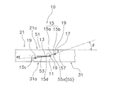
- FIG. 2A is a partially enlarged view of the first connection structure 10 of FIG.
- each part is schematically expressed by enlargement or the like.
- the first connecting structure 10 is for connecting the impeller 3 and the front cover 2. As shown in FIG. Specifically, the first connection structure 10 connects the outer peripheral portion 31a of the impeller shell 31 and the outer peripheral portion 21a of the front cover body 21 to each other. More specifically, the first connection structure 10 connects the outer peripheral portion 31a on the opening side of the impeller shell 31 and the outer peripheral portion 21a on the opening side of the front cover body 21 to each other.
- a hydraulic oil chamber an example of a space
- the first connection structure 10 is provided on the outer peripheral portion 31 a on the opening side of the impeller shell 31 and the outer peripheral portion 21 a on the opening side of the front cover main body 21.
- the first connection structure 10 provided on the outer peripheral portion 31a on the opening side of the impeller shell 31 includes a first main body portion 11, a first screwing portion 13, a first engaging portion 15, And a first abutting portion 17.
- the first screwing portion 13, the first engaging portion 15, and the first contact portion 17 are arranged side by side along the rotation axis O of the impeller 3.
- the first main body portion 11 is formed to protrude outward from the outer peripheral portion of the impeller shell 31.
- the 1st main-body part 11 is formed in the substantially cylindrical shape.
- the first main body portion 11 is disposed inside the outer peripheral portion on the opening side of the front cover 2. That is, the first main body 11 is disposed on the inner peripheral side of the second main body 51 (described later).
- the first screwing portion 13 is formed integrally with the outer peripheral portion of the first main body portion 11. Specifically, the first screwing portion 13 is formed integrally with the outer peripheral portion of the first main body portion 11 on the opening side.
- the first screwing portion 13 can be screwed into a second screwing portion 53 (described later) of the front cover 2.
- the first screwing portion 13 and the first screwing portion 13 are arranged such that the direction in which the first screwing portion 13 is screwed into the second screwing portion 53 is opposite to the rotational direction of the engine. Two screwing portions 53 are formed.
- the first screwing portion 13 is, for example, a male screw portion.
- the outer diameter (thread diameter) of the first screwing portion 13 is smaller than the outer diameter of the outer peripheral portion of the impeller shell 31.
- the first threaded portion 13 is formed so that the screw bottom portion is inclined in a direction along the rotation axis O of the impeller 3.
- the screw bottoms of the first threaded portions 13 aligned in the direction along the rotation axis O of the impeller 3 are arranged in the direction along the rotation axis O of the impeller 3, that is, the direction in which the first main body portion 11 protrudes. Inclined to approach O. In other words, the valley diameter of the thread groove gradually decreases in the direction in which the first main body portion 11 protrudes (the front end portion of the first main body portion 11).
- the inclination angle ⁇ of the screw bottom portion of the first screwing portion 13 is smaller than the inclination angle ⁇ of a first inclination portion 15a (described later) of the first engagement portion 15.
- the inclination angle of the screw bottom portion of the first screwing portion 13 is set to 3 degrees, for example.
- the thread on the distal end side of the first threaded portion 13 (or the thread on the distal end side of the second threaded portion 53) is a thread groove (or first threaded portion on the distal end side of the second threaded portion 53). 13 can be screwed into the thread groove 13 on the tip side.
- the first engaging portion 15 can be engaged with a second engaging portion 55 (described later) of the front cover 2. Specifically, the first engaging portion 15 can be engaged with the second engaging portion 55 in a state where at least a part of the first screwing portion 13 and the second screwing portion 53 are screwed together.
- the first engaging portion 15 is formed integrally with the outer peripheral portion of the first main body portion 11. Specifically, the first engagement portion 15 is configured so that the base end portion of the first body portion 11 and the first screwing portion 13 are aligned in the direction along the rotation axis O of the impeller 3, that is, the direction in which the first body portion 11 protrudes. Between. The first engaging portion 15 is integrally formed on the outer peripheral portion of the first main body portion 11 in the circumferential direction (rotating direction) with reference to the rotation axis O of the impeller 3.
- the adhesive 19 is disposed between the first engagement portion 15 and the second engagement portion 55.
- the first engaging portion 15 and the second engaging portion 55 are joined by the adhesive 19.
- the first engaging portion 15 includes a first inclined portion 15a and a groove portion 15b (an example of the first groove portion).
- the first inclined portion 15a can come into contact with a second inclined portion 55a (described later) of the front cover 2.
- the outer diameter of the first inclined portion 15a is larger than the inner diameter of the second inclined portion 55a.
- the comparison of the diameters is a comparison at the same position in the direction (axial direction) in which the rotation axis O of the impeller 3 extends.
- the outer diameter of the first inclined portion 15 a is larger than the outer diameter (thread diameter) of the first screwing portion 13.
- the first inclined portion 15 a is inclined in a direction along the rotation axis O of the impeller 3. Specifically, the first inclined portion 15a is inclined so as to approach the rotation axis O in the direction along the rotation axis O of the impeller 3, that is, the direction in which the first main body portion 11 protrudes. In other words, the outer diameter of the first inclined portion 15a gradually decreases as it goes in the direction in which the first main body portion 11 protrudes.
- the inclination angle ⁇ of the first inclined portion 15 a is larger than the inclination angle ⁇ of the first screwing portion 13.
- the inclination angle ⁇ of the first inclined portion 15a is set to 5 degrees, for example.
- the groove portion 15b is formed in the first inclined portion 15a.
- the groove portion 15b is a groove portion extending in the circumferential direction of the first inclined portion 15a.
- An adhesive 19 can be disposed in the groove 15b.
- the first inclined portion 15a and the second inclined portion 55a are joined to each other by engaging the first inclined portion 15a and the second inclined portion 55a with the adhesive 19 being disposed in the groove portion 15b.
- the first contact portion 17 can contact a second contact portion 57 (described later) of the front cover 2.
- the first contact portion 17 is, for example, a step portion provided at the proximal end portion of the first main body portion 11.
- the step portion 17 is formed in an annular shape on the outer periphery of the base end portion of the first main body portion 11.
- the second contact portion 57 can contact the first contact portion 17 (stepped portion).
- the first connection structure 10 provided in the outer peripheral portion 21a on the opening side of the front cover main body 21 includes a second main body portion 51, a second screwing portion 53, a second engagement portion 55, and a second contact portion 57. And further.
- the second screwing portion 53, the second engagement portion 55, and the second contact portion 57 are arranged side by side along the rotation axis O of the impeller 3.
- the second main body 51 is formed to protrude from the outer peripheral portion 21a of the front cover main body 21 to the opening side.
- the 2nd main-body part 51 is formed in the substantially cylindrical shape.
- the outer diameter of the second main body 51 is substantially the same as the outer diameter of the outer peripheral portion 21 a of the front cover main body 21.
- the second main body 51 is disposed outside the outer peripheral portion 31 a of the impeller shell 31. That is, the second main body 51 is disposed on the outer peripheral side of the first main body 11.
- the second screwing part 53 is formed integrally with the inner peripheral part of the second main body part 51. Specifically, the second screwing portion 53 is configured so that the base end portion of the second main body portion 51 and the second engaging portion 55 in the direction along the rotation axis O of the impeller 3, that is, the direction in which the second main body portion 51 protrudes. Between.
- the second screwing portion 53 can be screwed into the first screwing portion 13 of the impeller shell 31.
- the first screwing portion 13 and the second screwing portion 53 are arranged such that the direction in which the second screwing portion 53 is screwed into the first screwing portion 13 is the same as the rotation direction of the engine.
- the threaded portion 53 is formed.
- the second screwing portion 53 is, for example, a female screw portion.
- the second engaging portion 55 can be engaged with the first engaging portion 15 of the impeller shell 31. Specifically, the second engaging portion 55 can be engaged with the first engaging portion 15 in a state where at least a part of the first screwing portion 13 and the second screwing portion 53 are screwed together.
- the second engaging part 55 is formed integrally with the inner peripheral part of the second main body part 51.
- the second engaging portion 55 is formed integrally with the inner peripheral portion of the second main body portion 51 on the opening side.
- the second engaging portion 55 is formed integrally with the inner peripheral portion of the second main body portion 51 in the circumferential direction (rotating direction) with reference to the rotation axis O of the impeller 3.
- the second engaging portion 55 has a second inclined portion 55a.
- the second inclined portion 55 a can contact the first inclined portion 15 a of the impeller shell 31.
- the inner diameter of the second inclined portion 55a is smaller than the outer diameter of the first inclined portion 15a.
- This comparison of diameters is a comparison at the same position in the axial direction.
- the inner diameter of the second inclined portion 55 a is smaller than the outer diameter of the outer peripheral portion of the second main body portion 51.
- the second inclined portion 55a is inclined in a direction along the rotation axis O of the impeller 3. Specifically, the second inclined portion 55a is inclined so as to be separated from the rotation axis O of the impeller 3 in the direction along the rotation axis O of the impeller 3, that is, the direction in which the second main body portion 51 protrudes. In other words, the inner diameter of the second inclined portion 55a gradually increases as it goes in the direction in which the second main body portion 51 protrudes.
- the inclination angle ⁇ of the second inclined portion 55a is substantially the same as the inclination angle ⁇ of the first inclined portion 15a.
- the inclination angle ⁇ of the second inclined portion 55 a is larger than the inclination angle ⁇ of the first screwing portion 13.
- the inclination angle ⁇ of the second inclined portion 55a is set to 5 degrees, for example.
- the second inclined portion 55a can be engaged with the first inclined portion 15a in a state where at least a part of the first screwing portion 13 and the second screwing portion 53 are screwed together. Specifically, in a state where a part of the first screwing part 13 and a part of the second screwing part 53 are screwed together, the second inclined part 55a contacts the first inclined part 15a. And as the 1st screwing part 13 and the 2nd screwing part 53 are screwed together, the 2nd inclined part 55a moves along the 1st inclined part 15a in the state which contacted the 1st inclined part 15a. .
- the second contact portion 57 can contact the first contact portion 17.
- the second contact portion 57 is provided at the distal end portion of the second main body portion 51. Specifically, the second contact portion 57 is the tip surface of the second main body portion 51.
- the impeller 3 and the front cover 2 are pivoted by the second contact portion 57 (the front end surface of the second main body portion 51) being in contact with the first contact portion 17 (the step portion of the first contact portion 17). Positioned in the direction.
- the adhesive 19 is disposed in the groove 15b.
- the impeller 3 inmpeller shell 31
- front cover 2 front cover main body 21
- the tip of the first screwing portion 13 of the impeller shell 31 is engaged with the second screwing of the front cover 2. Screwed into part 53.
- the first screwing portion 13 is screwed into the second screwing portion 53, at least one of the first main body portion 11 and the second main body portion 51 is caused by the inclination of the screw bottom portion of the first screwing portion 13. Deform in the radial direction.
- the above-described deformation is caused by the rigidity of the outer peripheral portion 31a (first body portion 11, first screwing portion 13, first engaging portion 15) of the impeller shell 31 and the outer peripheral portion 21a (first step) of the front cover main body 21. 2 main body part 51, 2nd screwing part 53, the 2nd engaging part 55), and it determines by the rigidity difference.
- the outer peripheral portion having the smaller rigidity is deformed in the radial direction.
- the rigidity (or the first body portion 11) in which the first screwing portion 13 is formed.
- the rigidity of the second main body 51 in which the second screwing portion 53 is formed is the rigidity of the second main body 51 in which the second screwing portion 53 is formed (or the first in which the first screwing portion 13 is formed). If it is smaller than the rigidity of the main body 11, the first main body 11 (or the second main body 51) is deformed.
- the first main body in which the first engaging portion 15 is formed.
- the rigidity of the part 11 is the rigidity of the second main body part 51 in which the second engaging part 55 is formed (or the first engaging part).
- the first main body 11 is deformed if it is smaller than the rigidity of the first main body 11 on which 15 is formed.
- the first screwing part 13 and the second screwing part 53 are screwed together, and the first engaging part 15 and the second engaging part 55 are engaged. That is, since not only the first screwing portion 13 and the second screwing portion 53 are screwed but also the first engaging portion 15 and the second engaging portion 55 are further engaged, the impeller 3 and the front cover 2 can be connected reliably.
- the first main body portion 11, the first screwing portion 13, the first engagement portion 15, and the first contact portion 17 described in the first embodiment are formed on the front cover 2.
- the second main body 51, the second screwing portion 53, the second engaging portion 55, and the second contact portion 57 described in the first embodiment are formed on the impeller shell 31.
- the groove portion 15b for arranging the adhesive 19 is formed in the first engagement portion 15 has been described.
- the groove 15 b may be formed in the second engaging portion 55.
- the groove 15b may be formed in both the first engaging portion 15 and the second engaging portion 55.
- the groove portion 15b for arranging the adhesive 19 is formed in the first engagement portion 15
- the groove 15b may be formed in at least one of the first contact portion 17 and the second contact portion 57. Further, it may be formed on at least one of the first engagement portion 15 and the second engagement portion 55 and at least one of the first contact portion 17 and the second contact portion 57.
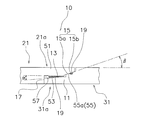
- the adhesive 19 is disposed on the screw bottom of the first screwing portion 13.
- the screw bottom portion of the first screwing portion 13 (and / or the screw thread portion of the first screwing portion).
- the thread part (and / or the screw bottom part of the 2nd screwing part 53) of the 2nd screwing part 53 is joined by an adhesive agent.
- the adhesive 19 may be disposed between the first engaging portion 15 and the second engaging portion 55 and between the first screwing portion 13 and the second screwing portion 53. Good.
- grooves 15 c and 15 d (an example of the second groove) for arranging the adhesive 19 may be arranged in the vicinity of the first screwing portion 13. Further, only one of the groove portions 15 c and 15 d may be disposed in the vicinity of the first screwing portion 13.
- the vicinity of the first threaded portion 13 shown here refers to, for example, the distal end portion of the first main body portion 11 and / or the first threaded portion 13 and the first engaging portion 15 (the first engaging portion 15 in the first main body portion 11) 1 between the inclined portions 15a).
- the adhesive 19 disposed in the groove portion 15c is applied to the second screwing portion 53, and this adhesion is performed.
- the first screwing portion 13 and the second screwing portion 53 can be joined by the agent 19.
- the adhesive 19 arranged in the groove 15 d can join the space between the outer peripheral portion 31 a of the impeller shell 31 and the outer peripheral portion 21 a of the front cover main body 21.
- the groove 15b extends in the circumferential direction of the first engagement portion 15 (first inclined portion 15a)
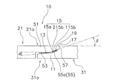
- the groove 15b is divided into a first groove 115b extending in the circumferential direction of the first engaging portion 15 (first inclined portion 15a) and a first engaging portion 15 (first inclined).
- You may comprise from the 2nd groove part 215b extended in the inclination direction (direction which goes to the 1st screwing part 13) of the part 15a).
- a predetermined number of second groove portions 215b are arranged at a predetermined interval in the circumferential direction.
- the number of the second groove portions 215b may be one.
- the adhesive 19 when the adhesive 19 is disposed in the first groove 115b and / or the second groove 215b, the adhesive 19 is not only placed between the first engagement part 15 and the second engagement part 55 but also in the first groove part 215b.
- the first screwing portion 13 and the second screwing portion 53 can be guided and arranged. Further, the excessive adhesive 19 can be guided and arranged toward the first screwing portion 13 and the second screwing portion 53.
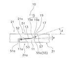
- the first connecting structure 10 of the first embodiment includes a small diameter portion 51a having a smaller diameter than the second screwing portion 53, and a seal member 52 capable of contacting the small diameter portion 51a. You may further have the annular groove part 11a for arrange
- the small diameter part 51 a is formed on the inner peripheral part of the second main body part 51.
- the small diameter part 51 a is smaller in diameter than the inner diameter of the thread of the second screwing part 53.
- the seal member 52 seals the hydraulic oil by contacting the small diameter portion 51a.
- the seal member 52 is, for example, an O-ring.
- the annular groove portion 11 a is formed in an annular shape on the outer peripheral portion of the first main body portion 11.
- a seal member 52 is disposed in the annular groove portion 11a.
- the first contact portion 17 and the second contact portion 57 are connected to the impeller shell.
- the inner and outer sides of 31 and the front cover body 21 may be in contact with each other. Thereby, it is possible to more reliably prevent entry of foreign matter into the internal space of the torque converter 1, for example, entry of the adhesive 19.
- the configuration of the torque converter according to the second embodiment of the present invention is substantially the same as that of the first embodiment except for the connection configuration of the front cover 2 and the impeller 3 and the configuration of the second connection structure 110.
- 2nd Embodiment detailed description is abbreviate
- the configuration omitted here conforms to the description of the first embodiment.
- the torque converter 1 mainly includes a front cover 2, an impeller 3, a turbine 4, a stator 5, a lock-up device 9, and a second connection structure 110 (an example of a connection structure). have.
- the same reference numerals are given to the same configurations as those in the first embodiment.
- the impeller 3 is connected to the front cover 2.
- the impeller 3 mainly includes an impeller shell 31 (an example of a first member), a plurality of impeller blades 32, and an impeller hub 33 (an example of a second member, an example of a first boss member).
- FIG. 3 shows an example in which the impeller shell 31 is connected to the front cover 2 by welding, but the impeller shell 31 is connected to the front via the first connection structure 10 (see FIG. 1) described above.
- the cover 2 may be connected.
- the impeller shell 31 has a first hole 131.
- the first hole 131 is a hole formed around the rotation axis O of the impeller 3.
- the impeller hub 33 is connected to the first hole 131.
- 4A is a partially enlarged view of the second connection structure 110 of FIG. In FIG. 4A, each part is schematically expressed by enlarging or the like in order to facilitate the description of the second connection structure 110.
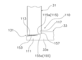
- the second connection structure 110 is for connecting the impeller shell 31 and the impeller hub 33. Specifically, the second connection structure 110 connects the center portion of the impeller shell 31 and the end portion of the impeller hub 33 with respect to the rotation axis O of the impeller 3. By connecting the impeller shell 31 and the impeller hub 33 by the second connecting structure 110, a hydraulic oil chamber (an example of a space) that can be filled with hydraulic oil is formed inside the impeller hub 33.
- the second connection structure 110 is provided at the end 33a of the impeller hub 33 (the end of the first boss member) and the first hole 131 of the impeller shell 31.
- the second connection structure 110 provided at the end portion 33a of the impeller hub 33 includes a third main body portion 111, a third screwing portion 113, a third engagement portion 115, and a third contact portion 117. ing.
- the third main body 111 is provided at the end 33 a of the impeller hub 33. Specifically, the third main body 111 is formed to protrude outward from the end 33 a of the impeller hub 33.
- the 3rd main-body part 111 is formed in the substantially cylindrical shape.
- the third main body 111 is disposed on the inner periphery of the first hole 131 of the impeller shell 31.
- the third engaging portion 115 has a third inclined portion 115a.
- the second connection structure 110 provided in the first hole 131 of the impeller shell 31 further includes a fourth screwing portion 153, a fourth engagement portion 155, and a fourth contact portion 157.
- the fourth screwing portion 153 is provided on the inner peripheral portion of the first hole portion 131.
- the fourth engaging portion 155 is provided on the inner peripheral portion of the first hole portion 131.
- the fourth engaging portion 155 has a fourth inclined portion 155a.
- the fourth contact portion 157 is a portion of the first hole 131 on the transmission side.
- the opening side of the first hole 131 of the impeller shell 31 is the side on which the end of the impeller hub 33 is mounted.
- the opening side of the end portion of the impeller hub 33 is a side on which the first hole 131 of the impeller shell 31 is mounted.
- the adhesive 19 is applied to the third engagement portion 115 (third inclined portion 115a).
- the tip end portion of the third screwing portion 113 of the impeller hub 33 is screwed into the fourth screwing portion 153 of the impeller shell 31.
- the third main body 111 is deformed radially inward due to the inclination of the screw bottom portion of the third screwing portion 113.
- the third engaging portion 115 (third inclined portion 115a) is changed to the fourth engaging portion 155 (fourth inclined portion). Part 155a).
- the 3rd screwing part 113 is further screwed in the 4th screwing part 153, the 3rd engaging part 115 (3rd inclination part 115a) will follow the 4th engaging part 155 (4th inclination part 155a).
- the third main body 111 is further deformed in the radial direction.
- the third contact portion 117 contacts the fourth contact portion 157 the impeller hub 33 and the impeller shell 31 are positioned in the axial direction.
- the adhesive 19 is hardened between the third engagement portion 115 and the fourth engagement portion 155, the connection between the impeller hub 33 and the impeller shell 31 is completed.
- the third screwing portion 113 and the fourth screwing portion 153 are screwed together, and the third engaging portion 115 and the fourth engaging portion 155 are engaged. That is, not only the third screwing portion 113 and the fourth screwing portion 153 are screwed but also the third engaging portion 115 and the fourth engaging portion 155 are further engaged, so that the impeller shell 31 and the impeller hub 33 can be reliably connected.
- the 1st hole 131 of the impeller shell 31 showed the example in case the 2nd connection structure 110 was comprised.
- the first boss portion 132 is provided on the impeller shell 31 around the rotation axis O of the impeller 3 so that the first boss portion 132 constitutes the second connection structure 110. Also good.
- the first boss part 132 protrudes outward from the first hole part 131 of the impeller shell 31 and is integrally formed.
- the second connection structure 110 is provided at the end 33a of the impeller hub 33 and the first boss 132 of the impeller shell 31.
- the second connection structure 110 is for connecting the end portion 33 a of the impeller hub 33 and the first boss portion 132 of the impeller shell 31.
- the second connection structure 110 includes the first boss portion 132 of the impeller shell 31 and the end portion 33a of the impeller hub 33 (an example of the end portion of the second boss member) with reference to the rotation axis O of the impeller 3. , Connect to each other.
- the first boss 132 and / or the impeller hub 33 can be filled with hydraulic oil.
- An oil chamber (an example of a space) is formed.
- the configuration of the second connection structure 110 is substantially the same as the configuration of the first embodiment shown in FIG. 2A, as shown in FIG. 4B.
- 4B is a line symmetry diagram with respect to a straight line perpendicular to the rotation axis O of FIG. 1 in FIG. 2A.
- the second connection structure 110 provided at the end portion 33 a of the impeller hub 33 has the configuration of the first connection structure 10 of the outer peripheral portion 31 a on the opening side of the impeller shell 31 (see FIG. 2A). Is substantially the same. Further, the second connection structure 110 provided in the first boss portion 132 of the impeller shell 31 is the first connection portion provided on the outer peripheral portion 21a on the opening side of the front cover main body 21 except for the formation position of the fourth main body portion 133. It is substantially the same as the structure of the connection structure 10 (see FIG. 2A).
- the fourth main body portion 133 is formed to protrude outward on the distal end side of the first boss portion 132.
- the fourth main body 133 is formed in a substantially cylindrical shape.
- the fourth main body portion 133 is disposed inside the end portion 33 a of the impeller hub 33. That is, the end portion 33 a of the impeller hub 33 is connected to the outer peripheral portion of the first boss portion 132 of the impeller shell 31 by the second connection structure 10.
- the second connection structure 110 can be configured, and the impeller shell 31 and the impeller hub 33 can be reliably connected.
- the end portion 33a of the impeller hub 33 is connected to the outer peripheral portion of the first boss portion 132 of the impeller shell 31 is shown, but the first boss portion 132 of the impeller shell 31 is connected to the impeller hub 33. You may make it connect with the outer peripheral part of the edge part 33a.
- grooves 15b, 15c, 15d, 115b, and 215b may be formed, and the adhesive 19 may be disposed in the grooves 15b, 15c, 15d, 115b, and 215b.
- the configuration of the torque converter according to the third embodiment of the present invention is substantially the same as that of the first embodiment except for the connection configuration of the front cover 2 and the impeller 3 and the configuration of the third connection structure 210.
- 3rd Embodiment detailed description is abbreviate
- the configuration omitted here conforms to the description of the first embodiment.
- the torque converter 1 mainly includes a front cover 2, an impeller 3, a turbine 4, a stator 5, a lockup device 9, and a third connection structure 210 (an example of a connection structure). have.
- the front cover 2 is connected to the impeller 3.
- the front cover 2 includes a front cover main body 21 (an example of a first member) and a front boss 23 (an example of a second member, an example of a second boss member).
- FIG. 3 shows an example in which the front cover 2 is connected to the impeller shell 31 by welding, but the impeller shell 31 is connected to the front via the first connecting structure 10 (see FIG. 1) described above.
- the cover 2 may be connected.
- the front cover main body 21 has a second hole 121.
- the second hole 121 is a hole formed around the rotation axis O of the impeller 3.
- the front boss 23 is connected to the second hole 121 of the front boss 23.
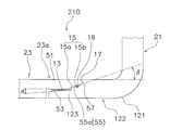
- FIG. 6 is a partially enlarged view of the third connection structure 210 of FIG. In FIG. 6, in order to facilitate the explanation of the third connection structure 210, each part is schematically expressed by enlargement or the like.
- the third connection structure 210 is for connecting the front cover body 21 and the front boss 23. Specifically, the third connection structure 210 connects the center portion of the front cover body 21 with respect to the rotation axis O of the impeller 3 and the end portion 23a of the front boss 23 (end portion of the second boss member) to each other. To do.
- a hydraulic oil chamber an example of a space
- hydraulic oil is formed inside the front boss 23.
- the third connection structure 210 is provided at the end 23a of the front boss 23 and the second hole 121 of the front cover body 21.
- the third connection structure 210 provided at the end 23a of the front boss 23 includes a fifth main body 211, a fifth screwing portion 213, a fifth engagement portion 215, and a fifth contact portion 217. is doing.
- the fifth main body 211 is provided at the end 23 a of the front boss 23. Specifically, the fifth main body 211 is formed to protrude outward from the end 23 a of the front boss 23.
- the fifth main body 211 is formed in a substantially cylindrical shape.
- the fifth main body 211 is disposed on the inner peripheral portion of the second hole 121 of the front cover main body 21.
- the fifth engaging portion 215 has a fifth inclined portion 215a.
- the third connection structure 210 provided in the second hole 121 of the front cover main body 21 further includes a sixth screwing portion 253, a sixth engaging portion 255, and a sixth contact portion 257.
- the sixth screwing part 253 is provided on the inner peripheral part of the second hole part 121.
- the sixth engaging portion 255 is provided on the inner peripheral portion of the second hole portion 121.
- the sixth engaging portion 255 has a sixth inclined portion 255a.
- the sixth contact portion 257 is a portion of the second hole 131 on the engine side.
- the opening side of the second hole 121 of the front cover body 21 is the side on which the end 23a of the front boss 23 is mounted.
- the opening side of the end 23a of the front boss 23 is the side on which the second hole 121 of the front cover body 21 is mounted.
- the adhesive 19 is applied to the fifth engagement portion 215 (the fifth inclined portion 215a).
- the tip end portion of the fifth screwing portion 213 of the front boss 23 is screwed into the sixth screwing portion 253 of the second hole 121 of the front cover body 21.
- the fifth main body portion 211 is deformed radially inward due to the inclination of the screw bottom portion of the fifth screwing portion 213.
- the fifth engaging portion 215 (the fifth inclined portion 215a) is changed to the sixth engaging portion 255 (the sixth inclined portion). Part 255a).
- the fifth engaging portion 215 (fifth inclined portion 215a) follows the sixth engaging portion 255 (sixth inclined portion 255a).
- the fifth main body 211 is further deformed in the radial direction.
- the front boss 23 and the front cover body 21 are positioned in the axial direction.
- the 5th screwing part 213 and the 6th screwing part 253 are screwed together, and the 5th engaging part 215 and the 6th engaging part 255 are engaged. That is, not only the fifth screwing part 213 and the sixth screwing part 253 are screwed but also the fifth engaging part 215 and the sixth engaging part 255 are further engaged, The front boss 23 can be reliably connected.
- the 2nd hole part 121 of the front cover main body 21 showed the example in case the 3rd connection structure 210 was comprised.
- the second boss portion 122 may be provided on the front cover body 21 around the rotation axis O of the impeller 3, and the second boss portion 122 may constitute the third connection structure 210.
- the second boss portion 122 protrudes outward from the second hole portion 121 of the front cover body 21 and is integrally formed.
- the third connection structure 210 is provided on the end 23a of the front boss 23 and the second boss 122 of the front cover body 21.
- the third connection structure 210 is for connecting the end 23 a of the front boss 23 and the second boss 122 of the front cover body 21.
- the third connection structure 210 includes the second boss portion 122 of the front cover body 21 and the end portion 23a of the front boss 23 (an example of the end portion of the second boss member) with respect to the rotation axis O of the impeller 3. ) Are connected to each other.
- the third connecting structure 210 By connecting the end portion 23a of the front boss 23 and the second boss portion 122 of the front cover body 21 by the third connecting structure 210, the second boss portion 122 and / or the front boss 23 is filled with hydraulic oil.
- a possible hydraulic oil chamber (an example of a space) is formed.
- the configuration of the third connection structure 210 is substantially the same as the configuration of the first embodiment shown in FIG. 2A, as shown in FIG. 6B.
- the third connection structure 210 provided at the end 23a of the front boss 23 is the configuration of the first connection structure 10 provided at the outer peripheral portion 21a on the opening side of the front cover body 21 (FIG. (See 2A).
- the third connection structure 210 provided in the second boss portion 122 of the front cover body 21 is the first connection structure 10 of the outer peripheral portion 31a on the opening side of the impeller shell 31 except for the position where the sixth body portion 123 is formed. (See FIG. 2A) is substantially the same.
- the sixth main body portion 133 is formed to protrude outward on the distal end side of the second boss portion 122.
- the sixth main body portion 123 is formed in a substantially cylindrical shape.
- the sixth main body 123 is disposed inside the end 23 a of the front boss 23. That is, the end portion 23 a of the front boss 23 is connected to the outer peripheral portion of the second boss portion 122 of the front cover body 21 by the third connection structure 210.
- the third connection structure 210 can be configured, and the front cover body 21 and the front boss 23 can be reliably connected.
- the end portion 23a of the front boss 23 is connected to the outer peripheral portion of the second boss portion 122 of the front cover main body 21
- the second boss portion 122 of the front cover main body 21 is Alternatively, the front boss 23 may be connected to the outer peripheral portion of the end portion 23a.
- connection structure 210 has been mainly described in the third embodiment, the third connection structure 210 and the second connection structure 110 of the second embodiment may be used in combination.
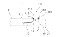
- the fourth connection structure 310 includes the first connection structure 10 described in the first embodiment and the fixing structure 410. Since the 1st connection structure 10 is the same structure as 1st Embodiment, description is abbreviate
- the fixing structure 410 is provided on the impeller 3 and the front cover 2, and fixes the connection between the impeller 3 and the front cover 2.
- the fixing structure 410 includes a holding member 411 and a welded portion 412.
- the holding member 411 is formed in a plate shape.
- the holding member 411 is disposed on the outer peripheral portion 31 a of the impeller shell 31 and the outer peripheral portion 21 a of the front cover main body 21.
- each of the plurality of holding members 411 is disposed at a predetermined interval in the circumferential direction in a state of straddling the outer peripheral portion 31 a of the impeller shell 31 and the outer peripheral portion 21 a of the front cover main body 21.
- the welded part 412 fixes the connection between the outer peripheral part 31 a of the impeller shell 31 and the outer peripheral part 21 of the front cover body 21 via the holding member 411.
- the welded portion 412 is provided on the holding member 411, the outer peripheral portion of the impeller shell 31, and the outer peripheral portion of the front cover 2.
- the welding part 412 fixes the outer peripheral part of the holding member 411 and the impeller shell 31, and the outer peripheral part of the holding member 411 and the front cover 2 by welding, for example, projection welding.
- the fixing structure 410 allows the impeller 3 and the front cover 2 to be reliably connected and fixed.
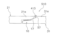
- a fixed structure 510 may be used.
- the outer peripheral portion 31a of the impeller shell 31 and the outer peripheral portion 21a of the front cover main body 21 are It is directly fixed by the welded portion 413.
- the outer peripheral part 31a of the impeller shell 31 and the outer peripheral part 21a of the front cover main body 21 are joined by spot welding, for example. Even if the fixing structure 510 is configured in this manner, the impeller 3 and the front cover 2 can be more reliably connected and fixed.
- a fixed structure 610 may be configured as shown in FIG. 8B.
- the fixing structure 610 includes a caulking portion 611 and a concave portion 612.
- the caulking portion 611 is provided on the outer peripheral portion 21 a of the front cover main body 21, for example, the second main body portion 51.
- the recess 612 is provided in the outer peripheral portion 31 a of the impeller shell 31, for example, the first main body portion 11.
- the second contact portion 57 is provided at the tip portion (tip surface) of the caulking portion 611.
- the caulking portion 611 is in contact with the concave portion 612 of the outer peripheral portion 31 a of the impeller shell 31.
- the caulking is fixed.
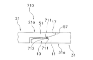
- the fixing structure 710 may be configured as shown in FIG. 8C.
- the fixing structure 710 includes a pair of groove portions 711 and a snap ring 712 (an example of a ring member).
- One of the pair of groove portions 711 is provided on the inner peripheral side of the outer peripheral portion 31a (second main body portion 51) of the impeller shell 31.
- the other of the pair of groove portions 711 is provided on the outer peripheral side of the outer peripheral portion 21 a (first main body portion 11) of the front cover main body 21.
- the snap ring 712 is disposed in the pair of grooves 711 and prevents the impeller 3 and the front cover 2 from coming off from each other in the axial direction.
- the impeller 3 is attached to the front cover 2 by the first coupling structure 10 as described in the first embodiment.
- the first contact portion 17 of the impeller shell 31 and the second contact portion 57 of the front cover main body 21 are in contact with each other, and the groove portion 711 of the impeller shell 31 is disposed at a position facing the groove portion 711 of the front cover main body 21.
- the snap ring 712 disposed in the groove portion 711 of the impeller shell 31 engages with the groove portion 712 of the front cover main body 21.
Landscapes
- Engineering & Computer Science (AREA)
- General Engineering & Computer Science (AREA)
- Mechanical Engineering (AREA)
- Structures Of Non-Positive Displacement Pumps (AREA)
Abstract
第1部材及び第2部材を確実に連結できるトルクコンバータを、提供する。本トルクコンバータ(1)では、連結構造(10)が、第1螺合部(13)と、第1係合部(15)と、第2螺合部(53)と、第2係合部(55)とを、有している。第1螺合部(13)は、インペラシェル(31)及びフロントカバー本体(21)のいずれか一方に設けられる。第1係合部(15)は、第1螺合部(13)に並べてインペラシェル(31)及びフロントカバー本体(21)のいずれか一方に設けられる。第2螺合部(53)は、第1螺合部(13)に螺合可能であり、インペラシェル(31)及びフロントカバー本体(21)のいずれか他方に設けられる。第2係合部(55)は、第1係合部(15)に係合可能であり、インペラシェル(31)及びフロントカバー本体(21)のいずれか他方に設けられる。
Description
本発明は、トルクコンバータに関する。
従来のトルクコンバータは、主に、フロントカバーと、3種の羽根車(インペラ、タービン、ステータ)とから構成されている(特許文献1を参照)。インペラは、インペラシェルと、インペラシェルの内側に装着された複数のインペラブレードと、インペラシェルの内周端に保持されているインペラハブとを有している。タービンは、タービンシェルと、タービンシェルに装着された複数のタービンブレードとを有している。このトルクコンバータでは、フロントカバー及びインペラシェルが、ネジ構造を介して互いに連結されている。
従来のトルクコンバータでは、エンジンからトルクが入力され、インペラがフロントカバーとともに回転すると、この回転により作動油がインペラ、タービン、ステータの間を循環する。この循環はステータによって整流されながら、作用油によってインペラ及びタービンが共に回転する。しかしながら、従来のネジ構造による連結では、エンジンからのトルクによって、フロントカバー及びインペラシェルが回転すると、両者の連結が緩んでしまうおそれがある。
本発明は、上記の問題に鑑みてなされたものであって、本発明の目的は、第1部材及び第2部材を確実に連結できるトルクコンバータを、提供することにある。
(1)本発明の一側面に係るトルクコンバータは、回転可能な第1部材と、第1部材とともに作動流体を充填可能な空間を形成する第2部材と、第1部材及び第2部材を連結する連結構造とを、備えている。連結構造は、第1螺合部と、第1係合部と、第2螺合部と、第2係合部とを、有している。第1螺合部は、第1部材及び第2部材のいずれか一方に設けられる。第1係合部は、第1螺合部に並べて第1部材及び第2部材のいずれか一方に設けられる。第2螺合部は、第1螺合部に螺合可能であり、第1部材及び第2部材のいずれか他方に設けられる。第2係合部は、第1係合部に係合可能であり、第1部材及び第2部材のいずれか他方に設けられる。
本トルクコンバータでは、連結構造が、第1部材及び第2部材を連結する。連結構造では、第1螺合部及び第2螺合部が螺合し、且つ第1係合部及び第2係合部が係合する。すなわち、第1螺合部及び第2螺合部が螺合するだけでなく、第1係合部及び第2係合部がさらに係合させているので、第1部材及び第2部材を確実に連結できる。
(2)本発明の別の側面に係るトルクコンバータは、次のように構成することが好ましい。連結構造は、第1当接部と、第2当接部とを、さらに有する。第1当接部は、第1部材及び第2部材のいずれか一方に設けられる。第2当接部は、第1部材及び第2部材のいずれか他方に設けられる。第2当接部及び第1当接部が当接することによって、第1部材及び第2部材が互いに位置決めされる。
本トルクコンバータでは、連結構造において、第2当接部及び第1当接部が当接することによって、第1部材及び第2部材が互いに位置決めされる。これにより、第1部材及び第2部材の連結及び位置決めを確実に行うことができる。
(3)本発明の別の側面に係るトルクコンバータは、次のように構成することが好ましい。第1螺合部及び第2螺合部の間と、第1係合部と第2係合部との間との少なくともいずれか一方には、接着剤が配置される。
本トルクコンバータでは、第1螺合部及び第2螺合部の間と、第1係合部と第2係合部との間との少なくともいずれか一方には、接着剤が配置されるので、第1部材及び第2部材をより確実に連結することができる。
(4)本発明の別の側面に係るトルクコンバータは、次のように構成することが好ましい。連結構造は、接着剤を配置するための第1溝部を、さらに有する。第1溝部は、第1係合部及び第2係合部の少なくともいずれか一方に、設けられる。
本トルクコンバータでは、接着剤が第1溝部に配置されるので、第1係合部及び第2係合部を安定的且つ確実に接着することができる。すなわち、第1部材及び第2部材を安定的且つ確実に連結することができる。
(5)本発明の別の側面に係るトルクコンバータは、次のように構成することが好ましい。連結構造は、接着剤を配置するための第2溝部を、さらに有する。第2溝部は、第1螺合部の近傍及び第2螺合部の近傍の少なくともいずれか一方に、設けられる。
本トルクコンバータでは、接着剤が第2溝部に配置されるので、第1螺合部及び第2螺合部の螺合を安定的且つ確実に保持することができる。すなわち、第1部材及び第2部材を安定的且つ確実に連結することができる。
(6)本発明の別の側面に係るトルクコンバータは、次のように構成することが好ましい。第1係合部は、前記第1部材の回転軸に沿う方向に傾斜する第1傾斜部を、有する。第2係合部は、第1傾斜部に当接可能な第2傾斜部を、有する。
本トルクコンバータでは、第1係合部の第1傾斜部及び第2係合部の第2傾斜部が互いに当接可能であるので、第1螺合部及び第2螺合部を螺合させながら、第1係合部及び第2係合部をスムーズに係合させることができる。
(7)本発明の別の側面に係るトルクコンバータは、次のように構成することが好ましい。第1係合部及び第2係合部は、前記第1部材の回転軸を基準とした回転方向に形成される。第1係合部及び第2係合部のいずれか一方は、第1係合部及び第2係合部のいずれか他方の内周側に配置される。第1係合部及び第2係合部のいずれか一方の外径は、第1係合部及び第2係合部のいずれか他方の内径より大きい。
本トルクコンバータでは、第1係合部(又は第2係合部)の外径が、第2係合部(又は第1係合部)の内径より大きいので、第1係合部及び第2係合部の係合状態を確実に保つことができる。
(8)本発明の別の側面に係るトルクコンバータは、次のように構成することが好ましい。前記第1部材の回転軸に沿う方向に並ぶ第1螺合部のネジ底部、及び前記第1部材の回転軸に沿う方向に並ぶ第2螺合部のネジ底部の少なくともいずれか一方は、第1部材の回転軸に沿う方向に傾斜している。
本トルクコンバータでは、前記第1部材の回転軸に沿う方向に並ぶ第1螺合部のネジ底部、及び前記第1部材の回転軸に沿う方向に並ぶ第2螺合部のネジ底部の少なくともいずれか一方を、上記のように傾斜させることによって、第1螺合部及び第2螺合部をスムーズに螺合させることができる。
(9)本発明の別の側面に係るトルクコンバータは、次のように構成することが好ましい。第1係合部は、第1部材の回転軸に沿う方向おいて傾斜する第1傾斜部を、有する。第2係合部は、第1傾斜部に当接可能な第2傾斜部を、有する。第1部材の回転軸に沿う方向に向かって傾斜する第1螺合部のネジ底部及び前記第2螺合部のネジ底部の少なくともいずれか一方の傾斜角度は、第1傾斜部及び第2傾斜部の少なくともいずれか一方の傾斜角度より、小さい。
本トルクコンバータでは、ネジ底部の傾斜角度が、傾斜部の傾斜角度より小さいので、第1螺合部及び第2螺合部をスムーズ且つ確実に螺合させることができる。
(10)本発明の別の側面に係るトルクコンバータは、次のように構成することが好ましい。第1部材及び第2部材は、エンジンとトランスミッションとの間に配置される。第1部材はトランスミッション側に配置され、第2部材はエンジン側に配置される。エンジン側から見た場合、第2螺合部が第1螺合部に対してねじ込まれる方向は、エンジンの回転方向と同じである
本トルクコンバータでは、上記の構成をエンジン側から見て、第2螺合部が第1螺合部に対してねじ込まれる方向と、エンジンの回転方向とを同じに設定しているので、エンジンによって、第1部材及び第2部材が回転しても、第1螺合部及び第2螺合部の螺合の緩みを確実に防止することができる。
本トルクコンバータでは、上記の構成をエンジン側から見て、第2螺合部が第1螺合部に対してねじ込まれる方向と、エンジンの回転方向とを同じに設定しているので、エンジンによって、第1部材及び第2部材が回転しても、第1螺合部及び第2螺合部の螺合の緩みを確実に防止することができる。
(11)本発明の別の側面に係るトルクコンバータは、次のように構成することが好ましい。連結構造は、第1部材及び第2部材の少なくともいずれか一方に設けられ第1部材及び第2部材の連結を固定するための固定構造を、さらに有している。
本トルクコンバータでは、連結構造が固定構造をさらに有しているので、第1部材及び第2部材の連結を、より確実に固定することができる。
(12)本発明の別の側面に係るトルクコンバータは、次のように構成することが好ましい。固定構造は、第1部材及び第2部材の連結を固定するための溶接部を、有する。
本トルクコンバータでは、第1部材及び第2部材の連結を、溶接部によってより確実に固定することができる。
(13)本発明の別の側面に係るトルクコンバータは、次のように構成することが好ましい。溶接部は、保持部材を介して、第1部材及び第2部材の連結を固定する。
本トルクコンバータでは、第1部材及び第2部材の連結を、保持部材を介して、溶接部によってより確実に固定することができる。
(14)本発明の別の側面に係るトルクコンバータは、次のように構成することが好ましい。固定構造は、第1部材及び第2部材の少なくともいずれか一方に設けられるカシメ部を、有する。このカシメ部を、第1部材及び第2部材の少なくともいずれか他方にカシメ固定することによって、第1部材及び第2部材の連結が固定される。
本トルクコンバータでは、第1部材及び第2部材の連結を、カシメ部によって容易且つ確実に固定することができる。
(15)本発明の別の側面に係るトルクコンバータは、次のように構成することが好ましい。固定構造は、第1部材及び第2部材に設けられ互いに対向可能な一対の溝部と、一対の溝部に配置され第1部材及び第2部材を互いに抜け止めするリング部材とを、有する。
本トルクコンバータでは、第1部材及び第2部材の連結を、一対の溝部に配置されたリング部材によって、容易且つ確実に固定することができる。
(16)本発明の別の側面に係るトルクコンバータは、次のように構成することが好ましい。第1部材は、フロントカバーである。第2部材は、インペラである。連結構造は、フロントカバーの開口部及びインペラの開口部を、互いに連結する。
本トルクコンバータでは、フロントカバー及びインペラを、連結構造によって、確実に連結することができる。
(17)本発明の別の側面に係るトルクコンバータは、次のように構成することが好ましい。第1部材は、インペラシェルである。第2部材は、インペラシェルに連結される第1ボス部材である。連結構造は、インペラシェルの第1孔部及び第1ボス部材の端部を、互いに連結する。
本トルクコンバータでは、インペラシェル及びインペラに連結される第1ボス部を、連結構造によって、確実に連結することができる。
(18)本発明の別の側面に係るトルクコンバータは、次のように構成することが好ましい。第1部材は、フロントカバー本体である。第2部材は、フロントカバー本体に連結される第2ボス部材である。連結構造は、フロントカバー本体の第2孔部及び第2ボス部材の端部を、互いに連結する。
本トルクコンバータでは、フロントカバー本体及びフロントカバー本体に連結される第2ボス部を、連結構造によって、確実に連結することができる。
本発明のトルクコンバータは、第1部材及び第2部材を確実に連結できる。
[第1実施形態]
<トルクコンバータの全体構成>
図1は、本発明の第1実施形態に係るトルクコンバータ1を示している。ここでは、O-Oがトルクコンバータ1の回転軸である。図1の左側にエンジン(図示せず)が配置され、図1の右側にトランスミッション(図示せず)が配置されている。なお、以下では、トルクコンバータ1の回転軸Oを、インペラ3の回転軸Oと表現する場合がある。
<トルクコンバータの全体構成>
図1は、本発明の第1実施形態に係るトルクコンバータ1を示している。ここでは、O-Oがトルクコンバータ1の回転軸である。図1の左側にエンジン(図示せず)が配置され、図1の右側にトランスミッション(図示せず)が配置されている。なお、以下では、トルクコンバータ1の回転軸Oを、インペラ3の回転軸Oと表現する場合がある。
トルクコンバータ1は、エンジン側のクランクシャフト50から、トランスミッションのメインドライブシャフト60へと、トルクを伝達するための機構である。トルクコンバータ1は、主に、フロントカバー2(第2部材の一例)と、インペラ3(第1部材の一例)と、タービン4と、ステータ5と、ロックアップ装置9と、第1連結構造10(連結構造の一例)とを、有している。
<トルクコンバータの基本構成>
フロントカバー2は、エンジン側のクランクシャフト40にフレキシブルプレート41を介して連結される。具体的には、フロントカバー2は、フロントカバー本体21と、フロントボス23とを、有する。フロントカバー本体21は、インペラ3とともに、作動油を充填可能な作動油室を、形成する。フロントカバー本体21は、ナット部25を介して、フレキシブルプレート41に連結される。
フロントカバー2は、エンジン側のクランクシャフト40にフレキシブルプレート41を介して連結される。具体的には、フロントカバー2は、フロントカバー本体21と、フロントボス23とを、有する。フロントカバー本体21は、インペラ3とともに、作動油を充填可能な作動油室を、形成する。フロントカバー本体21は、ナット部25を介して、フレキシブルプレート41に連結される。
ナット部25は、ナット本体25aと、ナット本体25aと一体に形成された連結部25bとを、有している。ナット本体25aには、ボルト24を介して、フレキシブルプレート41が装着される。連結部25bは、例えば、雄ネジ部である。連結部25b(雄ネジ部)は、フロントカバー本体21に設けられた雌ネジ部22に、螺合する。
このように、連結部25b(雄ネジ部)をフロントカバー本体21の雌ねじ部22に螺合させた状態で、フレキシブルプレート41がボルト24によってナット本体25aに螺合される。これにより、フレキシブルプレート41が、フロントカバー2に固定される。
なお、ここでは、ナット部25(連結部25b)をフロントカバー本体21(雌ねじ部22)に螺合することによって、ナット部25をフロントカバー本体21に装着される場合の例を示したが、上記螺合に加えて、ナット部25(ナット本体25a)をフロントカバー本体21に溶接してもよい。
フロントボス23は、フロントカバー本体21に設けられている。フロントボス23は、フロントカバー本体21からエンジン側に向けて突出し、エンジン側のクランクシャフト40に対して、位置決めを行う。ここでは、フロントボス23は、例えば溶接によって、フロントカバー本体21に固定されている。
インペラ3は、第1連結構造10(後述する)を介して、フロントカバー2に連結される。インペラ3は、主に、インペラシェル31と、複数のインペラブレード32と、インペラハブ33とを、有している。インペラシェル31は、第1連結構造10によって、フロントカバー2に連結される。複数のインペラブレード32は、インペラシェル31の内側に保持される。インペラハブ33は、インペラシェル31の内周側(インペラ3の回転軸O側)に、設けられる。ここでは、インペラハブ33は、例えば溶接によって、インペラシェル31に固定されている。
タービン4は、作動油室内でインペラシェル31と対向するように配置されている。タービン4は、主に、タービンシェル4aと、タービンシェル4aに保持される複数のタービンブレード4bとを、有している。タービンシェル4aの内周部は、タービンハブ8のフランジ部に複数のリベットにより、保持されている。また、タービンハブ8の内周部には、トランスミッション側から延びるメインドライブシャフト60と連結するためのスプライン孔が形成されている。
ステータ5は、インペラ3とタービン4との間に配置されている。ステータ5は、ワンウェイクラッチを介して、ステータシャフト70に、保持されている。
ロックアップ装置9は、フロントカバー2とタービン4とを機械的に連結するための機構である。ロックアップ装置9は、フロントカバー2とタービン4との間に配置される。
<トルクコンバータの基本動作>
エンジン側のクランクシャフト40からのトルクは、フレキシブルプレート41からフロントカバー2に入力される。このトルクは、フロントカバー2に連結されたインペラシェル31に伝達され、インペラ3が回転する。すると、作動油が、インペラ3側からタービン4側へと流れる。この際、作動油は、ステータ5によって整流されながら、タービン4を回転させる。これにより、タービン4のトルクが、タービンハブ8を介して、メインドライブシャフト60に出力される。
エンジン側のクランクシャフト40からのトルクは、フレキシブルプレート41からフロントカバー2に入力される。このトルクは、フロントカバー2に連結されたインペラシェル31に伝達され、インペラ3が回転する。すると、作動油が、インペラ3側からタービン4側へと流れる。この際、作動油は、ステータ5によって整流されながら、タービン4を回転させる。これにより、タービン4のトルクが、タービンハブ8を介して、メインドライブシャフト60に出力される。
<第1連結構造の構成>
図2Aは、図1の第1連結構造10を部分的に拡大した図である。図2Aは、第1連結構造10を説明しやすくするために、各部を拡大等によって模式的に表現されている。
図2Aは、図1の第1連結構造10を部分的に拡大した図である。図2Aは、第1連結構造10を説明しやすくするために、各部を拡大等によって模式的に表現されている。
図1及び図2Aに示すように、第1連結構造10は、インペラ3とフロントカバー2とを連結するためのものである。詳細には、第1連結構造10は、インペラシェル31の外周部31a及びフロントカバー本体21の外周部21aを、互いに連結する。より詳細には、第1連結構造10は、インペラシェル31の開口側の外周部31a及びフロントカバー本体21の開口側の外周部21aを、互いに連結する。第1連結構造10によってインペラ3とフロントカバー2とを連結することによって、作動油を充填可能な作動油室(空間の一例)が、形成される。
図1に示すように、第1連結構造10は、インペラシェル31の開口側の外周部31aと、フロントカバー本体21の開口側の外周部21aとに、設けられる。
図2Aに示すように、インペラシェル31の開口側の外周部31aに設けられる第1連結構造10は、第1本体部11と、第1螺合部13と、第1係合部15と、第1当接部17とを、有している。第1螺合部13と、第1係合部15と、第1当接部17とは、インペラ3の回転軸Oに沿うように、並べて配置される。
第1本体部11は、インペラシェル31の外周部から外方に突出して形成されている。第1本体部11は、実質的に円筒状に形成されている。第1本体部11は、フロントカバー2の開口側における外周部の内側に配置される。すなわち、第1本体部11は、第2本体部51(後述する)の内周側に配置される。
第1螺合部13は、第1本体部11の外周部に一体に形成されている。詳細には、第1螺合部13は、開口側において、第1本体部11の外周部に一体に形成されている。
第1螺合部13は、フロントカバー2の第2螺合部53(後述する)に螺合可能である。ここでは、トランスミッション側から見て、第1螺合部13が第2螺合部53に対してねじ込まれる方向が、エンジンの回転方向とは反対になるように、第1螺合部13及び第2螺合部53は形成されている。
第1螺合部13は、例えば、雄ネジ部である。第1螺合部13の外径(ねじ山の径)は、インペラシェル31の外周部の外径より小さい。ネジ底部が、インペラ3の回転軸Oに沿う方向に傾斜するように、第1螺合部13は形成されている。
詳細には、インペラ3の回転軸Oに沿う方向に並ぶ第1螺合部13のネジ底部は、インペラ3の回転軸Oに沿う方向、すなわち第1本体部11が突出する方向において、回転軸Oに近づくように傾斜している。言い換えると、ネジ溝の谷径が、第1本体部11が突出する方向(第1本体部11の先端部)に向かって、徐々に小さくなっている。第1螺合部13のネジ底部の傾斜角度αは、第1係合部15の第1傾斜部15a(後述する)の傾斜角度βより、小さい。ここでは、第1螺合部13のネジ底部の傾斜角度は、例えば3度に設定されている。
なお、第1螺合部13の先端側のネジ山(又は第2螺合部53の先端側のネジ山)は、第2螺合部53の先端側のネジ溝(又は第1螺合部13の先端側のネジ溝)に、螺合可能である。
第1係合部15は、フロントカバー2の第2係合部55(後述する)に係合可能である。詳細には、第1係合部15は、第1螺合部13及び第2螺合部53の少なくとも一部が螺合した状態で、第2係合部55に係合可能である。
第1係合部15は、第1本体部11の外周部に一体に形成されている。詳細には、第1係合部15は、インペラ3の回転軸Oに沿う方向、すなわち第1本体部11が突出する方向において、第1本体部11の基端部と第1螺合部13との間に設けられている。第1係合部15は、インペラ3の回転軸Oを基準とした周方向(回転方向)において、第1本体部11の外周部に一体に形成されている。
第1係合部15と第2係合部55との間には、接着剤19が配置される。この接着剤19によって、第1係合部15と第2係合部55とは接合される。
より詳細には、第1係合部15は、第1傾斜部15aと、溝部15b(第1溝部の一例)とを、有している。第1傾斜部15aは、フロントカバー2の第2傾斜部55a(後述する)に当接可能である。第1係合部15が、第2係合部55に係合していない状態において、第1傾斜部15aの外径は、第2傾斜部55aの内径より大きい。この径の比較は、インペラ3の回転軸Oが延びる方向(軸方向)における同じ位置での比較である。また、第1傾斜部15aの外径は、第1螺合部13の外径(ネジ山径)より、大きい。
第1傾斜部15aは、インペラ3の回転軸Oに沿う方向に傾斜している。詳細には、第1傾斜部15aは、インペラ3の回転軸Oに沿う方向、すなわち第1本体部11が突出する方向において、回転軸Oに近づくように傾斜している。言い換えると、第1傾斜部15aが、第1本体部11が突出する方向に向かうにつれて、その外径が徐々に小さくなっている。第1傾斜部15aの傾斜角度βは、第1螺合部13の傾斜角度αより大きい。ここでは、第1傾斜部15aの傾斜角度βは、例えば5度に設定されている。
溝部15bは、第1傾斜部15aに形成されている。溝部15bは、第1傾斜部15aの周方向に延びる溝部である。溝部15bには、接着剤19を配置可能である。溝部15bに接着剤19を配置した状態で、第1傾斜部15a及び第2傾斜部55aを互いに係合させることによって、第1傾斜部15a及び第2傾斜部55aが接合される。
第1当接部17は、フロントカバー2の第2当接部57(後述する)に、当接可能である。第1当接部17は、例えば、第1本体部11の基端部に設けられる段差部である。段差部17は、第1本体部11の基端部外周に環状に形成されている。第1当接部17(段差部)には、第2当接部57が当接可能である。
フロントカバー本体21の開口側の外周部21aに設けられる第1連結構造10は、第2本体部51と、第2螺合部53と、第2係合部55と、第2当接部57とを、さらに有している。第2螺合部53と、第2係合部55と、第2当接部57とは、インペラ3の回転軸Oに沿うように、並べて配置される。
第2本体部51は、フロントカバー本体21の外周部21aから開口側に突出して形成されている。第2本体部51は、実質的に円筒状に形成されている。第2本体部51の外径は、フロントカバー本体21の外周部21aの外径と、実質的に同じである。第2本体部51は、インペラシェル31の外周部31aの外側に配置される。すなわち、第2本体部51は、第1本体部11の外周側に配置される。
第2螺合部53は、第2本体部51の内周部に一体に形成されている。詳細には、第2螺合部53は、インペラ3の回転軸Oに沿う方向、すなわち第2本体部51が突出する方向において、第2本体部51の基端部と第2係合部55との間に設けられている。
第2螺合部53は、インペラシェル31の第1螺合部13に螺合可能である。ここでは、エンジン側から見て、第2螺合部53が第1螺合部13に対してねじ込まれる方向が、エンジの回転方向と同じになるように、第1螺合部13及び第2螺合部53は形成されている。第2螺合部53は、例えば、雌ネジ部である。
第2係合部55は、インペラシェル31の第1係合部15に係合可能である。詳細には、第2係合部55は、第1螺合部13及び第2螺合部53の少なくとも一部が螺合した状態で、第1係合部15に係合可能である。
第2係合部55は、第2本体部51の内周部に一体に形成されている。第2係合部55は、開口側において、第2本体部51の内周部に一体に形成されている。第2係合部55は、インペラ3の回転軸Oを基準とした周方向(回転方向)において、第2本体部51の内周部に一体に形成されている。
詳細には、第2係合部55は、第2傾斜部55aを有している。第2傾斜部55aは、インペラシェル31の第1傾斜部15aに当接可能である。第2係合部55が、第1係合部15に係合していない状態において、第2傾斜部55aの内径は、第1傾斜部15aの外径より小さい。この径の比較は、軸方向における同じ位置での比較である。また、第2傾斜部55aの内径は、第2本体部51の外周部の外径より、小さい。
第2傾斜部55aは、インペラ3の回転軸Oに沿う方向に傾斜している。詳細には、第2傾斜部55aは、インペラ3の回転軸Oに沿う方向、すなわち第2本体部51が突出する方向において、インペラ3の回転軸Oから離れるように傾斜している。言い換えると、第2傾斜部55aが、第2本体部51が突出する方向に向かうにつれて、その内径が徐々に大きくなっている。第2傾斜部55aの傾斜角度βは、第1傾斜部15aの傾斜角度βと実質的に同じである。第2傾斜部55aの傾斜角度βは、第1螺合部13の傾斜角度αより大きい。ここでは、第2傾斜部55aの傾斜角度βは、例えば5度に設定されている。
第2傾斜部55aは、第1螺合部13及び第2螺合部53の少なくとも一部が螺合した状態で、第1傾斜部15aに係合可能である。具体的には、第1螺合部13の一部及び第2螺合部53の一部が螺合した状態で、第2傾斜部55aは第1傾斜部15aに当接する。そして、第1螺合部13及び第2螺合部53が互いにねじ込まれるにつれて、第2傾斜部55aは、第1傾斜部15aに当接した状態で、第1傾斜部15aに沿って移動する。
第2当接部57は、第1当接部17に当接可能である。第2当接部57は、第2本体部51の先端部に設けられている。詳細には、第2当接部57は、第2本体部51の先端面である。第2当接部57(第2本体部51の先端面)が、第1当接部17(第1当接部17の段差部)に当接することによって、インペラ3及びフロントカバー2が、軸方向に位置決めされる。
<第1連結構造の連結形態>
ここでは、第1連結構造10を介してインペラ3をフロントカバー2に対して装着する場合を、一例として説明する。なお、フロントカバー2をインペラ3に対して装着しても、ここに示す説明と同様に解釈することができる。
ここでは、第1連結構造10を介してインペラ3をフロントカバー2に対して装着する場合を、一例として説明する。なお、フロントカバー2をインペラ3に対して装着しても、ここに示す説明と同様に解釈することができる。
まず、溝部15bに接着剤19が配置される。次に、インペラ3(インペラシェル31)をフロントカバー2(フロントカバー本体21)に対向させた状態で、インペラシェル31の第1螺合部13の先端部が、フロントカバー2の第2螺合部53にねじ込まれる。そして、第1螺合部13が第2螺合部53にねじ込まれるにつれて、第1螺合部13のネジ底部の傾斜によって、第1本体部11及び第2本体部51の少なくともいずれか一方が径方向に変形する。
続いて、第1螺合部13が第2螺合部53に部分的にねじ込まれた状態で、第1係合部15(第1傾斜部15a)が第2係合部55(第2傾斜部55a)に当接する。そして、第1螺合部13が第2螺合部53にさらにねじ込まれると、第1係合部15(第1傾斜部15a)が第2係合部55(第2傾斜部55a)に沿って摺動し、第1本体部11及び第2本体部51の少なくともいずれか一方が径方向にさらに変形する。最後に、第1当接部17が第2当接部57に当接することによって、インペラ3及びフロントカバー2が、軸方向に位置決めされる。そして、溝部15bに配置された接着剤19が固まると、インペラ3及びフロントカバー2の連結が終了する。
ここで、上記の変形は、インペラシェル31の外周部31a(第1本体部11、第1螺合部13、第1係合部15)の剛性と、フロントカバー本体21の外周部21a(第2本体部51、第2螺合部53、第2係合部55)の剛性との剛性差によって、決定される。例えば、剛性が小さい方の外周部が、径方向に変形する。
より具体的には、まず、第1螺合部13が第2螺合部53に螺合しただけの状態では、第1螺合部13が形成された第1本体部11の剛性(又は第2螺合部53が形成された第2本体部51の剛性)が、第2螺合部53が形成された第2本体部51の剛性(又は第1螺合部13が形成された第1本体部11の剛性)より、小さければ、第1本体部11(又は第2本体部51)が、変形する。
一方で、第1係合部15(第1傾斜部15a)が第2係合部55(第2傾斜部55a)に係合した状態では、第1係合部15が形成された第1本体部11の剛性(又は第2係合部55が形成された第2本体部51の剛性)が、第2係合部55が形成された第2本体部51の剛性(又は第1係合部15が形成された第1本体部11の剛性)より、小さければ、第1本体部11(又は第2本体部51)が、変形する。
以上のように、第1連結構造10では、第1螺合部13及び第2螺合部53が螺合し、且つ第1係合部15及び第2係合部55が係合する。すなわち、第1螺合部13及び第2螺合部53が螺合するだけでなく、第1係合部15及び第2係合部55をさらに係合させているので、インペラ3及びフロントカバー2を確実に連結できる。
[他の実施形態]
(A1)前記第1実施形態では、インペラシェル31の外周部31aが、フロントカバー本体21の外周部21aの内周側に配置される場合の例を示した。これに代えて、フロントカバー本体21の外周部21aが、インペラシェル31の外周部31aの内周側に配置されるように、構成してもよい。
(A1)前記第1実施形態では、インペラシェル31の外周部31aが、フロントカバー本体21の外周部21aの内周側に配置される場合の例を示した。これに代えて、フロントカバー本体21の外周部21aが、インペラシェル31の外周部31aの内周側に配置されるように、構成してもよい。
この場合、第1実施形態で説明した、第1本体部11、第1螺合部13、第1係合部15、及び第1当接部17は、フロントカバー2に形成される。また、第1実施形態で説明した、第2本体部51、第2螺合部53、第2係合部55、及び第2当接部57は、インペラシェル31に形成される。
(B1)前記第1実施形態では、第1螺合部13のネジ底部だけが軸方向に傾斜する場合の例を示した。これに加えて、第2螺合部53のネジ底部も軸方向に傾斜するように構成してもよい。
(C1)前記第1実施形態では、接着剤19を配置するための溝部15bが、第1係合部15に形成される場合の例を示した。これに代えて、この溝部15bを、第2係合部55に形成してもよい。また、この溝部15bを、第1係合部15及び第2係合部55の両方に形成してもよい。
(D1)前記第1実施形態では、接着剤19を配置するための溝部15bが、第1係合部15に形成される場合の例を示した。これに代えて、この溝部15bを、第1当接部17及び第2当接部57の少なくともいずれか一方に形成してもよい。また、第1係合部15及び第2係合部55の少なくともいずれか一方と、第1当接部17及び第2当接部57の少なくともいずれか一方とに、形成してもよい。
(E1)前記第1実施形態では、接着剤19が、第1係合部15と第2係合部55との間に配置される場合の例を示したが、接着剤19は、第1螺合部13及び第2螺合部53の間に配置されてもよい(図2Eを参照)。
この場合、接着剤19は、第1螺合部13のネジ底部に配置される。この状態で、インペラシェル31の外周部31aが、フロントカバー本体21の外周部21aに装着されると、第1螺合部13のネジ底部(及び/又は第1螺合部のネジ山部)、及び第2螺合部53のネジ山部(及び/又は第2螺合部53のネジ底部)が、接着剤によって接合される。
なお、接着剤19は、第1係合部15及び第2係合部55の間と、第1螺合部13及び第2螺合部53の間とのいずれか一方に、配置されてもよい。
(F1)前記第1実施形態では、接着剤19を配置するための溝部15bが、第1係合部15に形成される場合の例を示した。これに代えて、図2Bに示すように、接着剤19を配置するための溝部15c,15d(第2溝部の一例)を、第1螺合部13の近傍に配置してもよい。また、溝部15c,15dのいずれか一方だけを、第1螺合部13の近傍に配置してもよい。ここに示した第1螺合部13の近傍とは、例えば、第1本体部11の先端部、及び/又は第1本体部11における第1螺合部13及び第1係合部15(第1傾斜部15a)の間である。
これにより、インペラシェル31の外周部31aが、フロントカバー本体21の外周部21aに装着される際に、溝部15cに配置された接着剤19が、第2螺合部53に塗布され、この接着剤19によって第1螺合部13及び第2螺合部53を接合することができる。一方で、溝部15dに配置された接着剤19は、インペラシェル31の外周部31aと、フロントカバー本体21の外周部21aとの間の空間を、接合することができる。
(G1)前記第1実施形態では、溝部15bが、第1係合部15(第1傾斜部15a)の周方向に延びる場合の例を示した。これに代えて、図2Cに示すように、溝部15bを、第1係合部15(第1傾斜部15a)の周方向に延びる第1溝部115bと、第1係合部15(第1傾斜部15a)の傾斜方向(第1螺合部13に向かう方向)に延びる第2溝部215bとから、構成してもよい。ここでは、所定数の第2溝部215bが、周方向に所定の間隔を隔てて配置されている。なお、第2溝部215bの数は、1つでもよい。
このように、接着剤19が第1溝部115b及び/又は第2溝部215bに配置されると、接着剤19を、第1係合部15及び第2係合部55の間だけでなく、第1螺合部13及び第2螺合部53に向けて誘導し配置することができる。また、余剰の接着剤19を、第1螺合部13及び第2螺合部53に向けて誘導し配置することができる。
(H1)前記第1実施形態の第1連結構造10が、図2Dに示すように、第2螺合部53より小径の小径部51aと、小径部51aに当接可能なシール部材52と、シール部材を配置するための環状溝部11aとを、さらに有していてもよい。
小径部51aは、第2本体部51の内周部に形成されている。小径部51aは、第2螺合部53のネジ山の内径より小径である。シール部材52は、小径部51aに当接することによって、作動油をシールする。シール部材52は、例えばOリングである。環状溝部11aは、第1本体部11の外周部に環状に形成されている。環状溝部11aには、シール部材52が配置される。
この場合、前記第1実施形態と同様に、インペラ3及びフロントカバー2が第1連結構造10によって連結されると、環状溝部11aに配置されたシール部材52が、小径部51aに当接する。これにより、シール性を向上することができる。
(I1)前記第1実施形態では、第1傾斜部15aの外径は、第2傾斜部55aの内径より大きい場合の例を示したが、第2傾斜部55aの内径が第1傾斜部15aの外径より小さくなるように構成してもよい。
(J1)前記第1実施形態では、第1当接部17及び第2当接部57が、インペラシェル31の外周側及びフロントカバー本体21の外周側において、互いに当接する場合の例を示した。これに代えて、図2Eに示すように、第1当接部17を第1本体部11の先端部に形成し、第2当接部57を、第2本体部51の基端部に設けられる段差部に形成してもよい。この場合、第1当接部17及び第2当接部57は、インペラシェル31の内周側及びフロントカバー本体21の内周側において、互いに当接する。これにより、トルクコンバータ1の内部空間への異物の侵入、例えば接着剤19の侵入を、防止することができる。
また、ここに示した構成(図2Eの構成)及び前記第1実施形態の構成(図2Aの構成)の両方を用いて、第1当接部17及び第2当接部57を、インペラシェル31の内外側及びフロントカバー本体21の内外側において、互いに当接させてもよい。これにより、トルクコンバータ1の内部空間への異物の侵入、例えば接着剤19の侵入を、より確実に防止することができる。
[第2実施形態]
本発明の第2実施形態に係るトルクコンバータの構成は、フロントカバー2及びインペラ3の連結形態と、第2連結構造110の構成とを除いて、第1実施形態と実質的に同様である。このため、第2実施形態では、第1実施形態と同様の構成については、詳細な説明を省略する。また、ここで省略された構成については、第1実施形態の説明に準ずる。
本発明の第2実施形態に係るトルクコンバータの構成は、フロントカバー2及びインペラ3の連結形態と、第2連結構造110の構成とを除いて、第1実施形態と実質的に同様である。このため、第2実施形態では、第1実施形態と同様の構成については、詳細な説明を省略する。また、ここで省略された構成については、第1実施形態の説明に準ずる。
図3に示すように、トルクコンバータ1は、主に、フロントカバー2と、インペラ3と、タービン4と、ステータ5と、ロックアップ装置9と、第2連結構造110(連結構造の一例)とを、有している。なお、図3では、第1実施形態と同様の構成については、同じ符号を付している。
インペラ3は、フロントカバー2に連結される。インペラ3は、主に、インペラシェル31(第1部材の一例)と、複数のインペラブレード32と、インペラハブ33(第2部材の一例、第1ボス部材の一例)とを、有している。図3では、インペラシェル31が、フロントカバー2に溶接によって連結される場合の例を示しているが、インペラシェル31は、上述した第1連結構造10(図1を参照)を介して、フロントカバー2に連結されてもよい。
図4Aに示すように、インペラシェル31は、第1孔部131を、有している。第1孔部131は、インペラ3の回転軸Oまわりに形成された孔部である。第1孔部131には、インペラハブ33が連結される。なお、図4Aは、図3の第2連結構造110を部分的に拡大した図である。図4Aは、第2連結構造110を説明しやすくするために、各部を拡大等によって模式的に表現されている。
第2連結構造110は、インペラシェル31とインペラハブ33とを連結するためのものである。詳細には、第2連結構造110は、インペラ3の回転軸Oを基準としたインペラシェル31の中央部、及びインペラハブ33の端部を、互いに連結する。第2連結構造110によってインペラシェル31とインペラハブ33とを連結することによって、インペラハブ33の内部には作動油を充填可能な作動油室(空間の一例)が、形成される。
第2連結構造110は、インペラハブ33の端部33a(第1ボス部材の端部)と、インペラシェル31の第1孔部131とに、設けられる。
インペラハブ33の端部33aに設けられる第2連結構造110は、第3本体部111と、第3螺合部113と、第3係合部115と、第3当接部117とを、有している。
第3本体部111は、インペラハブ33の端部33aに設けられる。詳細には、第3本体部111は、インペラハブ33の端部33aから外方に突出して形成されている。第3本体部111は、実質的に円筒状に形成されている。第3本体部111は、インペラシェル31の第1孔部131の内周部に配置される。第3係合部115は、第3傾斜部115aを有している。
その他の構成は、第1実施形態で説明した、第1螺合部13、第1係合部15、及び第1当接部17の構成と、実質的に同じである。このため、ここでは、これらの構成の説明は省略する。
インペラシェル31の第1孔部131に設けられる第2連結構造110は、第4螺合部153と、第4係合部155と、第4当接部157とを、さらに有している。第4螺合部153は、第1孔部131の内周部に設けられる。第4係合部155は、第1孔部131の内周部に設けられる。第4係合部155は、第4傾斜部155aを有している。第4当接部157は、第1孔部131のトランスミッション側の部分である。
その他の構成は、第1実施形態で説明した、第2螺合部53、第2係合部55、及び第2当接部57の構成と、実質的に同じである。このため、ここでは、これらの構成の説明は省略する。
なお、第2実施形態では、インペラシェル31の第1孔部131の開口側は、インペラハブ33の端部が装着される側である。インペラハブ33の端部の開口側は、インペラシェル31の第1孔部131が装着される側である。
このように第2連結構造110が構成された場合、まず、接着剤19が第3係合部115(第3傾斜部115a)に塗布される。次に、インペラハブ33の第3螺合部113の先端部が、インペラシェル31の第4螺合部153にねじ込まれる。そして、第3螺合部113が第4螺合部153にねじ込まれるにつれて、第3螺合部113のネジ底部の傾斜によって、第3本体部111が径方向内側に変形する。
次に、第3螺合部113が第4螺合部153に部分的にねじ込まれた状態で、第3係合部115(第3傾斜部115a)が第4係合部155(第4傾斜部155a)に当接する。そして、第3螺合部113が第4螺合部153にさらにねじ込まれると、第3係合部115(第3傾斜部115a)が第4係合部155(第4傾斜部155a)に沿って摺動し、第3本体部111が径方向にさらに変形する。最後に、第3当接部117が第4当接部157に当接することによって、インペラハブ33及びインペラシェル31が、軸方向に位置決めされる。そして、接着剤19が、第3係合部115及び第4係合部155との間で固まると、インペラハブ33及びインペラシェル31の連結が、完了する。
以上のように、第2連結構造110では、第3螺合部113及び第4螺合部153が螺合し、且つ第3係合部115及び第4係合部155が係合する。すなわち、第3螺合部113及び第4螺合部153が螺合するだけでなく、第3係合部115及び第4係合部155をさらに係合させているので、インペラシェル31及びインペラハブ33を確実に連結できる。
[他の実施形態]
(A2)前記第2実施形態では、インペラシェル31の第1孔部131が、第2連結構造110を構成する場合の例を示した。これに代えて、図4Bに示すように、第1ボス部132を、インペラ3の回転軸Oまわりにインペラシェル31に設け、第1ボス部132が第2連結構造110を構成するようにしてもよい。第1ボス部132は、インペラシェル31の第1孔部131から外方に突出して一体に形成される。
(A2)前記第2実施形態では、インペラシェル31の第1孔部131が、第2連結構造110を構成する場合の例を示した。これに代えて、図4Bに示すように、第1ボス部132を、インペラ3の回転軸Oまわりにインペラシェル31に設け、第1ボス部132が第2連結構造110を構成するようにしてもよい。第1ボス部132は、インペラシェル31の第1孔部131から外方に突出して一体に形成される。
この場合、第2連結構造110は、インペラハブ33の端部33aと、インペラシェル31の第1ボス部132とに、設けられる。第2連結構造110は、インペラハブ33の端部33aとインペラシェル31の第1ボス部132とを連結するためのものである。詳細には、第2連結構造110は、インペラ3の回転軸Oを基準としたインペラシェル31の第1ボス部132、及びインペラハブ33の端部33a(第2ボス部材の端部の一例)を、互いに連結する。第3連結構造210によってインペラハブ33の端部33aとインペラシェル31の第1ボス部132とを連結することによって、第1ボス部132及び/又はインペラハブ33の内部には作動油を充填可能な作動油室(空間の一例)が、形成される。
この第2連結構造110の構成は、図4Bに示すように、図2Aに示した第1実施形態の構成と、実質的に同じである。なお、図4Bは、図2Aにおける図1の回転軸Oに垂直な直線に対して線対称の図となっている。
例えば、図4Bに示すように、インペラハブ33の端部33aに設けられる第2連結構造110は、インペラシェル31の開口側の外周部31aの第1連結構造10の構成(図2Aを参照)と、実質的に同じである。また、インペラシェル31の第1ボス部132に設けられる第2連結構造110は、第4本体部133の形成位置を除いて、フロントカバー本体21の開口側の外周部21aに設けられた第1連結構造10の構成(図2Aを参照)と実質的に同じである。
このため、ここでは、図4Bを参照して、第4本体部133の説明のみ行う。なお、図2Aと同じ符号を付した構成、及び図4Aと同じ符号を付した構成について、ここで省略された説明は、図2A及び図4Aの説明に準ずる。
第4本体部133は、第1ボス部132の先端側において外方に突出して形成されている。第4本体部133は、実質的に円筒状に形成されている。第4本体部133は、インペラハブ33の端部33aの内側に、配置される。すなわち、第2連結構造10によって、インペラハブ33の端部33aが、インペラシェル31の第1ボス部132の外周部に連結される。
このように構成しても、第2連結構造110を構成することができ、インペラシェル31及びインペラハブ33を確実に連結できる。なお、ここでは、インペラハブ33の端部33aが、インペラシェル31の第1ボス部132の外周部に連結される場合の例を示したが、インペラシェル31の第1ボス部132が、インペラハブ33の端部33aの外周部に連結されるようにしてもよい。
(B2)上記の(A2)では、当接部17及び当接部57が、インペラシェル31の第1ボス部132の外周側及びインペラハブ33の外周側において、互いに当接する場合の例を示しているが、前記第1実施形態の(J1)の図2Eに示したように、当接部17及び当接部57を構成してもよい。
(C2)前記第2実施形態及び上記の(A2)では、接着剤19が第3係合部115(第3傾斜部115a)塗布される場合の例を示したが、第1実施形態及び/又は他の第1実施形態の実施形態と同様に、溝部15b,15c,15d,115b,215bを形成し、この溝部15b,15c,15d,115b,215bに接着剤19を配置してもよい。
(D2)前記第2実施形態及び上記の(A2)では、接着剤19が、第3係合部115と第4係合部155との間に配置される場合の例を示したが、接着剤19は、第3螺合部113及び第4螺合部153の間に配置されてもよい。
(E2)前記第2実施形態及び上記の(A2)では、第2連結構造110の説明を主に行ったが、第2連結構造110と第1実施形態の第1連結構造10とを、併用してもよい。
(F2)前記第2実施形態及び上記の(A2)の構成に、前記第1実施形態の(H1)の構成をさらに追加してもよい。
[第3実施形態]
本発明の第3実施形態に係るトルクコンバータの構成は、フロントカバー2及びインペラ3の連結形態と、第3連結構造210の構成とを除いて、第1実施形態と実質的に同様である。このため、第3実施形態では、第1実施形態と同様の構成については、詳細な説明を省略する。また、ここで省略された構成については、第1実施形態の説明に準ずる。
本発明の第3実施形態に係るトルクコンバータの構成は、フロントカバー2及びインペラ3の連結形態と、第3連結構造210の構成とを除いて、第1実施形態と実質的に同様である。このため、第3実施形態では、第1実施形態と同様の構成については、詳細な説明を省略する。また、ここで省略された構成については、第1実施形態の説明に準ずる。
図5に示すように、トルクコンバータ1は、主に、フロントカバー2と、インペラ3と、タービン4と、ステータ5と、ロックアップ装置9と、第3連結構造210(連結構造の一例)とを、有している。
フロントカバー2は、インペラ3に連結される。フロントカバー2は、フロントカバー本体21(第1部材の一例)と、フロントボス23(第2部材の一例、第2ボス部材の一例)とを、有している。図3では、フロントカバー2が、インペラシェル31に溶接によって連結される場合の例を示しているが、インペラシェル31は、上述した第1連結構造10(図1を参照)を介して、フロントカバー2に連結されてもよい。
図6に示すように、フロントカバー本体21は、第2孔部121を、有している。第2孔部121は、インペラ3の回転軸Oまわりに形成された孔部である。フロントボス23は、第2孔部121には、フロントボス23が連結される。なお、図6は、図5の第3連結構造210を部分的に拡大した図である。図6は、第3連結構造210を説明しやすくするために、各部を拡大等によって模式的に表現されている。
第3連結構造210は、フロントカバー本体21とフロントボス23とを連結するためのものである。詳細には、第3連結構造210は、インペラ3の回転軸Oを基準としたフロントカバー本体21の中央部、及びフロントボス23の端部23a(第2ボス部材の端部)を、互いに連結する。第3連結構造210によってフロントカバー本体21とフロントボス23とを連結することによって、フロントボス23の内部には作動油を充填可能な作動油室(空間の一例)が、形成される。
第3連結構造210は、フロントボス23の端部23aと、フロントカバー本体21の第2孔部121とに、設けられる。
フロントボス23の端部23aに設けられる第3連結構造210は、第5本体部211と、第5螺合部213と、第5係合部215と、第5当接部217とを、有している。
第5本体部211は、フロントボス23の端部23aに設けられる。詳細には、第5本体部211は、フロントボス23の端部23aから外方に突出して形成されている。第5本体部211は、実質的に円筒状に形成されている。第5本体部211は、フロントカバー本体21の第2孔部121の内周部に配置される。第5係合部215は、第5傾斜部215aを有している。
その他の構成は、第1実施形態で説明した、第1螺合部13、第1係合部15、及び第1当接部17の構成と、実質的に同じである。このため、ここでは、これらの構成の説明は省略する。
フロントカバー本体21の第2孔部121に設けられる第3連結構造210は、第6螺合部253と、第6係合部255と、第6当接部257とを、さらに有している。第6螺合部253は、第2孔部121の内周部に設けられる。第6係合部255は、第2孔部121の内周部に設けられる。第6係合部255は、第6傾斜部255aを有している。第6当接部257は、第2孔部131のエンジン側の部分である。
その他の構成は、第1実施形態で説明した、第2螺合部53、第2係合部55、及び第2当接部57の構成と、実質的に同じである。このため、ここでは、これらの構成の説明は省略する。
なお、第3実施形態では、フロントカバー本体21の第2孔部121の開口側は、フロントボス23の端部23aが装着される側である。フロントボス23の端部23aの開口側は、フロントカバー本体21の第2孔部121が装着される側である。
このように第3連結構造210が構成された場合、まず、接着剤19が第5係合部215(第5傾斜部215a)に塗布される。次に、フロントボス23の第5螺合部213の先端部が、フロントカバー本体21の第2孔部121の第6螺合部253にねじ込まれる。そして、第5螺合部213が第6螺合部253にねじ込まれるにつれて、第5螺合部213のネジ底部の傾斜によって、第5本体部211が径方向内側に変形する。
次に、第5螺合部213が第6螺合部253に部分的にねじ込まれた状態で、第5係合部215(第5傾斜部215a)が第6係合部255(第6傾斜部255a)に当接する。そして、第5螺合部213が第6螺合部253にさらにねじ込まれると、第5係合部215(第5傾斜部215a)が第6係合部255(第6傾斜部255a)に沿って摺動し、第5本体部211が径方向にさらに変形する。最後に、第5当接部217が第6当接部257に当接することによって、フロントボス23及びフロントカバー本体21が、軸方向に位置決めされる。そして、接着剤19が、第5係合部215及び第6係合部255との間で固まると、フロントボス23及びフロントカバー本体21の連結が、完了する。
以上のように、第3連結構造210では、第5螺合部213及び第6螺合部253が螺合し、且つ第5係合部215及び第6係合部255が係合する。すなわち、第5螺合部213及び第6螺合部253が螺合するだけでなく、第5係合部215及び第6係合部255をさらに係合させているので、フロントカバー本体21及びフロントボス23を確実に連結できる。
[他の実施形態]
(A3)前記第3実施形態では、フロントカバー本体21の第2孔部121が、第3連結構造210を構成する場合の例を示した。これに代えて、第2ボス部122を、インペラ3の回転軸Oまわりにフロントカバー本体21に設け、第2ボス部122が第3連結構造210を構成するようにしてもよい。第2ボス部122は、フロントカバー本体21の第2孔部121から外方に突出して一体に形成される。
(A3)前記第3実施形態では、フロントカバー本体21の第2孔部121が、第3連結構造210を構成する場合の例を示した。これに代えて、第2ボス部122を、インペラ3の回転軸Oまわりにフロントカバー本体21に設け、第2ボス部122が第3連結構造210を構成するようにしてもよい。第2ボス部122は、フロントカバー本体21の第2孔部121から外方に突出して一体に形成される。
この場合、第3連結構造210は、フロントボス23の端部23aと、フロントカバー本体21の第2ボス部122とに、設けられる。第3連結構造210は、フロントボス23の端部23aと、フロントカバー本体21の第2ボス部122とを連結するためのものである。詳細には、第3連結構造210は、インペラ3の回転軸Oを基準としたフロントカバー本体21の第2ボス部122、及びフロントボス23の端部23a(第2ボス部材の端部の一例)を、互いに連結する。第3連結構造210によってフロントボス23の端部23aとフロントカバー本体21の第2ボス部122とを連結することによって、第2ボス部122及び/又はフロントボス23の内部には作動油を充填可能な作動油室(空間の一例)が、形成される。
この第3連結構造210の構成は、図6Bに示すように、図2Aに示した第1実施形態の構成と、実質的に同じである。
例えば、図6Bに示すように、フロントボス23の端部23aに設けられる第3連結構造210は、フロントカバー本体21の開口側の外周部21aに設けられた第1連結構造10の構成(図2Aを参照)と実質的に同じである。また、フロントカバー本体21の第2ボス部122に設けられる第3連結構造210は、第6本体部123の形成位置を除いて、インペラシェル31の開口側の外周部31aの第1連結構造10の構成(図2Aを参照)と、実質的に同じである。
このため、ここでは、図6Bを参照して、第6本体部123の説明のみ行う。なお、図2Aと同じ符号を付した構成、及び図6Aと同じ符号を付した構成において、ここで省略された説明は、図2A及び図6Aの説明に準ずる。
第6本体部133は、第2ボス部122の先端側において外方に突出して形成されている。第6本体部123は、実質的に円筒状に形成されている。第6本体部123は、フロントボス23の端部23aの内側に、配置される。すなわち、第3連結構造210によって、フロントボス23の端部23aが、フロントカバー本体21の第2ボス部122の外周部に連結される。
このように構成しても、第3連結構造210を構成することができ、フロントカバー本体21及びフロントボス23を確実に連結できる。なお、ここでは、フロントボス23の端部23aが、フロントカバー本体21の第2ボス部122の外周部に連結される場合の例を示したが、フロントカバー本体21の第2ボス部122が、フロントボス23の端部23aの外周部に連結されるようにしてもよい。
(B3)上記の(A3)では、当接部17及び当接部57が、フロントカバー本体21の第2ボス部122の外周側及びフロントボス23の外周側において、互いに当接する場合の例を示しているが、前記第1実施形態の(J1)の図2Eに示したように、当接部17及び当接部57を構成してもよい。
(C3)前記第3実施形態では、接着剤19が第5係合部215(第5傾斜部215a)塗布される場合の例を示したが、第1実施形態及び/又は他の第1実施形態の実施形態と同様に、溝部15b,15c,15d,115b,215bを形成し、この溝部15b,15c,15d,115b,215bに接着剤19を配置してもよい。
(D3)前記第3実施形態では、接着剤19が、第5係合部215と第6係合部255との間に配置される場合の例を示したが、接着剤19は、第5螺合部213及び第6螺合部253の間に配置されてもよい。
(E3)前記第3実施形態では、第3連結構造110の説明を主に行ったが、第3連結構造210と第1実施形態の第1連結構造10とを、併用してもよい。
(F3)前記第3実施形態では、第3連結構造210の説明を主に行ったが、第3連結構造210と、第2実施形態の第2連結構造110とを、併用してもよい。
(G2)前記第3実施形態及び上記の(A3)の構成に、前記第1実施形態の(H1)の構成をさらに追加してもよい。
[第4実施形態]
本発明の第4実施形態に係るトルクコンバータの構成は、第4連結構造310の構成を除いて、第1実施形態と実質的に同様である。このため、第4実施形態では、第1実施形態と同様の構成については、詳細な説明を省略する。また、ここで省略された構成については、第1実施形態の説明に準ずる。
本発明の第4実施形態に係るトルクコンバータの構成は、第4連結構造310の構成を除いて、第1実施形態と実質的に同様である。このため、第4実施形態では、第1実施形態と同様の構成については、詳細な説明を省略する。また、ここで省略された構成については、第1実施形態の説明に準ずる。
第4連結構造310は、第1実施形態に記載された第1連結構造10と、固定構造410とを、有している。第1連結構造10は第1実施形態と同じ構成であるので、ここでは説明を省略する。
固定構造410は、インペラ3及びフロントカバー2に設けられ、インペラ3及びフロントカバー2の連結を固定する。
固定構造410は、保持部材411と、溶接部412とを、有する。保持部材411は、板状に形成されている。保持部材411は、インペラシェル31の外周部31a及びフロントカバー本体21の外周部21aに、配置される。具体的には、複数の保持部材411それぞれが、インペラシェル31の外周部31a及びフロントカバー本体21の外周部21aに跨がった状態で、周方向に所定の間隔を隔てて配置される。
溶接部412は、保持部材411を介して、インペラシェル31の外周部31a及びフロントカバー本体21の外周部21の連結を、固定する。溶接部412は、保持部材411と、インペラシェル31の外周部及びフロントカバー2の外周部とに、設けられる。溶接部412は、溶接例えばプロジェクション溶接によって、保持部材411及びインペラシェル31の外周部と、保持部材411及びフロントカバー2の外周部とを固定する。この溶接部412によって、保持部材411及びインペラシェル31の外周部と、保持部材411及びフロントカバー2の外周部とが、接合される。
この固定構造410によって、インペラ3及びフロントカバー2を、確実に連結し固定することができる。
[他の実施形態]
(A4)前記第4実施形態では、インペラシェル31の外周部及びフロントカバー2の外周部との連結が、保持部材411を介して、溶接部412によって固定される場合の例を、示した。
(A4)前記第4実施形態では、インペラシェル31の外周部及びフロントカバー2の外周部との連結が、保持部材411を介して、溶接部412によって固定される場合の例を、示した。
これに代えて、図8Aに示すように、固定構造510のように構成してもよい。この場合、インペラシェル31の第1当接部17及びフロントカバー本体21の第2当接部57が当接した状態において、インペラシェル31の外周部31a及びフロントカバー本体21の外周部21aが、溶接部413によって、直接的に固定される。図8Aでは、インペラシェル31の外周部31a及びフロントカバー本体21の外周部21aが、例えばスポット溶接によって、接合されている。このように固定構造510を構成しても、インペラ3及びフロントカバー2を、より確実に連結し固定することができる。
なお、ここでは、スポット溶接が用いられる場合の例が示されたが、レーザー溶接やプラズマ溶接等が用いられてもよい。
(B4)前記第4実施形態では、インペラシェル31の外周部及びフロントカバー2の外周部との連結が、保持部材411を介して、溶接部412によって固定される場合の例を、示した。
これに代えて、図8Bに示すように、固定構造610のように構成してもよい。この場合、固定構造610は、カシメ部611と、凹部612とを、有する。カシメ部611は、フロントカバー本体21の外周部21a例えば第2本体部51に、設けられる。凹部612は、インペラシェル31の外周部31a例えば第1本体部11に、設けられる。この場合、第2当接部57は、カシメ部611の先端部(先端面)に設けられる。
ここで、インペラシェル31の第1当接部17及びフロントカバー本体21の第2当接部57が当接した状態において、カシメ部611が、インペラシェル31の外周部31aの凹部612に対して、カシメ固定される。このように固定構造610を構成することによって、インペラ3及びフロントカバー2を、より確実に連結し固定することができる。
なお、ここに示した固定構造610と、前記第4実施形態の固定構造410とを併用してもよい。また、ここに示した固定構造610と、上記の(A4)に示した固定構造510とを、併用してもよい。
(C4)前記第4実施形態では、インペラシェル31の外周部及びフロントカバー2の外周部との連結が、保持部材411を介して、溶接部412によって固定される場合の例を、示した。
これに代えて、図8Cに示すように、固定構造710を構成してもよい。固定構造710は、一対の溝部711と、スナップリング712(リング部材の一例)とを、有する。
一対の溝部711の一方は、インペラシェル31の外周部31a(第2本体部51)の内周側に設けられる。一対の溝部711の他方は、フロントカバー本体21の外周部21a(第1本体部11)の外周側に設けられる。スナップリング712は、一対の溝部711に配置され、インペラ3及びフロントカバー2を軸方向に互いに抜け止めする。
この場合、インペラシェル31の溝部711にスナップリング712を配置した状態において、第1実施形態で説明したように第1連結構造10によってインペラ3をフロントカバー2に装着する。このときに、インペラシェル31の第1当接部17及びフロントカバー本体21の第2当接部57が当接し、インペラシェル31の溝部711がフロントカバー本体21の溝部711に対向した位置に配置されると、インペラシェル31の溝部711に配置されたスナップリング712が、フロントカバー本体21の溝部712に係合する。このように固定構造610を構成することによって、インペラ3及びフロントカバー2を、より確実に連結し固定することができる。
なお、ここに示した固定構造710と、前記第4実施形態の固定構造410とを併用してもよい。また、ここに示した固定構造710と、上記の(A4)及び/又は(B4)に示した固定構造510,610とを、併用してもよい。
1 トルクコンバータ
2 フロントカバー
3 インペラ
4 タービン
10 第1連結構造
11 第1本体部
13 第1螺合部
15 第1係合部
15b 溝部
17 第1当接部
19 接着剤
21 フロントカバー本体
23 フロントボス
31 インペラシェル
33 インペラハブ
53 第2螺合部
55 第2係合部
57 第2当接部
110 第2連結構造
111 第3本体部
113 第3螺合部
115 第3係合部
117 第3当接部
153 第4螺合部
155 第4係合部
157 第4当接部
210 第3連結構造
211 第5本体部
213 第5螺合部
215 第5係合部
217 第5当接部
253 第6螺合部
255 第6係合部
257 第6当接部
310 第4連結構造
410,510,610,710 固定構造
411 保持部材
412,413 溶接部
611 カシメ部
711 溝部
712 スナップリング
2 フロントカバー
3 インペラ
4 タービン
10 第1連結構造
11 第1本体部
13 第1螺合部
15 第1係合部
15b 溝部
17 第1当接部
19 接着剤
21 フロントカバー本体
23 フロントボス
31 インペラシェル
33 インペラハブ
53 第2螺合部
55 第2係合部
57 第2当接部
110 第2連結構造
111 第3本体部
113 第3螺合部
115 第3係合部
117 第3当接部
153 第4螺合部
155 第4係合部
157 第4当接部
210 第3連結構造
211 第5本体部
213 第5螺合部
215 第5係合部
217 第5当接部
253 第6螺合部
255 第6係合部
257 第6当接部
310 第4連結構造
410,510,610,710 固定構造
411 保持部材
412,413 溶接部
611 カシメ部
711 溝部
712 スナップリング
Claims (18)
- 回転可能な第1部材と、
前記第1部材とともに作動流体を充填可能な空間を形成する第2部材と、
前記第1部材及び前記第2部材を連結する連結構造と、
を備え、
前記連結構造は、前記第1部材及び前記第2部材のいずれか一方に設けられる第1螺合部と、前記第1螺合部に並べて前記第1部材及び前記第2部材のいずれか一方に設けられる第1係合部と、前記第1部材及び前記第2部材のいずれか他方に設けられ且つ前記第1螺合部に螺合可能な第2螺合部と、前記第1部材及び前記第2部材のいずれか他方に設けられ且つ前記第1係合部に係合可能な第2係合部とを、有する、
を備えるトルクコンバータ。 - 前記連結構造は、前記第1部材及び前記第2部材のいずれか一方に設けられる第1当接部と、前記第1部材及び前記第2部材のいずれか他方に設けられ且つ前記第1当接部に当接することによって前記第1部材及び前記第2部材を互いに位置決めする第2当接部とを、さらに有する、
請求項1に記載のトルクコンバータ。 - 前記第1螺合部及び前記第2螺合部の間と、前記第1係合部と前記第2係合部との間との少なくともいずれか一方には、接着剤が配置される、
請求項1又は2に記載のトルクコンバータ。 - 前記連結構造は、接着剤を配置するための第1溝部を、さらに有し、
前記第1溝部は、前記第1係合部及び前記第2係合部の少なくともいずれか一方に、設けられる、
請求項1から3のいずれか1項に記載のトルクコンバータ。 - 前記連結構造は、接着剤を配置するための第2溝部を、さらに有し、
前記第2溝部は、前記第1螺合部の近傍及び前記第2螺合部の近傍の少なくともいずれか一方に、設けられる、
請求項1から4のいずれか1項に記載のトルクコンバータ。 - 前記第1係合部は、前記第1部材の回転軸に沿う方向おいて傾斜する第1傾斜部を、有し、
前記第2係合部は、前記第1傾斜部に当接可能な第2傾斜部を、有する、
請求項1から5のいずれか1項に記載のトルクコンバータ。 - 前記第1係合部及び前記第2係合部は、前記第1部材の回転軸を基準とした回転方向に形成され、
前記第1係合部及び前記第2係合部のいずれか一方は、前記第1係合部及び前記第2係合部のいずれか他方の内周側に配置され、
前記第1係合部及び前記第2係合部のいずれか一方の外径は、前記第1係合部及び前記第2係合部のいずれか他方の内径より大きい、
請求項1から6のいずれか1項に記載のトルクコンバータ。 - 前記第1部材の回転軸に沿う方向に並ぶ前記第1螺合部のネジ底部、及び前記第1部材の回転軸に沿う方向に並ぶ前記第2螺合部のネジ底部の少なくともいずれか一方は、前記第1部材の回転軸に沿う方向に傾斜している、
請求項1から7のいずれか1項に記載のトルクコンバータ。 - 前記第1係合部は、前記第1部材の回転軸に沿う方向おいて傾斜する第1傾斜部を、有し、
前記第2係合部は、前記第1傾斜部に当接可能な第2傾斜部を、有し、
前記第1部材の回転軸に沿う方向に向かって傾斜する前記第1螺合部のネジ底部及び前記第2螺合部のネジ底部の少なくともいずれか一方の傾斜角度は、前記第1傾斜部及び前記第2傾斜部の少なくともいずれか一方の傾斜角度より、小さい、
請求項1から8のいずれか1項に記載のトルクコンバータ。 - 前記第1部材及び前記第2部材は、エンジンとトランスミッションとの間に配置され、
前記第1部材は前記トランスミッション側に配置され、前記第2部材は前記エンジン側に配置され、
エンジン側から見て前記第2螺合部が前記第1螺合部に対してねじ込まれる方向は、エンジンの回転方向と同じである、
請求項1から9のいずれか1項に記載のトルクコンバータ。 - 前記連結構造は、前記第1部材及び前記第2部材の少なくともいずれか一方に設けられ前記第1部材及び前記第2部材の連結を固定するための固定構造を、さらに有している、
請求項1から10のいずれか1項に記載のトルクコンバータ。 - 前記固定構造は、前記第1部材及び前記第2部材の連結を固定するための溶接部を、有する、
請求項11に記載のトルクコンバータ。 - 前記溶接部は、保持部材を介して、前記第1部材及び前記第2部材の連結を固定する、
請求項12に記載のトルクコンバータ。 - 前記固定構造は、前記第1部材及び前記第2部材の少なくともいずれか一方に設けられるカシメ部を有し、前記カシメ部を、前記第1部材及び前記第2部材の少なくともいずれか他方にカシメ固定することによって、前記第1部材及び前記第2部材の連結が固定される、
請求項11から13のいずれか1項に記載のトルクコンバータ。 - 前記固定構造は、前記第1部材及び前記第2部材に設けられ互いに対向可能な一対の溝部と、一対の前記溝部に配置され前記第1部材及び前記第2部材を互いに抜け止めするリング部材とを、有する、
請求項11から14のいずれか1項に記載のトルクコンバータ。 - 前記第1部材は、インペラであり、
前記第2部材は、フロントカバーであり、
前記連結構造は、前記インペラの開口部及び前記フロントカバーの開口部を、互いに連結する、
請求項1から15のいずれか1項に記載のトルクコンバータ。 - 前記第1部材は、インペラシェルであり、
前記第2部材は、前記インペラシェルに連結される第1ボス部材であり、
前記連結構造は、前記インペラシェルの第1孔部及び前記第1ボス部材の端部を、互いに連結する、
請求項1から15のいずれか1項に記載のトルクコンバータ。 - 前記第1部材は、フロントカバー本体であり、
前記第2部材は、前記フロントカバー本体に連結される第2ボス部材であり、
前記連結構造は、前記フロントカバー本体の第2孔部及び前記第2ボス部材の端部を、互いに連結する、
請求項1から15のいずれか1項に記載のトルクコンバータ。
Applications Claiming Priority (2)
| Application Number | Priority Date | Filing Date | Title |
|---|---|---|---|
| JP2015038520A JP2016160989A (ja) | 2015-02-27 | 2015-02-27 | トルクコンバータ |
| JP2015-038520 | 2015-02-27 |
Publications (1)
| Publication Number | Publication Date |
|---|---|
| WO2016136072A1 true WO2016136072A1 (ja) | 2016-09-01 |
Family
ID=56789339
Family Applications (1)
| Application Number | Title | Priority Date | Filing Date |
|---|---|---|---|
| PCT/JP2015/084032 Ceased WO2016136072A1 (ja) | 2015-02-27 | 2015-12-03 | トルクコンバータ |
Country Status (2)
| Country | Link |
|---|---|
| JP (1) | JP2016160989A (ja) |
| WO (1) | WO2016136072A1 (ja) |
Citations (10)
| Publication number | Priority date | Publication date | Assignee | Title |
|---|---|---|---|---|
| JPH05203015A (ja) * | 1992-01-29 | 1993-08-10 | Daikin Mfg Co Ltd | トルクコンバータ |
| JPH0738521B2 (ja) * | 1988-12-09 | 1995-04-26 | 三菱電機株式会社 | 導波管とフランジの接合部構造 |
| JPH07259952A (ja) * | 1994-03-17 | 1995-10-13 | Daikin Mfg Co Ltd | トルクコンバータ |
| JP2002061733A (ja) * | 2000-08-24 | 2002-02-28 | Exedy Corp | トルクコンバータのインペラとフロントカバーとの接合方法、及びトルクコンバータ |
| JP2003221831A (ja) * | 2002-01-30 | 2003-08-08 | Nisshoku Corp | 棒状部材の締結装置 |
| JP2009185847A (ja) * | 2008-02-05 | 2009-08-20 | Valeo Unisia Transmission Kk | 捩り振動低減装置 |
| JP2010216498A (ja) * | 2009-03-13 | 2010-09-30 | Aisin Aw Industries Co Ltd | 流体継手装置 |
| JP2011069464A (ja) * | 2009-09-28 | 2011-04-07 | Jatco Ltd | トルクコンバータのシェル構造 |
| JP2011208717A (ja) * | 2010-03-30 | 2011-10-20 | Honda Motor Co Ltd | 静油圧式無段変速機 |
| WO2014013905A1 (ja) * | 2012-07-17 | 2014-01-23 | 日産自動車株式会社 | トルクコンバータ格納容器 |
-
2015
- 2015-02-27 JP JP2015038520A patent/JP2016160989A/ja active Pending
- 2015-12-03 WO PCT/JP2015/084032 patent/WO2016136072A1/ja not_active Ceased
Patent Citations (10)
| Publication number | Priority date | Publication date | Assignee | Title |
|---|---|---|---|---|
| JPH0738521B2 (ja) * | 1988-12-09 | 1995-04-26 | 三菱電機株式会社 | 導波管とフランジの接合部構造 |
| JPH05203015A (ja) * | 1992-01-29 | 1993-08-10 | Daikin Mfg Co Ltd | トルクコンバータ |
| JPH07259952A (ja) * | 1994-03-17 | 1995-10-13 | Daikin Mfg Co Ltd | トルクコンバータ |
| JP2002061733A (ja) * | 2000-08-24 | 2002-02-28 | Exedy Corp | トルクコンバータのインペラとフロントカバーとの接合方法、及びトルクコンバータ |
| JP2003221831A (ja) * | 2002-01-30 | 2003-08-08 | Nisshoku Corp | 棒状部材の締結装置 |
| JP2009185847A (ja) * | 2008-02-05 | 2009-08-20 | Valeo Unisia Transmission Kk | 捩り振動低減装置 |
| JP2010216498A (ja) * | 2009-03-13 | 2010-09-30 | Aisin Aw Industries Co Ltd | 流体継手装置 |
| JP2011069464A (ja) * | 2009-09-28 | 2011-04-07 | Jatco Ltd | トルクコンバータのシェル構造 |
| JP2011208717A (ja) * | 2010-03-30 | 2011-10-20 | Honda Motor Co Ltd | 静油圧式無段変速機 |
| WO2014013905A1 (ja) * | 2012-07-17 | 2014-01-23 | 日産自動車株式会社 | トルクコンバータ格納容器 |
Also Published As
| Publication number | Publication date |
|---|---|
| JP2016160989A (ja) | 2016-09-05 |
Similar Documents
| Publication | Publication Date | Title |
|---|---|---|
| JP2009250288A (ja) | ロックアップ装置 | |
| US20110198188A1 (en) | Dog clutch gear | |
| WO2011055622A1 (ja) | トルクコンバータの動力伝達装置 | |
| US8092196B2 (en) | Structure for supporting a sleeve member in automatic transmission | |
| JP4498385B2 (ja) | オイルポンプ駆動機構 | |
| JP7256603B2 (ja) | 動力伝達軸 | |
| US10408320B2 (en) | Torque converter including extended impeller shell for connecting to engine drive plate | |
| US8739524B2 (en) | Torque converter pump hub with profiled assembly surface | |
| JP2009144921A (ja) | ダブルオーバーラップバッキングプレートアタッチメント | |
| JP2009520168A (ja) | トルクコンバータの外縁部に取り付けられたクラッチおよびクラッチをトルクコンバータ内に組み付けるための方法 | |
| WO2016136072A1 (ja) | トルクコンバータ | |
| JP4684347B1 (ja) | ダンパ装置 | |
| JP5103393B2 (ja) | 車両用のドライブトレーン | |
| JP2008144816A (ja) | ロックアップ装置およびそれを備えた流体式トルク伝達装置 | |
| JP3840046B2 (ja) | トルクコンバータのインペラとフロントカバーとの接合方法、及びトルクコンバータ | |
| US10047843B2 (en) | Torque converter core ring | |
| JP6803144B2 (ja) | 流体式回転羽根車 | |
| CN115247694A (zh) | 扭矩传递组件、液力变矩器和包括其的机动车辆 | |
| JP4476263B2 (ja) | 管継手 | |
| JP5766149B2 (ja) | トルクコンバータにおけるステータ構造 | |
| JP2019158112A (ja) | 連結構造 | |
| JP6624953B2 (ja) | オイルポンプ駆動構造 | |
| US20230213091A1 (en) | Starting device | |
| US9964192B2 (en) | Bi-directional hydrodynamic thrust washer for a torque converter | |
| JPH0544814A (ja) | オイルポンプの駆動軸連結構造 |
Legal Events
| Date | Code | Title | Description |
|---|---|---|---|
| 121 | Ep: the epo has been informed by wipo that ep was designated in this application |
Ref document number: 15883362 Country of ref document: EP Kind code of ref document: A1 |
|
| NENP | Non-entry into the national phase |
Ref country code: DE |
|
| 122 | Ep: pct application non-entry in european phase |
Ref document number: 15883362 Country of ref document: EP Kind code of ref document: A1 |