WO2016136047A1 - 水陸両用車及び水陸両用車の車体姿勢制御方法 - Google Patents
水陸両用車及び水陸両用車の車体姿勢制御方法 Download PDFInfo
- Publication number
- WO2016136047A1 WO2016136047A1 PCT/JP2015/082291 JP2015082291W WO2016136047A1 WO 2016136047 A1 WO2016136047 A1 WO 2016136047A1 JP 2015082291 W JP2015082291 W JP 2015082291W WO 2016136047 A1 WO2016136047 A1 WO 2016136047A1
- Authority
- WO
- WIPO (PCT)
- Prior art keywords
- vehicle
- angle
- flap
- vehicle body
- amphibious
- Prior art date
- Legal status (The legal status is an assumption and is not a legal conclusion. Google has not performed a legal analysis and makes no representation as to the accuracy of the status listed.)
- Ceased
Links
Images




Classifications
-
- B—PERFORMING OPERATIONS; TRANSPORTING
- B60—VEHICLES IN GENERAL
- B60F—VEHICLES FOR USE BOTH ON RAIL AND ON ROAD; VEHICLES CAPABLE OF TRAVELLING IN OR ON DIFFERENT MEDIA, e.g. AMPHIBIOUS VEHICLES
- B60F3/00—Amphibious vehicles, i.e. vehicles capable of travelling both on land and on water; Land vehicles capable of travelling under water
- B60F3/003—Parts or details of the vehicle structure; vehicle arrangements not otherwise provided for
- B60F3/0038—Flotation, updrift or stability devices
-
- B—PERFORMING OPERATIONS; TRANSPORTING
- B60—VEHICLES IN GENERAL
- B60F—VEHICLES FOR USE BOTH ON RAIL AND ON ROAD; VEHICLES CAPABLE OF TRAVELLING IN OR ON DIFFERENT MEDIA, e.g. AMPHIBIOUS VEHICLES
- B60F3/00—Amphibious vehicles, i.e. vehicles capable of travelling both on land and on water; Land vehicles capable of travelling under water
-
- B—PERFORMING OPERATIONS; TRANSPORTING
- B63—SHIPS OR OTHER WATERBORNE VESSELS; RELATED EQUIPMENT
- B63B—SHIPS OR OTHER WATERBORNE VESSELS; EQUIPMENT FOR SHIPPING
- B63B1/00—Hydrodynamic or hydrostatic features of hulls or of hydrofoils
- B63B1/32—Other means for varying the inherent hydrodynamic characteristics of hulls
- B63B1/40—Other means for varying the inherent hydrodynamic characteristics of hulls by diminishing wave resistance
-
- Y—GENERAL TAGGING OF NEW TECHNOLOGICAL DEVELOPMENTS; GENERAL TAGGING OF CROSS-SECTIONAL TECHNOLOGIES SPANNING OVER SEVERAL SECTIONS OF THE IPC; TECHNICAL SUBJECTS COVERED BY FORMER USPC CROSS-REFERENCE ART COLLECTIONS [XRACs] AND DIGESTS
- Y02—TECHNOLOGIES OR APPLICATIONS FOR MITIGATION OR ADAPTATION AGAINST CLIMATE CHANGE
- Y02T—CLIMATE CHANGE MITIGATION TECHNOLOGIES RELATED TO TRANSPORTATION
- Y02T70/00—Maritime or waterways transport
- Y02T70/10—Measures concerning design or construction of watercraft hulls
Definitions
- the present invention relates to an amphibious vehicle and an amphibious vehicle body posture control method, for example, an amphibious vehicle in which a plate-like member is provided at the rear of a vehicle body and an amphibious vehicle body posture control method.
- a stern flap device in which a flap is provided at the submerged lower end of a transom of a ship having a transom stern structure has been proposed (see, for example, Patent Document 1).
- this stern flap device it is possible to reduce the fuel consumption accompanying the navigation of the ship by controlling the flap angle by the peristaltic mechanism corresponding to the navigation speed of the ship.
- the shape of the bottom surface of the vehicle is made smooth and the overall length of the vehicle body is shortened in order to improve the running performance of rough terrain on land.
- the vehicle body tilts forward at low speed when traveling on the water, the vehicle body leans backward due to the bow wave of the vehicle body at medium speed, and dynamic lift is generated on the bottom surface of the vehicle body at high speed. It acts to reduce the tilt of the vehicle body.
- the change in the trim angle of the vehicle body increases according to the change in the speed at the time of water navigation, so the vehicle body at the time of water navigation by appropriately controlling the trim angle.
- the present invention has been made in view of such circumstances, and provides an amphibious vehicle and a vehicle body attitude control method for an amphibious vehicle that can reduce fluid resistance at the time of surface navigation and improve the propulsion performance of the vehicle body.
- the purpose is to do.
- An amphibious vehicle includes a vehicle main body movable on the water and land, a rear flap provided at a rear portion of the vehicle main body, and driving the rear flap between the vehicle main body and the rear flap.
- the detection unit that detects the trim angle of the vehicle body, the vehicle speed and the flap angle, the trim angle detected by the detection unit, the vehicle speed and the flap angle, And a control unit for controlling the flap angle.
- the trim angle, the vehicle speed, and the flap angle can be detected and the flap angle can be appropriately controlled during the water navigation, so that the vehicle body posture can be appropriately controlled during the water navigation.
- the amphibious vehicle can reduce the fluid resistance when traveling on the water, so that the propulsion performance of the vehicle main body such as an improvement in speed during the surface traveling can be improved.
- the control unit controls the flap angle based on a relationship between the vehicle speed acquired in advance and the optimum angle of the flap angle.
- the amphibious vehicle can control the flap angle toward the optimum angle corresponding to the vehicle speed, and thus it is possible to more appropriately control the vehicle body posture at the time of surface cruising.
- the control unit detects a trim angle (hereinafter referred to as an initial trim angle) of the vehicle main body in a stationary state, and the vehicle is acquired in advance corresponding to the detected initial trim angle. It is preferable to control the flap angle based on the relationship between the speed and the optimum angle of the previous flap angle. With this configuration, the amphibious vehicle can be controlled toward the optimal flap angle corresponding to the initial trim angle according to the vehicle characteristics of the vehicle body, so that the vehicle body posture can be controlled more appropriately during surface cruising. Is possible.
- a trim angle hereinafter referred to as an initial trim angle
- the control unit controls the flap angle based on a relationship between the vehicle speed acquired in advance and the optimum angle of the trim angle.
- the amphibious vehicle can control the flap angle toward the optimum angle of the trim angle according to the vehicle speed, so that it becomes possible to more appropriately control the vehicle body posture at the time of surface cruising. .
- the control unit is a flap for controlling increase / decrease of the flap angle based on an average relationship between the displacement amount of the trim angle and the displacement amount of the flap angle acquired in advance. It is preferable to have a function of calculating the amount of angular displacement. With this configuration, the amphibious vehicle can more easily control the flap angle toward the optimum trim angle according to the vehicle speed. It becomes possible.
- the vehicle body attitude control method for an amphibious vehicle includes a first step of detecting a vehicle speed of a vehicle main body, the detected vehicle speed, the vehicle speed acquired in advance, and a rear flap provided at a rear portion of the vehicle main body. And a second step of controlling the flap angle based on the relationship between the flap angle and the optimum angle.
- the flap angle can be controlled to an optimum angle corresponding to the vehicle speed, so that the vehicle body attitude can be appropriately controlled during aquatic cruising.
- the vehicle body attitude control method for amphibious vehicles can reduce the fluid resistance during water navigation, thus improving the propulsion performance of the vehicle body, such as increasing the speed during water navigation. It becomes.
- the vehicle body posture control method for an amphibious vehicle includes a first step of detecting a vehicle speed and a trim angle of a vehicle body, and the detected vehicle speed, the vehicle speed acquired in advance, and the optimum angle of the trim angle. And a second step of controlling a flap angle of a rear flap provided at a rear portion of the vehicle main body based on the relationship.
- the flap angle can be controlled to the optimum trim angle according to the vehicle speed, so that the vehicle posture can be appropriately controlled during surface cruising. It becomes possible.
- the vehicle body attitude control method for amphibious vehicles can reduce the fluid resistance during water navigation, thus improving the propulsion performance of the vehicle body, such as increasing the speed during water navigation. It becomes.
- an amphibious vehicle and an amphibious vehicle body posture control method that can reduce the fluid resistance at the time of water navigation and improve the propulsion performance of the vehicle body.
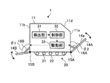
- FIG. 1 is a schematic perspective view of an amphibious vehicle according to an embodiment of the present invention.
- FIG. 2 is a side view of the amphibious vehicle according to the embodiment of the present invention.
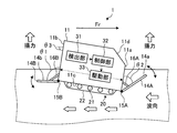
- FIG. 3A is an explanatory diagram of a vehicle body posture at the time of water sailing at a low speed of the amphibious vehicle according to the embodiment of the present invention.
- FIG. 3B is an explanatory diagram of a vehicle body posture at the time of water sailing at a medium speed of an amphibious vehicle according to the embodiment of the present invention.
- FIG. 3C is an explanatory diagram of a vehicle body posture at the time of water-based sailing at a high speed of the amphibious vehicle according to the embodiment of the present invention.
- FIG. 3A is an explanatory diagram of a vehicle body posture at the time of water sailing at a low speed of the amphibious vehicle according to the embodiment of the present invention.
- FIG. 3B is an explanatory diagram of a vehicle body posture at the time of water sailing at a
- FIG. 4 is a flowchart showing an example of a vehicle body attitude control method for an amphibious vehicle according to the first embodiment of the present invention.
- FIG. 5 is an explanatory diagram of the relationship between the vehicle speed and the initial trim angle of the amphibious vehicle according to the first embodiment of the present invention.
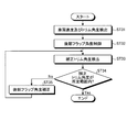
- FIG. 6 is a flowchart showing an example of a vehicle body attitude control method for an amphibious vehicle according to the second embodiment of the present invention.
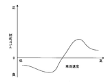
- FIG. 7 is a diagram illustrating an example of a relationship between the vehicle speed acquired in advance and the optimum angle of the trim angle of the amphibious vehicle according to the second embodiment of the present invention.
- FIG. 8 is a diagram showing an example of the relationship between the trim angle and the flap angle of an amphibious vehicle according to the second embodiment of the present invention.
- FIG. 1 is a schematic perspective view of an amphibious vehicle 1 according to an embodiment of the present invention.
- FIG. 2 is a side view of the amphibious vehicle 1 according to the embodiment of the present invention.
- an amphibious vehicle 1 according to the present embodiment includes a vehicle main body 11 having a smooth bottom surface 11 c having a substantially rectangular parallelepiped shape, and a traveling device provided at a lower portion of the vehicle main body 11. 20.
- the vehicle main body 11 is provided with a water propulsion device (not shown) provided with a propeller or a water jet used in the water navigation mode.
- the traveling device 20 includes a sprocket 21 that is rotationally driven by a driving device (not shown) such as an engine, and a crawler belt 22 that is rotationally driven by the sprocket 21.
- a vehicle window 13 is provided on the front surface 11 a in the traveling direction Fr of the amphibious vehicle 1.
- the example which drives the vehicle main body 11 with the traveling apparatus 20 which has the crawler belt 22 was demonstrated in FIG. 1, it may replace with the crawler belt 22 and may use the traveling apparatus which has a tire.
- the front flap 14A is fixed to the lower end of the front surface 11a of the vehicle body 11.
- the front flap 14A is attached to the lower end of the front surface 11a of the vehicle body 11 via a hinge 15A so that the main surface 14a is inclined with respect to the front surface 11a of the vehicle body 11.
- the front flap 14A is configured such that the main surface 14a forms a predetermined flap angle ⁇ 1 with the front surface 11a of the vehicle body 11 via an extendable support member 16A having one end fixed to the lower end of the vehicle body 11. It is attached.
- the support member 16 ⁇ / b> A is provided to be extendable in the front-rear direction in the traveling direction of the vehicle body 11.
- one end of the rear flap 14B is fixed to the lower end of the rear surface 11b of the vehicle body 11.
- the rear flap 14B is attached to the lower end of the rear surface 11b of the vehicle main body 11 via a hinge 15B so that the main surface 14b is inclined with respect to the rear surface 11b of the vehicle main body 11.
- the rear flap 14B has a predetermined flap angle ⁇ 1 between the main surface 14b and the rear surface 11b of the vehicle body 11 via an extendable support member 16B having one end fixed to the lower end of the vehicle body 11 (see FIG. 2). It is attached to make.
- the front flap 14A is rotatably attached to the lower end portion of the front surface 11a of the vehicle main body 11, and the rear flap 14B is rotatable to the lower end portion of the rear surface 11b of the vehicle main body 11.
- the front flap 14A and the rear flap 14B are not limited to this configuration.
- the front flap 14 ⁇ / b> A may be provided on the front surface 11 a side of the vehicle main body 11, and is not necessarily fixed to the lower end portion of the front surface 11 a of the vehicle main body 11.
- the rear flap 14 ⁇ / b> B only needs to be provided on the rear surface 11 b side of the vehicle main body 11, and is not necessarily fixed to the lower end portion of the rear surface 11 b of the vehicle main body 11.
- the rear flap 14B may be installed near the rear end of the bottom surface 11c of the vehicle body 11.
- the amphibious vehicle 1 includes a detection unit 31 that detects a flap angle ⁇ 1 between the rear surface 11b of the vehicle main body 11 and the rear flap 14B, and a rear surface of the vehicle main body 11 based on the flap angle ⁇ 1 detected by the detection unit 31. 11b and the flap flap .theta.1 between the rear flap 14B, and the front flap 14A and the rear flap 14B are driven and rotated so that the flap angle .theta.1 calculated by the controller 32 is obtained.
- a drive unit 33 is provided.
- the detecting unit 31 is not particularly limited as long as the effect of the present invention is achieved.
- the trim angle ⁇ 3 is an angle indicating the inclination of the vehicle body 11 with respect to the horizontal direction.
- the drive unit 33 is not particularly limited as long as the effect of the present invention is achieved, and various actuators can be used, for example.
- the rear flap 14B on the rear surface 11b side of the vehicle main body 11 is fixed so as to be rotatable relative to the rear surface 11b of the vehicle main body 11 via the hinge 15B.
- the rear flap 14B is configured to be fixable to the rear surface 11b of the vehicle main body 11 by a fixing member (not shown).
- the rear flap 14B may drive the hinge 15B by the driving unit 33 to fix the main surface 14b to the rear surface 11b of the vehicle body 11 so as to be rotatable, and the driving unit 33 drives the support member 16B. Then, the main surface 14b may be rotatably fixed to the rear surface 11b of the vehicle body 11.
- the detection unit 31 detects the flap angle ⁇ 1 at any time during a watercraft run, and the detected flap angle ⁇ 1 is input to the control unit 32.
- the control unit 32 determines whether or not the flap angle ⁇ 1 detected by the detection unit 31 is within a predetermined range set in advance according to the traveling speed.
- the control unit 32 calculates a deviation necessary for the flap angle ⁇ 1 to be within the preset range, and the calculated deviation is the drive unit 33. Is input.
- the drive unit 33 drives the support member 16B to rotate the rear flap 14B with the hinge 15B as a fulcrum so that the flap angle ⁇ 1 is within a preset range.
- the amphibious vehicle 1 can maintain the vehicle body posture in an appropriate state according to the speed.
- the drive unit 33 drives the support member 16B to rotate the rear flap 14B.
- the drive unit 33 rotates the hinge 15B to rotate the rear flap 14B. There is no restriction on the specific driving method because it can be moved.
- FIG. 3A is an explanatory diagram of the vehicle body posture when the amphibious vehicle 1 is running on the water at low speed
- FIG. 3B is an explanatory diagram of the vehicle body posture when the amphibious vehicle 1 is running on the water at a medium speed
- FIG. 3C is an explanatory diagram of the vehicle body posture of the amphibious vehicle 1 when the watercraft travels at high speed.
- the amphibious vehicle 1 has a smooth bottom surface 11c of the vehicle body 11 and a shorter overall length of the vehicle body 11 in order to improve the running ability of rough terrain on land. Yes.
- the amphibious vehicle 1 sails on the water at a low speed (for example, 10 km / h or more)
- the vehicle body 11 sinks while the trim angle ⁇ 3 sinks in front of the vehicle body 11. Tilt forward.
- a low speed for example, 10 km / h or more
- the amphibious vehicle 1 when the speed of the amphibious vehicle 1 reaches a medium speed (for example, 15 km / h or more and 25 km / h or less), the amphibian wave on the front side of the vehicle body 11 causes the vehicle body 11 to A large water pressure acts on the front side, the front side of the vehicle body 11 rises and the rear side sinks, and the trim angle ⁇ 3 of the vehicle body 11 greatly increases in the direction in which the front side of the vehicle body 11 is lifted. Furthermore, as shown in FIG. 3C, the amphibious vehicle 1 is in a sliding state in which the dynamic lifting force acts on the bottom surface 11c of the vehicle main body 11 and the vehicle main body 11 floats when the speed becomes high (for example, 25 km / h or more).
- a medium speed for example, 15 km / h or more and 25 km / h or less
- the trim angle ⁇ 3 of the vehicle body 11 decreases.
- the change in the trim angle ⁇ 3 corresponding to the change in the traveling speed of the vehicle main body 11 during the water navigation becomes large.
- the present inventors paid attention to the relationship between the vehicle speed of the amphibious vehicle 1 and the flap angle and trim angle ⁇ 3 of the rear flap 14B. Then, the present inventors control the angle of the rear flap 14B in accordance with the vehicle speed when the amphibious vehicle 1 is running on the water, thereby setting the trim angle ⁇ 3 of the amphibious vehicle 1 within an appropriate range. It was found that the body posture of 1 could be controlled.
- the vehicle body attitude control method of the amphibious vehicle 1 according to the present embodiment will be described in detail.
- the vehicle body attitude control method for the amphibious vehicle 1 includes a first step of detecting the vehicle speed of the vehicle body 11, the detected vehicle speed, the vehicle speed acquired in advance, and the vehicle body 11. And a second step of controlling the flap angle ⁇ 2 based on the relationship with the optimum angle of the flap angle ⁇ 1 of the rear flap 14B provided at the rear portion.
- FIG. 4 is a flowchart showing an example of a vehicle body attitude control method for the amphibious vehicle 1 according to the first embodiment of the present invention.
- the control unit 32 detects the vehicle speed of the amphibious vehicle 1 via the detection unit 31 (step ST11). Based on the detected vehicle speed, the flap angle ⁇ 1 of the rear flap 14B is controlled via the drive unit 33 (step ST12).
- the control unit 32 controls the flap angle ⁇ 1 by outputting an output signal to the drive unit 33 based on the map of the relationship between the vehicle speed of the amphibious vehicle 1 and the optimum angle of the flap angle ⁇ 1 acquired in advance.
- the control unit 32 detects the flap angle ⁇ 1 of the rear flap 14B via the detection unit 31 (step ST13), and determines whether or not the detected flap angle ⁇ 1 is within a predetermined range of the target value of the map described above. (Step ST14). As a result, when the detected flap angle ⁇ 1 of the rear flap 14B is not within the predetermined range (step ST14: No), the control unit 32 obtains the deviation from the target value of the flap angle ⁇ 1 described above and controls the drive unit 33. The flap angle ⁇ 1 of the rear flap 14B is corrected so as to be within the predetermined range of the map described above (step ST15).
- the control unit 32 ends the control of the flap angle ⁇ 1.
- the amphibious vehicle is controlled by controlling the flap angle ⁇ 1 based on the relationship between the vehicle speed of the amphibious vehicle 1 acquired in advance and the optimum angle of the flap angle ⁇ 1 of the rear flap 14B. Even when the vehicle speed of the vehicle 1 changes, the trim angle ⁇ 3 can be set within a predetermined range according to the vehicle speed, so that the vehicle body posture of the amphibious vehicle 1 is in an appropriate cruising trim state according to the speed. Can be kept in.
- the control unit 32 detects an initial trim angle that is a trim angle ⁇ 3 in a stationary state when the amphibious vehicle 1 departs on the water via the detection unit 31. Next, the control unit 32 prepares a plurality of curves corresponding to different initial trim angles in advance in a map of the relationship between the vehicle speed of the amphibious vehicle 1 and the optimum angle of the flap angle ⁇ 1 (see FIG. 5). Alternatively, using the measured initial trim angle, an optimal vehicle speed corresponding to the initial trim and the curve of the flap angle ⁇ 1 may be interpolated from the plurality of curves.
- the map of the vehicle speed and the optimum angle of the flap angle ⁇ 1 of the rear flap 14 ⁇ / b> B changes according to the initial trim angle based on the vehicle characteristics corresponding to the shape of the vehicle main body 11 and the change in the center of gravity due to the load. .
- the flap angle ⁇ 1 of the rear flap 14B is large.
- the flap angle ⁇ 1 of the rear flap 14B tends to be small.
- the vehicle body attitude control method for an amphibious vehicle 1 includes a first step of detecting a vehicle speed and a trim angle ⁇ 3 of the vehicle body 11, a detected vehicle speed, and a previously acquired vehicle speed. And a second step of controlling the flap angle ⁇ 1 of the rear flap 14B provided at the rear portion of the vehicle body 11 based on the relationship between the trim angle ⁇ 3 and the optimum angle of the trim angle ⁇ 3.
- FIG. 6 is a flowchart showing an example of a vehicle body attitude control method for the amphibious vehicle 1 according to the second embodiment of the present invention.
- the control unit 32 detects the vehicle speed and the trim angle ⁇ 3 of the amphibious vehicle 1 via the detection unit 31 ( Step ST31), based on the detected vehicle speed and trim angle ⁇ 3, the flap angle ⁇ 1 of the rear flap 14B is controlled via the drive unit 33 (step ST32).
- the control unit 32 performs the signal processing such as A / D conversion on the output signal based on the previously acquired map of the relationship between the vehicle speed of the amphibious vehicle 1 and the optimum angle of the flap angle ⁇ 1.
- step ST34 Yes
- the control unit 32 does not change the flap angle ⁇ 1 and changes the flap angle ⁇ 1. End the control.
- the control unit 32 determines the rear flap 14B via the drive unit 33 based on the relationship between the vehicle speed acquired in advance and the optimum angle of the trim angle ⁇ 3 and the relationship between the trim angle ⁇ 3 and the flap angle ⁇ 1.
- the flap angle ⁇ 1 is controlled.
- FIG. 7 is a diagram showing an example of the relationship between the vehicle speed acquired in advance and the optimum angle of the trim angle ⁇ 3 when sailing at the same speed, and FIG. 8 is necessary for changing the trim angle ⁇ 3 by ⁇ 3. It is a figure which shows an example of displacement amount (DELTA) (theta) 1 of flap angle. As shown in FIG.
- DELTA displacement amount
- the vehicle body is obtained by previously acquiring the relationship between the vehicle speed of the amphibious vehicle 1 and the optimum angle of the trim angle ⁇ 3, and controlling the flap angle ⁇ 1 of the rear flap 14B.
- 1 trim angle ⁇ 3 can be set within a predetermined range with respect to the optimum angle.
- the control unit 32 issues an angle change command for controlling the increase / decrease in the flap angle, the previously obtained trim angle displacement amount ⁇ 3 and the flap angle displacement amount ⁇ 1 of the rear flap 14B are obtained.
- the flap angle ⁇ 1 of the rear flap 14B can be easily adjusted within a range where the optimum angle of the trim angle ⁇ 3 can be obtained. It becomes possible to do.
- the average relationship here includes, for example, the value of the displacement amount ⁇ 1 of the flap angle of the rear flap 14B with respect to the displacement amounts ⁇ 3 of the plurality of trim angles ⁇ 3 acquired in advance, but is not limited thereto. .
- the control unit 32 detects the corrected correction trim angle ⁇ 3 of the vehicle body 11 after the control of the flap angle ⁇ 1 of the rear flap 14B via the detection unit 31 (step ST33), and the detected correction trim angle ⁇ 3. Is determined to be within a predetermined range of the target value of the map described above (step ST34). As a result, when the detected trim angle ⁇ 3 of the vehicle main body 11 is not within the predetermined range (step ST34: No), the control unit 32 obtains a deviation from the target value of the trim angle ⁇ 3 described above and controls the drive unit 33. Then, the flap angle ⁇ 1 of the rear flap 14B is driven to correct the trim angle ⁇ 3 of the vehicle body 11 to be within the predetermined range of the map described above (step ST35).
- the control unit 32 ends the control of the flap angle ⁇ 1.
- the amphibious vehicle is controlled by controlling the flap angle ⁇ 1 based on the relationship between the vehicle speed of the amphibious vehicle 1 acquired in advance and the optimum angle of the trim angle ⁇ 3 of the vehicle body 11. Even when the vehicle speed of the vehicle 1 changes, the trim angle ⁇ 3 can be set within a predetermined range according to the vehicle speed, so that the vehicle body posture of the amphibious vehicle 1 is maintained in an appropriate state according to the speed. Can do.
- the trim angle ⁇ 3, the vehicle speed, and the flap angle ⁇ 1 can be detected and the flap angle can be appropriately controlled at the time of surface water travel.
- the flap angle can be appropriately controlled at the time of surface water travel.
- the amphibious vehicle 1 can reduce the fluid resistance at the time of surface water travel, it becomes possible to improve the propulsion performance of the vehicle body 11 such as speed improvement at the time of surface water travel.
- the front flap 14A and the rear flap 14B Alternatively, as long as the main surfaces 14a and 14b can be maintained at the predetermined flap angles ⁇ 1 and ⁇ 2 with respect to the rear surface 11b, the hinges 15A and 15B are not necessarily fixed. Furthermore, in the present embodiment, the example in which the front flap 14A and the rear flap 14B are fixed to the vehicle body 11 by the support members 16A and 16B has been described. However, the front flap 14A and the rear flap 14B are not necessarily the support member 16A. , 16B need not be fixed to the vehicle body 11.
- the example in which the front flap 14A is configured by a single plate member is shown, but it may be configured by a plurality of plate materials such as a lower flap and an upper flap.
- the map for flap angle control shown in FIGS. 5, 7, and 8 is prepared for each drainage amount of the land and land vehicle, or a map for a predetermined drainage amount is prepared using the prepared map group for each drainage amount. It is preferable to calculate by interpolation.
- the amphibious vehicle 1 detects the flap angle ⁇ 2 between the front surface 11a of the vehicle body 11 and the front flap 14A by the detection unit 31, and based on the detected flap angle ⁇ 2, the front surface 11a of the vehicle body 11 and the front
- the flap angle ⁇ 2 between the rear flap 14A and the rear flap 14A is controlled by the control unit 32, and the rear flap 14B can be driven and rotated by the drive unit 33 so that the flap angle ⁇ 2 calculated by the control unit 32 is obtained.
Landscapes
- Engineering & Computer Science (AREA)
- Chemical & Material Sciences (AREA)
- Combustion & Propulsion (AREA)
- Transportation (AREA)
- Mechanical Engineering (AREA)
- Body Structure For Vehicles (AREA)
- Electric Propulsion And Braking For Vehicles (AREA)
Abstract
水上航走時の流体抵抗を低減でき、車両本体の推進性能を向上できる水陸両用車及び水陸両用車の車体姿勢制御方法を提供すること。本発明の水陸両用車1は、水上及び陸上を移動可能な車両本体11と、前記車両本体11の後部に設けられた後部フラップ14Bと、後部フラップ14Bを駆動して車両本体11と後部フラップ14Bとの間のフラップ角度θ1を変化させる駆動部33と、車両本体11のトリム角度、車両速度及びフラップ角度θ1を検出する検出部31と、検出部31が検出したトリム角度、車両速度及びフラップ角度θ1に基づいて、フラップ角度θ1を制御する制御部32とを備えたことを特徴とする。
Description
本発明は、水陸両用車及び水陸両用車の車体姿勢制御方法に関し、例えば、車両本体の後部に板状部材が設けられた水陸両用車及び水陸両用車の車体姿勢制御方法に関する。
従来、トランサム船尾構造を有する船舶のトランサムの没水した下端にフラップが設けられた船尾フラップ装置が提案されている(例えば、特許文献1参照)。この船尾フラップ装置においては、船舶の航行速度に対応して搖動機構によってフラップ角度を制御することにより、船舶の航行に伴う燃料消費量を低減することが可能となる。
ところで、水陸両用車においては、陸上での不整地の走破性を向上するために、車両底面の形状を平滑にすると共に、車両本体の全長が短くされる。このような水陸両用車においては、水上航走時に低速では車両本体が前傾し、中速では車両本体の船首造波により車両本体が後傾し、高速では車両本体の底面に動的揚力が作用して車両本体の傾きが減少する。このように、従来の水陸両用車においては、水上航走時の速度の変化に応じて車両本体のトリム角度の変化が大きくなるので、トリム角度を適切に制御して水上航走時の車両本体への水による流体抵抗の影響を低減できる技術が望まれている。
本発明は、このような実情に鑑みてなされたものであり、水上航走時の流体抵抗を低減でき、車両本体の推進性能を向上できる水陸両用車及び水陸両用車の車体姿勢制御方法を提供することを目的とする。
本発明の水陸両用車は、水上及び陸上を移動可能な車両本体と、前記車両本体の後部に設けられた後部フラップと、前記後部フラップを駆動して前記車両本体と前記後部フラップとの間のフラップ角度を変化させる駆動部と、前記車両本体のトリム角度、車両速度及び前記フラップ角度を検出する検出部と、前記検出部が検出した前記トリム角度、前記車両速度及び前記フラップ角度に基づいて、前記フラップ角度を制御する制御部とを備えたことを特徴とする。
この水陸両用車によれば、水上航走時にトリム角度、車両速度及びフラップ角度を検出してフラップ角度を適切に制御できるので、水上航走時に車体姿勢を適切に制御することが可能となる。これにより、水陸両用車は、水上航走時の流体抵抗を低減することが可能となるので、水上航走時の速度向上など車両本体の推進性能を向上することが可能となる。
本発明の水陸両用車においては、前記制御部は、予め取得した前記車両速度と前記フラップ角度の最適角度との関係に基づいて前記フラップ角度を制御することが好ましい。この構成により、水陸両用車は、フラップ角度を車両速度に応じた最適角度に向けて制御することができるので、水上航走時に車体姿勢をより一層適切に制御することが可能となる。
本発明の水陸両用車においては、前記制御部は、前記車両本体の静止状態でのトリム角度(以下、初期トリム角度と称する)を検出し、検出した初期トリム角度に対応する予め取得した前記車両速度と前期フラップ角度の最適角度との関係に基づいて前記フラップ角度を制御することが好ましい。この構成により、水陸両用車は、車両本体の車両特性に応じた初期トリム角度に対応した最適フラップ角度に向けて制御することができるので、水上航走時に車体姿勢をより一層適切に制御することが可能となる。
本発明の水陸両用車においては、前記制御部は、予め取得した前記車両速度と前記トリム角度の最適角度との関係に基づいて前記フラップ角度を制御することが好ましい。この構成により、水陸両用車は、フラップ角度を車両速度に応じたトリム角度の最適角度に向けて制御することができるので、水上航走時に車体姿勢をより一層適切に制御することが可能となる。
本発明の水陸両用車においては、前記制御部は、予め取得した前記トリム角度の変位量と前記フラップ角度の変位量との平均的な関係に基づいて前記フラップ角度の増減を制御するためのフラップ角度の変位量を算定する機能を有することが好ましい。この構成により、水陸両用車は、フラップ角度を車両速度に応じたトリム角度の最適角度に向けて制御することがより容易に出来るので、水上航走時に車体姿勢をより一層適切に制御することが可能となる。
本発明の水陸両用車の車体姿勢制御方法は、車両本体の車両速度を検出する第1ステップと、検出した前記車両速度及び予め取得した前記車両速度と車両本体の後部に設けられた後部フラップのフラップ角度の最適角度との関係に基づいて前記フラップ角度を制御する第2ステップとを含むことを特徴とする。
この水陸両用車の車体姿勢の制御方法によれば、フラップ角度を車両速度に応じた最適角度に向けて制御することができるので、水上航走時に車体姿勢を適切に制御することが可能となる。これにより、水陸両用車の車体姿勢の制御方法は、水上航走時の流体抵抗を低減することが可能となるので、水上航走時の速度向上など車両本体の推進性能を向上することが可能となる。
本発明の水陸両用車の車体姿勢制御方法は、車両本体の車両速度及びトリム角度を検出する第1ステップと、検出した前記車両速度及び予め取得した前記車両速度と前記トリム角度の最適角度との関係に基づいて前記車両本体の後部に設けられた後部フラップのフラップ角度を制御する第2ステップとを含むことを特徴とする。
この水陸両用車の車体姿勢の制御方法によれば、フラップ角度を車両速度に応じたトリム角度の最適角度に向けて制御することができるので、水上航走時に車体姿勢を適切に制御することが可能となる。これにより、水陸両用車の車体姿勢の制御方法は、水上航走時の流体抵抗を低減することが可能となるので、水上航走時の速度向上など車両本体の推進性能を向上することが可能となる。
本発明によれば、水上航走時の流体抵抗を低減でき、車両本体の推進性能を向上できる水陸両用車及び水陸両用車の車体姿勢制御方法を実現できる。
以下、本発明の一実施の形態について、添付図面を参照して詳細に説明する。なお、以下の各実施の形態に限定されるものではなく、適宜変更して実施可能である。また、以下の各実施の形態は適宜組み合わせて実施可能である。また、各実施の形態において共通する構成要素には同一の符号を付し、説明の重複を避ける。
図1は、本発明の実施の形態に係る水陸両用車1の模式的な斜視図である。図2は、本発明の実施の形態に係る水陸両用車1の側面図である。図1及び図2に示すように、本実施の形態に係る水陸両用車1は、概略直方体形状をなす平滑な底面11cを有する車両本体11と、この車両本体11の下部に設けられた走行装置20とを備える。車両本体11には、水上航走モードで使用するプロペラ又はウォータジェットを備えた水上推進器(不図示)が設けられている。走行装置20は、エンジンなどの駆動装置(不図示)により回転駆動されるスプロケット21と、このスプロケット21により回転駆動される履帯22とを備える。この水陸両用車1の走行方向Frにおける前面11aには車窓13が設けられている。なお、図1においては、履帯22を有する走行装置20によって車両本体11を駆動する例について説明したが、履帯22に代えてタイヤを有する走行装置を用いてもよい。
車両本体11の前面11aの下端部には前部フラップ14Aの一端部が固定されている。この前部フラップ14Aは、車両本体11の前面11aに対して主面14aが傾斜するように、ヒンジ15Aを介して車両本体11の前面11aの下端部に取り付けられている。前部フラップ14Aは、車両本体11の下端部に一端が固定された伸縮可能な支持部材16Aを介して車両本体11の前面11aとの間で主面14aが所定のフラップ角度θ1をなすように取り付けられている。支持部材16Aは、車両本体11の進行方向における前後方向に伸縮可能に設けられている。
また、車両本体11の後面11bの下端部には、後部フラップ14Bの一端部が固定されている。この後部フラップ14Bは、車両本体11の後面11bに対して主面14bが傾斜するように、ヒンジ15Bを介して車両本体11の後面11bの下端部に取り付けられている。後部フラップ14Bは、車両本体11の下端部に一端が固定された伸縮可能な支持部材16Bを介して車両本体11の後面11bとの間で主面14bが所定のフラップ角度θ1(図2参照)をなすように取り付けられている。
なお、上述した実施の形態においては、前部フラップ14Aが車両本体11の前面11aの下端部に回動可能に取り付けられ、後部フラップ14Bが車両本体11の後面11bの下端部に回動可能に取り付けられた例について説明したが、前部フラップ14A及び後部フラップ14Bは、この構成に限定されない。前部フラップ14Aは、車両本体11の前面11a側に設けられるものであればよく、必ずしも車両本体11の前面11aの下端部に固定される必要はない。同様に、後部フラップ14Bは、車両本体11の後面11b側に設けられるものであればよく、必ずしも車両本体11の後面11bの下端部に固定される必要はない。なお、後部フラップ14Bは、車両本体11の底面11cの後端付近に設置してもかまわない。
また、水陸両用車1は、車両本体11の後面11bと後部フラップ14Bとの間のフラップ角度θ1を検出する検出部31と、検出部31が検出したフラップ角度θ1に基づいて車両本体11の後面11bと後部フラップ14Bとの間のフラップ角度θ1を制御する制御部32と、制御部32によって算出されたフラップ角度θ1となるように、前部フラップ14A及び後部フラップ14Bを駆動して回動させる駆動部33を備える。検出部31としては、本発明の効果を奏する範囲であれば特に制限はなく、車両本体11に作用するピッチング方向のトリム角度θ3を検出する各種角度センサ、車両速度を検出するドップラスピードログやGPSなどによる船速計、車両本体11のトリム角度θ3を検出するジャイロなど又は傾斜計などを備えたものを用いることができる。なお、ここでのトリム角度θ3とは、水平方向に対する車両本体11の傾きを示す角度である。駆動部33としては、本発明の効果を奏する範囲であれば特に制限はなく、例えば、各種アクチュエータなどを用いることができる。
また、水陸両用車1は、車両本体11の後面11b側の後部フラップ14Bが、ヒンジ15Bを介して車両本体11の後面11bに対して相対的に回動可能に固定されている。後部フラップ14Bは、固定部材(不図示)によって車両本体11の後面11bに固定可能に構成されている。なお、後部フラップ14Bは、駆動部33によってヒンジ15Bを駆動して車両本体11の後面11bに対して主面14bを回動可能に固定してもよく、また駆動部33によって支持部材16Bを駆動して車両本体11の後面11bに対して主面14bを回動可能に固定してもよい。
この水陸両用車1においては、検出部31は、水上航走時にはフラップ角度θ1を随時検出し、検出したフラップ角度θ1が制御部32に入力される。制御部32は、検出部31により検出したフラップ角度θ1が航走速度に応じて予め設定された所定範囲内であるか否かを判定する。そして、制御部32は、フラップ角度θ1が予め設定された範囲外の場合には、フラップ角度θ1が予め設定された範囲内となるために必要な偏差を算出し、算出した偏差が駆動部33に入力される。駆動部33は、支持部材16Bを駆動してヒンジ15Bを支点として後部フラップ14Bを回動させてフラップ角度θ1が予め設定された範囲内とされる。このように制御することにより、水陸両用車1は、車体姿勢を速度に応じた適切な状態に保つことができる。なお、上述した実施の形態では、駆動部33が支持部材16Bを駆動して後部フラップ14Bを回動させる例について説明したが、駆動部33は、ヒンジ15Bを回動させて後部フラップ14Bを回動させれば良いので、その具体的な駆動方法についての制限はない。
次に、図3A~図3Cを参照して水陸両用車1の水上航走時の車体姿勢について説明する。図3Aは、水陸両用車1の低速での水上航走時の車体姿勢の説明図であり、図3Bは、水陸両用車1の中速での水上航走時の車体姿勢の説明図であり、図3Cは、水陸両用車1の高速での水上航走時の車体姿勢の説明図である。
図3Aに示すように、水陸両用車1は、陸上での不整地の走破性を向上するために、車両本体11の底面11cの形状を平滑にすると共に、車両本体11の全長が短くされている。図3Aに示すように、水陸両用車1の水上航走時の航行姿勢は、低速(例えば、10km/h以上)では、車両本体11が沈降しつつトリム角度θ3は車両本体11の前方が沈下する方向に前傾する。また、図3Bに示すように、水陸両用車1は、速度が中速(例えば、15km/h以上25km/h以下)になると、車両本体11の前部側における船首造波により車両本体11の前方側に大きな水圧が作用して、車両本体11の前部側が浮き上がると共に後部側が沈み込む状態となり、車両本体11のトリム角度θ3は車両本体11の前方側が持ち上がる方向に大幅に増大する。さらに、図3Cに示すように、水陸両用車1は、速度が高速(例えば、25km/h以上)になると車両本体11の底面11cに動的揚力が作用して車両本体11が浮上する滑走状態となり、車両本体11のトリム角度θ3が減少する。このように、車両本体11の底面11cが平滑で全長が短い水陸両用車1においては、水上航走時の車両本体11の航走速力の変化に応じたトリム角度θ3の変化が大きくなる。
そこで、本発明者らは、水陸両用車1の車両速度と後部フラップ14Bのフラップ角度及びトリム角度θ3との関係に着目した。そして、本発明者らは、水陸両用車1の水上航走時の車両速度に応じて後部フラップ14Bの角度を制御することにより、水陸両用車1のトリム角度θ3を適切な範囲として水陸両用車1の車体姿勢を制御できることを見出した。以下、本実施の形態に係る水陸両用車1の車体姿勢制御方法について詳細に説明する。
本発明の第1の実施の形態に係る水陸両用車1の車体姿勢制御方法は、車両本体11の車両速度を検出する第1ステップと、検出した車両速度及び予め取得した車両速度と車両本体11の後部に設けられた後部フラップ14Bのフラップ角度θ1の最適角度との関係に基づいてフラップ角度θ2を制御する第2ステップとを含む。
図4は、本発明の第1の実施の形態に係る水陸両用車1の車体姿勢制御方法の一例を示すフロー図である。図4に示すように、本実施の形態に係る水陸両用車1の車体姿勢制御方法では、制御部32は、検出部31を介して水陸両用車1の車両速度を検出し(ステップST11)、検出した車両速度に基づいて駆動部33を介して後部フラップ14Bのフラップ角度θ1を制御する(ステップST12)。ここでは、制御部32は、予め取得した水陸両用車1の車両速度とフラップ角度θ1の最適角度との関係のマップに基づいた出力信号を駆動部33に出力してフラップ角度θ1を制御する。次に、制御部32は、検出部31を介して後部フラップ14Bのフラップ角度θ1を検出し(ステップST13)、検出したフラップ角度θ1が上述したマップの目標値の所定範囲内か否かを判定する(ステップST14)。その結果、制御部32は、検出した後部フラップ14Bのフラップ角度θ1が所定範囲内でない場合(ステップST14:No)には、上述したフラップ角度θ1の目標値との偏差を求めて駆動部33を介して後部フラップ14Bのフラップ角度θ1を上述したマップの所定範囲内となるように補正する(ステップST15)。また、制御部32は、検出した後部フラップ14Bのフラップ角度θ1が所定範囲内の場合(ステップST14:Yes)には、フラップ角度θ1の制御を終了する。このように、本実施の形態においては、予め取得した水陸両用車1の車両速度と後部フラップ14Bのフラップ角度θ1の最適角度との関係に基づいてフラップ角度θ1を制御することにより、水陸両用車1の車両速度が変化した場合であっても、トリム角度θ3を車両速度に応じた所定範囲内とすることができるので、水陸両用車1の車体姿勢を速度に応じた適切な航走トリム状態に保つことができる。
なお、図4に示した例においては、以下のようにしてもよい。制御部32は、検出部31を介して水陸両用車1の水上への出航時に静止状態のトリム角度θ3である初期トリム角度を検知する。次に、制御部32は、水陸両用車1の車両速度とフラップ角度θ1の最適角度との関係のマップ(図5参照)において、予め異なる初期トリム角度に対応する複数のカーブを用意しておき、計測された初期トリム角度を用いて当該複数のカーブから初期トリムに対応する最適な車両速度とフラップ角度θ1のカーブを内挿して求めてもよい。水陸両用車1は、車両本体11の形状及び積荷等による重心位置変化などに応じた車両特性による初期トリム角度に応じて車両速度と後部フラップ14Bのフラップ角度θ1の最適角度とのマップが変化する。図5に示す例では、初期トリム角度がない場合(図5の実線L1参照)に対し、初期トリム角度が大きい場合(図5の点線L2参照)では、後部フラップ14Bのフラップ角度θ1が大きくなる傾向となり、初期トリム角度が小さい場合(図5の一点鎖線L3参照)では、後部フラップ14Bのフラップ角度θ1が小さくなる傾向となる。このように制御することにより、水陸両用車1の車体姿勢を速度に応じたより一層適切な航走トリム状態に保つことができる。
本発明の第2の実施の形態に係る水陸両用車1の車体姿勢制御方法は、車両本体11の車両速度及びトリム角度θ3を検出する第1ステップと、検出した車両速度及び予め取得した車両速度とトリム角度θ3の最適角度との関係に基づいて車両本体11の後部に設けられた後部フラップ14Bのフラップ角度θ1を制御する第2ステップとを含む。
図6は、本発明の第2の実施の形態に係る水陸両用車1の車体姿勢制御方法の一例を示すフロー図である。図6に示すように、本実施の形態に係る水陸両用車1の車体姿勢制御方法では、制御部32は、検出部31を介して水陸両用車1の車両速度及びトリム角度θ3を検出し(ステップST31)、検出した車両速度及びトリム角度θ3に基づいて駆動部33を介して後部フラップ14Bのフラップ角度θ1を制御する(ステップST32)。ここでは、制御部32は、予め取得した水陸両用車1の車両速度とフラップ角度θ1の最適角度との関係のマップに基づいた出力信号をA/D変換などの信号処理を実行した後に駆動部33に出力してフラップ角度θ1を制御する。なお、ここでは、制御部32は、検出した車両本体11のトリム角度θ3が最適角度の所定範囲内の場合(ステップST34:Yes)には、フラップ角度θ1の角度を変更せずにフラップ角度θ1の制御を終了する。
本実施の形態においては、制御部32は、予め取得した車両速度とトリム角度θ3の最適角度との関係及びトリム角度θ3とフラップ角度θ1との関係に基づいて駆動部33を介して後部フラップ14Bのフラップ角度θ1を制御する。図7は、予め取得した車両速度と同速度における航走時のトリム角度θ3の最適角度との関係の一例を示す図であり、図8は、トリム角度θ3をΔθ3だけ変更させるのに必要なフラップ角度の変位量Δθ1の一例を示す図である。図7に示すように、本実施の形態では、水陸両用車1の車両速度とトリム角度θ3の最適角度との関係を予め取得し、後部フラップ14Bのフラップ角度θ1を制御することにより、車両本体1のトリム角度θ3を最適角度に対する所定範囲内とすることが可能となる。図8に示すように、制御部32が、フラップ角度の増減を制御するための角度変更指令を出す際、予め取得したトリム角度の変位量Δθ3と後部フラップ14Bのフラップ角度の変位量Δθ1との平均的な関係を用いてフラップ角度の増減を制御するための角度変更指令を算定する機能を有することで、トリム角度θ3の最適角度が得られる範囲に後部フラップ14Bのフラップ角度θ1を容易に調整することが可能となる。ここでの平均的な関係とは、例えば、予め取得した複数のトリム角度θ3の変位量Δθ3に対する後部フラップ14Bのフラップ角度の変位量Δθ1の値が挙げられるが、これに制限されるものではない。
次に、制御部32は、検出部31を介して後部フラップ14Bのフラップ角度θ1の制御後の車両本体11の補正された補正トリム角度θ3を検出し(ステップST33)、検出した補正トリム角度θ3が上述したマップの目標値の所定範囲内か否かを判定する(ステップST34)。その結果、制御部32は、検出した車両本体11のトリム角度θ3が所定範囲内でない場合(ステップST34:No)には、上述したトリム角度θ3の目標値との偏差を求めて駆動部33を介して後部フラップ14Bのフラップ角度θ1を駆動して車両本体11のトリム角度θ3が上述したマップの所定範囲内となるように補正する(ステップST35)。また、制御部32は、検出した車両本体11のトリム角度θ3が所定範囲内の場合(ステップST34:Yes)には、フラップ角度θ1の制御を終了する。このように、本実施の形態においては、予め取得した水陸両用車1の車両速度と車両本体11のトリム角度θ3の最適角度との関係に基づいてフラップ角度θ1を制御することにより、水陸両用車1の車両速度が変化した場合であっても、トリム角度θ3を車両速度に応じた所定範囲内とすることができるので、水陸両用車1の車体姿勢を速度に応じた適正な状態に保つことができる。
以上説明したように、上記実施の形態に係る水陸両用車1によれば、水上航走時にトリム角度θ3、車両速度及びフラップ角度θ1を検出してフラップ角度を適切に制御できるので、水上航走時に車体姿勢を適切に制御することが可能となる。これにより、水陸両用車1は、水上航走時の流体抵抗を低減することが可能となるので、水上航走時の速度向上など車両本体11の推進性能を向上することが可能となる。
なお、上述した実施の形態では、前部フラップ14A及び後部フラップ14Bとしては、平板状の板状部材を用いる例について説明したが、前部フラップ14A及び後部フラップ14Bの形状としては、本発明の効果を奏する範囲で波板などの平板以外の板状部材に適宜変更可能である。また、前部フラップ14A及び後部フラップ14Bの幅は、本発明の効果を奏する範囲で適宜変更可能である。また、本実施の形態においては、前部フラップ14A及び後部フラップ14Bをヒンジ15A,15Bによって車両本体11に取り付ける例について説明したが、前部フラップ14A及び後部フラップ14Bは、車両本体11の前面11a又は後面11bとの間で主面14a,14bが所定のフラップ角度θ1、θ2の状態に保てるものであれば、必ずしもヒンジ15A,15Bを用いて固定する必要はない。さらに、本実施の形態においては、前部フラップ14A及び後部フラップ14Bを支持部材16A,16Bによって車両本体11に固定する例について説明したが、前部フラップ14A及び後部フラップ14Bは、必ずしも支持部材16A,16Bを介して車両本体11に固定する必要はない。さらに、上述した実施の形態においては、前部フラップ14Aは1つの板上部材によって構成した例を示したが、下部フラップ、上部フラップなど複数の板材によって構成してもよい。この場合、図5、図7、図8に示したフラップ角制御用のマップは、水陸車両の排水量ごとに用意し、又は用意された各排水量毎のマップ群を用いて所定の排水量に対するマップを内挿して算定することが好ましい。
なお、水陸両用車1は、車両本体11の前面11aと前部フラップ14Aとの間のフラップ角度θ2を検出部31で検出し、検出したフラップ角度θ2に基づいて車両本体11の前面11aと前部フラップ14Aとの間のフラップ角度θ2を制御部32で制御し、制御部32によって算出されたフラップ角度θ2となるように、後部フラップ14Bを駆動部33で駆動して回動させることもできる。
1 水陸両用車
11 車両本体
11a 前面
11b 後面
11c 底面
11d 斜面
13 車窓
14A 前部フラップ
14B 後部フラップ
15A,15B ヒンジ
16A,16B 支持部材
20 走行装置
21 スプロケット
22 履帯
31 検出部
32 制御部
33 駆動部
11 車両本体
11a 前面
11b 後面
11c 底面
11d 斜面
13 車窓
14A 前部フラップ
14B 後部フラップ
15A,15B ヒンジ
16A,16B 支持部材
20 走行装置
21 スプロケット
22 履帯
31 検出部
32 制御部
33 駆動部
Claims (7)
- 水上及び陸上を移動可能な車両本体と、
前記車両本体の後部に設けられた後部フラップと、
前記後部フラップを駆動して前記車両本体と前記後部フラップとの間のフラップ角度を変化させる駆動部と、
前記車両本体のトリム角度、車両速度及び前記フラップ角度を検出する検出部と、
前記検出部が検出した前記トリム角度、前記車両速度及び前記フラップ角度に基づいて、前記フラップ角度を制御する制御部とを備えたことを特徴とする、水陸両用車。 - 前記制御部は、予め取得した前記車両速度と前記フラップ角度の最適角度との関係に基づいて前記フラップ角度を制御する、請求項1に記載の水陸両用車。
- 前記制御部は、前記車両本体の初期トリム角度を検出し、検出した初期トリム角度に基づいて前記フラップ角度を制御する、請求項1又は請求項2に記載の水陸両用車。
- 前記制御部は、予め取得した前記車両速度と前記トリム角度の最適角度との関係に基づいて前記フラップ角度を制御する、請求項1から請求項3のいずれか1項に記載の水陸両用車。
- 前記制御部は、予め取得した前記トリム角度の変位量と前記フラップ角度の変位量との平均的な関係に基づいて前記フラップ角度の増減を制御するためのフラップ角度の変位量を算定する機能を有する、請求項4に記載の水陸両用車。
- 車両本体の車両速度を検出する第1ステップと、
検出した前記車両速度及び予め取得した前記車両速度と車両本体の後部に設けられた後部フラップのフラップ角度の最適角度との関係に基づいて前記フラップ角度を制御する第2ステップとを含むことを特徴とする、水陸両用車の車体姿勢制御方法。 - 車両本体の車両速度及びトリム角度を検出する第1ステップと、
検出した前記車両速度及び予め取得した前記車両速度と前記トリム角度の最適角度との関係に基づいて前記車両本体の後部に設けられた後部フラップのフラップ角度を制御する第2ステップとを含むことを特徴とする、水陸両用車の車体姿勢制御方法。
Priority Applications (1)
| Application Number | Priority Date | Filing Date | Title |
|---|---|---|---|
| US15/552,848 US10144257B2 (en) | 2015-02-27 | 2015-11-17 | Amphibious vehicle and method of controlling attitude of vehicle body of amphibious vehicle |
Applications Claiming Priority (2)
| Application Number | Priority Date | Filing Date | Title |
|---|---|---|---|
| JP2015-039567 | 2015-02-27 | ||
| JP2015039567A JP6517047B2 (ja) | 2015-02-27 | 2015-02-27 | 水陸両用車 |
Publications (1)
| Publication Number | Publication Date |
|---|---|
| WO2016136047A1 true WO2016136047A1 (ja) | 2016-09-01 |
Family
ID=56788162
Family Applications (1)
| Application Number | Title | Priority Date | Filing Date |
|---|---|---|---|
| PCT/JP2015/082291 Ceased WO2016136047A1 (ja) | 2015-02-27 | 2015-11-17 | 水陸両用車及び水陸両用車の車体姿勢制御方法 |
Country Status (3)
| Country | Link |
|---|---|
| US (1) | US10144257B2 (ja) |
| JP (1) | JP6517047B2 (ja) |
| WO (1) | WO2016136047A1 (ja) |
Cited By (1)
| Publication number | Priority date | Publication date | Assignee | Title |
|---|---|---|---|---|
| CN111137081A (zh) * | 2020-01-19 | 2020-05-12 | 郑州宇通重工有限公司 | 特种车辆及其滑行板机构 |
Families Citing this family (4)
| Publication number | Priority date | Publication date | Assignee | Title |
|---|---|---|---|---|
| KR102138361B1 (ko) * | 2019-03-29 | 2020-07-27 | 국방과학연구소 | 전방 형상 변형이 가능한 수상주행차량 |
| CN111890856B (zh) * | 2020-08-14 | 2022-07-08 | 天津大学 | 水陆两栖车及其底板补偿与纵倾调节装置 |
| CN113071274B (zh) * | 2021-04-23 | 2021-11-30 | 南京理工大学 | 一种基于混联机构的仿蛙式水陆两栖机器人 |
| CN117021855B (zh) * | 2023-07-25 | 2026-03-24 | 合肥工业大学 | 一种基于控制平稳性考虑的两栖车尾翼板改进pi控制方法 |
Citations (6)
| Publication number | Priority date | Publication date | Assignee | Title |
|---|---|---|---|---|
| JPH0569884A (ja) * | 1991-09-13 | 1993-03-23 | Yamaha Motor Co Ltd | 船舶の姿勢制御装置 |
| JPH0976992A (ja) * | 1995-09-18 | 1997-03-25 | Toyoda Mach Works Ltd | モータボートのピッチ角制御装置 |
| US5765497A (en) * | 1996-10-31 | 1998-06-16 | United Defense Lp | Bow vane with integral suspension fairings |
| JP2002068072A (ja) * | 2000-08-28 | 2002-03-08 | Ishikawajima Harima Heavy Ind Co Ltd | 船舶の船尾フラップ装置 |
| JP2006525918A (ja) * | 2003-05-19 | 2006-11-16 | ギブズ テクノロジーズ リミテッド | 水陸両用車 |
| JP2011251596A (ja) * | 2010-06-01 | 2011-12-15 | Tsuneishi Holdings Corp | 減揺制御の双胴船およびその制御方法 |
Family Cites Families (5)
| Publication number | Priority date | Publication date | Assignee | Title |
|---|---|---|---|---|
| JP3431759B2 (ja) * | 1996-05-28 | 2003-07-28 | 豊田工機株式会社 | フラップ制御装置 |
| JP4994007B2 (ja) * | 2006-11-17 | 2012-08-08 | ヤマハ発動機株式会社 | 船舶用転舵装置、及び船舶 |
| JP5625975B2 (ja) * | 2011-02-09 | 2014-11-19 | スズキ株式会社 | 船外機の制御装置、方法及びプログラム |
| JP4880795B1 (ja) * | 2011-05-20 | 2012-02-22 | 英治 川西 | 発着艦機と離艦装備と船体減揺装備 |
| JP6041300B2 (ja) * | 2012-11-30 | 2016-12-07 | 三菱重工業株式会社 | 水上滑走航行体 |
-
2015
- 2015-02-27 JP JP2015039567A patent/JP6517047B2/ja active Active
- 2015-11-17 WO PCT/JP2015/082291 patent/WO2016136047A1/ja not_active Ceased
- 2015-11-17 US US15/552,848 patent/US10144257B2/en active Active
Patent Citations (6)
| Publication number | Priority date | Publication date | Assignee | Title |
|---|---|---|---|---|
| JPH0569884A (ja) * | 1991-09-13 | 1993-03-23 | Yamaha Motor Co Ltd | 船舶の姿勢制御装置 |
| JPH0976992A (ja) * | 1995-09-18 | 1997-03-25 | Toyoda Mach Works Ltd | モータボートのピッチ角制御装置 |
| US5765497A (en) * | 1996-10-31 | 1998-06-16 | United Defense Lp | Bow vane with integral suspension fairings |
| JP2002068072A (ja) * | 2000-08-28 | 2002-03-08 | Ishikawajima Harima Heavy Ind Co Ltd | 船舶の船尾フラップ装置 |
| JP2006525918A (ja) * | 2003-05-19 | 2006-11-16 | ギブズ テクノロジーズ リミテッド | 水陸両用車 |
| JP2011251596A (ja) * | 2010-06-01 | 2011-12-15 | Tsuneishi Holdings Corp | 減揺制御の双胴船およびその制御方法 |
Cited By (1)
| Publication number | Priority date | Publication date | Assignee | Title |
|---|---|---|---|---|
| CN111137081A (zh) * | 2020-01-19 | 2020-05-12 | 郑州宇通重工有限公司 | 特种车辆及其滑行板机构 |
Also Published As
| Publication number | Publication date |
|---|---|
| US20180056742A1 (en) | 2018-03-01 |
| JP6517047B2 (ja) | 2019-05-22 |
| US10144257B2 (en) | 2018-12-04 |
| JP2016159748A (ja) | 2016-09-05 |
Similar Documents
| Publication | Publication Date | Title |
|---|---|---|
| JP5250550B2 (ja) | 船首部に制御表面部を備えた船 | |
| JP6517047B2 (ja) | 水陸両用車 | |
| JP2021146796A (ja) | 船体の姿勢制御システム及び船舶 | |
| JP4927372B2 (ja) | 小型船舶 | |
| JP5380369B2 (ja) | 減揺制御の双胴船およびその制御方法 | |
| US11945556B2 (en) | Posture control system for hull, control method therefor, and marine vessel | |
| US9862473B2 (en) | Method for controlling a boat comprising a pivotable drive unit, and a electronic vessel control unit for steering a boat | |
| CN105579339B (zh) | 具有可活动水下翼的船控制系统 | |
| JP6660069B2 (ja) | 小型船舶の姿勢制御装置 | |
| JP4828897B2 (ja) | 多機掛け推進機型小型船舶 | |
| JP6752002B2 (ja) | 抵抗低減、安定性向上の双胴船の減揺走航方法 | |
| US10106004B2 (en) | Amphibious vehicle | |
| EP2064607B1 (en) | Steering control system for a vessel and method for operating such a steering control system | |
| JP2007050823A (ja) | 小型船舶の挙動制御装置 | |
| CN111532388A (zh) | 主动稳定装置和方法 | |
| JP4658742B2 (ja) | 小型船舶のステアリング装置 | |
| US10293649B2 (en) | Amphibious vehicle | |
| JP2001294197A (ja) | 船舶の自動航行装置 | |
| JP6349086B2 (ja) | 水陸両用車 | |
| JP5215452B2 (ja) | 小型船舶 | |
| JP2015071344A (ja) | 水陸両用車及びその制御方法 | |
| JP6041300B2 (ja) | 水上滑走航行体 | |
| CN117227923B (zh) | 一种可潜浮海洋航行器用的减纵摇系统 | |
| CN1343169A (zh) | 高速船舶的船体 | |
| JP2529920Y2 (ja) | 高速艇用フィンスタビライザー制御装置 |
Legal Events
| Date | Code | Title | Description |
|---|---|---|---|
| 121 | Ep: the epo has been informed by wipo that ep was designated in this application |
Ref document number: 15883337 Country of ref document: EP Kind code of ref document: A1 |
|
| WWE | Wipo information: entry into national phase |
Ref document number: 15552848 Country of ref document: US |
|
| NENP | Non-entry into the national phase |
Ref country code: DE |
|
| 122 | Ep: pct application non-entry in european phase |
Ref document number: 15883337 Country of ref document: EP Kind code of ref document: A1 |