WO2016132709A1 - 車両制御装置 - Google Patents
車両制御装置 Download PDFInfo
- Publication number
- WO2016132709A1 WO2016132709A1 PCT/JP2016/000661 JP2016000661W WO2016132709A1 WO 2016132709 A1 WO2016132709 A1 WO 2016132709A1 JP 2016000661 W JP2016000661 W JP 2016000661W WO 2016132709 A1 WO2016132709 A1 WO 2016132709A1
- Authority
- WO
- WIPO (PCT)
- Prior art keywords
- target value
- vehicle
- vehicle control
- control device
- operation amount
- Prior art date
Links
- 230000007423 decrease Effects 0.000 claims description 12
- 239000000446 fuel Substances 0.000 claims description 8
- 238000004364 calculation method Methods 0.000 description 38
- 230000015572 biosynthetic process Effects 0.000 description 20
- 238000003786 synthesis reaction Methods 0.000 description 20
- 230000000694 effects Effects 0.000 description 13
- 238000010586 diagram Methods 0.000 description 10
- 230000002194 synthesizing effect Effects 0.000 description 10
- 239000000203 mixture Substances 0.000 description 8
- 230000001172 regenerating effect Effects 0.000 description 8
- 230000006870 function Effects 0.000 description 4
- 238000013459 approach Methods 0.000 description 3
- 238000000034 method Methods 0.000 description 3
- 230000014509 gene expression Effects 0.000 description 2
- 238000002347 injection Methods 0.000 description 2
- 239000007924 injection Substances 0.000 description 2
- 238000006243 chemical reaction Methods 0.000 description 1
- 239000000470 constituent Substances 0.000 description 1
- 238000007796 conventional method Methods 0.000 description 1
- 230000000994 depressogenic effect Effects 0.000 description 1
- 238000005516 engineering process Methods 0.000 description 1
- 238000010191 image analysis Methods 0.000 description 1
Images


Classifications
-
- B—PERFORMING OPERATIONS; TRANSPORTING
- B60—VEHICLES IN GENERAL
- B60W—CONJOINT CONTROL OF VEHICLE SUB-UNITS OF DIFFERENT TYPE OR DIFFERENT FUNCTION; CONTROL SYSTEMS SPECIALLY ADAPTED FOR HYBRID VEHICLES; ROAD VEHICLE DRIVE CONTROL SYSTEMS FOR PURPOSES NOT RELATED TO THE CONTROL OF A PARTICULAR SUB-UNIT
- B60W30/00—Purposes of road vehicle drive control systems not related to the control of a particular sub-unit, e.g. of systems using conjoint control of vehicle sub-units, or advanced driver assistance systems for ensuring comfort, stability and safety or drive control systems for propelling or retarding the vehicle
- B60W30/14—Adaptive cruise control
- B60W30/16—Control of distance between vehicles, e.g. keeping a distance to preceding vehicle
-
- B—PERFORMING OPERATIONS; TRANSPORTING
- B60—VEHICLES IN GENERAL
- B60W—CONJOINT CONTROL OF VEHICLE SUB-UNITS OF DIFFERENT TYPE OR DIFFERENT FUNCTION; CONTROL SYSTEMS SPECIALLY ADAPTED FOR HYBRID VEHICLES; ROAD VEHICLE DRIVE CONTROL SYSTEMS FOR PURPOSES NOT RELATED TO THE CONTROL OF A PARTICULAR SUB-UNIT
- B60W30/00—Purposes of road vehicle drive control systems not related to the control of a particular sub-unit, e.g. of systems using conjoint control of vehicle sub-units, or advanced driver assistance systems for ensuring comfort, stability and safety or drive control systems for propelling or retarding the vehicle
- B60W30/18—Propelling the vehicle
- B60W30/18009—Propelling the vehicle related to particular drive situations
- B60W30/18163—Lane change; Overtaking manoeuvres
-
- B—PERFORMING OPERATIONS; TRANSPORTING
- B60—VEHICLES IN GENERAL
- B60W—CONJOINT CONTROL OF VEHICLE SUB-UNITS OF DIFFERENT TYPE OR DIFFERENT FUNCTION; CONTROL SYSTEMS SPECIALLY ADAPTED FOR HYBRID VEHICLES; ROAD VEHICLE DRIVE CONTROL SYSTEMS FOR PURPOSES NOT RELATED TO THE CONTROL OF A PARTICULAR SUB-UNIT
- B60W30/00—Purposes of road vehicle drive control systems not related to the control of a particular sub-unit, e.g. of systems using conjoint control of vehicle sub-units, or advanced driver assistance systems for ensuring comfort, stability and safety or drive control systems for propelling or retarding the vehicle
- B60W30/18—Propelling the vehicle
- B60W30/188—Controlling power parameters of the driveline, e.g. determining the required power
- B60W30/1882—Controlling power parameters of the driveline, e.g. determining the required power characterised by the working point of the engine, e.g. by using engine output chart
-
- B—PERFORMING OPERATIONS; TRANSPORTING
- B60—VEHICLES IN GENERAL
- B60W—CONJOINT CONTROL OF VEHICLE SUB-UNITS OF DIFFERENT TYPE OR DIFFERENT FUNCTION; CONTROL SYSTEMS SPECIALLY ADAPTED FOR HYBRID VEHICLES; ROAD VEHICLE DRIVE CONTROL SYSTEMS FOR PURPOSES NOT RELATED TO THE CONTROL OF A PARTICULAR SUB-UNIT
- B60W50/00—Details of control systems for road vehicle drive control not related to the control of a particular sub-unit, e.g. process diagnostic or vehicle driver interfaces
- B60W50/08—Interaction between the driver and the control system
- B60W50/10—Interpretation of driver requests or demands
-
- B—PERFORMING OPERATIONS; TRANSPORTING
- B60—VEHICLES IN GENERAL
- B60W—CONJOINT CONTROL OF VEHICLE SUB-UNITS OF DIFFERENT TYPE OR DIFFERENT FUNCTION; CONTROL SYSTEMS SPECIALLY ADAPTED FOR HYBRID VEHICLES; ROAD VEHICLE DRIVE CONTROL SYSTEMS FOR PURPOSES NOT RELATED TO THE CONTROL OF A PARTICULAR SUB-UNIT
- B60W50/00—Details of control systems for road vehicle drive control not related to the control of a particular sub-unit, e.g. process diagnostic or vehicle driver interfaces
- B60W2050/0062—Adapting control system settings
- B60W2050/007—Switching between manual and automatic parameter input, and vice versa
- B60W2050/0073—Driver overrides controller
-
- B—PERFORMING OPERATIONS; TRANSPORTING
- B60—VEHICLES IN GENERAL
- B60W—CONJOINT CONTROL OF VEHICLE SUB-UNITS OF DIFFERENT TYPE OR DIFFERENT FUNCTION; CONTROL SYSTEMS SPECIALLY ADAPTED FOR HYBRID VEHICLES; ROAD VEHICLE DRIVE CONTROL SYSTEMS FOR PURPOSES NOT RELATED TO THE CONTROL OF A PARTICULAR SUB-UNIT
- B60W2420/00—Indexing codes relating to the type of sensors based on the principle of their operation
- B60W2420/40—Photo or light sensitive means, e.g. infrared sensors
- B60W2420/403—Image sensing, e.g. optical camera
-
- B60W2420/408—
-
- B—PERFORMING OPERATIONS; TRANSPORTING
- B60—VEHICLES IN GENERAL
- B60W—CONJOINT CONTROL OF VEHICLE SUB-UNITS OF DIFFERENT TYPE OR DIFFERENT FUNCTION; CONTROL SYSTEMS SPECIALLY ADAPTED FOR HYBRID VEHICLES; ROAD VEHICLE DRIVE CONTROL SYSTEMS FOR PURPOSES NOT RELATED TO THE CONTROL OF A PARTICULAR SUB-UNIT
- B60W2510/00—Input parameters relating to a particular sub-units
- B60W2510/06—Combustion engines, Gas turbines
- B60W2510/0657—Engine torque
-
- B—PERFORMING OPERATIONS; TRANSPORTING
- B60—VEHICLES IN GENERAL
- B60W—CONJOINT CONTROL OF VEHICLE SUB-UNITS OF DIFFERENT TYPE OR DIFFERENT FUNCTION; CONTROL SYSTEMS SPECIALLY ADAPTED FOR HYBRID VEHICLES; ROAD VEHICLE DRIVE CONTROL SYSTEMS FOR PURPOSES NOT RELATED TO THE CONTROL OF A PARTICULAR SUB-UNIT
- B60W2510/00—Input parameters relating to a particular sub-units
- B60W2510/18—Braking system
-
- B—PERFORMING OPERATIONS; TRANSPORTING
- B60—VEHICLES IN GENERAL
- B60W—CONJOINT CONTROL OF VEHICLE SUB-UNITS OF DIFFERENT TYPE OR DIFFERENT FUNCTION; CONTROL SYSTEMS SPECIALLY ADAPTED FOR HYBRID VEHICLES; ROAD VEHICLE DRIVE CONTROL SYSTEMS FOR PURPOSES NOT RELATED TO THE CONTROL OF A PARTICULAR SUB-UNIT
- B60W2510/00—Input parameters relating to a particular sub-units
- B60W2510/20—Steering systems
-
- B—PERFORMING OPERATIONS; TRANSPORTING
- B60—VEHICLES IN GENERAL
- B60W—CONJOINT CONTROL OF VEHICLE SUB-UNITS OF DIFFERENT TYPE OR DIFFERENT FUNCTION; CONTROL SYSTEMS SPECIALLY ADAPTED FOR HYBRID VEHICLES; ROAD VEHICLE DRIVE CONTROL SYSTEMS FOR PURPOSES NOT RELATED TO THE CONTROL OF A PARTICULAR SUB-UNIT
- B60W2520/00—Input parameters relating to overall vehicle dynamics
- B60W2520/10—Longitudinal speed
- B60W2520/105—Longitudinal acceleration
-
- B—PERFORMING OPERATIONS; TRANSPORTING
- B60—VEHICLES IN GENERAL
- B60W—CONJOINT CONTROL OF VEHICLE SUB-UNITS OF DIFFERENT TYPE OR DIFFERENT FUNCTION; CONTROL SYSTEMS SPECIALLY ADAPTED FOR HYBRID VEHICLES; ROAD VEHICLE DRIVE CONTROL SYSTEMS FOR PURPOSES NOT RELATED TO THE CONTROL OF A PARTICULAR SUB-UNIT
- B60W2540/00—Input parameters relating to occupants
- B60W2540/10—Accelerator pedal position
- B60W2540/103—Accelerator thresholds, e.g. kickdown
-
- B—PERFORMING OPERATIONS; TRANSPORTING
- B60—VEHICLES IN GENERAL
- B60W—CONJOINT CONTROL OF VEHICLE SUB-UNITS OF DIFFERENT TYPE OR DIFFERENT FUNCTION; CONTROL SYSTEMS SPECIALLY ADAPTED FOR HYBRID VEHICLES; ROAD VEHICLE DRIVE CONTROL SYSTEMS FOR PURPOSES NOT RELATED TO THE CONTROL OF A PARTICULAR SUB-UNIT
- B60W2540/00—Input parameters relating to occupants
- B60W2540/10—Accelerator pedal position
- B60W2540/106—Rate of change
-
- B—PERFORMING OPERATIONS; TRANSPORTING
- B60—VEHICLES IN GENERAL
- B60W—CONJOINT CONTROL OF VEHICLE SUB-UNITS OF DIFFERENT TYPE OR DIFFERENT FUNCTION; CONTROL SYSTEMS SPECIALLY ADAPTED FOR HYBRID VEHICLES; ROAD VEHICLE DRIVE CONTROL SYSTEMS FOR PURPOSES NOT RELATED TO THE CONTROL OF A PARTICULAR SUB-UNIT
- B60W2540/00—Input parameters relating to occupants
- B60W2540/12—Brake pedal position
-
- B—PERFORMING OPERATIONS; TRANSPORTING
- B60—VEHICLES IN GENERAL
- B60W—CONJOINT CONTROL OF VEHICLE SUB-UNITS OF DIFFERENT TYPE OR DIFFERENT FUNCTION; CONTROL SYSTEMS SPECIALLY ADAPTED FOR HYBRID VEHICLES; ROAD VEHICLE DRIVE CONTROL SYSTEMS FOR PURPOSES NOT RELATED TO THE CONTROL OF A PARTICULAR SUB-UNIT
- B60W2540/00—Input parameters relating to occupants
- B60W2540/18—Steering angle
-
- B—PERFORMING OPERATIONS; TRANSPORTING
- B60—VEHICLES IN GENERAL
- B60W—CONJOINT CONTROL OF VEHICLE SUB-UNITS OF DIFFERENT TYPE OR DIFFERENT FUNCTION; CONTROL SYSTEMS SPECIALLY ADAPTED FOR HYBRID VEHICLES; ROAD VEHICLE DRIVE CONTROL SYSTEMS FOR PURPOSES NOT RELATED TO THE CONTROL OF A PARTICULAR SUB-UNIT
- B60W2540/00—Input parameters relating to occupants
- B60W2540/20—Direction indicator values
-
- B—PERFORMING OPERATIONS; TRANSPORTING
- B60—VEHICLES IN GENERAL
- B60W—CONJOINT CONTROL OF VEHICLE SUB-UNITS OF DIFFERENT TYPE OR DIFFERENT FUNCTION; CONTROL SYSTEMS SPECIALLY ADAPTED FOR HYBRID VEHICLES; ROAD VEHICLE DRIVE CONTROL SYSTEMS FOR PURPOSES NOT RELATED TO THE CONTROL OF A PARTICULAR SUB-UNIT
- B60W2552/00—Input parameters relating to infrastructure
- B60W2552/05—Type of road
-
- B—PERFORMING OPERATIONS; TRANSPORTING
- B60—VEHICLES IN GENERAL
- B60W—CONJOINT CONTROL OF VEHICLE SUB-UNITS OF DIFFERENT TYPE OR DIFFERENT FUNCTION; CONTROL SYSTEMS SPECIALLY ADAPTED FOR HYBRID VEHICLES; ROAD VEHICLE DRIVE CONTROL SYSTEMS FOR PURPOSES NOT RELATED TO THE CONTROL OF A PARTICULAR SUB-UNIT
- B60W2552/00—Input parameters relating to infrastructure
- B60W2552/15—Road slope
-
- B—PERFORMING OPERATIONS; TRANSPORTING
- B60—VEHICLES IN GENERAL
- B60W—CONJOINT CONTROL OF VEHICLE SUB-UNITS OF DIFFERENT TYPE OR DIFFERENT FUNCTION; CONTROL SYSTEMS SPECIALLY ADAPTED FOR HYBRID VEHICLES; ROAD VEHICLE DRIVE CONTROL SYSTEMS FOR PURPOSES NOT RELATED TO THE CONTROL OF A PARTICULAR SUB-UNIT
- B60W2552/00—Input parameters relating to infrastructure
- B60W2552/30—Road curve radius
-
- B—PERFORMING OPERATIONS; TRANSPORTING
- B60—VEHICLES IN GENERAL
- B60W—CONJOINT CONTROL OF VEHICLE SUB-UNITS OF DIFFERENT TYPE OR DIFFERENT FUNCTION; CONTROL SYSTEMS SPECIALLY ADAPTED FOR HYBRID VEHICLES; ROAD VEHICLE DRIVE CONTROL SYSTEMS FOR PURPOSES NOT RELATED TO THE CONTROL OF A PARTICULAR SUB-UNIT
- B60W2554/00—Input parameters relating to objects
- B60W2554/80—Spatial relation or speed relative to objects
- B60W2554/801—Lateral distance
-
- B—PERFORMING OPERATIONS; TRANSPORTING
- B60—VEHICLES IN GENERAL
- B60W—CONJOINT CONTROL OF VEHICLE SUB-UNITS OF DIFFERENT TYPE OR DIFFERENT FUNCTION; CONTROL SYSTEMS SPECIALLY ADAPTED FOR HYBRID VEHICLES; ROAD VEHICLE DRIVE CONTROL SYSTEMS FOR PURPOSES NOT RELATED TO THE CONTROL OF A PARTICULAR SUB-UNIT
- B60W2554/00—Input parameters relating to objects
- B60W2554/80—Spatial relation or speed relative to objects
- B60W2554/804—Relative longitudinal speed
-
- B—PERFORMING OPERATIONS; TRANSPORTING
- B60—VEHICLES IN GENERAL
- B60W—CONJOINT CONTROL OF VEHICLE SUB-UNITS OF DIFFERENT TYPE OR DIFFERENT FUNCTION; CONTROL SYSTEMS SPECIALLY ADAPTED FOR HYBRID VEHICLES; ROAD VEHICLE DRIVE CONTROL SYSTEMS FOR PURPOSES NOT RELATED TO THE CONTROL OF A PARTICULAR SUB-UNIT
- B60W2556/00—Input parameters relating to data
- B60W2556/45—External transmission of data to or from the vehicle
- B60W2556/50—External transmission of data to or from the vehicle for navigation systems
-
- B—PERFORMING OPERATIONS; TRANSPORTING
- B60—VEHICLES IN GENERAL
- B60W—CONJOINT CONTROL OF VEHICLE SUB-UNITS OF DIFFERENT TYPE OR DIFFERENT FUNCTION; CONTROL SYSTEMS SPECIALLY ADAPTED FOR HYBRID VEHICLES; ROAD VEHICLE DRIVE CONTROL SYSTEMS FOR PURPOSES NOT RELATED TO THE CONTROL OF A PARTICULAR SUB-UNIT
- B60W2720/00—Output or target parameters relating to overall vehicle dynamics
- B60W2720/10—Longitudinal speed
-
- B—PERFORMING OPERATIONS; TRANSPORTING
- B60—VEHICLES IN GENERAL
- B60W—CONJOINT CONTROL OF VEHICLE SUB-UNITS OF DIFFERENT TYPE OR DIFFERENT FUNCTION; CONTROL SYSTEMS SPECIALLY ADAPTED FOR HYBRID VEHICLES; ROAD VEHICLE DRIVE CONTROL SYSTEMS FOR PURPOSES NOT RELATED TO THE CONTROL OF A PARTICULAR SUB-UNIT
- B60W2754/00—Output or target parameters relating to objects
- B60W2754/10—Spatial relation or speed relative to objects
- B60W2754/30—Longitudinal distance
-
- B—PERFORMING OPERATIONS; TRANSPORTING
- B60—VEHICLES IN GENERAL
- B60W—CONJOINT CONTROL OF VEHICLE SUB-UNITS OF DIFFERENT TYPE OR DIFFERENT FUNCTION; CONTROL SYSTEMS SPECIALLY ADAPTED FOR HYBRID VEHICLES; ROAD VEHICLE DRIVE CONTROL SYSTEMS FOR PURPOSES NOT RELATED TO THE CONTROL OF A PARTICULAR SUB-UNIT
- B60W2754/00—Output or target parameters relating to objects
- B60W2754/10—Spatial relation or speed relative to objects
- B60W2754/50—Relative longitudinal speed
-
- Y—GENERAL TAGGING OF NEW TECHNOLOGICAL DEVELOPMENTS; GENERAL TAGGING OF CROSS-SECTIONAL TECHNOLOGIES SPANNING OVER SEVERAL SECTIONS OF THE IPC; TECHNICAL SUBJECTS COVERED BY FORMER USPC CROSS-REFERENCE ART COLLECTIONS [XRACs] AND DIGESTS
- Y02—TECHNOLOGIES OR APPLICATIONS FOR MITIGATION OR ADAPTATION AGAINST CLIMATE CHANGE
- Y02T—CLIMATE CHANGE MITIGATION TECHNOLOGIES RELATED TO TRANSPORTATION
- Y02T10/00—Road transport of goods or passengers
- Y02T10/10—Internal combustion engine [ICE] based vehicles
- Y02T10/40—Engine management systems
-
- Y—GENERAL TAGGING OF NEW TECHNOLOGICAL DEVELOPMENTS; GENERAL TAGGING OF CROSS-SECTIONAL TECHNOLOGIES SPANNING OVER SEVERAL SECTIONS OF THE IPC; TECHNICAL SUBJECTS COVERED BY FORMER USPC CROSS-REFERENCE ART COLLECTIONS [XRACs] AND DIGESTS
- Y02—TECHNOLOGIES OR APPLICATIONS FOR MITIGATION OR ADAPTATION AGAINST CLIMATE CHANGE
- Y02T—CLIMATE CHANGE MITIGATION TECHNOLOGIES RELATED TO TRANSPORTATION
- Y02T10/00—Road transport of goods or passengers
- Y02T10/80—Technologies aiming to reduce greenhouse gasses emissions common to all road transportation technologies
- Y02T10/84—Data processing systems or methods, management, administration
Definitions
- the present disclosure relates to a technology for controlling vehicle travel based on a driver's driving operation and automatic control.
- the own vehicle speed is automatically controlled so as to keep the distance between the preceding vehicle traveling ahead of the own vehicle and the own vehicle constant.
- a vehicle control device that tracks the vehicle ahead (see, for example, Patent Document 1).
- a travel support switch by automatic control. It can be switched by turning it off or turning it on. Further, when the driver indicates the intention to control the vehicle traveling by himself by operating the accelerator pedal or the like during the automatic control, the automatic control is stopped.
- vehicle travel is controlled by either a driver's driving operation or automatic control by a vehicle control device. Therefore, if the driver frequently switches between a situation in which he / she wants to control driving by himself / herself and a situation in which the driver wants to leave the vehicle control to automatic control, the driver must operate the driving support switch each time. . Such an operation is complicated.
- one of the objects of the present disclosure is to provide a technique for appropriately controlling vehicle travel based on a driver's driving operation and automatic control.
- the vehicle control device includes an operation amount acquisition unit, a first setting unit, a second setting unit, and a third setting unit.
- the operation amount acquisition unit acquires the driving operation amount of the driver.
- the first setting unit sets a first target value for controlling the vehicle travel based on the driving operation amount acquired by the operation amount acquiring unit.
- a 2nd setting part sets the 2nd target value when controlling vehicle travel by automatic control.
- the third setting unit combines the first target value and the second target value based on the driving operation amount or the first target value, and sets a third target value for actually controlling the vehicle travel.
- the vehicle control device when the vehicle control device actually controls the vehicle travel by combining the first target value set based on the driving operation amount of the driver and the second target value set by automatic control. A third target value is set. Accordingly, it is not necessary for the driver to switch between vehicle control by driver's driving operation and vehicle control by automatic control by operating a switch or the like.
- the driving operation amount of the driver is appropriately reflected, and the vehicle A third target value for actually controlling the traveling can be set.
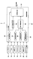
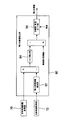
- FIG. 1 is a block diagram showing the vehicle control system of the first embodiment.
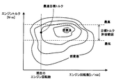
- FIG. 2 is a characteristic diagram showing the relationship between the engine speed and the fuel consumption in the allowable torque range.
- FIG. 3 is a characteristic diagram illustrating the synthesis of the first target value and the second target value.
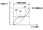
- FIG. 4 is a characteristic diagram showing the relationship among the first target value, the second target value, and the third target value.
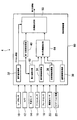
- FIG. 5 is a block diagram showing the vehicle control system of the second embodiment.
- FIG. 6 is a characteristic diagram illustrating the synthesis of the first target value and the second target value.
- FIG. 7 is a block diagram illustrating a second target value setting unit of the third embodiment.
- FIG. 8 is a block diagram illustrating a second target value setting unit of the fourth embodiment.
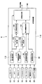
- FIG. 9 is a block diagram showing the vehicle control system of the fifth embodiment.
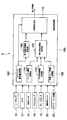
- FIG. 10 is a block diagram showing the vehicle control system of the sixth embodiment.
- a vehicle control system 2 shown in FIG. 1 is mounted on a vehicle and controls vehicle travel.
- the vehicle control system 2 includes various sensors for detecting the amount of driving operation of the driver, the traveling state of the host vehicle, the traveling state of the front vehicle traveling in front of the host vehicle, the road state where the host vehicle is traveling, and the like. It is mainly comprised from the apparatus and the vehicle control apparatus 30.
- FIG. 1 A vehicle control system 2 shown in FIG. 1 is mounted on a vehicle and controls vehicle travel.
- the vehicle control system 2 includes various sensors for detecting the amount of driving operation of the driver, the traveling state of the host vehicle, the traveling state of the front vehicle traveling in front of the host vehicle, the road state where the host vehicle is traveling, and the like. It is mainly comprised from the apparatus and the vehicle control apparatus 30.
- the vehicle control system 2 includes a radar sensor 10, a camera 12, a vehicle speed sensor 14, an accelerator sensor 16, a brake sensor 18, a steering angle sensor 20, a navigation device 22 and the like as various sensors and various devices.
- the radar sensor 10 scans and outputs laser light within a predetermined angle range to the front, side, and rear of the host vehicle, detects the reflected light, and the laser light is between the object that reflected the laser light.
- the distance from the time required to reciprocate to the object and the direction in which the object exists are determined from the direction in which the laser beam is irradiated when the reflected light is detected.
- the radar sensor 10 is not limited to the one that uses laser light, but may use one that uses radio waves in the millimeter wave band or microwave band, or one that uses ultrasonic waves.
- the camera 12 images the front, side, and rear of the vehicle.
- Image data captured by the camera 12 is analyzed by an image analysis device (not shown), and it is detected whether an object existing in front, side, and rear of the host vehicle is a vehicle or an obstacle.
- the vehicle speed sensor 14 detects the current vehicle speed of the host vehicle, and the accelerator sensor 16 detects the amount of depression of the accelerator pedal.
- the brake sensor 18 detects the depression amount of the brake pedal, and the steering angle sensor 20 detects the steering angle of the steering.
- the navigation device 22 includes GPS and map data.
- the navigation device 22 measures the position of the host vehicle based on the GPS signal received from the GPS satellite, maps the position of the host vehicle on the map data, and guides the travel route of the host vehicle.
- the vehicle control device 30 communicates with other ECUs via a microcomputer including a CPU, ROM, RAM, flash memory, an A / D conversion circuit, an input / output interface (I / O), and an in-vehicle LAN. It has a circuit.
- the operation amount acquisition unit 32, the vehicle information acquisition unit 34, the front vehicle information acquisition unit 36, the road information acquisition unit 38, and the first target value setting unit are realized by software such as microcomputer hardware and a control program. 40, a second target value setting unit 42, and a target value synthesizing unit 50.
- the operation amount acquisition unit 32 acquires the depression amount of the accelerator pedal from the accelerator sensor 16 as the driving operation amount of the driver, acquires the depression amount of the brake pedal from the brake sensor 18, and the steering angle of the steering from the steering angle sensor 20. Etc.
- the operation amount acquisition unit 32 calculates the steering speed of the steering by the driver from the amount of change in the steering angle of the steering.
- the vehicle information acquisition unit 34 acquires the engine speed, the host vehicle speed, the generator speed, and the like as the travel information of the host vehicle. Furthermore, the vehicle information acquisition unit 34 acquires an optimal target torque from the map shown in FIG. 2 so that the fuel consumption is optimal within the range of engine torque that is allowable for the current engine speed.
- the front vehicle information acquisition unit 36 detects from the radar sensor 10, the camera 12, and the like that there is a forward vehicle traveling in front of the host vehicle, and uses the inter-vehicle distance between the front vehicle and the host vehicle as travel information of the preceding vehicle. The vehicle speed of the vehicle ahead is acquired.
- the road information acquisition unit 38 acquires, as road information, the gradient of the road ahead of which the host vehicle is traveling, the degree of the curve, and the like from the map DB provided in the navigation device 22.
- the first target value setting unit 40 sets the target torque requested by the driver performing a driving operation based on the driving operation amount of the driver acquired by the operation amount acquiring unit 32 when the traveling of the host vehicle is controlled.
- One target value is set from a map or the like.
- the first target value setting unit 40 is a target torque requested by the driver operating the accelerator pedal based on the accelerator opening that is the amount of depression of the accelerator pedal acquired by the operation amount acquiring unit 32. Is set as the first target value for controlling the traveling of the host vehicle.
- the second target value setting unit 42 includes the travel information of the host vehicle acquired by the vehicle information acquisition unit 34, the travel information of the preceding vehicle acquired by the front vehicle information acquisition unit 36, and the host vehicle acquired by the road information acquisition unit 38. Based on the road information in front of the vehicle, an optimal target torque when the vehicle travel is controlled by automatic control is set as a second target value from a map or the like so as to improve the fuel consumption as much as possible.
- the target value synthesizing unit 50 synthesizes the first target value set by the first target value setting unit 40 and the second target value set by the second target value setting unit 42 to control the traveling of the host vehicle. Is set as the third target value.
- the target value synthesis unit 50 synthesizes the first target value and the second target value and sets the third target value if the accelerator opening is less than the predetermined opening as a predetermined threshold. To do.
- the target value synthesis unit 50 determines that the driver strongly desires to accelerate the host vehicle, and uses the second target value set by automatic control.
- the first target value set based on the driver's accelerator operation amount is set as the third target value.
- an engine control device (not shown) is configured as an electric drive source such as a throttle opening for a gasoline engine and a fuel injection amount of a fuel injection valve for a diesel engine. If a motor is provided, the amount of current supplied to the electric motor is controlled. Thereby, the output torque of the engine is controlled to the third target value.
- the target value synthesizing unit 50 sets the third target value by synthesizing the first target value and the second target value with the predetermined opening of the accelerator opening as a boundary, and sets the first target value to the third target.
- the third target value is set so that the third target value matches before and after switching at the predetermined opening.
- the first target value and the second target value are synthesized so that the third target value approaches the first target value as the accelerator opening increases and approaches the predetermined opening.
- the target value synthesis unit 50 changes the third target value within a range in which the driver feels that the traveling state of the host vehicle does not change before and after the switching of the third target value at the predetermined opening. May be.
- the target value composition unit 50 composes the first target value 200 and the second target value 202 to set the third target value 210
- the first target value 200 and the second target value 200 are combined.
- the third target value 210 is set so as to be between the target value 202.
- the first target value or the second target value is set as the third target value 210.
- the target value synthesizing unit 50 synthesizes the first target value 200 and the second target value 202 to set the third target value 210, and the first target value 200 and the second target value 202 are within the accelerator opening range.
- the third target value 210 is set from the following equations (1) and (2) so as to be between:
- Third target value second target value ⁇ (second target value ⁇ first target value) * f1 ⁇ (second target value ⁇ first target value) / second target value ⁇ (1)
- Third target value second target value + (first target value ⁇ second target value) * f2 ⁇ (first target value ⁇ second target value) / (first target value maximum value ⁇ second target value) ⁇ ...
- the first target value maximum value is the first target value within the accelerator opening range where the first target value 200 and the second target value 202 are combined to set the third target value 210. Is the maximum value.
- the target value synthesis unit 50 synthesizes the first target value and the second target value to set the third target value. On the other hand, if the accelerator opening is equal to or greater than the predetermined opening, the target value synthesis unit 50 sets the first target value as the third target value without using the second target value.
- the target value synthesizing unit 50 synthesizes the first target value and the second target value to set the third target value.
- the third target value appropriate for controlling the vehicle travel can be set by reflecting the amount of operation of the accelerator pedal by the driver while receiving.
- the target value synthesis unit 50 sets the first target value as the third target value without using the second target value.
- the increase / decrease direction of the difference between the second target value and the first target value, the second target value, the increase / decrease direction of the difference with the third target value matches. That is, the magnitude relationship between the second target value set based on the automatic control and the first target value set based on the driving operation amount of the driver is compared with the second target value set based on the automatic control and the actual value. This can be reflected in the magnitude relationship with the third target value when the vehicle travel is controlled.
- the magnitude relationship between the second target value set based on the automatic control and the first target value set based on the driving operation amount of the driver can be appropriately reflected in the third target value.
- the target value synthesis unit 50 sets the third target value so that the third target value matches before and after switching at the predetermined opening degree.
- the target value requested by the driver for the vehicle travel control by the driving operation matches the target value requested by the automatic control for the vehicle travel control. It is.
- the driver's request for vehicle travel control and the vehicle for automatic control can be obtained.
- the request for the travel control can be appropriately reflected in the vehicle travel control actually executed by the vehicle control device 30.
- the second target value is set so as to improve the fuel consumption as much as possible, and the second target value and the first target are combined to set the third target value when actually controlling the vehicle travel, Fuel consumption can be improved while reflecting the amount of driving operation of the driver.
- the vehicle control system 4 of the second embodiment shown in FIG. 5 differs from the vehicle control system 2 of the first embodiment in that a maximum value is set as the second target value.
- the other configuration of the vehicle control system 4 is substantially the same as that of the vehicle control system 2.
- the maximum value setting unit 62 sets the maximum value of the second target value when the automatic control controls the vehicle travel according to the accelerator opening by the driving operation of the driver. For example, the maximum value of the second target value is increased as the accelerator opening increases.
- the second target value setting unit 64 acquires the travel information of the host vehicle acquired by the vehicle information acquisition unit 34, the travel information of the preceding vehicle acquired by the front vehicle information acquisition unit 36, and the road information acquisition.
- the maximum value is output as the second target value.
- the second target value setting unit 64 outputs the second target value as it is to the target value synthesis unit 50 when the second target value is equal to or less than the maximum value.
- the target value synthesizing unit 50 synthesizes the first target value and the second target value to set the third target value if the accelerator opening is less than the predetermined opening. If the opening is equal to or greater than the predetermined opening, the first target value is set as the third target value without using the second target value.
- the second target value setting unit 64 When the second target value exceeds the maximum value, the second target value setting unit 64 outputs the maximum value as the second target value. Accordingly, although automatic control support for vehicle travel control is received, it is possible to prevent the automatic control support from becoming too large, and to appropriately reflect the request for vehicle travel according to the driving operation amount of the driver.
- the second target value setting unit 80 of the third embodiment shown in FIG. 7 is a torque value by automatic control so that the target inter-vehicle distance is set based on the traveling state of the host vehicle and the preceding vehicle. Set the target value.
- Other configurations of the vehicle control device of the third embodiment are substantially the same as those of the vehicle control device 30 of the first embodiment.
- the front vehicle-to-vehicle distance acquisition unit 70 acquires the inter-vehicle distance between the host vehicle and the front vehicle when there is a front vehicle traveling in front of the host vehicle based on the output of the radar sensor 10 or the camera 12.
- the host vehicle speed acquisition unit 72 acquires the host vehicle speed that is the speed of the host vehicle based on the output of the vehicle speed sensor 14.
- the second target value setting unit 80 includes a minimum inter-vehicle distance calculation unit 82, a torque calculation unit 84, and a target value / vehicle speed guard unit 86.
- the minimum inter-vehicle distance calculation unit 82 calculates the minimum inter-vehicle distance necessary for avoiding a collision with the preceding vehicle based on the own vehicle speed acquired from the own vehicle speed acquisition unit 72. In order to avoid a collision between the host vehicle and the preceding vehicle, the minimum inter-vehicle distance calculation unit 82 sets the minimum inter-vehicle distance longer as the host vehicle speed increases.
- the minimum inter-vehicle distance calculation unit 82 may set the minimum inter-vehicle distance based on the relative speed of the host vehicle with respect to the preceding vehicle. In this case, the minimum inter-vehicle distance calculation unit 82 sets the minimum inter-vehicle distance longer as the relative speed of the own vehicle with respect to the preceding vehicle increases and the speed at which the own vehicle approaches the preceding vehicle increases.
- the torque calculation unit 84 sets the difference inter-vehicle distance calculated by subtracting the minimum inter-vehicle distance calculated by the minimum inter-vehicle distance calculation unit 82 from the actual inter-vehicle distance between the host vehicle and the preceding vehicle as a margin for the inter-vehicle distance. Then, for example, the torque calculation unit 84 multiplies the difference inter-vehicle distance by a predetermined coefficient K, and calculates a torque value to be subtracted from the second target value previously calculated at the subsequent stage of the torque calculation unit 84.
- the coefficient K is set to a negative value.
- the previous second target value may be increased so that the differential inter-vehicle distance is shortened. Therefore, when the differential inter-vehicle distance is multiplied by a coefficient K, the torque calculated by the torque calculation unit 84 Becomes negative. And the absolute value of the negative torque which the torque calculation part 84 calculates becomes large, so that the difference inter-vehicle distance becomes long.
- the torque calculation unit 84 calculates. Torque is positive. And the absolute value of the positive torque which the torque calculation part 84 calculates becomes large, so that the negative absolute value of the difference inter-vehicle distance becomes large.
- the torque calculation unit 84 calculates the value of the torque to be subtracted from the previous second target value in the subsequent stage of the torque calculation unit 84 based on the difference inter-vehicle distance instead of multiplying the difference inter-vehicle distance by the coefficient K. May be.
- the target value / vehicle speed guard unit 86 sets the second target value as the torque guard value when the torque obtained by subtracting the torque calculated by the torque calculation unit 84 from the torque represented by the previous second target value becomes equal to or greater than the torque guard value. .
- the second target value is set to a negative value so that the host vehicle speed decreases when the current host vehicle speed exceeds the vehicle speed guard value set by the speed limit or the like.
- the negative absolute value of the second target value is increased as the speed difference obtained by subtracting the vehicle speed guard value from the host vehicle speed increases.
- the second target value can be set so that the host vehicle and the preceding vehicle have an appropriate inter-vehicle distance.
- the second target value setting unit 100 of the fourth embodiment shown in FIG. 8 sets the second target value so that the own vehicle, the front vehicle, and the rear vehicle have an appropriate inter-vehicle distance.
- Other configurations of the vehicle control device of the fourth embodiment are substantially the same as those of the vehicle control device 30 of the first embodiment.
- the surrounding vehicle information acquisition unit 90 of the third embodiment shown in FIG. 8 is based on the output of the radar sensor 10 or the camera 12, and the actual front inter-vehicle distance that is the actual inter-vehicle distance between the own vehicle and the preceding vehicle, and the own vehicle. And the actual rear inter-vehicle distance, which is the actual inter-vehicle distance between the vehicle and the rear vehicle.
- the second target value setting unit 100 includes a front-rear inter-vehicle distance calculation unit 102 and a target value / vehicle speed guard unit 86 having substantially the same configuration as that of the third embodiment.
- the front-rear inter-vehicle distance calculation unit 102 acquires the actual front inter-vehicle distance and the actual rear inter-vehicle distance acquired by the surrounding vehicle information acquisition unit 90, the road gradient in front of the host vehicle acquired by the road information acquisition unit 38, and the host vehicle speed acquisition. Based on the host vehicle speed acquired by the unit 72, the optimal inter-vehicle distance between the host vehicle, the front vehicle, and the rear vehicle is calculated.
- the front-rear vehicle distance calculation unit 102 calculates the minimum front inter-vehicle distance with the front vehicle and the minimum rear inter-vehicle distance with the rear vehicle based on the host vehicle speed acquired by the host vehicle speed acquisition unit 72.
- the front-rear inter-vehicle distance calculation unit 102 sets the front minimum inter-vehicle distance longer as the host vehicle speed increases in order to avoid a collision between the host vehicle and the preceding vehicle.
- the front-rear inter-vehicle distance calculation unit 102 sets the minimum rear inter-vehicle distance longer as the host vehicle speed decreases in order to avoid a collision between the host vehicle and the rear vehicle.
- the front-rear inter-vehicle distance calculation unit 102 shortens the minimum front inter-vehicle distance and the minimum rear inter-vehicle distance, If the road ahead of the vehicle is a downhill, the front minimum inter-vehicle distance and the rear minimum inter-vehicle distance are increased.
- the front-rear inter-vehicle distance calculation unit 102 calculates a front differential inter-vehicle distance as a difference between the actual forward inter-vehicle distance and the forward minimum inter-vehicle distance, and calculates a backward differential inter-vehicle distance as a difference between the actual rear inter-vehicle distance and the rear minimum inter-vehicle distance.
- the front-rear inter-vehicle distance calculation unit 102 equalizes the margin of the inter-vehicle distance between the host vehicle, the front vehicle, and the rear vehicle by calculating an average value of the front difference vehicle distance and the rear difference vehicle distance.
- the front-rear inter-vehicle distance calculation unit 102 adds the average value of the calculated forward differential inter-vehicle distance and rear differential inter-vehicle distance to the minimum front inter-vehicle distance and the minimum rear inter-vehicle distance, respectively, and calculates the optimum front inter-vehicle distance and the optimal rear inter-vehicle distance. calculate.
- the inter-vehicle distance between the host vehicle, the front vehicle and the rear vehicle is set to the optimal inter-vehicle distance. Can do.
- the torque calculation unit 84 follows the difference in the front vehicle distance between the actual front inter-vehicle distance and the optimum front inter-vehicle distance or the rear inter-vehicle distance difference between the actual rear inter-vehicle distance and the optimum rear inter-vehicle distance.
- the torque value to be subtracted from the previous second target value is calculated from a map or the like.
- the previous second target value may be increased so that the front inter-vehicle distance difference is shorter than the current one. Therefore, the torque calculated by the torque calculation unit 84 is negative. Value. And the absolute value of the negative torque which the torque calculation part 84 calculates becomes large, so that the front inter-vehicle distance difference becomes long.
- the torque calculated by the torque calculation unit 84 is positive. Value. And the absolute value of the positive torque which the torque calculation part 84 calculates becomes large, so that the negative absolute value of the front inter-vehicle distance difference becomes large.
- the target value / vehicle speed guard unit 86 when the torque obtained by subtracting the torque calculated by the torque calculation unit 84 from the torque represented by the previous second target value becomes equal to or greater than the torque guard value. Set the value to the torque guard value. Further, the second target value is set to a negative value so that the host vehicle speed decreases if the current vehicle speed of the host vehicle exceeds a vehicle speed guard value set by a speed limit or the like.
- the second target value is set so that the own vehicle, the front vehicle, and the rear vehicle have an appropriate inter-vehicle distance. Can be set.
- the vehicle control device 110 sets the brake torque as the first target value based on the depression amount of the brake pedal as the driving operation amount of the driver. Further, the regenerative torque generated by the generator driven by the engine rotation is set as the second target value.
- the vehicle control device 110 is different from the first embodiment in that the first target value and the second target value are combined and a third target value that acts as a braking force for the engine output torque is set.
- the vehicle control device 110 includes a front vehicle information acquisition unit 36, a road information acquisition unit 38, a brake pedal operation amount acquisition unit 112, a generator rotation speed acquisition unit 114, a brake torque calculation unit 120, and a maximum regenerative torque calculation.
- the brake pedal operation amount acquisition unit 112 acquires the depression amount of the brake pedal from the brake sensor 18.
- the generator rotational speed acquisition unit 114 acquires the rotational speed of the on-vehicle generator from a rotational speed sensor installed in the generator or an engine rotational speed.
- the brake torque calculation unit 120 calculates the brake torque based on the brake pedal depression amount acquired by the brake pedal operation amount acquisition unit 112.
- the maximum regenerative torque calculation unit 122 calculates the maximum value of the regenerative torque that is generated when the generator generates electric power, based on the rotation speed of the generator acquired by the generator rotation speed acquisition unit 114.
- the first target value setting unit 130 sets the brake torque calculated by the brake torque calculation unit 120 as the first target value.
- the second target value setting unit 132 includes a maximum generator regenerative torque calculated by the maximum regenerative torque calculation unit 122, a distance between the front vehicle and the host vehicle acquired by the front vehicle information acquisition unit 36, and a road information acquisition unit.
- the regenerative torque is set as a second target value for automatic control based on the slope of the road ahead, the degree of curve, and the like on which the host vehicle acquired by the vehicle 38 is traveling.
- the target value synthesizing unit 140 synthesizes the first target value set by the first target value setting unit 130 and the second target value set by the second target value setting unit 132 to the engine output torque of the host vehicle.
- a third target value is set as the target value of the braking force.
- the target value synthesis unit 140 synthesizes the first target value and the second target to obtain the third target value. Set.
- the target value composition unit 140 determines that the driver has depressed the brake pedal greatly in order to avoid collision with an object ahead, and uses the second target value. First, the first target value is set as the third target value.
- the target value synthesis unit 140 synthesizes the first target value and the second target value to set the third target value.
- the target value composition unit 140 sets the first target value as the third target value without using the second target value.
- the target value composition unit 140 synthesizes the first target value and the second target value to set the third target value. It is possible to set an appropriate third target value for controlling the vehicle traveling by reflecting the depression amount of the brake pedal by the driver while receiving the traveling support.
- the target value composition unit 140 sets the first target value as the third target value without using the second target value.
- the vehicle control system 8 of the sixth embodiment shown in FIG. 10 is different from the first embodiment in that the vehicle control device 150 sets the steering amount of the wheel as the first target value, the second target value, and the third target value. Is different.
- the vehicle control device 150 includes a steering operation amount acquisition unit 152, a blinker information acquisition unit 154, a parallel vehicle information acquisition unit 156, a lane / curve information acquisition unit 158, a first target value setting unit 160, and a second target value.
- a setting unit 162 and a target value synthesis unit 170 are provided.
- the steering operation amount acquisition unit 152 acquires the steering angle and steering speed of the steering from the steering angle sensor 20.
- the winker information acquisition unit 154 acquires whether the winker indicates the right direction or the left direction.
- the parallel vehicle information acquisition unit 156 uses the radar sensor 10 and the camera as the parallel vehicle information traveling in the lane adjacent to the lane in which the host vehicle is traveling, such as the presence / absence of the parallel vehicle, the distance between the host vehicle and the vehicle speed. 12 from.
- the lane / curve information acquisition unit 158 acquires from the navigation device 22 information on the lane of the road on which the host vehicle is traveling and how much the road is curved.
- the first target value setting unit 160 sets the steering amount and the steering speed for the wheel as the first target value based on the steering angle and steering speed of the steering acquired by the steering operation amount acquisition unit 152.
- the second target value setting unit 162 steers the wheels as automatic control based on the above-described direction direction of the blinker, information on parallel vehicles traveling in the adjacent lane, and road information on which the host vehicle is traveling. The amount and the steering speed are set as the second target value.
- the second target value setting unit 162 The wheel steering speed is set faster than when the vehicle is not traveling in the lane.
- the target value composition unit 170 sets the first target value as the first target value.
- the third target value output by combining the second target value is faster than the steering speed indicated by the first target value set by the driver steering the steering.
- the host vehicle can be moved to the right lane before another vehicle traveling in the right lane of the host vehicle gets too close to the host vehicle.
- the second target value setting unit 162 is configured such that when the turn signal direction is on the right side, the turn signal direction direction is on the left side.
- a second target value that is a target value of the steering amount for the wheel is set large.
- the second target value setting unit 162 determines that the direction of the turn signal is on the left side and the direction of the turn signal is on the right side.
- the second target value that is the target value of the steering amount for the wheel is set to be large.
- the second target value setting unit 162 can set the second target value according to the degree of the curve of the road and the lane changing direction.
- the target value synthesis unit 170 synthesizes the first target value and the second target value when the steering angle or steering speed of the driver acquired by the steering operation amount acquisition unit 152 is less than a predetermined threshold set accordingly. Then, the steering amount and the steering speed for the wheel are set as the third target value.
- the target value synthesis unit 170 is large in order for the driver to avoid an object ahead, Alternatively, it is determined that the steering is operated quickly, and the first target value is set as the third target value without using the second target value.
- the target value synthesis unit 170 synthesizes the first target value and the second target value to generate the third target value. Set.
- the target value composition unit 170 uses the first target value as the third target value without using the second target value.
- the target value synthesis unit 170 synthesizes the first target value and the second target value to generate the third target. Since the value is set, it is possible to set an appropriate third target value for controlling the vehicle travel while reflecting the steering operation amount by the driver while receiving the travel support by the automatic control.
- the target value composition unit 170 uses the first target value as the third target value without using the second target value. Set as. Thereby, when the control request
- the driver's driving operation amount for example, when the accelerator opening, the brake pedal depression amount, and the steering operation amount are equal to or greater than a predetermined threshold set for each driving operation amount, The first target value was set as the third target value without using the second target value.
- the first target value set based on the driving operation amount is equal to or greater than a predetermined threshold value
- the first target value may be set as the third target value without using the second target value.
- the second target value setting unit 64 may output 0 as the second target value.
- the maximum value setting unit 62 may not be installed, and the target value synthesis unit 50 may set the maximum value of the second target value. Then, the target value synthesis unit 50 may determine whether or not the second target value exceeds the maximum value.
- the functions of one component in the above embodiment may be distributed as a plurality of components, or the functions of a plurality of components may be integrated into one component. Further, at least a part of the configuration of the above embodiment may be replaced with another configuration having the same function. Moreover, you may abbreviate
- a vehicle control system including the vehicle control device as a constituent element, a program for causing a computer to function as the vehicle control device, a recording medium recording the program, a vehicle control method, etc.
- Various forms can also be used as embodiments.
- the operation amount acquisition unit corresponds to an operation amount acquisition unit.
- the first target value setting units 40, 130, and 160 correspond to a first setting unit and a first setting unit.
- the second target value setting units 42, 64, 80, 100, 132, 162 correspond to a second setting unit and a second setting unit.
- the target value combining units 50, 140, and 170 correspond to a third setting unit and a third setting unit.
- the maximum value setting unit 62 corresponds to maximum value setting means.
- the brake pedal operation amount acquisition unit 112 corresponds to an operation amount acquisition unit and an operation amount acquisition unit.
- the steering operation amount acquisition unit 152 corresponds to an operation amount acquisition unit and an operation amount acquisition unit.
Abstract
操作量取得部(32)と、第1設定部(40)と、第2設定部(42)と、第3設定部(50)と、を備える車両制御装置を提供する。操作量取得部(32)はドライバの運転操作量を取得する。第1設定部(40)は、操作量取得部(32)が取得する運転操作量に基づいて、車両走行を制御するときの第1目標値を設定する。第2設定部(42)は、自動制御により車両走行を制御するときの第2目標値を設定する。第3設定部(50)は、運転操作量または第1目標値に基づいて第1目標値と第2目標値とを合成し、車両走行を実際に制御するときの第3目標値を設定する。
Description
本出願は、2015年2月20日に出願された日本国特許出願2015-31742号に基づくものであり、その開示をここに参照により援用する。
本開示は、ドライバの運転操作と自動制御とに基づいて車両走行を制御する技術に関する。
車を運転するドライバの操作負担を軽減する技術の一つとして、例えば、自車両の前方を走行する前方車両と自車両との車間距離を一定に保持するように自車車速等を自動制御して前方車両に追従させる車両制御装置が知られている(例えば、特許文献1参照。)。
従来の車両制御装置においては、アクセルペダル、ブレーキペダル等に対するドライバの運転操作に基づいて車両走行を制御するか、あるいは自動制御で車両走行を制御するかは、ドライバが自動制御による走行支援スイッチをオフにするかオンにするかで切り替えられる。また、自動制御中においてドライバがアクセルペダル等を操作して自分で車両走行を制御する意志を示すと、自動制御は中止される。
前述したように、従来の技術では、ドライバの運転操作または車両制御装置による自動制御のいずれか一方で車両走行が制御される。したがって、ドライバが自分で運転操作をして車両走行を制御したい状況と、ドライバが自動制御に車両制御を任せたい状況とが頻繁に切り替わる場合、ドライバはその都度走行支援スイッチを操作しなければならない。このような操作は煩雑である。
本開示の目的の一つは、上記を鑑みて、ドライバの運転操作と自動制御とに基づいて適切に車両走行を制御する技術を提供することにある。
本開示の一側面の車両制御装置は、操作量取得部と、第1設定部と、第2設定部と、第3設定部と、を備えている。
操作量取得部はドライバの運転操作量を取得する。第1設定部は、操作量取得部が取得する運転操作量に基づいて、車両走行を制御するときの第1目標値を設定する。第2設定部は、自動制御により車両走行を制御するときの第2目標値を設定する。第3設定部は、運転操作量または第1目標値に基づいて第1目標値と第2目標値とを合成し、車両走行を実際に制御するときの第3目標値を設定する。
この構成によれば、ドライバの運転操作量に基づいて設定される第1目標値と自動制御により設定される第2目標値とを車両制御装置が合成して車両走行を実際に制御するときの第3目標値を設定する。したがって、ドライバがスイッチ等を操作して、ドライバの運転操作による車両制御と自動制御による車両制御とを切り替える必要がない。
さらに、自動制御による走行支援を受けつつドライバによる運転操作量を反映して、車両走行を制御するときの適切な第3目標値を設定できる。
また、運転操作量または運転操作量に基づいて設定される第1目標値に基づいて第1目標値と第2目標値とを合成するので、ドライバの運転操作量を適切に反映して、車両走行を実際に制御するときの第3目標値を設定できる。
本開示についての上記および他の目的、特徴、利点は、添付図面を参照した下記詳細な説明から、より明確になる。図面において、
図1は、第1実施形態の車両制御システムを示すブロック図である。
図2は、エンジン回転数と許容トルク範囲における燃費との関係を示す特性図である。
図3は、第1目標値と第2目標値との合成を説明する特性図である。
図4は、第1目標値と第2目標値と第3目標値との関係を示す特性図である。
図5は、第2実施形態の車両制御システムを示すブロック図である。
図6は、第1目標値と第2目標値との合成を説明する特性図である。
図7は、第3実施形態の第2目標値設定部を示すブロック図である。
図8は、第4実施形態の第2目標値設定部を示すブロック図である。
図9は、第5実施形態の車両制御システムを示すブロック図である。
図10は、第6実施形態の車両制御システムを示すブロック図である。
以下、実施形態を図に基づいて説明する。
[1.第1実施形態]
[1-1.構成]
図1に示す車両制御システム2は、車両に搭載され、車両走行を制御するものである。車両制御システム2は、ドライバの運転操作量、自車両の走行状態、自車両の前方を走行する前方車両の走行状態、自車両が走行している道路状態等を検出するための各種センサおよび各種装置と、車両制御装置30とから主に構成されている。
[1-1.構成]
図1に示す車両制御システム2は、車両に搭載され、車両走行を制御するものである。車両制御システム2は、ドライバの運転操作量、自車両の走行状態、自車両の前方を走行する前方車両の走行状態、自車両が走行している道路状態等を検出するための各種センサおよび各種装置と、車両制御装置30とから主に構成されている。
車両制御システム2は、各種センサおよび各種装置として、レーダセンサ10、カメラ12、車速センサ14、アクセルセンサ16、ブレーキセンサ18、操舵角センサ20、ナビゲーション装置22などを備えている。
レーダセンサ10は、自車両の前方と側方と後方とへレーザ光を所定角度の範囲でスキャンして出力してその反射光を検出し、レーザ光を反射した物体との間をレーザ光が往復するのに要した時間から物体までの距離と、反射光を検出した時にレーザ光を照射した方向から物体が存在する方位とを求める。尚、レーダセンサ10は、レーザ光を利用するものに限らず、ミリ波帯またはマイクロ波帯の電波を利用するものや、超音波を利用するものを使用してもよい。
カメラ12は自車両の前方と側方と後方とを撮像するものである。カメラ12が撮像した画像データは図示しない画像解析装置で解析され、自車両の前方と側方と後方とに存在する物体が車両であるか障害物であるかなどが検出される。
車速センサ14は自車両の現在車速を検出し、アクセルセンサ16はアクセルペダルの踏み込み量を検出する。ブレーキセンサ18はブレーキペダルの踏み込み量を検出し、操舵角センサ20はステアリングの操舵角を検出する。
ナビゲーション装置22はGPSと地図データとを備えている。ナビゲーション装置22は、GPS衛星から受信するGPS信号に基づいて自車両の位置を測位し、地図データ上に自車両の位置をマッピングするとともに、自車両の走行経路を案内する。
車両制御装置30は、CPU、ROM、RAM、フラッシュメモリなどを備えるマイクロコンピュータ、A/D変換回路、入出力インターフェース(I/O)、および車内LANを介して他のECUとの通信を行う通信回路などを備えている。
そして、マイクロコンピュータのハードウェアおよび制御プログラム等のソフトウェアにより、操作量取得部32と、車両情報取得部34と、前車情報取得部36と、道路情報取得部38と、第1目標値設定部40と、第2目標値設定部42と、目標値合成部50と、が構成されている。
操作量取得部32は、ドライバの運転操作量として、アクセルセンサ16からアクセルペダルの踏み込み量を取得し、ブレーキセンサ18からブレーキルペダルの踏み込み量を取得し、操舵角センサ20からステアリングの操舵角等を取得する。操作量取得部32は、ステアリングの操舵角の変化量からドライバによるステアリングの操舵速度を算出する。
車両情報取得部34は、自車両の走行情報として、エンジン回転数、自車車速、発電機の回転数等を取得する。さらに、車両情報取得部34は、図2に示すマップから、現在のエンジン回転数に対して許容できるエンジントルクの範囲内で燃費が最良になるように最適な目標トルクを取得する。
前車情報取得部36は、レーダセンサ10、カメラ12等から、自車両の前方を走行する前方車両が存在することを検出し、前方車両の走行情報として、前方車両と自車両との車間距離、前方車両の車速等を取得する。
道路情報取得部38は、道路情報として、ナビゲーション装置22が備える地図DBから、自車両が走行する前方の道路の勾配、カーブの度合等を取得する。
第1目標値設定部40は、操作量取得部32が取得するドライバの運転操作量に基づいて、ドライバが運転操作をすることにより要求する目標トルクを、自車両の走行を制御するときの第1目標値としてマップ等から設定する。
第1実施形態では、第1目標値設定部40は、操作量取得部32が取得するアクセルペダルの踏み込み量であるアクセル開度に基づいて、ドライバがアクセルペダルを操作することにより要求する目標トルクを、自車両の走行を制御するときの第1目標値として設定する。
第2目標値設定部42は、車両情報取得部34が取得する自車両の走行情報と、前車情報取得部36が取得する前方車両の走行情報と、道路情報取得部38が取得する自車両の前方の道路情報とに基づいて、燃費ができるだけ向上するように、自動制御で車両走行を制御するときの最適な目標トルクを、第2目標値としてマップ等から設定する。
目標値合成部50は、第1目標値設定部40が設定した第1目標値と、第2目標値設定部42が設定した第2目標値とを合成して、自車両の走行を制御するときの実際の目標トルクを第3目標値として設定する。
図3に示すように、目標値合成部50は、アクセル開度が所定の閾値として所定開度未満であれば、第1目標値と第2目標値とを合成して第3目標値を設定する。
一方、アクセル開度が所定開度以上であれば、目標値合成部50は、ドライバが自車両を加速させることを強く望んでいると判断し、自動制御により設定される第2目標値を使用せずドライバのアクセル操作量に基づいて設定される第1目標値を第3目標値として設定する。
図示しないエンジン制御装置は、目標値合成部50が出力する第3目標値に基づいて、ガソリンエンジンであればスロットル開度、ディーゼルエンジンであれば燃料噴射弁の燃料噴射量等、駆動源として電気モータを備えるものであれば電気モータへの通電量を制御する。これにより、エンジンの出力トルクは第3目標値に制御される。
目標値合成部50は、アクセル開度の所定開度を境界として、第1目標値と第2目標値とを合成して第3目標値を設定するときと、第1目標値を第3目標値として設定するときとが切り替わる場合、所定開度において切り替わる前後で第3目標値が一致するように第3目標値を設定する。例えば、アクセル開度が上昇して所定開度に近づくにしたがい、第3目標値が第1目標値に近づくように、第1目標値と第2目標値とを合成する。
尚、目標値合成部50は、所定開度において第3目標値が切り替わる前後で、ドライバが自車両の走行状態が変化せず一致していると感じる範囲内で、第3目標値を変化させてもよい。
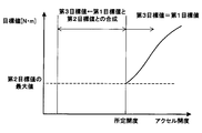
また、目標値合成部50は、図4に示すように、第1目標値200と第2目標値202とを合成して第3目標値210を設定する場合、第1目標値200と第2目標値202との間になるように第3目標値210を設定する。第1目標値200と第2目標値202とが等しい場合には、第3目標値210に第1目標値または第2目標値を設定する。
尚、図4においては、説明を簡単にするために、自動制御が車両走行を制御するときの第2目標値がアクセル開度によって変化しない例を示している。
目標値合成部50は、第1目標値200と第2目標値202とを合成して第3目標値210を設定するアクセル開度の範囲内において、第1目標値200と第2目標値202との間になるように、次式(1)、(2)から第3目標値210を設定する。
第1目標値<第2目標値の場合、次式(1)。
第3目標値=第2目標値-(第2目標値-第1目標値)*f1{(第2目標値-第1目標値)/第2目標値} ・・・(1)
式(1)において、f1(0)=0、f1(1)=1、0≦x≦1でf1(x)は単調増加である。
式(1)において、f1(0)=0、f1(1)=1、0≦x≦1でf1(x)は単調増加である。
第1目標値≧第2目標値の場合、次式(2)。
第3目標値=第2目標値+(第1目標値-第2目標値)*f2{(第1目標値-第2目標値)/(第1目標値最大値-第2目標値)} ・・・(2)
式(2)において、f2(0)=0、f2(1)=1、0≦x≦1でf2(x)は単調増加である。
式(2)において、f2(0)=0、f2(1)=1、0≦x≦1でf2(x)は単調増加である。
式(2)において、第1目標値最大値は、第1目標値200と第2目標値202とを合成して第3目標値210を設定するアクセル開度の範囲内において、第1目標値の最大値である。
[1-2.効果]
以上説明した第1実施形態によれば、以下の効果が得られる。
以上説明した第1実施形態によれば、以下の効果が得られる。
(1)アクセル開度が所定開度未満であれば、目標値合成部50は、第1目標値と第2目標値とを合成して第3目標値を設定する。一方、アクセル開度が所定開度以上であれば、目標値合成部50は、第2目標値を使用せず第1目標値を第3目標値として設定する。
これにより、ドライバのアクセル操作による車両制御と自動制御による車両制御とを、ドライバがスイッチ等を操作して切り替える必要がない。
(2)アクセル開度が所定開度未満であれば、目標値合成部50は、第1目標値と第2目標値とを合成して第3目標値を設定するので、自動制御による走行支援を受けつつドライバによるアクセルペダルの操作量を反映して、車両走行を制御するときの適切な第3目標値を設定できる。
(3)アクセルペダルの操作量が所定開度以上であれば、目標値合成部50は、第2目標値を使用せず第1目標値を第3目標値として設定する。これにより、ドライバの車両走行に対する制御要求が大きくなると、ドライバの意志にしたがって車両走行を制御できる。
(4)式(1)、(2)から図4に示すように第3目標値を設定することにより、ドライバの運転操作量に基づいて設定される第1目標値の増減方向と、車両制御装置30が車両走行を実際に制御するときの第3目標値の増減方向とが一致する。これにより、ドライバが運転操作量で示す運転操作に対する意志を、車両制御装置30が実際に実行する車両走行制御に反映することができる。
(5)式(1)、(2)から図4に示すように第3目標値を設定することにより、第2目標値と第1目標値との差分の増減方向と、第2目標値と第3目標値との差分の増減方向とが一致する。つまり、自動制御に基づいて設定される第2目標値とドライバの運転操作量に基づいて設定される第1目標値との大小関係を、自動制御に基づいて設定される第2目標値と実際に車両走行を制御するときの第3目標値との大小関係に反映できる。
これにより、自動制御に基づいて設定される第2目標値とドライバの運転操作量に基づいて設定される第1目標値との大小関係を、第3目標値に適切に反映できる。
(6)アクセル開度の所定開度を境界に、第1目標値と第2目標値とを合成して第3目標値を設定するときと、第1目標値を第3目標値として設定するときとが切り替わる場合、目標値合成部50は、所定開度において切り替わりの前後で第3目標値が一致するように第3目標値を設定する。
これにより、所定開度を境界にして第3目標値が連続して変化する。その結果、所定開度を境界にしてアクセル開度が変化しても、車両走行に対する制御を滑らかに変化させることができる。
(7)第1目標値と第2目標値とが一致するときは、ドライバが運転操作により車両走行制御に要求する目標値と、自動制御が車両走行制御に要求する目標値とが一致するときである。
したがって、第1目標値と第2目標値とが一致するときに第3目標値を第1目標値または第2目標値と一致させることにより、ドライバの車両走行制御に対する要求と、自動制御の車両走行制御に対する要求とを、車両制御装置30が実際に実行する車両走行制御に適切に反映できる。
(8)燃費ができるだけ向上するように第2目標値を設定し、この第2目標値と第1目標とを合成して車両走行を実際に制御するときの第3目標値を設定するので、ドライバの運転操作量を反映しつつ燃費を向上できる。
[2.第2実施形態]
[2-1.構成]
図5に示す第2実施形態の車両制御システム4は、第2目標値に最大値を設定する点で第1実施形態の車両制御システム2と異なる。それ以外の車両制御システム4の構成は車両制御システム2と実質的に同一である。
[2-1.構成]
図5に示す第2実施形態の車両制御システム4は、第2目標値に最大値を設定する点で第1実施形態の車両制御システム2と異なる。それ以外の車両制御システム4の構成は車両制御システム2と実質的に同一である。
最大値設定部62は、ドライバの運転操作によるアクセル開度に応じて、自動制御が車両走行を制御するときの第2目標値の最大値を設定する。例えば、アクセル開度が大きくなるにしたがい第2目標値の最大値を大きくする。
図6に示すように、第2目標値設定部64は、車両情報取得部34が取得する自車両の走行情報と、前車情報取得部36が取得する前方車両の走行情報と、道路情報取得部38が取得する自車両の前方の道路情報とに基づいて設定する第2目標値がアクセル開度に基づいて設定した最大値を越える場合には、最大値を第2目標値として出力する。第2目標値設定部64は、第2目標値が最大値以下の場合、第2目標値をそのまま目標値合成部50に出力する。
目標値合成部50は、第1実施形態と同様に、アクセル開度が所定開度未満であれば、第1目標値と第2目標値とを合成して第3目標値を設定し、アクセル開度が所定開度以上であれば、第2目標値を使用せず第1目標値を第3目標値として設定する。
[2-2.効果]
以上説明した第2実施形態によると、第1実施形態の効果(1)~(8)に加え、以下の効果を得ることができる。
以上説明した第2実施形態によると、第1実施形態の効果(1)~(8)に加え、以下の効果を得ることができる。
第2目標値設定部64は、第2目標値が最大値を越えると、最大値を第2目標値として出力する。これにより、車両走行の制御に対する自動制御の支援を受けるものの、自動制御の支援が大きくなりすぎることを防止し、ドライバの運転操作量に応じた車両走行に対する要求を適切に反映できる。
[3.第3実施形態]
[3-1.構成]
図7に示す第3実施形態の第2目標値設定部80は、自車両と前方車両との走行状態に基づいて設定される目標車間距離になるように、自動制御によるトルク値である第2目標値を設定する。これ以外の第3実施形態の車両制御装置の構成は、第1実施形態の車両制御装置30と実質的に同一である。
[3-1.構成]
図7に示す第3実施形態の第2目標値設定部80は、自車両と前方車両との走行状態に基づいて設定される目標車間距離になるように、自動制御によるトルク値である第2目標値を設定する。これ以外の第3実施形態の車両制御装置の構成は、第1実施形態の車両制御装置30と実質的に同一である。
前車車間距離取得部70は、レーダセンサ10またはカメラ12の出力に基づいて、自車両の前方を走行する前方車両が存在する場合に自車両と前方車両との車間距離を取得する。自車車速取得部72は、車速センサ14の出力に基づいて自車両の車速である自車車速を取得する。
第2目標値設定部80は、最小車間距離算出部82と、トルク算出部84と、目標値・車速ガード部86とを備えている。
最小車間距離算出部82は、自車車速取得部72から取得する自車車速に基づいて、前方車両との衝突を回避するために必要な最小車間距離を算出する。自車両と前方車両との衝突を回避するため、最小車間距離算出部82は、自車車速が速くなるほど最小車間距離を長く設定する。
最小車間距離算出部82は、前方車両に対する自車両の相対速度に基づいて最小車間距離を設定してもよい。この場合、最小車間距離算出部82は、前方車両に対する自車両の相対速度が速くなり、自車両が前方車両に近づく速度が速くなるほど最小車間距離を長く設定する。
トルク算出部84は、自車両と前方車両との実際の車間距離から最小車間距離算出部82が算出する最小車間距離を減算して算出される差分車間距離を車間距離の余裕分とする。そして、例えば、トルク算出部84は、差分車間距離に所定の係数Kを乗じて、トルク算出部84の後段で前回算出した第2目標値から減算するトルクの値を算出する。係数Kは負の値に設定される。
例えば、差分車間距離が正の値であれば差分車間距離が短くなるように前回の第2目標値を増加してよいので、差分車間距離に係数Kを乗じるとトルク算出部84が算出するトルクは負の値になる。そして、差分車間距離が長くなるほど、トルク算出部84が算出する負のトルクの絶対値は大きくなる。
一方、差分車間距離が負の値であれば差分車間距離が長くなるように前回の第2目標値を低下させる必要があるので、差分車間距離に係数Kを乗じるとトルク算出部84が算出するトルクは正の値になる。そして、差分車間距離の負の絶対値が大きくなるほど、トルク算出部84が算出する正のトルクの絶対値は大きくなる。
尚、トルク算出部84は、差分車間距離に係数Kを乗じる代わりに、トルク算出部84の後段で前回の第2目標値から減算するトルクの値を、差分車間距離に基づいてマップ等から算出してもよい。
目標値・車速ガード部86は、前回の第2目標値が表わすトルクからトルク算出部84が算出するトルクを減算したトルクがトルクガード値以上になると、第2目標値をトルクガード値に設定する。
また、現在の自車車速が制限速度等で設定される車速ガード値を越えると、自車車速が低下するように、第2目標値を負の値に設定する。この場合、自車車速から車速ガード値を減算した速度差が大きくなるほど、第2目標値の負の絶対値を大きくする。
[3-2.効果]
以上説明した第3実施形態によると、第1実施形態の効果(1)~(3)に加え、自車両と前方車両とが適切な車間距離になるように第2目標値を設定できる。
以上説明した第3実施形態によると、第1実施形態の効果(1)~(3)に加え、自車両と前方車両とが適切な車間距離になるように第2目標値を設定できる。
[4.第4実施形態]
[4-1.構成]
図8に示す第4実施形態の第2目標値設定部100は、自車両と前方車両および後方車両とが適切な車間距離になるように第2目標値を設定する。これ以外の第4実施形態の車両制御装置の構成は、第1実施形態の車両制御装置30と実質的に同一である。
[4-1.構成]
図8に示す第4実施形態の第2目標値設定部100は、自車両と前方車両および後方車両とが適切な車間距離になるように第2目標値を設定する。これ以外の第4実施形態の車両制御装置の構成は、第1実施形態の車両制御装置30と実質的に同一である。
図8に示す第3実施形態の周辺車両情報取得部90は、レーダセンサ10またはカメラ12の出力に基づいて、自車両と前方車両との実際の車間距離である実前方車間距離、ならびに自車両と後方車両との実際の車間距離である実後方車間距離を取得する。
第2目標値設定部100は、前後車間距離算出部102と、第3実施形態と実質的に同一構成の目標値・車速ガード部86とを備えている。
前後車間距離算出部102は、周辺車両情報取得部90が取得する実前方車間距離および実後方車間距離と、道路情報取得部38が取得する自車両の前方の道路の勾配と、自車車速取得部72が取得する自車車速とに基づいて、自車両と前方車両および後方車両との最適な車間距離を算出する。
まず、前後車間距離算出部102は、自車車速取得部72が取得する自車車速に基づいて、前方車両との前方最小車間距離と、後方車両との後方最小車間距離とを算出する。
前後車間距離算出部102は、自車両と前方車両との衝突を回避するため、自車車速が速くなるほど前方最小車間距離を長く設定する。前後車間距離算出部102は、自車両と後方車両との衝突を回避するため、自車車速が遅くなるほど後方最小車間距離を長く設定する。
また、前後車間距離算出部102は、例えば、道路情報取得部38が取得する道路情報として自車両の前方の道路が上り坂であれば、前方最小車間距離および後方最小車間距離を短くし、自車両の前方の道路が下り坂であれば、前方最小車間距離および後方最小車間距離を長くする。
前後車間距離算出部102は、実前方車間距離と前方最小車間距離との差分として前方差分車間距離を算出し、実後方車間距離と後方最小車間距離との差分として後方差分車間距離を算出する。
そして、前後車間距離算出部102は、前方差分車間距離と後方差分車間距離との平均値を算出することにより、自車両と前方車両および後方車両との車間距離の余裕分を均等化する。前後車間距離算出部102は、算出した前方差分車間距離と後方差分車間距離との平均値を最小前方車間距離と最小後方車間距離とにそれぞれ加算し、最適前方車間距離と最適後方車間距離とを算出する。
実前方車間距離が最適前方車間距離になることにより、あるいは実後方車間距離が最適後方車間距離になることにより、自車両と前方車両および後方車両との車間距離を最適な車間距離に設定することができる。
そこで、トルク算出部84は、実前方車間距離と最適前方車間距離との前方車間距離差分、あるいは実後方車間距離と最適後方車間距離との後方車間距離差分に基づいて、トルク算出部84の後段で前回の第2目標値から減算するトルクの値をマップ等から算出する。
例えば、前方車間距離差分が正の値の場合、で前方車間距離差分が今よりも短くなるように前回の第2目標値を増加してよいので、トルク算出部84が算出するトルクは負の値になる。そして、前方車間距離差分が長くなるほど、トルク算出部84が算出する負のトルクの絶対値は大きくなる。
一方、前方車間距離差分が負の値の場合、前方車間距離差分が今よりも長くなるように前回の第2目標値を低下させる必要があるので、トルク算出部84が算出するトルクは正の値になる。そして、前方車間距離差分の負の絶対値が大きくなるほど、トルク算出部84が算出する正のトルクの絶対値は大きくなる。
目標値・車速ガード部86は、第3実施形態と同様に、前回の第2目標値が表わすトルクからトルク算出部84が算出するトルクを減算したトルクがトルクガード値以上になると、第2目標値をトルクガード値に設定する。また、現在の自車両の車速が制限速度等で設定される車速ガード値を越えると、自車車速が低下するように、第2目標値を負の値に設定する。
[4-2.効果]
以上説明した第4実施形態によると、第1実施形態の効果(1)~(3)に加え、自車両と前方車両および後方車両とが適切な車間距離になるように、第2目標値を設定できる。
以上説明した第4実施形態によると、第1実施形態の効果(1)~(3)に加え、自車両と前方車両および後方車両とが適切な車間距離になるように、第2目標値を設定できる。
[5.第5実施形態]
[5-1.構成]
図9に示す第5実施形態の車両制御システム6では、車両制御装置110は、ドライバの運転操作量としてブレーキペダルの踏み込み量に基づいて、ブレーキトルクを第1目標値として設定する。また、エンジンの回転によって駆動される発電機により発生する回生トルクを第2目標値として設定する。そして、車両制御装置110が、第1目標値と第2目標値とを合成し、エンジン出力トルクに対する制動力として作用する第3目標値を設定する点で第1実施形態と相違する。
[5-1.構成]
図9に示す第5実施形態の車両制御システム6では、車両制御装置110は、ドライバの運転操作量としてブレーキペダルの踏み込み量に基づいて、ブレーキトルクを第1目標値として設定する。また、エンジンの回転によって駆動される発電機により発生する回生トルクを第2目標値として設定する。そして、車両制御装置110が、第1目標値と第2目標値とを合成し、エンジン出力トルクに対する制動力として作用する第3目標値を設定する点で第1実施形態と相違する。
車両制御装置110は、前車情報取得部36と、道路情報取得部38と、ブレーキペダル操作量取得部112と、発電機回転数取得部114と、ブレーキトルク算出部120と、最大回生トルク算出部122と、第1目標値設定部130と、第2目標値設定部132と、目標値合成部140とを備えている。
ブレーキペダル操作量取得部112は、ブレーキセンサ18からブレーキペダルの踏み込み量を取得する。発電機回転数取得部114は、車載の発電機の回転数を、発電機に設置された回転数センサ、あるいはエンジン回転数から取得する。
ブレーキトルク算出部120は、ブレーキペダル操作量取得部112が取得するブレーキペダルの踏み込み量に基づいて、ブレーキトルクを算出する。最大回生トルク算出部122は、発電機回転数取得部114が取得する発電機の回転数に基づいて、発電機が電力を発生することにより生じる回生トルクの最大値を算出する。
第1目標値設定部130は、ブレーキトルク算出部120が算出するブレーキトルクを第1目標値として設定する。第2目標値設定部132は、最大回生トルク算出部122が算出する発電機の最大回生トルクと、前車情報取得部36が取得する前方車両と自車両との車間距離と、道路情報取得部38が取得する自車両が走行する前方の道路の勾配、カーブの度合等とに基づいて、自動制御の第2目標値としてとして回生トルクを設定する。
目標値合成部140は、第1目標値設定部130が設定する第1目標値と、第2目標値設定部132が設定する第2目標値とを合成して、自車両のエンジン出力トルクに対する制動力の目標値として第3目標値を設定する。
目標値合成部140は、ブレーキペダル操作量取得部112が取得するドライバのブレーキペダルの踏み込み量が所定の閾値未満の場合、第1目標値と第2目標とを合成して第3目標値を設定する。
目標値合成部140は、ブレーキペダルの踏み込み量が所定の閾値以上の場合、例えばドライバが前方の物体との衝突を避けるためにブレーキペダルを大きく踏み込んだと判断し、第2目標値を使用せず、第1目標値を第3目標値として設定する。
[5-2.効果]
以上説明した第5実施形態によると、以下の効果を得ることができる。
以上説明した第5実施形態によると、以下の効果を得ることができる。
(1)ブレーキペダルの踏み込み量が所定の閾値未満であれば、目標値合成部140は、第1目標値と第2目標値とを合成して第3目標値を設定する。一方、ブレーキペダルの踏み込み量が所定の閾値以上であれば、目標値合成部140は、第2目標値を使用せず第1目標値を第3目標値として設定する。
これにより、ドライバのブレーキ操作による車両制御と自動制御による車両制御とを、ドライバがスイッチ等を操作して切り替える必要がない。
(2)ブレーキペダルの踏み込み量が所定の閾値未満であれば、目標値合成部140は、第1目標値と第2目標値とを合成して第3目標値を設定するので、自動制御による走行支援を受けつつドライバによるブレーキペダルの踏み込み量を反映して、車両走行を制御するときの適切な第3目標値を設定できる。
例えば、回生トルクによる制動力を極力使用し、ブレーキペダル操作量に基づいて設定される機械式の油圧ブレーキによる制動力を極力低減して適切な制動力を設定できる。
(3)ブレーキペダルの踏み込み量が所定の閾値以上であれば、目標値合成部140は、第2目標値を使用せず第1目標値を第3目標値として設定する。これにより、ドライバの車両走行に対する制御要求が大きくなると、ドライバの意志にしたがって車両走行を制御できる。
[6.第6実施形態]
[6-1.構成]
図10に示す第6実施形態の車両制御システム8では、車両制御装置150が、第1目標値と第2目標値と第3目標値として車輪の操舵量を設定する点で第1実施形態と相違する。
[6-1.構成]
図10に示す第6実施形態の車両制御システム8では、車両制御装置150が、第1目標値と第2目標値と第3目標値として車輪の操舵量を設定する点で第1実施形態と相違する。
車両制御装置150はステアリング操作量取得部152と、ウィンカー情報取得部154と、平行車両情報取得部156と、車線・カーブ情報取得部158と、第1目標値設定部160と、第2目標値設定部162と、目標値合成部170とを備えている。
ステアリング操作量取得部152は、操舵角センサ20からステアリングの操舵角および操舵速度を取得する。ウィンカー情報取得部154は、ウィンカーが右方向または左方向のいずれを指示しているかを取得する。
平行車両情報取得部156は、自車両が走行している車線の隣車線を走行している平行車両情報として、平行車両の有無、自車両との車間距離、車速等を、レーダセンサ10およびカメラ12から取得する。車線・カーブ情報取得部158は、自車両が走行している道路の車線と、道路がどの程度カーブしているかの情報を、ナビゲーション装置22から取得する。
第1目標値設定部160は、ステアリング操作量取得部152が取得するステアリングの操舵角および操舵速度に基づいて、車輪に対する操舵量および操舵速度を第1目標値として設定する。
第2目標値設定部162は、前述したウィンカーの指示方向と、隣車線を走行している平行車両の情報と、自車両が走行している道路情報とに基づいて、自動制御として車輪に対する操舵量および操舵速度を第2目標値として設定する。
例えば、ウィンカーの指示方向が右側であり、自車両の右側車線の後方を他の車両が自車両との距離は十分離れているが走行している場合、第2目標値設定部162は、右側車線を車両が走行していない場合よりも車輪の操舵速度を速く設定する。
これにより、ドライバが右側の車線に進路を変更しようとしてステアリングを操舵する操舵速度が、右側車線を車両が走行していない場合と同じであっても、目標値合成部170が第1目標値と第2目標値とを合成して出力する第3目標値は、ドライバがステアリングを操舵することにより設定される第1目標値が示す操舵速度よりも速くなる。
その結果、自車両の右側車線を走行している他の車両が自車両に近づきすぎる前に自車両を右側の車線に移動できる。
また、自車両が走行している道路が右側にカーブしている場合、第2目標値設定部162は、ウィンカーの指示方向が右側のときの方がウィンカーの指示方向が左側のときよりも、車輪に対する操舵量の目標値である第2目標値を大きく設定する。
同様に、自車両が走行している道路が左側にカーブしている場合、第2目標値設定部162は、ウィンカーの指示方向が左側のときの方がウィンカーの指示方向が右側のときよりも、車輪に対する操舵量の目標値である第2目標値を大きく設定する。
これにより、道路のカーブの度合いと車線の変更方向に応じて、第2目標値設定部162は第2目標値を設定できる。
目標値合成部170は、ステアリング操作量取得部152が取得するドライバの操舵角度または操舵速度がそれぞれに応じて設定された所定の閾値未満の場合、第1目標値と第2目標値とを合成して、第3目標値として車輪に対する操舵量および操舵速度を設定する。
目標値合成部170は、ステアリング操作量取得部152が取得するドライバの操舵角または操舵速度がそれぞれに応じて設定された所定の閾値以上の場合、例えばドライバが前方の物体を避けるために大きく、または素早くステアリングを操作したと判断し、第2目標値を使用せずに第1目標値を第3目標値として設定する。
[6-2.効果]
以上説明した第6実施形態によると、以下の効果を得ることができる。
以上説明した第6実施形態によると、以下の効果を得ることができる。
(1)ステアリングの操舵角度または操舵速度がそれぞれに応じて設定された所定の閾値未満の場合、目標値合成部170は、第1目標値と第2目標値とを合成して第3目標値を設定する。一方、ステアリングの操舵角または操舵速度がそれぞれに応じて設定された所定の閾値以上の場合、目標値合成部170は、第2目標値を使用せずに第1目標値を第3目標値として設定する。
これにより、ドライバのステアリング操作による車両制御と自動制御による車両制御とを、ドライバがスイッチ等を操作して切り替える必要がない。
(2)ステアリングの操舵角度または操舵速度がそれぞれに応じて設定された所定の閾値未満であれば、目標値合成部170は、第1目標値と第2目標値とを合成して第3目標値を設定するので、自動制御による走行支援を受けつつドライバによるステアリング操作量を反映して、車両走行を制御するときの適切な第3目標値を設定できる。
(3)ステアリングの操舵角度または操舵速度がそれぞれに応じて設定された所定の閾値以上であれば、目標値合成部170は、第2目標値を使用せず第1目標値を第3目標値として設定する。これにより、ドライバの車両走行に対する制御要求が大きくなると、ドライバの意志にしたがって車両走行を制御できる。
[7.他の実施形態]
以上、実施形態を例示したが、実施形態は上記実施形態に限定されることなく、例えば以下のように種々の形態を取り得る。
以上、実施形態を例示したが、実施形態は上記実施形態に限定されることなく、例えば以下のように種々の形態を取り得る。
(1)上記実施形態では、ドライバの運転操作量として、例えばアクセル開度、ブレーキペダルの踏み込み量、ステアリングの操作量が、それぞれの運転操作量に対して設定された所定の閾値以上になると、第2目標値を使用せず、第1目標値を第3目標値として設定した。これに対し、運転操作量に基づいて設定される第1目標値が所定の閾値以上になると、第2目標値を使用せず、第1目標値を第3目標値として設定してもよい。
(2)第2実施形態において、第2目標値がアクセル開度に基づいて設定した最大値を越える場合、第2目標値設定部64は、第2目標値として0を出力してもよい。これにより、車両走行に対する自動制御の支援が大きくなりすぎる場合、自動制御による支援を排除して、ドライバによる運転操作量に基づいて車両走行を制御できる。
(3)第2実施形態では、最大値設定部62を設置せず、目標値合成部50で第2目標値の最大値を設定してもよい。そして、第2目標値が最大値を越えているか否かを目標値合成部50が判定してもよい。
(4)上記実施形態における一つの構成要素が有する機能を複数の構成要素として分散させたり、複数の構成要素が有する機能を一つの構成要素に統合させたりしてもよい。また、上記実施形態の構成の少なくとも一部を、同様の機能を有する他の構成に置き換えてもよい。また、上記実施形態の構成の一部を省略してもよい。また、上記実施形態の構成の少なくとも一部を、他の上記実施形態の構成に対して付加または置換してもよい。
(5)上述した車両制御装置の他、当該車両制御装置を構成要素とする車両制御システム、当該車両制御装置としてコンピュータを機能させるためのプログラム、このプログラムを記録した記録媒体、車両制御方法など、種々の形態を実施形態とすることもできる。
上記実施形態及び他の実施形態において、操作量取得部は、操作量取得手段に相当する。第1目標値設定部40、130、160は、第1設定部および第1設定手段に相当する。第2目標値設定部42、64、80、100、132、162は、第2設定部及び第2設定手段に相当する。目標値合成部50、140、170は、第3設定部及び第3設定手段に相当する。最大値設定部62は、最大値設定手段に相当する。ブレーキペダル操作量取得部112は、操作量取得部及び操作量取得手段に相当する。ステアリング操作量取得部152は、操作量取得部及び操作量取得手段に相当する。
Claims (15)
- ドライバの運転操作量を取得する操作量取得部(32、112、152)と、
前記操作量取得部が取得する前記運転操作量に基づいて、車両走行を制御するときの第1目標値を設定する第1設定部(40、130、160)と、
自動制御により前記車両走行を制御するときの第2目標値を設定する第2設定部(42、64、80、100、132、162)と、
前記運転操作量または前記第1目標値に基づいて前記第1目標値と前記第2目標値とを合成し、前記車両走行を実際に制御するときの第3目標値を設定する第3設定部(50、140、170)と、
を備える車両制御装置(30、60、110、150)。 - 請求項1に記載の車両制御装置であって、
前記第3設定部は、前記運転操作量または前記第1目標値に基づいて、前記第1目標値と前記第2目標値とを合成して前記第3目標値を設定するか、あるいは前記第2目標値を使用せず前記第1目標値を前記第3目標値として設定するかを決定する、車両制御装置。 - 請求項2に記載の車両制御装置であって、
前記第3設定部は、前記運転操作量または前記第1目標値がそれぞれに応じて設定された所定の閾値未満の場合、前記第1目標値と前記第2目標値とを合成して前記第3目標値を設定し、前記運転操作量または前記第1目標値がそれぞれに応じて設定された前記所定の閾値以上の場合、前記第2目標値を使用せず前記第1目標値を前記第3目標値とする、車両制御装置。 - 請求項2または3に記載の車両制御装置であって、
前記運転操作量または前記第1目標値に基づいて、前記第2設定部が設定する前記第2目標値の最大値を設定する最大値設定部(62)をさらに備える、車両制御装置。 - 請求項4に記載の車両制御装置であって、
前記第2目標値が前記最大値設定部が設定する前記最大値を越える場合、前記第3設定部は、前記第2目標値を使用せず前記第1目標値を前記第3目標値とする、車両制御装置。 - 請求項2から5のいずれか一項に記載の車両制御装置であって、
前記第1目標値と前記第2目標値とを合成して前記第3目標値を設定するときと、前記第2目標値を使用せず前記第1目標値を前記第3目標値として設定するときと、が切り替わる場合、前記第3設定部は前記第3目標値を一致させる、車両制御装置。 - 請求項1から6のいずれか一項に記載の車両制御装置であって、
前記第3設定部は、前記第3目標値の増減方向を前記第1目標値の増減方向と一致させる、車両制御装置。 - 請求項1から7のいずれか一項に記載の車両制御装置であって、
前記第3設定部は、前記第1目標値と前記第2目標値との間の値に前記第3目標値を設定する、車両制御装置。 - 請求項1から8のいずれか一項に記載の車両制御装置であって、
前記第3設定部は、前記第1目標値と前記第2目標値とが等しい場合、前記第1目標値および前記第2目標値と等しい値に前記第3目標値を設定する、車両制御装置。 - 請求項1から9のいずれか一項に記載の車両制御装置であって、
前記第3設定部は、前記第2目標値と前記第3目標値との差分の増減方向が、前記第2目標値と前記第1目標値との差分の増減方向と一致するように前記第3目標値を設定する、車両制御装置。 - 請求項1から10のいずれか一項に記載の車両制御装置であって、
前記第2設定部は、前記車両の燃費が最良になるように前記第2目標値を設定する、車両制御装置。 - 請求項1から11のいずれか一項に記載の車両制御装置であって、
前記第2設定部(80、100)は、自車両と自車両の前方を走行する前方車両との走行状態に基づいて設定される目標車間距離になるように前記第2目標値を設定する、車両制御装置。 - 請求項1から12のいずれか一項に記載の車両制御装置であって、
前記操作量取得部は、ドライバによるアクセルペダルの操作量を前記運転操作量として取得する、車両制御装置。 - 請求項1から13のいずれか一項に記載の車両制御装置であって、
前記操作量取得部(112)は、ドライバによるブレーキルペダルの操作量を前記運転操作量として取得する、車両制御装置。 - 請求項1から14のいずれか一項に記載の車両制御装置であって、
前記操作量取得部(152)は、ドライバによるステアリングの操作量を前記運転操作量として取得する、車両制御装置。
Priority Applications (2)
| Application Number | Priority Date | Filing Date | Title |
|---|---|---|---|
| US15/551,564 US10315654B2 (en) | 2015-02-20 | 2016-02-09 | Vehicle control device |
| DE112016000826.0T DE112016000826T5 (de) | 2015-02-20 | 2016-02-09 | Fahrzeugsteuervorrichtung |
Applications Claiming Priority (2)
| Application Number | Priority Date | Filing Date | Title |
|---|---|---|---|
| JP2015031742A JP6369351B2 (ja) | 2015-02-20 | 2015-02-20 | 車両制御装置 |
| JP2015-031742 | 2015-02-20 |
Publications (1)
| Publication Number | Publication Date |
|---|---|
| WO2016132709A1 true WO2016132709A1 (ja) | 2016-08-25 |
Family
ID=56688959
Family Applications (1)
| Application Number | Title | Priority Date | Filing Date |
|---|---|---|---|
| PCT/JP2016/000661 WO2016132709A1 (ja) | 2015-02-20 | 2016-02-09 | 車両制御装置 |
Country Status (4)
| Country | Link |
|---|---|
| US (1) | US10315654B2 (ja) |
| JP (1) | JP6369351B2 (ja) |
| DE (1) | DE112016000826T5 (ja) |
| WO (1) | WO2016132709A1 (ja) |
Families Citing this family (2)
| Publication number | Priority date | Publication date | Assignee | Title |
|---|---|---|---|---|
| KR20180051274A (ko) * | 2016-11-08 | 2018-05-16 | 현대자동차주식회사 | 전방 차량의 주행 정보를 이용한 차량의 주행 제어 방법 |
| DE102018221860A1 (de) * | 2018-12-17 | 2020-07-02 | Volkswagen Aktiengesellschaft | Verfahren und Assistenzsystem zur Vorbereitung und/oder Durchführung eines Spurwechsels |
Citations (5)
| Publication number | Priority date | Publication date | Assignee | Title |
|---|---|---|---|---|
| JPH04300781A (ja) * | 1991-03-29 | 1992-10-23 | Mazda Motor Corp | 移動車の走行制御装置 |
| JPH07172337A (ja) * | 1993-09-27 | 1995-07-11 | Daimler Benz Ag | 車両の進行方向を制御されて保持するかじ取り装置 |
| JPH10152063A (ja) * | 1996-11-26 | 1998-06-09 | Toyota Motor Corp | 車両の操舵制御装置 |
| JP2010282344A (ja) * | 2009-06-03 | 2010-12-16 | Toyota Motor Corp | 運転情報記録装置 |
| JP2011131838A (ja) * | 2009-12-25 | 2011-07-07 | Toyota Motor Corp | 走行支援装置 |
Family Cites Families (8)
| Publication number | Priority date | Publication date | Assignee | Title |
|---|---|---|---|---|
| US4542460A (en) * | 1982-02-16 | 1985-09-17 | Weber Harold J | Driving aid indicator for economical operation of automatic transmission equipped motor vehicle |
| JP3654074B2 (ja) * | 1999-08-27 | 2005-06-02 | トヨタ自動車株式会社 | 複数の原動機を備えた車両の制御装置 |
| CA2586119C (en) * | 2004-11-12 | 2013-10-01 | Volvo Trucks North America, Inc. | Systems and methods for guiding operators to optimized engine operation |
| US20060207822A1 (en) * | 2005-01-27 | 2006-09-21 | Taylor Kermit O | Differential steering application for trailer spotter vehicles |
| JP4265646B2 (ja) | 2006-11-14 | 2009-05-20 | トヨタ自動車株式会社 | クルーズコントロール制御の設定車速変更装置 |
| JP4661920B2 (ja) | 2008-08-18 | 2011-03-30 | トヨタ自動車株式会社 | クルーズコントロール制御の設定車速変更装置 |
| JP4973687B2 (ja) | 2009-05-13 | 2012-07-11 | トヨタ自動車株式会社 | 走行支援装置 |
| JP5618767B2 (ja) | 2010-10-29 | 2014-11-05 | アイシン精機株式会社 | 車両の横方向運動制御装置 |
-
2015
- 2015-02-20 JP JP2015031742A patent/JP6369351B2/ja active Active
-
2016
- 2016-02-09 WO PCT/JP2016/000661 patent/WO2016132709A1/ja active Application Filing
- 2016-02-09 DE DE112016000826.0T patent/DE112016000826T5/de not_active Withdrawn
- 2016-02-09 US US15/551,564 patent/US10315654B2/en active Active
Patent Citations (5)
| Publication number | Priority date | Publication date | Assignee | Title |
|---|---|---|---|---|
| JPH04300781A (ja) * | 1991-03-29 | 1992-10-23 | Mazda Motor Corp | 移動車の走行制御装置 |
| JPH07172337A (ja) * | 1993-09-27 | 1995-07-11 | Daimler Benz Ag | 車両の進行方向を制御されて保持するかじ取り装置 |
| JPH10152063A (ja) * | 1996-11-26 | 1998-06-09 | Toyota Motor Corp | 車両の操舵制御装置 |
| JP2010282344A (ja) * | 2009-06-03 | 2010-12-16 | Toyota Motor Corp | 運転情報記録装置 |
| JP2011131838A (ja) * | 2009-12-25 | 2011-07-07 | Toyota Motor Corp | 走行支援装置 |
Also Published As
| Publication number | Publication date |
|---|---|
| JP6369351B2 (ja) | 2018-08-08 |
| US20180029595A1 (en) | 2018-02-01 |
| US10315654B2 (en) | 2019-06-11 |
| DE112016000826T5 (de) | 2017-11-30 |
| JP2016153265A (ja) | 2016-08-25 |
Similar Documents
| Publication | Publication Date | Title |
|---|---|---|
| US10689005B2 (en) | Traveling assist device | |
| US11731701B2 (en) | Autonomous driving system | |
| US20180126965A1 (en) | Vehicle control device, vehicle control method, and vehicle control program | |
| JP2017001485A (ja) | 車両の運転支援装置 | |
| JPWO2020066331A1 (ja) | 車両制御装置 | |
| JP7147524B2 (ja) | 車両制御装置 | |
| US20190256104A1 (en) | Driver assistance control device of a vehicle, driver assistance control method of a vehicle and driver assistance system | |
| CN113348121B (zh) | 用于操作自适应速度调节器的方法和控制单元 | |
| US11643078B2 (en) | Travel control device for vehicle | |
| JP2017194396A (ja) | 表示装置 | |
| JP2020075665A (ja) | 車両走行制御装置 | |
| JP6659513B2 (ja) | 車両制御装置、車両制御方法、および車両制御プログラム | |
| WO2016132709A1 (ja) | 車両制御装置 | |
| JP7213149B2 (ja) | 車両制御装置、車両、車両制御装置の動作方法およびプログラム | |
| JP6558261B2 (ja) | 自動運転装置 | |
| JP2006143009A (ja) | 車両の運転支援装置 | |
| JP6623460B2 (ja) | 車両制御装置、車両制御方法、および車両制御プログラム | |
| JP2023071521A (ja) | 駆動力制御装置 | |
| JP7175577B2 (ja) | 車両制御システム | |
| US20230294673A1 (en) | Driving assistance device, driving assistance method, and storage medium | |
| JP7472892B2 (ja) | 駆動力制御装置 | |
| US20230294675A1 (en) | Driving assistance device, driving assistance method, and storage medium | |
| US20230286505A1 (en) | Driving assistance apparatus | |
| US20230294674A1 (en) | Driving assistance device, driving assistance method, and storage medium | |
| US20230202466A1 (en) | Drive assist apparatus, drive assist method, and program |
Legal Events
| Date | Code | Title | Description |
|---|---|---|---|
| 121 | Ep: the epo has been informed by wipo that ep was designated in this application |
Ref document number: 16752099 Country of ref document: EP Kind code of ref document: A1 |
|
| WWE | Wipo information: entry into national phase |
Ref document number: 112016000826 Country of ref document: DE |
|
| NENP | Non-entry into the national phase |
Ref country code: DE |
|
| 122 | Ep: pct application non-entry in european phase |
Ref document number: 16752099 Country of ref document: EP Kind code of ref document: A1 |