WO2016132709A1 - 車両制御装置 - Google Patents
車両制御装置 Download PDFInfo
- Publication number
- WO2016132709A1 WO2016132709A1 PCT/JP2016/000661 JP2016000661W WO2016132709A1 WO 2016132709 A1 WO2016132709 A1 WO 2016132709A1 JP 2016000661 W JP2016000661 W JP 2016000661W WO 2016132709 A1 WO2016132709 A1 WO 2016132709A1
- Authority
- WO
- WIPO (PCT)
- Prior art keywords
- target value
- vehicle
- vehicle control
- control device
- operation amount
- Prior art date
- Legal status (The legal status is an assumption and is not a legal conclusion. Google has not performed a legal analysis and makes no representation as to the accuracy of the status listed.)
- Ceased
Links
Images


Classifications
-
- B—PERFORMING OPERATIONS; TRANSPORTING
- B60—VEHICLES IN GENERAL
- B60W—CONJOINT CONTROL OF VEHICLE SUB-UNITS OF DIFFERENT TYPE OR DIFFERENT FUNCTION; CONTROL SYSTEMS SPECIALLY ADAPTED FOR HYBRID VEHICLES; ROAD VEHICLE DRIVE CONTROL SYSTEMS FOR PURPOSES NOT RELATED TO THE CONTROL OF A PARTICULAR SUB-UNIT
- B60W30/00—Purposes of road vehicle drive control systems not related to the control of a particular sub-unit, e.g. of systems using conjoint control of vehicle sub-units
- B60W30/14—Adaptive cruise control
- B60W30/16—Control of distance between vehicles, e.g. keeping a distance to preceding vehicle
-
- B—PERFORMING OPERATIONS; TRANSPORTING
- B60—VEHICLES IN GENERAL
- B60W—CONJOINT CONTROL OF VEHICLE SUB-UNITS OF DIFFERENT TYPE OR DIFFERENT FUNCTION; CONTROL SYSTEMS SPECIALLY ADAPTED FOR HYBRID VEHICLES; ROAD VEHICLE DRIVE CONTROL SYSTEMS FOR PURPOSES NOT RELATED TO THE CONTROL OF A PARTICULAR SUB-UNIT
- B60W30/00—Purposes of road vehicle drive control systems not related to the control of a particular sub-unit, e.g. of systems using conjoint control of vehicle sub-units
- B60W30/18—Propelling the vehicle
- B60W30/18009—Propelling the vehicle related to particular drive situations
- B60W30/18163—Lane change; Overtaking manoeuvres
-
- B—PERFORMING OPERATIONS; TRANSPORTING
- B60—VEHICLES IN GENERAL
- B60W—CONJOINT CONTROL OF VEHICLE SUB-UNITS OF DIFFERENT TYPE OR DIFFERENT FUNCTION; CONTROL SYSTEMS SPECIALLY ADAPTED FOR HYBRID VEHICLES; ROAD VEHICLE DRIVE CONTROL SYSTEMS FOR PURPOSES NOT RELATED TO THE CONTROL OF A PARTICULAR SUB-UNIT
- B60W30/00—Purposes of road vehicle drive control systems not related to the control of a particular sub-unit, e.g. of systems using conjoint control of vehicle sub-units
- B60W30/18—Propelling the vehicle
- B60W30/188—Controlling power parameters of the driveline, e.g. determining the required power
- B60W30/1882—Controlling power parameters of the driveline, e.g. determining the required power characterised by the working point of the engine, e.g. by using engine output chart
-
- B—PERFORMING OPERATIONS; TRANSPORTING
- B60—VEHICLES IN GENERAL
- B60W—CONJOINT CONTROL OF VEHICLE SUB-UNITS OF DIFFERENT TYPE OR DIFFERENT FUNCTION; CONTROL SYSTEMS SPECIALLY ADAPTED FOR HYBRID VEHICLES; ROAD VEHICLE DRIVE CONTROL SYSTEMS FOR PURPOSES NOT RELATED TO THE CONTROL OF A PARTICULAR SUB-UNIT
- B60W50/00—Details of control systems for road vehicle drive control not related to the control of a particular sub-unit, e.g. process diagnostic or vehicle driver interfaces
- B60W50/08—Interaction between the driver and the control system
- B60W50/10—Interpretation of driver requests or demands
-
- B—PERFORMING OPERATIONS; TRANSPORTING
- B60—VEHICLES IN GENERAL
- B60W—CONJOINT CONTROL OF VEHICLE SUB-UNITS OF DIFFERENT TYPE OR DIFFERENT FUNCTION; CONTROL SYSTEMS SPECIALLY ADAPTED FOR HYBRID VEHICLES; ROAD VEHICLE DRIVE CONTROL SYSTEMS FOR PURPOSES NOT RELATED TO THE CONTROL OF A PARTICULAR SUB-UNIT
- B60W50/00—Details of control systems for road vehicle drive control not related to the control of a particular sub-unit, e.g. process diagnostic or vehicle driver interfaces
- B60W2050/0062—Adapting control system settings
- B60W2050/007—Switching between manual and automatic parameter input, and vice versa
- B60W2050/0073—Driver overrides controller
-
- B—PERFORMING OPERATIONS; TRANSPORTING
- B60—VEHICLES IN GENERAL
- B60W—CONJOINT CONTROL OF VEHICLE SUB-UNITS OF DIFFERENT TYPE OR DIFFERENT FUNCTION; CONTROL SYSTEMS SPECIALLY ADAPTED FOR HYBRID VEHICLES; ROAD VEHICLE DRIVE CONTROL SYSTEMS FOR PURPOSES NOT RELATED TO THE CONTROL OF A PARTICULAR SUB-UNIT
- B60W2420/00—Indexing codes relating to the type of sensors based on the principle of their operation
- B60W2420/40—Photo, light or radio wave sensitive means, e.g. infrared sensors
- B60W2420/403—Image sensing, e.g. optical camera
-
- B—PERFORMING OPERATIONS; TRANSPORTING
- B60—VEHICLES IN GENERAL
- B60W—CONJOINT CONTROL OF VEHICLE SUB-UNITS OF DIFFERENT TYPE OR DIFFERENT FUNCTION; CONTROL SYSTEMS SPECIALLY ADAPTED FOR HYBRID VEHICLES; ROAD VEHICLE DRIVE CONTROL SYSTEMS FOR PURPOSES NOT RELATED TO THE CONTROL OF A PARTICULAR SUB-UNIT
- B60W2420/00—Indexing codes relating to the type of sensors based on the principle of their operation
- B60W2420/40—Photo, light or radio wave sensitive means, e.g. infrared sensors
- B60W2420/408—Radar; Laser, e.g. lidar
-
- B—PERFORMING OPERATIONS; TRANSPORTING
- B60—VEHICLES IN GENERAL
- B60W—CONJOINT CONTROL OF VEHICLE SUB-UNITS OF DIFFERENT TYPE OR DIFFERENT FUNCTION; CONTROL SYSTEMS SPECIALLY ADAPTED FOR HYBRID VEHICLES; ROAD VEHICLE DRIVE CONTROL SYSTEMS FOR PURPOSES NOT RELATED TO THE CONTROL OF A PARTICULAR SUB-UNIT
- B60W2510/00—Input parameters relating to a particular sub-units
- B60W2510/06—Combustion engines, Gas turbines
- B60W2510/0657—Engine torque
-
- B—PERFORMING OPERATIONS; TRANSPORTING
- B60—VEHICLES IN GENERAL
- B60W—CONJOINT CONTROL OF VEHICLE SUB-UNITS OF DIFFERENT TYPE OR DIFFERENT FUNCTION; CONTROL SYSTEMS SPECIALLY ADAPTED FOR HYBRID VEHICLES; ROAD VEHICLE DRIVE CONTROL SYSTEMS FOR PURPOSES NOT RELATED TO THE CONTROL OF A PARTICULAR SUB-UNIT
- B60W2510/00—Input parameters relating to a particular sub-units
- B60W2510/18—Braking system
-
- B—PERFORMING OPERATIONS; TRANSPORTING
- B60—VEHICLES IN GENERAL
- B60W—CONJOINT CONTROL OF VEHICLE SUB-UNITS OF DIFFERENT TYPE OR DIFFERENT FUNCTION; CONTROL SYSTEMS SPECIALLY ADAPTED FOR HYBRID VEHICLES; ROAD VEHICLE DRIVE CONTROL SYSTEMS FOR PURPOSES NOT RELATED TO THE CONTROL OF A PARTICULAR SUB-UNIT
- B60W2510/00—Input parameters relating to a particular sub-units
- B60W2510/20—Steering systems
-
- B—PERFORMING OPERATIONS; TRANSPORTING
- B60—VEHICLES IN GENERAL
- B60W—CONJOINT CONTROL OF VEHICLE SUB-UNITS OF DIFFERENT TYPE OR DIFFERENT FUNCTION; CONTROL SYSTEMS SPECIALLY ADAPTED FOR HYBRID VEHICLES; ROAD VEHICLE DRIVE CONTROL SYSTEMS FOR PURPOSES NOT RELATED TO THE CONTROL OF A PARTICULAR SUB-UNIT
- B60W2520/00—Input parameters relating to overall vehicle dynamics
- B60W2520/10—Longitudinal speed
- B60W2520/105—Longitudinal acceleration
-
- B—PERFORMING OPERATIONS; TRANSPORTING
- B60—VEHICLES IN GENERAL
- B60W—CONJOINT CONTROL OF VEHICLE SUB-UNITS OF DIFFERENT TYPE OR DIFFERENT FUNCTION; CONTROL SYSTEMS SPECIALLY ADAPTED FOR HYBRID VEHICLES; ROAD VEHICLE DRIVE CONTROL SYSTEMS FOR PURPOSES NOT RELATED TO THE CONTROL OF A PARTICULAR SUB-UNIT
- B60W2540/00—Input parameters relating to occupants
- B60W2540/10—Accelerator pedal position
- B60W2540/103—Accelerator thresholds, e.g. kickdown
-
- B—PERFORMING OPERATIONS; TRANSPORTING
- B60—VEHICLES IN GENERAL
- B60W—CONJOINT CONTROL OF VEHICLE SUB-UNITS OF DIFFERENT TYPE OR DIFFERENT FUNCTION; CONTROL SYSTEMS SPECIALLY ADAPTED FOR HYBRID VEHICLES; ROAD VEHICLE DRIVE CONTROL SYSTEMS FOR PURPOSES NOT RELATED TO THE CONTROL OF A PARTICULAR SUB-UNIT
- B60W2540/00—Input parameters relating to occupants
- B60W2540/10—Accelerator pedal position
- B60W2540/106—Rate of change
-
- B—PERFORMING OPERATIONS; TRANSPORTING
- B60—VEHICLES IN GENERAL
- B60W—CONJOINT CONTROL OF VEHICLE SUB-UNITS OF DIFFERENT TYPE OR DIFFERENT FUNCTION; CONTROL SYSTEMS SPECIALLY ADAPTED FOR HYBRID VEHICLES; ROAD VEHICLE DRIVE CONTROL SYSTEMS FOR PURPOSES NOT RELATED TO THE CONTROL OF A PARTICULAR SUB-UNIT
- B60W2540/00—Input parameters relating to occupants
- B60W2540/12—Brake pedal position
-
- B—PERFORMING OPERATIONS; TRANSPORTING
- B60—VEHICLES IN GENERAL
- B60W—CONJOINT CONTROL OF VEHICLE SUB-UNITS OF DIFFERENT TYPE OR DIFFERENT FUNCTION; CONTROL SYSTEMS SPECIALLY ADAPTED FOR HYBRID VEHICLES; ROAD VEHICLE DRIVE CONTROL SYSTEMS FOR PURPOSES NOT RELATED TO THE CONTROL OF A PARTICULAR SUB-UNIT
- B60W2540/00—Input parameters relating to occupants
- B60W2540/18—Steering angle
-
- B—PERFORMING OPERATIONS; TRANSPORTING
- B60—VEHICLES IN GENERAL
- B60W—CONJOINT CONTROL OF VEHICLE SUB-UNITS OF DIFFERENT TYPE OR DIFFERENT FUNCTION; CONTROL SYSTEMS SPECIALLY ADAPTED FOR HYBRID VEHICLES; ROAD VEHICLE DRIVE CONTROL SYSTEMS FOR PURPOSES NOT RELATED TO THE CONTROL OF A PARTICULAR SUB-UNIT
- B60W2540/00—Input parameters relating to occupants
- B60W2540/20—Direction indicator values
-
- B—PERFORMING OPERATIONS; TRANSPORTING
- B60—VEHICLES IN GENERAL
- B60W—CONJOINT CONTROL OF VEHICLE SUB-UNITS OF DIFFERENT TYPE OR DIFFERENT FUNCTION; CONTROL SYSTEMS SPECIALLY ADAPTED FOR HYBRID VEHICLES; ROAD VEHICLE DRIVE CONTROL SYSTEMS FOR PURPOSES NOT RELATED TO THE CONTROL OF A PARTICULAR SUB-UNIT
- B60W2552/00—Input parameters relating to infrastructure
- B60W2552/05—Type of road, e.g. motorways, local streets, paved or unpaved roads
-
- B—PERFORMING OPERATIONS; TRANSPORTING
- B60—VEHICLES IN GENERAL
- B60W—CONJOINT CONTROL OF VEHICLE SUB-UNITS OF DIFFERENT TYPE OR DIFFERENT FUNCTION; CONTROL SYSTEMS SPECIALLY ADAPTED FOR HYBRID VEHICLES; ROAD VEHICLE DRIVE CONTROL SYSTEMS FOR PURPOSES NOT RELATED TO THE CONTROL OF A PARTICULAR SUB-UNIT
- B60W2552/00—Input parameters relating to infrastructure
- B60W2552/15—Road slope, i.e. the inclination of a road segment in the longitudinal direction
-
- B—PERFORMING OPERATIONS; TRANSPORTING
- B60—VEHICLES IN GENERAL
- B60W—CONJOINT CONTROL OF VEHICLE SUB-UNITS OF DIFFERENT TYPE OR DIFFERENT FUNCTION; CONTROL SYSTEMS SPECIALLY ADAPTED FOR HYBRID VEHICLES; ROAD VEHICLE DRIVE CONTROL SYSTEMS FOR PURPOSES NOT RELATED TO THE CONTROL OF A PARTICULAR SUB-UNIT
- B60W2552/00—Input parameters relating to infrastructure
- B60W2552/30—Road curve radius
-
- B—PERFORMING OPERATIONS; TRANSPORTING
- B60—VEHICLES IN GENERAL
- B60W—CONJOINT CONTROL OF VEHICLE SUB-UNITS OF DIFFERENT TYPE OR DIFFERENT FUNCTION; CONTROL SYSTEMS SPECIALLY ADAPTED FOR HYBRID VEHICLES; ROAD VEHICLE DRIVE CONTROL SYSTEMS FOR PURPOSES NOT RELATED TO THE CONTROL OF A PARTICULAR SUB-UNIT
- B60W2554/00—Input parameters relating to objects
- B60W2554/80—Spatial relation or speed relative to objects
- B60W2554/801—Lateral distance
-
- B—PERFORMING OPERATIONS; TRANSPORTING
- B60—VEHICLES IN GENERAL
- B60W—CONJOINT CONTROL OF VEHICLE SUB-UNITS OF DIFFERENT TYPE OR DIFFERENT FUNCTION; CONTROL SYSTEMS SPECIALLY ADAPTED FOR HYBRID VEHICLES; ROAD VEHICLE DRIVE CONTROL SYSTEMS FOR PURPOSES NOT RELATED TO THE CONTROL OF A PARTICULAR SUB-UNIT
- B60W2554/00—Input parameters relating to objects
- B60W2554/80—Spatial relation or speed relative to objects
- B60W2554/804—Relative longitudinal speed
-
- B—PERFORMING OPERATIONS; TRANSPORTING
- B60—VEHICLES IN GENERAL
- B60W—CONJOINT CONTROL OF VEHICLE SUB-UNITS OF DIFFERENT TYPE OR DIFFERENT FUNCTION; CONTROL SYSTEMS SPECIALLY ADAPTED FOR HYBRID VEHICLES; ROAD VEHICLE DRIVE CONTROL SYSTEMS FOR PURPOSES NOT RELATED TO THE CONTROL OF A PARTICULAR SUB-UNIT
- B60W2556/00—Input parameters relating to data
- B60W2556/45—External transmission of data to or from the vehicle
- B60W2556/50—External transmission of data to or from the vehicle of positioning data, e.g. GPS [Global Positioning System] data
-
- B—PERFORMING OPERATIONS; TRANSPORTING
- B60—VEHICLES IN GENERAL
- B60W—CONJOINT CONTROL OF VEHICLE SUB-UNITS OF DIFFERENT TYPE OR DIFFERENT FUNCTION; CONTROL SYSTEMS SPECIALLY ADAPTED FOR HYBRID VEHICLES; ROAD VEHICLE DRIVE CONTROL SYSTEMS FOR PURPOSES NOT RELATED TO THE CONTROL OF A PARTICULAR SUB-UNIT
- B60W2720/00—Output or target parameters relating to overall vehicle dynamics
- B60W2720/10—Longitudinal speed
-
- B—PERFORMING OPERATIONS; TRANSPORTING
- B60—VEHICLES IN GENERAL
- B60W—CONJOINT CONTROL OF VEHICLE SUB-UNITS OF DIFFERENT TYPE OR DIFFERENT FUNCTION; CONTROL SYSTEMS SPECIALLY ADAPTED FOR HYBRID VEHICLES; ROAD VEHICLE DRIVE CONTROL SYSTEMS FOR PURPOSES NOT RELATED TO THE CONTROL OF A PARTICULAR SUB-UNIT
- B60W2754/00—Output or target parameters relating to objects
- B60W2754/10—Spatial relation or speed relative to objects
- B60W2754/30—Longitudinal distance
-
- B—PERFORMING OPERATIONS; TRANSPORTING
- B60—VEHICLES IN GENERAL
- B60W—CONJOINT CONTROL OF VEHICLE SUB-UNITS OF DIFFERENT TYPE OR DIFFERENT FUNCTION; CONTROL SYSTEMS SPECIALLY ADAPTED FOR HYBRID VEHICLES; ROAD VEHICLE DRIVE CONTROL SYSTEMS FOR PURPOSES NOT RELATED TO THE CONTROL OF A PARTICULAR SUB-UNIT
- B60W2754/00—Output or target parameters relating to objects
- B60W2754/10—Spatial relation or speed relative to objects
- B60W2754/50—Relative longitudinal speed
-
- Y—GENERAL TAGGING OF NEW TECHNOLOGICAL DEVELOPMENTS; GENERAL TAGGING OF CROSS-SECTIONAL TECHNOLOGIES SPANNING OVER SEVERAL SECTIONS OF THE IPC; TECHNICAL SUBJECTS COVERED BY FORMER USPC CROSS-REFERENCE ART COLLECTIONS [XRACs] AND DIGESTS
- Y02—TECHNOLOGIES OR APPLICATIONS FOR MITIGATION OR ADAPTATION AGAINST CLIMATE CHANGE
- Y02T—CLIMATE CHANGE MITIGATION TECHNOLOGIES RELATED TO TRANSPORTATION
- Y02T10/00—Road transport of goods or passengers
- Y02T10/10—Internal combustion engine [ICE] based vehicles
- Y02T10/40—Engine management systems
-
- Y—GENERAL TAGGING OF NEW TECHNOLOGICAL DEVELOPMENTS; GENERAL TAGGING OF CROSS-SECTIONAL TECHNOLOGIES SPANNING OVER SEVERAL SECTIONS OF THE IPC; TECHNICAL SUBJECTS COVERED BY FORMER USPC CROSS-REFERENCE ART COLLECTIONS [XRACs] AND DIGESTS
- Y02—TECHNOLOGIES OR APPLICATIONS FOR MITIGATION OR ADAPTATION AGAINST CLIMATE CHANGE
- Y02T—CLIMATE CHANGE MITIGATION TECHNOLOGIES RELATED TO TRANSPORTATION
- Y02T10/00—Road transport of goods or passengers
- Y02T10/80—Technologies aiming to reduce greenhouse gasses emissions common to all road transportation technologies
- Y02T10/84—Data processing systems or methods, management, administration
Definitions
- the present disclosure relates to a technology for controlling vehicle travel based on a driver's driving operation and automatic control.
- the own vehicle speed is automatically controlled so as to keep the distance between the preceding vehicle traveling ahead of the own vehicle and the own vehicle constant.
- a vehicle control device that tracks the vehicle ahead (see, for example, Patent Document 1).
- a travel support switch by automatic control. It can be switched by turning it off or turning it on. Further, when the driver indicates the intention to control the vehicle traveling by himself by operating the accelerator pedal or the like during the automatic control, the automatic control is stopped.
- vehicle travel is controlled by either a driver's driving operation or automatic control by a vehicle control device. Therefore, if the driver frequently switches between a situation in which he / she wants to control driving by himself / herself and a situation in which the driver wants to leave the vehicle control to automatic control, the driver must operate the driving support switch each time. . Such an operation is complicated.
- one of the objects of the present disclosure is to provide a technique for appropriately controlling vehicle travel based on a driver's driving operation and automatic control.
- the vehicle control device includes an operation amount acquisition unit, a first setting unit, a second setting unit, and a third setting unit.
- the operation amount acquisition unit acquires the driving operation amount of the driver.
- the first setting unit sets a first target value for controlling the vehicle travel based on the driving operation amount acquired by the operation amount acquiring unit.
- a 2nd setting part sets the 2nd target value when controlling vehicle travel by automatic control.
- the third setting unit combines the first target value and the second target value based on the driving operation amount or the first target value, and sets a third target value for actually controlling the vehicle travel.
- the vehicle control device when the vehicle control device actually controls the vehicle travel by combining the first target value set based on the driving operation amount of the driver and the second target value set by automatic control. A third target value is set. Accordingly, it is not necessary for the driver to switch between vehicle control by driver's driving operation and vehicle control by automatic control by operating a switch or the like.
- the driving operation amount of the driver is appropriately reflected, and the vehicle A third target value for actually controlling the traveling can be set.
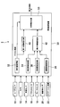
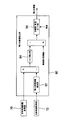
- FIG. 1 is a block diagram showing the vehicle control system of the first embodiment.
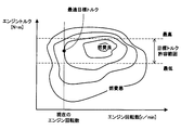
- FIG. 2 is a characteristic diagram showing the relationship between the engine speed and the fuel consumption in the allowable torque range.
- FIG. 3 is a characteristic diagram illustrating the synthesis of the first target value and the second target value.
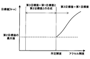
- FIG. 4 is a characteristic diagram showing the relationship among the first target value, the second target value, and the third target value.
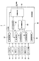
- FIG. 5 is a block diagram showing the vehicle control system of the second embodiment.
- FIG. 6 is a characteristic diagram illustrating the synthesis of the first target value and the second target value.
- FIG. 7 is a block diagram illustrating a second target value setting unit of the third embodiment.
- FIG. 8 is a block diagram illustrating a second target value setting unit of the fourth embodiment.
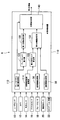
- FIG. 9 is a block diagram showing the vehicle control system of the fifth embodiment.
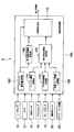
- FIG. 10 is a block diagram showing the vehicle control system of the sixth embodiment.
- a vehicle control system 2 shown in FIG. 1 is mounted on a vehicle and controls vehicle travel.
- the vehicle control system 2 includes various sensors for detecting the amount of driving operation of the driver, the traveling state of the host vehicle, the traveling state of the front vehicle traveling in front of the host vehicle, the road state where the host vehicle is traveling, and the like. It is mainly comprised from the apparatus and the vehicle control apparatus 30.
- FIG. 1 A vehicle control system 2 shown in FIG. 1 is mounted on a vehicle and controls vehicle travel.
- the vehicle control system 2 includes various sensors for detecting the amount of driving operation of the driver, the traveling state of the host vehicle, the traveling state of the front vehicle traveling in front of the host vehicle, the road state where the host vehicle is traveling, and the like. It is mainly comprised from the apparatus and the vehicle control apparatus 30.
- the vehicle control system 2 includes a radar sensor 10, a camera 12, a vehicle speed sensor 14, an accelerator sensor 16, a brake sensor 18, a steering angle sensor 20, a navigation device 22 and the like as various sensors and various devices.
- the radar sensor 10 scans and outputs laser light within a predetermined angle range to the front, side, and rear of the host vehicle, detects the reflected light, and the laser light is between the object that reflected the laser light.
- the distance from the time required to reciprocate to the object and the direction in which the object exists are determined from the direction in which the laser beam is irradiated when the reflected light is detected.
- the radar sensor 10 is not limited to the one that uses laser light, but may use one that uses radio waves in the millimeter wave band or microwave band, or one that uses ultrasonic waves.
- the camera 12 images the front, side, and rear of the vehicle.
- Image data captured by the camera 12 is analyzed by an image analysis device (not shown), and it is detected whether an object existing in front, side, and rear of the host vehicle is a vehicle or an obstacle.
- the vehicle speed sensor 14 detects the current vehicle speed of the host vehicle, and the accelerator sensor 16 detects the amount of depression of the accelerator pedal.
- the brake sensor 18 detects the depression amount of the brake pedal, and the steering angle sensor 20 detects the steering angle of the steering.
- the navigation device 22 includes GPS and map data.
- the navigation device 22 measures the position of the host vehicle based on the GPS signal received from the GPS satellite, maps the position of the host vehicle on the map data, and guides the travel route of the host vehicle.
- the vehicle control device 30 communicates with other ECUs via a microcomputer including a CPU, ROM, RAM, flash memory, an A / D conversion circuit, an input / output interface (I / O), and an in-vehicle LAN. It has a circuit.
- the operation amount acquisition unit 32, the vehicle information acquisition unit 34, the front vehicle information acquisition unit 36, the road information acquisition unit 38, and the first target value setting unit are realized by software such as microcomputer hardware and a control program. 40, a second target value setting unit 42, and a target value synthesizing unit 50.
- the operation amount acquisition unit 32 acquires the depression amount of the accelerator pedal from the accelerator sensor 16 as the driving operation amount of the driver, acquires the depression amount of the brake pedal from the brake sensor 18, and the steering angle of the steering from the steering angle sensor 20. Etc.
- the operation amount acquisition unit 32 calculates the steering speed of the steering by the driver from the amount of change in the steering angle of the steering.
- the vehicle information acquisition unit 34 acquires the engine speed, the host vehicle speed, the generator speed, and the like as the travel information of the host vehicle. Furthermore, the vehicle information acquisition unit 34 acquires an optimal target torque from the map shown in FIG. 2 so that the fuel consumption is optimal within the range of engine torque that is allowable for the current engine speed.
- the front vehicle information acquisition unit 36 detects from the radar sensor 10, the camera 12, and the like that there is a forward vehicle traveling in front of the host vehicle, and uses the inter-vehicle distance between the front vehicle and the host vehicle as travel information of the preceding vehicle. The vehicle speed of the vehicle ahead is acquired.
- the road information acquisition unit 38 acquires, as road information, the gradient of the road ahead of which the host vehicle is traveling, the degree of the curve, and the like from the map DB provided in the navigation device 22.
- the first target value setting unit 40 sets the target torque requested by the driver performing a driving operation based on the driving operation amount of the driver acquired by the operation amount acquiring unit 32 when the traveling of the host vehicle is controlled.
- One target value is set from a map or the like.
- the first target value setting unit 40 is a target torque requested by the driver operating the accelerator pedal based on the accelerator opening that is the amount of depression of the accelerator pedal acquired by the operation amount acquiring unit 32. Is set as the first target value for controlling the traveling of the host vehicle.
- the second target value setting unit 42 includes the travel information of the host vehicle acquired by the vehicle information acquisition unit 34, the travel information of the preceding vehicle acquired by the front vehicle information acquisition unit 36, and the host vehicle acquired by the road information acquisition unit 38. Based on the road information in front of the vehicle, an optimal target torque when the vehicle travel is controlled by automatic control is set as a second target value from a map or the like so as to improve the fuel consumption as much as possible.
- the target value synthesizing unit 50 synthesizes the first target value set by the first target value setting unit 40 and the second target value set by the second target value setting unit 42 to control the traveling of the host vehicle. Is set as the third target value.
- the target value synthesis unit 50 synthesizes the first target value and the second target value and sets the third target value if the accelerator opening is less than the predetermined opening as a predetermined threshold. To do.
- the target value synthesis unit 50 determines that the driver strongly desires to accelerate the host vehicle, and uses the second target value set by automatic control.
- the first target value set based on the driver's accelerator operation amount is set as the third target value.
- an engine control device (not shown) is configured as an electric drive source such as a throttle opening for a gasoline engine and a fuel injection amount of a fuel injection valve for a diesel engine. If a motor is provided, the amount of current supplied to the electric motor is controlled. Thereby, the output torque of the engine is controlled to the third target value.
- the target value synthesizing unit 50 sets the third target value by synthesizing the first target value and the second target value with the predetermined opening of the accelerator opening as a boundary, and sets the first target value to the third target.
- the third target value is set so that the third target value matches before and after switching at the predetermined opening.
- the first target value and the second target value are synthesized so that the third target value approaches the first target value as the accelerator opening increases and approaches the predetermined opening.
- the target value synthesis unit 50 changes the third target value within a range in which the driver feels that the traveling state of the host vehicle does not change before and after the switching of the third target value at the predetermined opening. May be.
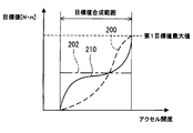
- the target value composition unit 50 composes the first target value 200 and the second target value 202 to set the third target value 210
- the first target value 200 and the second target value 200 are combined.
- the third target value 210 is set so as to be between the target value 202.
- the first target value or the second target value is set as the third target value 210.
- the target value synthesizing unit 50 synthesizes the first target value 200 and the second target value 202 to set the third target value 210, and the first target value 200 and the second target value 202 are within the accelerator opening range.
- the third target value 210 is set from the following equations (1) and (2) so as to be between:
- Third target value second target value ⁇ (second target value ⁇ first target value) * f1 ⁇ (second target value ⁇ first target value) / second target value ⁇ (1)
- Third target value second target value + (first target value ⁇ second target value) * f2 ⁇ (first target value ⁇ second target value) / (first target value maximum value ⁇ second target value) ⁇ ...
- the first target value maximum value is the first target value within the accelerator opening range where the first target value 200 and the second target value 202 are combined to set the third target value 210. Is the maximum value.
- the target value synthesis unit 50 synthesizes the first target value and the second target value to set the third target value. On the other hand, if the accelerator opening is equal to or greater than the predetermined opening, the target value synthesis unit 50 sets the first target value as the third target value without using the second target value.
- the target value synthesizing unit 50 synthesizes the first target value and the second target value to set the third target value.
- the third target value appropriate for controlling the vehicle travel can be set by reflecting the amount of operation of the accelerator pedal by the driver while receiving.
- the target value synthesis unit 50 sets the first target value as the third target value without using the second target value.
- the increase / decrease direction of the difference between the second target value and the first target value, the second target value, the increase / decrease direction of the difference with the third target value matches. That is, the magnitude relationship between the second target value set based on the automatic control and the first target value set based on the driving operation amount of the driver is compared with the second target value set based on the automatic control and the actual value. This can be reflected in the magnitude relationship with the third target value when the vehicle travel is controlled.
- the magnitude relationship between the second target value set based on the automatic control and the first target value set based on the driving operation amount of the driver can be appropriately reflected in the third target value.
- the target value synthesis unit 50 sets the third target value so that the third target value matches before and after switching at the predetermined opening degree.
- the target value requested by the driver for the vehicle travel control by the driving operation matches the target value requested by the automatic control for the vehicle travel control. It is.
- the driver's request for vehicle travel control and the vehicle for automatic control can be obtained.
- the request for the travel control can be appropriately reflected in the vehicle travel control actually executed by the vehicle control device 30.
- the second target value is set so as to improve the fuel consumption as much as possible, and the second target value and the first target are combined to set the third target value when actually controlling the vehicle travel, Fuel consumption can be improved while reflecting the amount of driving operation of the driver.
- the vehicle control system 4 of the second embodiment shown in FIG. 5 differs from the vehicle control system 2 of the first embodiment in that a maximum value is set as the second target value.
- the other configuration of the vehicle control system 4 is substantially the same as that of the vehicle control system 2.
- the maximum value setting unit 62 sets the maximum value of the second target value when the automatic control controls the vehicle travel according to the accelerator opening by the driving operation of the driver. For example, the maximum value of the second target value is increased as the accelerator opening increases.
- the second target value setting unit 64 acquires the travel information of the host vehicle acquired by the vehicle information acquisition unit 34, the travel information of the preceding vehicle acquired by the front vehicle information acquisition unit 36, and the road information acquisition.
- the maximum value is output as the second target value.
- the second target value setting unit 64 outputs the second target value as it is to the target value synthesis unit 50 when the second target value is equal to or less than the maximum value.
- the target value synthesizing unit 50 synthesizes the first target value and the second target value to set the third target value if the accelerator opening is less than the predetermined opening. If the opening is equal to or greater than the predetermined opening, the first target value is set as the third target value without using the second target value.
- the second target value setting unit 64 When the second target value exceeds the maximum value, the second target value setting unit 64 outputs the maximum value as the second target value. Accordingly, although automatic control support for vehicle travel control is received, it is possible to prevent the automatic control support from becoming too large, and to appropriately reflect the request for vehicle travel according to the driving operation amount of the driver.
- the second target value setting unit 80 of the third embodiment shown in FIG. 7 is a torque value by automatic control so that the target inter-vehicle distance is set based on the traveling state of the host vehicle and the preceding vehicle. Set the target value.
- Other configurations of the vehicle control device of the third embodiment are substantially the same as those of the vehicle control device 30 of the first embodiment.
- the front vehicle-to-vehicle distance acquisition unit 70 acquires the inter-vehicle distance between the host vehicle and the front vehicle when there is a front vehicle traveling in front of the host vehicle based on the output of the radar sensor 10 or the camera 12.
- the host vehicle speed acquisition unit 72 acquires the host vehicle speed that is the speed of the host vehicle based on the output of the vehicle speed sensor 14.
- the second target value setting unit 80 includes a minimum inter-vehicle distance calculation unit 82, a torque calculation unit 84, and a target value / vehicle speed guard unit 86.
- the minimum inter-vehicle distance calculation unit 82 calculates the minimum inter-vehicle distance necessary for avoiding a collision with the preceding vehicle based on the own vehicle speed acquired from the own vehicle speed acquisition unit 72. In order to avoid a collision between the host vehicle and the preceding vehicle, the minimum inter-vehicle distance calculation unit 82 sets the minimum inter-vehicle distance longer as the host vehicle speed increases.
- the minimum inter-vehicle distance calculation unit 82 may set the minimum inter-vehicle distance based on the relative speed of the host vehicle with respect to the preceding vehicle. In this case, the minimum inter-vehicle distance calculation unit 82 sets the minimum inter-vehicle distance longer as the relative speed of the own vehicle with respect to the preceding vehicle increases and the speed at which the own vehicle approaches the preceding vehicle increases.
- the torque calculation unit 84 sets the difference inter-vehicle distance calculated by subtracting the minimum inter-vehicle distance calculated by the minimum inter-vehicle distance calculation unit 82 from the actual inter-vehicle distance between the host vehicle and the preceding vehicle as a margin for the inter-vehicle distance. Then, for example, the torque calculation unit 84 multiplies the difference inter-vehicle distance by a predetermined coefficient K, and calculates a torque value to be subtracted from the second target value previously calculated at the subsequent stage of the torque calculation unit 84.
- the coefficient K is set to a negative value.
- the previous second target value may be increased so that the differential inter-vehicle distance is shortened. Therefore, when the differential inter-vehicle distance is multiplied by a coefficient K, the torque calculated by the torque calculation unit 84 Becomes negative. And the absolute value of the negative torque which the torque calculation part 84 calculates becomes large, so that the difference inter-vehicle distance becomes long.
- the torque calculation unit 84 calculates. Torque is positive. And the absolute value of the positive torque which the torque calculation part 84 calculates becomes large, so that the negative absolute value of the difference inter-vehicle distance becomes large.
- the torque calculation unit 84 calculates the value of the torque to be subtracted from the previous second target value in the subsequent stage of the torque calculation unit 84 based on the difference inter-vehicle distance instead of multiplying the difference inter-vehicle distance by the coefficient K. May be.
- the target value / vehicle speed guard unit 86 sets the second target value as the torque guard value when the torque obtained by subtracting the torque calculated by the torque calculation unit 84 from the torque represented by the previous second target value becomes equal to or greater than the torque guard value. .
- the second target value is set to a negative value so that the host vehicle speed decreases when the current host vehicle speed exceeds the vehicle speed guard value set by the speed limit or the like.
- the negative absolute value of the second target value is increased as the speed difference obtained by subtracting the vehicle speed guard value from the host vehicle speed increases.
- the second target value can be set so that the host vehicle and the preceding vehicle have an appropriate inter-vehicle distance.
- the second target value setting unit 100 of the fourth embodiment shown in FIG. 8 sets the second target value so that the own vehicle, the front vehicle, and the rear vehicle have an appropriate inter-vehicle distance.
- Other configurations of the vehicle control device of the fourth embodiment are substantially the same as those of the vehicle control device 30 of the first embodiment.
- the surrounding vehicle information acquisition unit 90 of the third embodiment shown in FIG. 8 is based on the output of the radar sensor 10 or the camera 12, and the actual front inter-vehicle distance that is the actual inter-vehicle distance between the own vehicle and the preceding vehicle, and the own vehicle. And the actual rear inter-vehicle distance, which is the actual inter-vehicle distance between the vehicle and the rear vehicle.
- the second target value setting unit 100 includes a front-rear inter-vehicle distance calculation unit 102 and a target value / vehicle speed guard unit 86 having substantially the same configuration as that of the third embodiment.
- the front-rear inter-vehicle distance calculation unit 102 acquires the actual front inter-vehicle distance and the actual rear inter-vehicle distance acquired by the surrounding vehicle information acquisition unit 90, the road gradient in front of the host vehicle acquired by the road information acquisition unit 38, and the host vehicle speed acquisition. Based on the host vehicle speed acquired by the unit 72, the optimal inter-vehicle distance between the host vehicle, the front vehicle, and the rear vehicle is calculated.
- the front-rear vehicle distance calculation unit 102 calculates the minimum front inter-vehicle distance with the front vehicle and the minimum rear inter-vehicle distance with the rear vehicle based on the host vehicle speed acquired by the host vehicle speed acquisition unit 72.
- the front-rear inter-vehicle distance calculation unit 102 sets the front minimum inter-vehicle distance longer as the host vehicle speed increases in order to avoid a collision between the host vehicle and the preceding vehicle.
- the front-rear inter-vehicle distance calculation unit 102 sets the minimum rear inter-vehicle distance longer as the host vehicle speed decreases in order to avoid a collision between the host vehicle and the rear vehicle.
- the front-rear inter-vehicle distance calculation unit 102 shortens the minimum front inter-vehicle distance and the minimum rear inter-vehicle distance, If the road ahead of the vehicle is a downhill, the front minimum inter-vehicle distance and the rear minimum inter-vehicle distance are increased.
- the front-rear inter-vehicle distance calculation unit 102 calculates a front differential inter-vehicle distance as a difference between the actual forward inter-vehicle distance and the forward minimum inter-vehicle distance, and calculates a backward differential inter-vehicle distance as a difference between the actual rear inter-vehicle distance and the rear minimum inter-vehicle distance.
- the front-rear inter-vehicle distance calculation unit 102 equalizes the margin of the inter-vehicle distance between the host vehicle, the front vehicle, and the rear vehicle by calculating an average value of the front difference vehicle distance and the rear difference vehicle distance.
- the front-rear inter-vehicle distance calculation unit 102 adds the average value of the calculated forward differential inter-vehicle distance and rear differential inter-vehicle distance to the minimum front inter-vehicle distance and the minimum rear inter-vehicle distance, respectively, and calculates the optimum front inter-vehicle distance and the optimal rear inter-vehicle distance. calculate.
- the inter-vehicle distance between the host vehicle, the front vehicle and the rear vehicle is set to the optimal inter-vehicle distance. Can do.
- the torque calculation unit 84 follows the difference in the front vehicle distance between the actual front inter-vehicle distance and the optimum front inter-vehicle distance or the rear inter-vehicle distance difference between the actual rear inter-vehicle distance and the optimum rear inter-vehicle distance.
- the torque value to be subtracted from the previous second target value is calculated from a map or the like.
- the previous second target value may be increased so that the front inter-vehicle distance difference is shorter than the current one. Therefore, the torque calculated by the torque calculation unit 84 is negative. Value. And the absolute value of the negative torque which the torque calculation part 84 calculates becomes large, so that the front inter-vehicle distance difference becomes long.
- the torque calculated by the torque calculation unit 84 is positive. Value. And the absolute value of the positive torque which the torque calculation part 84 calculates becomes large, so that the negative absolute value of the front inter-vehicle distance difference becomes large.
- the target value / vehicle speed guard unit 86 when the torque obtained by subtracting the torque calculated by the torque calculation unit 84 from the torque represented by the previous second target value becomes equal to or greater than the torque guard value. Set the value to the torque guard value. Further, the second target value is set to a negative value so that the host vehicle speed decreases if the current vehicle speed of the host vehicle exceeds a vehicle speed guard value set by a speed limit or the like.
- the second target value is set so that the own vehicle, the front vehicle, and the rear vehicle have an appropriate inter-vehicle distance. Can be set.
- the vehicle control device 110 sets the brake torque as the first target value based on the depression amount of the brake pedal as the driving operation amount of the driver. Further, the regenerative torque generated by the generator driven by the engine rotation is set as the second target value.
- the vehicle control device 110 is different from the first embodiment in that the first target value and the second target value are combined and a third target value that acts as a braking force for the engine output torque is set.
- the vehicle control device 110 includes a front vehicle information acquisition unit 36, a road information acquisition unit 38, a brake pedal operation amount acquisition unit 112, a generator rotation speed acquisition unit 114, a brake torque calculation unit 120, and a maximum regenerative torque calculation.
- the brake pedal operation amount acquisition unit 112 acquires the depression amount of the brake pedal from the brake sensor 18.
- the generator rotational speed acquisition unit 114 acquires the rotational speed of the on-vehicle generator from a rotational speed sensor installed in the generator or an engine rotational speed.
- the brake torque calculation unit 120 calculates the brake torque based on the brake pedal depression amount acquired by the brake pedal operation amount acquisition unit 112.
- the maximum regenerative torque calculation unit 122 calculates the maximum value of the regenerative torque that is generated when the generator generates electric power, based on the rotation speed of the generator acquired by the generator rotation speed acquisition unit 114.
- the first target value setting unit 130 sets the brake torque calculated by the brake torque calculation unit 120 as the first target value.
- the second target value setting unit 132 includes a maximum generator regenerative torque calculated by the maximum regenerative torque calculation unit 122, a distance between the front vehicle and the host vehicle acquired by the front vehicle information acquisition unit 36, and a road information acquisition unit.
- the regenerative torque is set as a second target value for automatic control based on the slope of the road ahead, the degree of curve, and the like on which the host vehicle acquired by the vehicle 38 is traveling.
- the target value synthesizing unit 140 synthesizes the first target value set by the first target value setting unit 130 and the second target value set by the second target value setting unit 132 to the engine output torque of the host vehicle.
- a third target value is set as the target value of the braking force.
- the target value synthesis unit 140 synthesizes the first target value and the second target to obtain the third target value. Set.
- the target value composition unit 140 determines that the driver has depressed the brake pedal greatly in order to avoid collision with an object ahead, and uses the second target value. First, the first target value is set as the third target value.
- the target value synthesis unit 140 synthesizes the first target value and the second target value to set the third target value.
- the target value composition unit 140 sets the first target value as the third target value without using the second target value.
- the target value composition unit 140 synthesizes the first target value and the second target value to set the third target value. It is possible to set an appropriate third target value for controlling the vehicle traveling by reflecting the depression amount of the brake pedal by the driver while receiving the traveling support.
- the target value composition unit 140 sets the first target value as the third target value without using the second target value.
- the vehicle control system 8 of the sixth embodiment shown in FIG. 10 is different from the first embodiment in that the vehicle control device 150 sets the steering amount of the wheel as the first target value, the second target value, and the third target value. Is different.
- the vehicle control device 150 includes a steering operation amount acquisition unit 152, a blinker information acquisition unit 154, a parallel vehicle information acquisition unit 156, a lane / curve information acquisition unit 158, a first target value setting unit 160, and a second target value.
- a setting unit 162 and a target value synthesis unit 170 are provided.
- the steering operation amount acquisition unit 152 acquires the steering angle and steering speed of the steering from the steering angle sensor 20.
- the winker information acquisition unit 154 acquires whether the winker indicates the right direction or the left direction.
- the parallel vehicle information acquisition unit 156 uses the radar sensor 10 and the camera as the parallel vehicle information traveling in the lane adjacent to the lane in which the host vehicle is traveling, such as the presence / absence of the parallel vehicle, the distance between the host vehicle and the vehicle speed. 12 from.
- the lane / curve information acquisition unit 158 acquires from the navigation device 22 information on the lane of the road on which the host vehicle is traveling and how much the road is curved.
- the first target value setting unit 160 sets the steering amount and the steering speed for the wheel as the first target value based on the steering angle and steering speed of the steering acquired by the steering operation amount acquisition unit 152.
- the second target value setting unit 162 steers the wheels as automatic control based on the above-described direction direction of the blinker, information on parallel vehicles traveling in the adjacent lane, and road information on which the host vehicle is traveling. The amount and the steering speed are set as the second target value.
- the second target value setting unit 162 The wheel steering speed is set faster than when the vehicle is not traveling in the lane.
- the target value composition unit 170 sets the first target value as the first target value.
- the third target value output by combining the second target value is faster than the steering speed indicated by the first target value set by the driver steering the steering.
- the host vehicle can be moved to the right lane before another vehicle traveling in the right lane of the host vehicle gets too close to the host vehicle.
- the second target value setting unit 162 is configured such that when the turn signal direction is on the right side, the turn signal direction direction is on the left side.
- a second target value that is a target value of the steering amount for the wheel is set large.
- the second target value setting unit 162 determines that the direction of the turn signal is on the left side and the direction of the turn signal is on the right side.
- the second target value that is the target value of the steering amount for the wheel is set to be large.
- the second target value setting unit 162 can set the second target value according to the degree of the curve of the road and the lane changing direction.
- the target value synthesis unit 170 synthesizes the first target value and the second target value when the steering angle or steering speed of the driver acquired by the steering operation amount acquisition unit 152 is less than a predetermined threshold set accordingly. Then, the steering amount and the steering speed for the wheel are set as the third target value.
- the target value synthesis unit 170 is large in order for the driver to avoid an object ahead, Alternatively, it is determined that the steering is operated quickly, and the first target value is set as the third target value without using the second target value.
- the target value synthesis unit 170 synthesizes the first target value and the second target value to generate the third target value. Set.
- the target value composition unit 170 uses the first target value as the third target value without using the second target value.
- the target value synthesis unit 170 synthesizes the first target value and the second target value to generate the third target. Since the value is set, it is possible to set an appropriate third target value for controlling the vehicle travel while reflecting the steering operation amount by the driver while receiving the travel support by the automatic control.
- the target value composition unit 170 uses the first target value as the third target value without using the second target value. Set as. Thereby, when the control request
- the driver's driving operation amount for example, when the accelerator opening, the brake pedal depression amount, and the steering operation amount are equal to or greater than a predetermined threshold set for each driving operation amount, The first target value was set as the third target value without using the second target value.
- the first target value set based on the driving operation amount is equal to or greater than a predetermined threshold value
- the first target value may be set as the third target value without using the second target value.
- the second target value setting unit 64 may output 0 as the second target value.
- the maximum value setting unit 62 may not be installed, and the target value synthesis unit 50 may set the maximum value of the second target value. Then, the target value synthesis unit 50 may determine whether or not the second target value exceeds the maximum value.
- the functions of one component in the above embodiment may be distributed as a plurality of components, or the functions of a plurality of components may be integrated into one component. Further, at least a part of the configuration of the above embodiment may be replaced with another configuration having the same function. Moreover, you may abbreviate
- a vehicle control system including the vehicle control device as a constituent element, a program for causing a computer to function as the vehicle control device, a recording medium recording the program, a vehicle control method, etc.
- Various forms can also be used as embodiments.
- the operation amount acquisition unit corresponds to an operation amount acquisition unit.
- the first target value setting units 40, 130, and 160 correspond to a first setting unit and a first setting unit.
- the second target value setting units 42, 64, 80, 100, 132, 162 correspond to a second setting unit and a second setting unit.
- the target value combining units 50, 140, and 170 correspond to a third setting unit and a third setting unit.
- the maximum value setting unit 62 corresponds to maximum value setting means.
- the brake pedal operation amount acquisition unit 112 corresponds to an operation amount acquisition unit and an operation amount acquisition unit.
- the steering operation amount acquisition unit 152 corresponds to an operation amount acquisition unit and an operation amount acquisition unit.
Landscapes
- Engineering & Computer Science (AREA)
- Automation & Control Theory (AREA)
- Transportation (AREA)
- Mechanical Engineering (AREA)
- Human Computer Interaction (AREA)
- Control Of Driving Devices And Active Controlling Of Vehicle (AREA)
Priority Applications (2)
| Application Number | Priority Date | Filing Date | Title |
|---|---|---|---|
| DE112016000826.0T DE112016000826T5 (de) | 2015-02-20 | 2016-02-09 | Fahrzeugsteuervorrichtung |
| US15/551,564 US10315654B2 (en) | 2015-02-20 | 2016-02-09 | Vehicle control device |
Applications Claiming Priority (2)
| Application Number | Priority Date | Filing Date | Title |
|---|---|---|---|
| JP2015-031742 | 2015-02-20 | ||
| JP2015031742A JP6369351B2 (ja) | 2015-02-20 | 2015-02-20 | 車両制御装置 |
Publications (1)
| Publication Number | Publication Date |
|---|---|
| WO2016132709A1 true WO2016132709A1 (ja) | 2016-08-25 |
Family
ID=56688959
Family Applications (1)
| Application Number | Title | Priority Date | Filing Date |
|---|---|---|---|
| PCT/JP2016/000661 Ceased WO2016132709A1 (ja) | 2015-02-20 | 2016-02-09 | 車両制御装置 |
Country Status (4)
| Country | Link |
|---|---|
| US (1) | US10315654B2 (enExample) |
| JP (1) | JP6369351B2 (enExample) |
| DE (1) | DE112016000826T5 (enExample) |
| WO (1) | WO2016132709A1 (enExample) |
Families Citing this family (2)
| Publication number | Priority date | Publication date | Assignee | Title |
|---|---|---|---|---|
| KR20180051274A (ko) * | 2016-11-08 | 2018-05-16 | 현대자동차주식회사 | 전방 차량의 주행 정보를 이용한 차량의 주행 제어 방법 |
| DE102018221860A1 (de) * | 2018-12-17 | 2020-07-02 | Volkswagen Aktiengesellschaft | Verfahren und Assistenzsystem zur Vorbereitung und/oder Durchführung eines Spurwechsels |
Citations (5)
| Publication number | Priority date | Publication date | Assignee | Title |
|---|---|---|---|---|
| JPH04300781A (ja) * | 1991-03-29 | 1992-10-23 | Mazda Motor Corp | 移動車の走行制御装置 |
| JPH07172337A (ja) * | 1993-09-27 | 1995-07-11 | Daimler Benz Ag | 車両の進行方向を制御されて保持するかじ取り装置 |
| JPH10152063A (ja) * | 1996-11-26 | 1998-06-09 | Toyota Motor Corp | 車両の操舵制御装置 |
| JP2010282344A (ja) * | 2009-06-03 | 2010-12-16 | Toyota Motor Corp | 運転情報記録装置 |
| JP2011131838A (ja) * | 2009-12-25 | 2011-07-07 | Toyota Motor Corp | 走行支援装置 |
Family Cites Families (8)
| Publication number | Priority date | Publication date | Assignee | Title |
|---|---|---|---|---|
| US4542460A (en) * | 1982-02-16 | 1985-09-17 | Weber Harold J | Driving aid indicator for economical operation of automatic transmission equipped motor vehicle |
| JP3654074B2 (ja) * | 1999-08-27 | 2005-06-02 | トヨタ自動車株式会社 | 複数の原動機を備えた車両の制御装置 |
| US7512477B2 (en) * | 2004-11-12 | 2009-03-31 | Volvo Trucks North America, Inc. | Systems and methods for guiding operators to optimized engine operation |
| US20060207822A1 (en) * | 2005-01-27 | 2006-09-21 | Taylor Kermit O | Differential steering application for trailer spotter vehicles |
| JP4265646B2 (ja) | 2006-11-14 | 2009-05-20 | トヨタ自動車株式会社 | クルーズコントロール制御の設定車速変更装置 |
| JP4661920B2 (ja) | 2008-08-18 | 2011-03-30 | トヨタ自動車株式会社 | クルーズコントロール制御の設定車速変更装置 |
| JP4973687B2 (ja) | 2009-05-13 | 2012-07-11 | トヨタ自動車株式会社 | 走行支援装置 |
| JP5618767B2 (ja) | 2010-10-29 | 2014-11-05 | アイシン精機株式会社 | 車両の横方向運動制御装置 |
-
2015
- 2015-02-20 JP JP2015031742A patent/JP6369351B2/ja active Active
-
2016
- 2016-02-09 US US15/551,564 patent/US10315654B2/en active Active
- 2016-02-09 WO PCT/JP2016/000661 patent/WO2016132709A1/ja not_active Ceased
- 2016-02-09 DE DE112016000826.0T patent/DE112016000826T5/de not_active Withdrawn
Patent Citations (5)
| Publication number | Priority date | Publication date | Assignee | Title |
|---|---|---|---|---|
| JPH04300781A (ja) * | 1991-03-29 | 1992-10-23 | Mazda Motor Corp | 移動車の走行制御装置 |
| JPH07172337A (ja) * | 1993-09-27 | 1995-07-11 | Daimler Benz Ag | 車両の進行方向を制御されて保持するかじ取り装置 |
| JPH10152063A (ja) * | 1996-11-26 | 1998-06-09 | Toyota Motor Corp | 車両の操舵制御装置 |
| JP2010282344A (ja) * | 2009-06-03 | 2010-12-16 | Toyota Motor Corp | 運転情報記録装置 |
| JP2011131838A (ja) * | 2009-12-25 | 2011-07-07 | Toyota Motor Corp | 走行支援装置 |
Also Published As
| Publication number | Publication date |
|---|---|
| US10315654B2 (en) | 2019-06-11 |
| JP2016153265A (ja) | 2016-08-25 |
| JP6369351B2 (ja) | 2018-08-08 |
| DE112016000826T5 (de) | 2017-11-30 |
| US20180029595A1 (en) | 2018-02-01 |
Similar Documents
| Publication | Publication Date | Title |
|---|---|---|
| CN112739586B (zh) | 车辆控制装置 | |
| JP7553259B2 (ja) | 車両の走行制御装置 | |
| CN100515817C (zh) | 在前车辆的跟踪巡航控制系统和方法 | |
| US10689005B2 (en) | Traveling assist device | |
| JP7147524B2 (ja) | 車両制御装置 | |
| US20180126965A1 (en) | Vehicle control device, vehicle control method, and vehicle control program | |
| CN113348121B (zh) | 用于操作自适应速度调节器的方法和控制单元 | |
| JP2020019392A (ja) | 自動運転システム | |
| JP2017001485A (ja) | 車両の運転支援装置 | |
| US20190256104A1 (en) | Driver assistance control device of a vehicle, driver assistance control method of a vehicle and driver assistance system | |
| JP2017194396A (ja) | 表示装置 | |
| JP6659513B2 (ja) | 車両制御装置、車両制御方法、および車両制御プログラム | |
| JP2022139065A (ja) | 運転支援装置、運転支援方法、およびプログラム | |
| JP2020083262A (ja) | 車両制御システム | |
| JP2018176959A (ja) | 自動運転システム | |
| JP7522795B2 (ja) | 経路生成装置 | |
| JP7213149B2 (ja) | 車両制御装置、車両、車両制御装置の動作方法およびプログラム | |
| JP6558261B2 (ja) | 自動運転装置 | |
| JP6369351B2 (ja) | 車両制御装置 | |
| JP2006143009A (ja) | 車両の運転支援装置 | |
| US20230294673A1 (en) | Driving assistance device, driving assistance method, and storage medium | |
| US20230294675A1 (en) | Driving assistance device, driving assistance method, and storage medium | |
| US20230286505A1 (en) | Driving assistance apparatus | |
| US20230294674A1 (en) | Driving assistance device, driving assistance method, and storage medium | |
| US12291212B2 (en) | Driving force control device |
Legal Events
| Date | Code | Title | Description |
|---|---|---|---|
| 121 | Ep: the epo has been informed by wipo that ep was designated in this application |
Ref document number: 16752099 Country of ref document: EP Kind code of ref document: A1 |
|
| WWE | Wipo information: entry into national phase |
Ref document number: 112016000826 Country of ref document: DE |
|
| NENP | Non-entry into the national phase |
Ref country code: DE |
|
| 122 | Ep: pct application non-entry in european phase |
Ref document number: 16752099 Country of ref document: EP Kind code of ref document: A1 |