WO2016132439A1 - 試料気化ユニット及びガスクロマトグラフ - Google Patents
試料気化ユニット及びガスクロマトグラフ Download PDFInfo
- Publication number
- WO2016132439A1 WO2016132439A1 PCT/JP2015/054156 JP2015054156W WO2016132439A1 WO 2016132439 A1 WO2016132439 A1 WO 2016132439A1 JP 2015054156 W JP2015054156 W JP 2015054156W WO 2016132439 A1 WO2016132439 A1 WO 2016132439A1
- Authority
- WO
- WIPO (PCT)
- Prior art keywords
- cap
- opening
- seal
- elastic
- sample
- Prior art date
- Legal status (The legal status is an assumption and is not a legal conclusion. Google has not performed a legal analysis and makes no representation as to the accuracy of the status listed.)
- Ceased
Links
Images





Classifications
-
- G—PHYSICS
- G01—MEASURING; TESTING
- G01N—INVESTIGATING OR ANALYSING MATERIALS BY DETERMINING THEIR CHEMICAL OR PHYSICAL PROPERTIES
- G01N30/00—Investigating or analysing materials by separation into components using adsorption, absorption or similar phenomena or using ion-exchange, e.g. chromatography or field flow fractionation
- G01N30/02—Column chromatography
- G01N30/04—Preparation or injection of sample to be analysed
- G01N30/16—Injection
- G01N30/18—Injection using a septum or microsyringe
-
- G—PHYSICS
- G01—MEASURING; TESTING
- G01N—INVESTIGATING OR ANALYSING MATERIALS BY DETERMINING THEIR CHEMICAL OR PHYSICAL PROPERTIES
- G01N30/00—Investigating or analysing materials by separation into components using adsorption, absorption or similar phenomena or using ion-exchange, e.g. chromatography or field flow fractionation
- G01N30/02—Column chromatography
- G01N30/04—Preparation or injection of sample to be analysed
- G01N30/06—Preparation
- G01N30/12—Preparation by evaporation
-
- B—PERFORMING OPERATIONS; TRANSPORTING
- B05—SPRAYING OR ATOMISING IN GENERAL; APPLYING FLUENT MATERIALS TO SURFACES, IN GENERAL
- B05C—APPARATUS FOR APPLYING FLUENT MATERIALS TO SURFACES, IN GENERAL
- B05C17/00—Hand tools or apparatus using hand held tools, for applying liquids or other fluent materials to, for spreading applied liquids or other fluent materials on, or for partially removing applied liquids or other fluent materials from, surfaces
- B05C17/005—Hand tools or apparatus using hand held tools, for applying liquids or other fluent materials to, for spreading applied liquids or other fluent materials on, or for partially removing applied liquids or other fluent materials from, surfaces for discharging material from a reservoir or container located in or on the hand tool through an outlet orifice by pressure without using surface contacting members like pads or brushes
- B05C17/00503—Details of the outlet element
- B05C17/00506—Means for connecting the outlet element to, or for disconnecting it from, the hand tool or its container
-
- B—PERFORMING OPERATIONS; TRANSPORTING
- B05—SPRAYING OR ATOMISING IN GENERAL; APPLYING FLUENT MATERIALS TO SURFACES, IN GENERAL
- B05C—APPARATUS FOR APPLYING FLUENT MATERIALS TO SURFACES, IN GENERAL
- B05C17/00—Hand tools or apparatus using hand held tools, for applying liquids or other fluent materials to, for spreading applied liquids or other fluent materials on, or for partially removing applied liquids or other fluent materials from, surfaces
- B05C17/005—Hand tools or apparatus using hand held tools, for applying liquids or other fluent materials to, for spreading applied liquids or other fluent materials on, or for partially removing applied liquids or other fluent materials from, surfaces for discharging material from a reservoir or container located in or on the hand tool through an outlet orifice by pressure without using surface contacting members like pads or brushes
- B05C17/00503—Details of the outlet element
- B05C17/00516—Shape or geometry of the outlet orifice or the outlet element
-
- B—PERFORMING OPERATIONS; TRANSPORTING
- B65—CONVEYING; PACKING; STORING; HANDLING THIN OR FILAMENTARY MATERIAL
- B65D—CONTAINERS FOR STORAGE OR TRANSPORT OF ARTICLES OR MATERIALS, e.g. BAGS, BARRELS, BOTTLES, BOXES, CANS, CARTONS, CRATES, DRUMS, JARS, TANKS, HOPPERS, FORWARDING CONTAINERS; ACCESSORIES, CLOSURES, OR FITTINGS THEREFOR; PACKAGING ELEMENTS; PACKAGES
- B65D41/00—Caps, e.g. crown caps or crown seals, i.e. members having parts arranged for engagement with the external periphery of a neck or wall defining a pouring opening or discharge aperture; Protective cap-like covers for closure members, e.g. decorative covers of metal foil or paper
- B65D41/02—Caps or cap-like covers without lines of weakness, tearing strips, tags, or like opening or removal devices
- B65D41/28—Caps combined with stoppers
-
- G—PHYSICS
- G01—MEASURING; TESTING
- G01N—INVESTIGATING OR ANALYSING MATERIALS BY DETERMINING THEIR CHEMICAL OR PHYSICAL PROPERTIES
- G01N30/00—Investigating or analysing materials by separation into components using adsorption, absorption or similar phenomena or using ion-exchange, e.g. chromatography or field flow fractionation
- G01N30/02—Column chromatography
- G01N30/04—Preparation or injection of sample to be analysed
- G01N30/16—Injection
-
- G—PHYSICS
- G01—MEASURING; TESTING
- G01N—INVESTIGATING OR ANALYSING MATERIALS BY DETERMINING THEIR CHEMICAL OR PHYSICAL PROPERTIES
- G01N30/00—Investigating or analysing materials by separation into components using adsorption, absorption or similar phenomena or using ion-exchange, e.g. chromatography or field flow fractionation
- G01N30/02—Column chromatography
- G01N2030/022—Column chromatography characterised by the kind of separation mechanism
- G01N2030/025—Gas chromatography
-
- G—PHYSICS
- G01—MEASURING; TESTING
- G01N—INVESTIGATING OR ANALYSING MATERIALS BY DETERMINING THEIR CHEMICAL OR PHYSICAL PROPERTIES
- G01N30/00—Investigating or analysing materials by separation into components using adsorption, absorption or similar phenomena or using ion-exchange, e.g. chromatography or field flow fractionation
- G01N30/02—Column chromatography
- G01N30/04—Preparation or injection of sample to be analysed
- G01N30/06—Preparation
- G01N30/12—Preparation by evaporation
- G01N2030/126—Preparation by evaporation evaporating sample
-
- G—PHYSICS
- G01—MEASURING; TESTING
- G01N—INVESTIGATING OR ANALYSING MATERIALS BY DETERMINING THEIR CHEMICAL OR PHYSICAL PROPERTIES
- G01N35/00—Automatic analysis not limited to methods or materials provided for in any single one of groups G01N1/00 - G01N33/00; Handling materials therefor
- G01N35/02—Automatic analysis not limited to methods or materials provided for in any single one of groups G01N1/00 - G01N33/00; Handling materials therefor using a plurality of sample containers moved by a conveyor system past one or more treatment or analysis stations
- G01N35/04—Details of the conveyor system
- G01N2035/0401—Sample carriers, cuvettes or reaction vessels
- G01N2035/0403—Sample carriers with closing or sealing means
- G01N2035/0405—Sample carriers with closing or sealing means manipulating closing or opening means, e.g. stoppers, screw caps, lids or covers
Definitions
- the present invention relates to a sample vaporization unit that has a sample vaporization chamber for vaporizing a sample injected by a sampler and sends the sample vaporized in the sample vaporization chamber to an analysis column, and a gas chromatograph including the sample vaporization unit.
- a gas chromatograph is provided with a sample vaporizing unit for vaporizing a sample and feeding it to an analysis column.
- the sample vaporizing unit has a housing, and there is a space serving as a sample vaporizing chamber inside the housing, and a sample for injecting a sample into the sample vaporizing chamber at the top of the housing.
- An inlet is provided.
- the lower part of the sample vaporization chamber is connected to the analysis column, and the carrier gas is introduced from the upper part of the sample vaporization chamber.
- the sample vaporization chamber is heated to a high temperature, and the liquid sample injected into the sample vaporization chamber is vaporized by heat and sent to the analysis column by the carrier gas.
- the sample vaporization chamber inside the housing accommodates a cylindrical insert made of quartz glass or the like, and the sample injected from the sample injection port is vaporized inside the insert. Since the sample is vaporized inside the insert, the sample gas can be introduced into the analysis column without contacting the metal inner wall of the sample vaporization chamber.
- the insert Since the insert is in direct contact with the sample, it is a component that tends to become dirty due to adhesion of vaporization residue, etc. of the sample. Therefore, the insert is accommodated in the sample vaporizing chamber in a detachable state so that the insert can be periodically replaced and cleaned (see Patent Document 1).
- an opening leading to the sample vaporizing chamber is provided on the upper surface of the housing, and the opening is sealed by attaching a seal cap with an O-ring sandwiched therebetween. Yes.
- a sample injection port for injecting a sample by piercing a sample injection needle is provided in the seal cap.
- a septum for closing the sample injection port after the sample injection needle is pulled out is provided inside the seal cap.
- a protrusion is provided on the housing (lower assembly) side, and a slope for hooking the housing side protrusion on the seal cap (upper assembly) side is provided.
- a seal cap is mounted on a housing by hooking and rotating the seal cap to raise the protrusion along the slope (see Patent Document 2).
- JP 2009-92672 A Japanese Patent No. 4819462
- the sample vaporization unit in addition to facilitating the work of fixing the seal cap to the housing, it is also important to ensure that the sample vaporization chamber is kept airtight when the seal cap is fixed to the housing.
- the sealing cap in the conventional sample vaporizing unit, when the seal cap is fixed to the casing, the sealing cap is weakly tightened, and the sample vaporization chamber is not sufficiently sealed.
- the present invention makes it possible to easily attach and detach the seal cap of the sample vaporizing unit, and to ensure that the airtightness of the sample vaporizing chamber is maintained when the seal cap is fixed. It is the purpose.
- An embodiment of a sample vaporizing unit includes an insert, a housing, a seal cap, and a cap fixture.
- the housing has an internal space for accommodating the insert, and a cylindrical cap mounting portion in which an opening leading to the internal space is provided on the distal end side.
- An inclined groove having an end point is provided at the end position.
- the seal cap is detachably mounted on the cap mounting portion and seals the opening.
- the cap fixing tool is for attaching the seal cap to the cap mounting portion.
- the cap fixture has a cap holding part that engages the seal cap so that its outer peripheral surface can move in the circumferential direction, and an elastic part that is provided integrally with the cap holding part.
- the elastic portion has a protrusion that is fitted into the inclined groove on the outer peripheral surface of the cap mounting portion.
- the cap fixture is rotatably mounted on the cap mounting portion so that the protrusion slides along the inclined groove inside the inclined groove.
- the elastic part of the cap fixture has a spring property that generates an elastic force that presses the cap holding part toward the opening so that the seal cap seals the opening when the protrusion comes to the end of the inclined groove.
- One embodiment of a gas chromatograph according to the present invention comprises the above sample vaporization unit, an analysis column connected to the outlet of the sample vaporization unit and separating the sample that has passed through the sample vaporization unit, and a sample separated by the analysis column. And a detector for detection.
- an inclined groove is provided on the outer peripheral surface of a cap mounting portion provided on the housing side, and a protrusion of a cap fixture holding a seal cap is fitted into the inclined groove.
- the gas chromatograph of the present invention includes the sample vaporization unit of the present invention, it is easy to attach and detach the sample vaporization unit insert, and the efficiency of the maintenance work is improved.
- the protrusion is capped at the end point position of the inner surface of the inclined groove that slides with the protrusion when the protrusion moves from the start point to the end point side of the inclined groove.
- a recess is provided to be fitted to the distal end side of the holding portion to prevent the protrusion from moving toward the starting point.
- a plurality of inclined grooves are provided evenly in the circumferential direction of the cap mounting portion on the outer peripheral surface of the cap mounting portion. If it does so, a seal cap can be uniformly pressed to the opening part side in the circumferential direction, and the opening part can be more reliably sealed with the seal cap.
- the cap holding part and the elastic part of the cap fixture may be integrally formed. If it does so, it is excellent in an external appearance, and integral molding means, such as MIM (Metal * Injection * Molding), can be used.
- MIM Metal * Injection * Molding
- the cap fixture depending on the material of the cap fixture, particularly the material of the spring material constituting the elastic part, it may be expensive and difficult to process. In that case, it is difficult to form the elastic part integrally with the cap holding part. In such a case, the cap holding part and the elastic part may be formed as separate bodies and connected to each other. By forming the elastic part, which is a spring material, as a separate part from the cap holding part, and then connecting the cap holding part and the elastic part, the cap fixture can be manufactured even for difficult materials It becomes easy.
- annular elastic seal member surrounding the outer periphery of the insert is provided in the vicinity of the opening in the internal space, and on the opening side of the inner wall surface of the internal space, An annular pedestal that supports an elastic seal member that is inserted from the opening and surrounds the periphery of the insert is provided, and the elastic seal member is inserted into the internal space from the opening to the opening side of the seal cap.
- the cap fixture is provided with a lever for driving the cap fixture in the rotation direction. If it does so, it will become easy to rotate a cap fixing tool, and the work efficiency of mounting
- a flange portion protruding in the circumferential direction is provided on the outer peripheral surface of the seal cap, and the cap holding portion of the cap fixture has an annular shape having an inner diameter smaller than the outer diameter of the flange portion. It is preferable that the surface on the opening side engages with the flange portion to press the seal cap toward the opening side.
- the seal cap When the needle insertion part for inserting the needle for sample injection toward the inner space is provided on the surface opposite to the opening part of the seal cap, the seal cap is located on the opening side of the needle insertion part. It is preferable to provide a septum made of an elastic material that can be penetrated by the needle inserted from the insertion portion and closes the hole after the needle is pulled out. If it does so, the airtightness after pulling out the needle for sample injection can be maintained.
- the projecting portion becomes an elastic portion in consideration of the bending of the elastic portion so that it is perpendicular to the outer peripheral surface of the cap mounting portion when the relative displacement amount of the projecting portion from the seal holding portion becomes maximum. It is preferable to be provided. If it does so, when the stress concerning a projection part becomes the maximum, it will be in the state where the projection part was inserted in the inclined groove in the posture perpendicular to the peripheral face of a cap mounting part. Thereby, it is possible to prevent a large stress from acting only on a specific point of the protrusion, and it is possible to prevent the protrusion from being worn or damaged.
- the gas chromatograph of this embodiment includes a sample vaporizing unit 2, an analytical column 6, a detector 10, and a column oven 12.
- the flow path 4 on one end side of the analysis column 6 is connected to the outlet 2 a at the lower end of the sample vaporizing unit 2, and the flow path 8 on the other end side is connected to the detector 10.
- the analysis column 6 is accommodated in a column oven 12, and the sample vaporizing unit 2 and the detector 10 are attached to the upper part of the column oven 12.
- the sample vaporizing unit 2 accommodates a columnar insert 16 that forms a sample vaporizing chamber in the internal space of the housing 14, and the internal space in which the insert 16 is accommodated is heated by a heater 18.
- An opening 28 leading to the internal space that accommodates the insert 16 is provided on the upper surface of the housing 14, and the edge of the opening 28 protrudes in an annular shape upward from the upper surface of the housing 14.
- the cap mounting portion 20 is formed.
- a seal cap 22 is mounted on the cap mounting portion 20, and the opening 28 is sealed with the seal cap 22.
- the seal cap 22 is provided with a needle insertion portion 24 that opens upward and guides the sample injection needle descending from above to the internal space of the housing 14.
- a pipe 26 for supplying a carrier gas for feeding the sample gas vaporized in the sample vaporizing chamber 6 to the analysis column 6 is connected to the seal cap 22.
- the carrier gas from the pipe 26 is introduced between the upper end portion of the insert 16 and the needle insertion portion 24.
- the sample to be analyzed is injected into the housing 14 by the needle inserted into the housing 14 through the needle insertion portion 24 and is vaporized inside the insert 16 heated by the heater 18.
- the sample gas vaporized inside the insert 16 is introduced into the analysis column 6 by the carrier gas from the pipe 26, separated for each component by the analysis column 6, and then detected for each component by the detector 10.
- a detector such as a mass spectrometer may be connected further downstream of the detector 10.
- the present invention is also applied to such a gas chromatograph.
- the casing 14 of the sample vaporizing unit 2 has a prismatic shape in this embodiment.
- the shape of the housing 14 is not limited to a prismatic shape, and may be a cylindrical shape or other shapes.
- the housing 14 includes a space 14a (see FIG. 5; hereinafter referred to as an internal space 14a) for accommodating the insert 16 therein.
- the internal space 14a is a hole with a circular cross section that communicates from the upper surface of the housing 14 to the lower outlet 2a.
- the housing 14 is made of a metal material having good thermal conductivity.
- a heater 18 (see FIG. 1) is embedded in the casing 14 so as to surround the inner space 14 a, and the insert 16 accommodated in the inner space 14 a by the heater 18. It is supposed to be heated.
- the insert 16 is a cylindrical member made of quartz glass or the like.
- the opening 28 of the housing 14 is sealed with a seal cap 22.
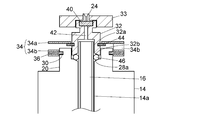
- the seal cap 22 includes a cylindrical seal cap main body portion 32 and a disc-shaped septum cover 33 attached to the uppermost portion of the seal cap main body portion 32.
- the needle insertion portion 24 is provided on the septum cover 33.
- the septum 40 is disposed at the top of the seal cap body 32, and the septum is disposed at the top of the seal cap body 32 so that the needle insertion portion 24 is located above the septum 40.
- a cover 33 is attached.
- the septum 40 can be penetrated by the needle for sample injection inserted from the needle insertion portion 24, and after the needle is pulled out, the through hole by the needle is closed by its elasticity.
- the septum 40 is made of an elastic material such as natural rubber or silicone rubber. A sample is discharged from the tip of the needle penetrating the septum 40 to the insert 16 side through the central through hole 42 of the seal cap main body 32.
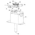
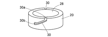
- the edge of the opening 28 on the upper surface of the housing 14 protrudes upward in an annular shape to form a cap mounting portion 20.
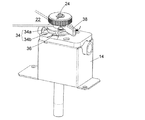
- the seal cap 22 is fixed to the cap mounting portion 20 by a cap fixing tool 34.
- the inclined grooves 30 are provided at two symmetrical positions on the outer peripheral surface of the cap mounting portion 20.
- the inclined groove 30 is inclined along the circumferential direction of the cap mounting portion 20 from the distal end side to the proximal end side of the cap mounting portion 20.
- the inclined groove 30 is for inserting and sliding the pin 36 (protrusion) of the cap fixture 34 attached to the seal cap 22. .
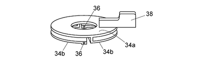
- the cap fixture 34 includes a disc-shaped cap holding portion 34a having a hole in the center, and a cap holding portion 34a on one surface side of the cap holding portion 34a. And two elastic portions 34b provided integrally. Assuming that the side of the cap fixture 34 where the elastic portion 34b is not provided is the front side and the side where the elastic portion 34b is provided is the back side, the cap fixture 34 is such that the back side faces the housing 14 side.
- the seal cap main body 32 is attached.
- the elastic part 34b of the cap fixture 34 is provided at a constant interval from the cap holding part 34a so as to draw an arc along the periphery of the cap holding part 34a.
- the base end of the elastic portion 34b is integrated with the cap holding portion 34a, but the tip is a free end. That is, the elastic portion 34b is a cantilever spring.
- a pin 36 that protrudes inward is provided at the tip of the elastic portion 34.
- the two elastic portions 34b have the same shape, and the pins 36 at the respective tips are arranged at positions facing each other.
- the cap holding portion 34a is provided with a lever 38 for holding and rotating the cap fixture 34.
- the cap holding portion 34a and the elastic portion 34b of the cap fixture 34 are integrally formed by a method such as cutting out from a metal block or MIM.
- the cap holding part 34a and the elastic part 34b may be connected after being formed as separate parts. In that case, the material of the cap holding part 34a and the elastic part 34b need not be the same.
- the cap holding part 34a engages with the seal cap main body part 32 so as to be movable in the circumferential direction of the outer peripheral surface thereof.
- a horizontal groove 32 a which is an annular concave portion provided in the circumferential direction is provided on the outer peripheral surface of the seal cap main body portion 32.
- a C-type retaining ring 44 is fitted in the horizontal groove 32a.
- the C-type retaining ring 44 is a C-shaped metal member having a notch in a part thereof, and has an inner diameter that is approximately the same as the outer diameter of the portion provided with the horizontal groove 32a of the seal cap main body 32.
- the seal cap body 32 has an outer diameter larger than the outer diameter of the portion where the horizontal groove 32a is not provided.
- the C-type retaining ring 44 forms a flange that protrudes in the circumferential direction from the outer peripheral surface of the seal cap main body 32.
- the inner diameter of the central hole of the cap holding portion 34a of the cap fixture 36 is larger than the outer diameter of the portion where the horizontal groove 32A of the seal cap main body 32 is not provided, and smaller than the outer diameter of the C-type retaining ring 44. ing.
- the seal cap main body portion 32 is fitted into the central hole of the cap holding portion 34a so that the C-shaped retaining ring 44 comes below the cap holding portion 34a.
- a flange that protrudes in the circumferential direction from the outer peripheral surface of the seal cap main body 32 may be provided integrally with the seal cap 32.
- the seal cap 22 is fixed to the cap mounting portion 20 by covering the cap mounting portion 20 with the seal cap 22 so that the pin 36 at the tip of the elastic portion 34b of the cap attachment 34 is fitted in the inclined groove 30 (state of FIG. 3). ), The cap fixture 34 is rotated in one direction (the clockwise direction in FIG. 6A) so as to slide the pin 36 along the inclined groove 30 (state in FIG. 4).
- the inclined groove 30 of the cap mounting portion 20 has a leading end side (upper end side) of the cap mounting portion 20 as a start point 30 a and a proximal end side (lower end side) of the cap mounting portion 20 as an end point 30 b. And it inclines along the outer peripheral surface of the cap mounting part 20 from the start point 30a to the end point 30b.
- a depression is provided at the end point 30b of the slope located on the tip side of the cap mounting portion 20 of the inclined groove 30. The depression at the end point 30b prevents the pin 36 reaching the end point 30b from being fitted and moving toward the start point 30a.
- the pin 36 that has reached the end point 30 b is prevented from moving to the start point 30 a side by itself due to the elastic force of the cap fixture 34.
- the pin 36 is fitted into the recess, so that the operator can feel a click, and the operator can easily finish the work of mounting the seal cap 22 on the cap mounting portion 20. I can know.
- an O-ring 46 (elastic seal) that seals a gap between the outer peripheral surface of the insert 16 and the inner wall surface of the internal space 14 a on the opening side of the internal space 14 a of the housing 14. Member) is arranged.
- the O-ring 46 is made of, for example, fluorine rubber.
- An annular pedestal 28a is provided in the vicinity of the opening 28 on the inner side wall of the housing 14 so that its inner diameter decreases as it goes downward, and an O-ring 46 is supported by the pedestal 28a.
- the seal cap main body 32 has a recess for accommodating the upper end of the insert 16 on the lower surface side, and the lower end thereof is accommodated in the opening 28 so as to sandwich the O-ring 46 between the base 28a. .
- the annular lower end surface of the seal cap main body 32 is inclined so that its inner diameter increases as it goes downward as opposed to the pedestal 28a.
- the elastic part 34b of the cap fixture 34 displaces the position of the pin 36 relative to the cap holding part 34a, and responds to the amount of displacement when the position of the pin 36 is displaced relative to the cap holding part 34a. It has a spring property that generates a restoring force.
- the cap fixture 34 rotates and the pin 36 reaches the end point of the inclined groove 30, the seal cap main body 32 is pressed into the opening 28 by the elastic force of the elastic portion 34b, and thereby the internal space 14a.
- the O-ring 46 is deformed to such an extent that the gas can be completely prevented from entering the gap between the inner wall surface and the outer peripheral surface of the insert 16.
- the cap fixture 34 has, for example, a cap holding portion 34a having a thickness of about 1 mm and an outer diameter of about 30 mm, an elastic portion 34b having a thickness of about 1.5 mm and an outer diameter of about 30 mm, and the cap holding portion 34a and the elastic portion 34b.
- the gap between them is about 2 mm.
- the material of the cap fixture 34 include stainless steel (for example, SUS630) subjected to precipitation hardening treatment or solid solution treatment, stainless steel as a spring material (for example, SUS301CSP or SUS304CSP), alloy steel (for example, SCM420).
- titanium alloys eg, Ti-6Al-4V (64 titanium), etc.
- copper alloys eg, beryllium copper, phosphor bronze, etc.
- the pin 36 Since the depression at the end point 30b is curved, if a force toward the start point 30a larger than the elastic force by the elastic portion 34b of the cap fixture 34 is applied to the pin 36, the pin 36 is released from the depression at the end point 30b and starts from the point 30a. You can move to the side. That is, when the seal cap 22 is removed from the casing 14, the cap fixture 34 is rotated in the opposite direction (counterclockwise direction in FIG. 6A) when the seal cap 22 is attached to the casing 14. The operator may apply force to the cap fixture 34.
- the cap fixture 34 is composed of two disk members (cap holding portion 34a and two elastic portions 34b), the surface area in contact with the outside air is large and plays the role of a radiation fin. . Thereby, cooling of the seal cap 22 is performed promptly.
- the elastic portion 34b of the cap fixture 34 has an arc shape, when the pin 36 slides inside the inclined groove 30 and the elastic portion 34b bends, the outer portion descends and the inside is deformed upward. It is possible. Therefore, in consideration of such deformation, as shown in FIG. 8, when the deformation amount of the elastic portion 34 b is maximized, the pin 36 is in a posture perpendicular to the outer peripheral surface of the cap mounting portion 20. As such, it may be provided so as to be inclined at the tip of the elastic portion 34b. Then, when the stress applied to the pin 36 is maximum, the pin 36 is inserted perpendicularly to the inclined groove 30, and the entire upper surface of the pin 36 is in contact with the wall surface of the inclined groove 30, thereby stress concentration. It is possible to prevent the pin 36 from being damaged or worn.
Landscapes
- Physics & Mathematics (AREA)
- Analytical Chemistry (AREA)
- General Health & Medical Sciences (AREA)
- Health & Medical Sciences (AREA)
- Life Sciences & Earth Sciences (AREA)
- Chemical & Material Sciences (AREA)
- Pathology (AREA)
- Biochemistry (AREA)
- Immunology (AREA)
- General Physics & Mathematics (AREA)
- Mechanical Engineering (AREA)
- Engineering & Computer Science (AREA)
- Geometry (AREA)
- Other Investigation Or Analysis Of Materials By Electrical Means (AREA)
- Sampling And Sample Adjustment (AREA)
Abstract
Description
2a 試料気化ユニット出口部
4,8 流路
6 分析カラム
10 検出器
12 カラムオーブン
14 筐体
14a 筐体の内部空間
16 インサート
18 ヒータ
20 キャップ装着部
22 シールキャップ
24 ニードル挿入部
26 キャリアガス供給用の配管
28 開口部
30 傾斜溝
30a 傾斜溝の始点
30b 傾斜溝の終点
32 シールキャップ本体部
32a 水平溝
33 セプタムカバー
34 キャップ固定具
34a キャップ保持部
34b 弾性部
36 ピン
38 レバー
40 セプタム
42 貫通孔
44 C型止め輪
46 Oリング
Claims (11)
- 筒状のインサートと、
前記インサートを収容する内部空間、及び先端側に前記内部空間に通じる開口部が設けられている円筒形状のキャップ装着部を有する筐体であって、前記キャップ装着部の外周面に、前記キャップ装着部の先端側から基端側へ向かって周方向に沿って傾斜し、最も前記キャップ装着部の先端側の位置に始点、最も前記キャップ装着部の基端側の位置に終点をもつ傾斜溝が設けられている筐体と、
前記筐体の前記キャップ装着部に着脱可能に装着されて前記開口部を封止するシールキャップと、
前記シールキャップに対しその外周面の周方向に移動可能に係合するキャップ保持部及び前記キャップ保持部に連結された弾性部を有し、前記弾性部に前記キャップ装着部の前記傾斜溝に嵌め込まれる突起部を有し、前記突起部が前記傾斜溝の内側で前記傾斜溝に沿って摺動するように前記キャップ装着部に回転可能に装着されたキャップ固定具であって、前記突起部が前記傾斜溝の終点にきたときに前記シールキャップが前記開口部を封止するように前記キャップ保持部を前記開口部側へ押圧する弾性力を発生させるバネ性を有するキャップ固定具と、を備えた試料気化ユニット。 - 前記突起部が前記傾斜溝の前記始点から前記終点側へ移動する際に前記突起部と摺動する前記傾斜溝の内側面の前記終点の位置に、前記突起部を前記キャップ保持部の先端側へ嵌まり込ませて前記突起部の前記始点側への移動を抑止する窪みが設けられている請求項1に記載の試料気化ユニット。
- 前記キャップ装着部の外周面に、複数の前記傾斜溝が前記キャップ装着部の周方向に均等に設けられている請求項1又は2に記載の試料気化ユニット。
- 前記キャップ固定具の前記キャップ保持部と前記弾性部は一体として形成されている請求項1から3のいずれか一項に記載の試料気化ユニット。
- 前記キャップ固定具の前記キャップ保持部と前記弾性部は別体として形成され互いに連結されている請求項1から3のいずれか一項に記載の試料気化ユニット。
- 前記内部空間内の前記開口部近傍において前記インサートの前記開口部側外周を囲う円環状の弾性シール部材が設けられ、
前記内部空間の内側壁面における前記開口部側に、前記開口部から挿入され前記インサートの周囲を囲う前記弾性シール部材を支持する円環状の台座が設けられており、
前記シールキャップの前記開口部側に、前記開口部から前記内部空間内に挿入されて前記弾性シール部材を前記台座側へ押圧する押圧部が設けられ、
前記キャップ固定具の前記突起部が前記傾斜溝の前記終点にきたときに、前記シールキャップの前記押圧部によって前記台座側へ押圧された前記弾性シール部材が変形して前記インサートの外周面と前記内部空間の内側壁面との間の隙間を封止するように構成されている請求項1から5のいずれか一項に記載の試料気化ユニット。 - 前記キャップ固定具に該キャップ固定具を回転方向へ駆動するためのレバーが設けられている請求項1から6のいずれか一項に記載の試料気化ユニット。
- 前記シールキャップの外周面に周方向へ鍔状に突起した鍔部が設けられており、
前記キャップ固定具の前記キャップ保持部は、前記鍔部の外径よりも小さい内径をもつ円環形状を有し、その開口部側の面が前記鍔部と係合することで前記シールキャップを前記開口部側へ押圧するものである請求項1から7のいずれか一項に記載の試料気化ユニット。 - 前記シールキャップは、前記開口部とは反対側の面に前記内部空間に向かって試料注入用のニードルを挿入させるニードル挿入部を有するとともに、前記ニードル挿入部よりも前記開口部側に、前記ニードル挿入部から挿入されたニードルにより貫通可能でかつニードルが引き抜かれた後の孔を閉じる弾力性を有する弾性材料からなるセプタムを備えている請求項1から8のいずれか一項に記載の試料気化ユニット。
- 前記突起部は、前記突起部の前記シール保持部からの相対的な変位量が最大となったときに前記キャップ装着部の外周面に対して垂直になるように前記弾性部に設けられている請求項1から9のいずれか一項に記載の試料気化ユニット。
- 請求項1から10のいずれか一項に記載の試料気化ユニットと、
前記試料気化ユニットの出口部に接続され、前記試料気化ユニットを経た試料の分離を行なう分析カラムと、
前記分析カラムで分離された試料を検出する検出器と、を備えたガスクロマトグラフ。
Priority Applications (6)
| Application Number | Priority Date | Filing Date | Title |
|---|---|---|---|
| JP2017500158A JP6399200B2 (ja) | 2015-02-16 | 2015-02-16 | 試料気化ユニット及びガスクロマトグラフ |
| CN201580078846.XA CN107533037A (zh) | 2015-02-16 | 2015-02-16 | 试样气化单元及气相色谱仪 |
| PCT/JP2015/054156 WO2016132439A1 (ja) | 2015-02-16 | 2015-02-16 | 試料気化ユニット及びガスクロマトグラフ |
| US15/550,435 US10551359B2 (en) | 2015-02-16 | 2015-02-16 | Sample vaporization unit and gas chromatograph |
| EP15882543.0A EP3260857B1 (en) | 2015-02-16 | 2015-02-16 | Sample vaporization unit and gas chromatograph |
| CN202110804020.4A CN113484451B (zh) | 2015-02-16 | 2015-02-16 | 试样气化单元及气相色谱仪 |
Applications Claiming Priority (1)
| Application Number | Priority Date | Filing Date | Title |
|---|---|---|---|
| PCT/JP2015/054156 WO2016132439A1 (ja) | 2015-02-16 | 2015-02-16 | 試料気化ユニット及びガスクロマトグラフ |
Publications (1)
| Publication Number | Publication Date |
|---|---|
| WO2016132439A1 true WO2016132439A1 (ja) | 2016-08-25 |
Family
ID=56689311
Family Applications (1)
| Application Number | Title | Priority Date | Filing Date |
|---|---|---|---|
| PCT/JP2015/054156 Ceased WO2016132439A1 (ja) | 2015-02-16 | 2015-02-16 | 試料気化ユニット及びガスクロマトグラフ |
Country Status (5)
| Country | Link |
|---|---|
| US (1) | US10551359B2 (ja) |
| EP (1) | EP3260857B1 (ja) |
| JP (1) | JP6399200B2 (ja) |
| CN (2) | CN113484451B (ja) |
| WO (1) | WO2016132439A1 (ja) |
Cited By (3)
| Publication number | Priority date | Publication date | Assignee | Title |
|---|---|---|---|---|
| WO2018047348A1 (ja) * | 2016-09-12 | 2018-03-15 | 株式会社島津製作所 | 試料気化ユニット |
| JP2020128916A (ja) * | 2019-02-08 | 2020-08-27 | 株式会社オーバル | 変換器および流量計 |
| EP4293352A1 (en) | 2022-06-14 | 2023-12-20 | Shimadzu Corporation | Member coupling mechanism |
Families Citing this family (5)
| Publication number | Priority date | Publication date | Assignee | Title |
|---|---|---|---|---|
| JP6399200B2 (ja) * | 2015-02-16 | 2018-10-03 | 株式会社島津製作所 | 試料気化ユニット及びガスクロマトグラフ |
| US10781015B2 (en) * | 2018-07-05 | 2020-09-22 | Shimadzu Corporation | Member coupling mechanism |
| US12007034B2 (en) * | 2019-01-22 | 2024-06-11 | Totalenergies Onetech (Previously Totalenergies One Tech) | Injection valve for an analysis apparatus |
| US12078618B2 (en) * | 2019-06-10 | 2024-09-03 | Shimadzu Corporation | Gas chromatograph-mass spectrometer |
| CN120948124B (zh) * | 2025-10-16 | 2026-01-09 | 西南医科大学附属医院 | 消化内科呕吐物分腔取样装置 |
Citations (9)
| Publication number | Priority date | Publication date | Assignee | Title |
|---|---|---|---|---|
| JPH054006U (ja) * | 1991-06-28 | 1993-01-22 | ジーエルサイエンス株式会社 | ガスクロマトグラフ用検出器のノズル印加構造 |
| JPH11166933A (ja) * | 1997-10-02 | 1999-06-22 | F Hoffmann La Roche Ag | 試料カップの自動取扱装置 |
| JP2004203489A (ja) * | 2002-12-23 | 2004-07-22 | Deutsche Sisi-Werke Gmbh & Co Betriebs Kg | 漏斗状に形成された流出路を備える封止要素 |
| JP2005005972A (ja) * | 2003-06-11 | 2005-01-06 | Tamron Co Ltd | 撮像素子清掃装置及びそれを備えたカメラシステム |
| JP3129007U (ja) * | 2006-11-15 | 2007-02-01 | 株式会社島津製作所 | ガスクロマトグラフ |
| JP2007504058A (ja) * | 2003-09-01 | 2007-03-01 | ミックスパック システムズ アーゲー | ストッパとバヨネット式連結手段を備えたおよびロッキング・リングとを含む配給装置 |
| JP2009092672A (ja) * | 2008-12-24 | 2009-04-30 | Shimadzu Corp | ガスクロマトグラフ |
| JP4819462B2 (ja) * | 2004-09-30 | 2011-11-24 | アジレント・テクノロジーズ・インク | 改良されたインレットシール機構を備えているガスクロマトグラフシステム |
| WO2015004757A1 (ja) * | 2013-07-10 | 2015-01-15 | 株式会社島津製作所 | 試料気化ユニット及びガスクロマトグラフ |
Family Cites Families (6)
| Publication number | Priority date | Publication date | Assignee | Title |
|---|---|---|---|---|
| US7316730B2 (en) * | 2002-03-15 | 2008-01-08 | Restek Corporation | Inlet double-seal assembly |
| CN2826428Y (zh) * | 2005-02-04 | 2006-10-11 | 安捷伦科技有限公司 | 具有改进密封装置的气相色谱仪进样口 |
| WO2010025570A1 (en) * | 2008-09-08 | 2010-03-11 | Mecanique Analytique | Temperature compensated valve for gas chromatography |
| EP2767301A1 (en) * | 2013-02-19 | 2014-08-20 | Clovershield, Inc. | Therapeutic vaporizer and components thereof |
| CN203241427U (zh) * | 2013-04-23 | 2013-10-16 | 李鹏 | 一种顶空进样器 |
| JP6399200B2 (ja) * | 2015-02-16 | 2018-10-03 | 株式会社島津製作所 | 試料気化ユニット及びガスクロマトグラフ |
-
2015
- 2015-02-16 JP JP2017500158A patent/JP6399200B2/ja active Active
- 2015-02-16 WO PCT/JP2015/054156 patent/WO2016132439A1/ja not_active Ceased
- 2015-02-16 US US15/550,435 patent/US10551359B2/en active Active
- 2015-02-16 EP EP15882543.0A patent/EP3260857B1/en active Active
- 2015-02-16 CN CN202110804020.4A patent/CN113484451B/zh active Active
- 2015-02-16 CN CN201580078846.XA patent/CN107533037A/zh active Pending
Patent Citations (9)
| Publication number | Priority date | Publication date | Assignee | Title |
|---|---|---|---|---|
| JPH054006U (ja) * | 1991-06-28 | 1993-01-22 | ジーエルサイエンス株式会社 | ガスクロマトグラフ用検出器のノズル印加構造 |
| JPH11166933A (ja) * | 1997-10-02 | 1999-06-22 | F Hoffmann La Roche Ag | 試料カップの自動取扱装置 |
| JP2004203489A (ja) * | 2002-12-23 | 2004-07-22 | Deutsche Sisi-Werke Gmbh & Co Betriebs Kg | 漏斗状に形成された流出路を備える封止要素 |
| JP2005005972A (ja) * | 2003-06-11 | 2005-01-06 | Tamron Co Ltd | 撮像素子清掃装置及びそれを備えたカメラシステム |
| JP2007504058A (ja) * | 2003-09-01 | 2007-03-01 | ミックスパック システムズ アーゲー | ストッパとバヨネット式連結手段を備えたおよびロッキング・リングとを含む配給装置 |
| JP4819462B2 (ja) * | 2004-09-30 | 2011-11-24 | アジレント・テクノロジーズ・インク | 改良されたインレットシール機構を備えているガスクロマトグラフシステム |
| JP3129007U (ja) * | 2006-11-15 | 2007-02-01 | 株式会社島津製作所 | ガスクロマトグラフ |
| JP2009092672A (ja) * | 2008-12-24 | 2009-04-30 | Shimadzu Corp | ガスクロマトグラフ |
| WO2015004757A1 (ja) * | 2013-07-10 | 2015-01-15 | 株式会社島津製作所 | 試料気化ユニット及びガスクロマトグラフ |
Cited By (6)
| Publication number | Priority date | Publication date | Assignee | Title |
|---|---|---|---|---|
| WO2018047348A1 (ja) * | 2016-09-12 | 2018-03-15 | 株式会社島津製作所 | 試料気化ユニット |
| US10859539B2 (en) | 2016-09-12 | 2020-12-08 | Shimadzu Corporation | Sample vaporization unit |
| JP2020128916A (ja) * | 2019-02-08 | 2020-08-27 | 株式会社オーバル | 変換器および流量計 |
| EP4293352A1 (en) | 2022-06-14 | 2023-12-20 | Shimadzu Corporation | Member coupling mechanism |
| JP2023182142A (ja) * | 2022-06-14 | 2023-12-26 | 株式会社島津製作所 | 部材連結機構 |
| US12498356B2 (en) | 2022-06-14 | 2025-12-16 | Shimadzu Corporation | Member linking mechanism |
Also Published As
| Publication number | Publication date |
|---|---|
| EP3260857A1 (en) | 2017-12-27 |
| EP3260857A4 (en) | 2019-01-16 |
| JPWO2016132439A1 (ja) | 2017-11-30 |
| US10551359B2 (en) | 2020-02-04 |
| EP3260857B1 (en) | 2023-03-29 |
| CN107533037A (zh) | 2018-01-02 |
| JP6399200B2 (ja) | 2018-10-03 |
| CN113484451B (zh) | 2023-10-13 |
| CN113484451A (zh) | 2021-10-08 |
| US20180128786A1 (en) | 2018-05-10 |
Similar Documents
| Publication | Publication Date | Title |
|---|---|---|
| JP6399200B2 (ja) | 試料気化ユニット及びガスクロマトグラフ | |
| JP6090446B2 (ja) | 試料気化ユニット及びガスクロマトグラフ | |
| US20220049776A1 (en) | Diaphragm valve | |
| JP6662389B2 (ja) | 開口封止構造体、試料気化ユニット及びガスクロマトグラフ | |
| JP6614331B2 (ja) | 部材連結機構及び部材連結方法 | |
| US10781015B2 (en) | Member coupling mechanism | |
| JP6540521B2 (ja) | 部材連結機構 | |
| WO2015037123A1 (ja) | 着脱機構、試料気化ユニット、水素炎イオン化検出器及びガスクロマトグラフ | |
| JP3129007U (ja) | ガスクロマトグラフ | |
| EP4293352B1 (en) | Member coupling mechanism | |
| JP3206105U (ja) | 試料気化ユニット及びそれを備えたガスクロマトグラフ | |
| JP6776271B2 (ja) | 圧力制御バルブ及び超臨界流体クロマトグラフ | |
| JP2013036920A (ja) | セプタム及び当該セプタムを使用した試料注入口 | |
| JP7218707B2 (ja) | 試料導入装置 | |
| JP2019032345A (ja) | 試料気化ユニット及びそれを備えたガスクロマトグラフ | |
| JP2015004646A (ja) | 酸素濃度測定装置 | |
| WO2018047348A1 (ja) | 試料気化ユニット | |
| CN113939895A (zh) | 气相色谱质量分析装置 |
Legal Events
| Date | Code | Title | Description |
|---|---|---|---|
| 121 | Ep: the epo has been informed by wipo that ep was designated in this application |
Ref document number: 15882543 Country of ref document: EP Kind code of ref document: A1 |
|
| ENP | Entry into the national phase |
Ref document number: 2017500158 Country of ref document: JP Kind code of ref document: A |
|
| NENP | Non-entry into the national phase |
Ref country code: DE |
|
| REEP | Request for entry into the european phase |
Ref document number: 2015882543 Country of ref document: EP |
|
| WWE | Wipo information: entry into national phase |
Ref document number: 15550435 Country of ref document: US |