WO2016129496A1 - 景品排出機構 - Google Patents
景品排出機構 Download PDFInfo
- Publication number
- WO2016129496A1 WO2016129496A1 PCT/JP2016/053376 JP2016053376W WO2016129496A1 WO 2016129496 A1 WO2016129496 A1 WO 2016129496A1 JP 2016053376 W JP2016053376 W JP 2016053376W WO 2016129496 A1 WO2016129496 A1 WO 2016129496A1
- Authority
- WO
- WIPO (PCT)
- Prior art keywords
- prize
- passage
- discharge
- capsule
- passage opening
- Prior art date
- Legal status (The legal status is an assumption and is not a legal conclusion. Google has not performed a legal analysis and makes no representation as to the accuracy of the status listed.)
- Ceased
Links
Images





Classifications
-
- G—PHYSICS
- G07—CHECKING-DEVICES
- G07F—COIN-FREED OR LIKE APPARATUS
- G07F17/00—Coin-freed apparatus for hiring articles; Coin-freed facilities or services
- G07F17/32—Coin-freed apparatus for hiring articles; Coin-freed facilities or services for games, toys, sports, or amusements
-
- G—PHYSICS
- G07—CHECKING-DEVICES
- G07F—COIN-FREED OR LIKE APPARATUS
- G07F11/00—Coin-freed apparatus for dispensing, or the like, discrete articles
- G07F11/46—Coin-freed apparatus for dispensing, or the like, discrete articles from movable storage containers or supports
- G07F11/50—Coin-freed apparatus for dispensing, or the like, discrete articles from movable storage containers or supports the storage containers or supports being rotatably mounted
- G07F11/52—Coin-freed apparatus for dispensing, or the like, discrete articles from movable storage containers or supports the storage containers or supports being rotatably mounted about horizontal axes
Definitions
- the present invention relates to a prize discharging mechanism for discharging a plurality of prizes stored inside a storage part one by one from the outlet.
- each capsule has a plurality of cylinders arranged in a row, and the capsules at the bottom of each cylinder are discharged in order, and the capsules at the bottom are discharged by the detection plate.
- a capsule dispensing device that detects the presence or absence of (for example, see Patent Document 1).
- Patent Documents 2 and 3 as prior art documents related to the present invention.
- Japanese Patent No. 3060804 Japanese Patent No. 4821103 Japanese Patent No. 4420287
- the presence or absence of the lowermost capsule is detected for each cylinder. That is, it is detected whether the capsule can be discharged next time for each cylinder.
- a discharge mechanism that rotates a disk-shaped distribution board and discharges capsules one by one through this rotation in accordance with the collection of the value.
- Such a discharge mechanism often collects the payment in advance.
- prepayment if the capsule cannot be discharged, it will be necessary to return the consideration.
- it is often difficult to return the consideration for example, when electronic currency is used as the consideration. For this reason, in such a device as well, it may be necessary to manage whether or not the capsule can be discharged next time. Furthermore, it may not be sufficient to confirm the remaining number of capsules that can be discharged next time.
- an object of the present invention is to provide a prize discharging mechanism capable of managing the number of prizes remaining including the inventory to be discharged not only the next time but also one after another.
- the prize discharge mechanism of the present invention is a prize discharge mechanism that discharges a plurality of prizes stored inside the storage part one by one from the discharge port to the outside, and has a size that allows the plurality of prizes to pass one by one.
- a first member having a plurality of opening portions each opening and one of the plurality of passage portions being arranged so as to correspond to the position of the discharge port, and each prize passes.
- a connecting port portion that is open, and is disposed between the first member and the discharge port so that the connection port portion corresponds to the position of the discharge port, and the rest other than the one passage port portion
- a second member that blocks the prizes so that the prizes do not pass through the passage openings and stays in the passage openings, a restricting member that restricts entry of the prizes into the one passage opening, and the remaining passage openings.
- a plurality of scenes that detect whether or not each prize remains for at least a part And the first member rotates with each prize staying at each passing port so that each passing port sequentially functions as the one passing port along the second member, and the plurality of prizes
- the detection sensor performs at least the detection with respect to two passage openings that function as the one passage opening sequentially in the next and successive times among the remaining passages in accordance with the rotation of the first member. is there.
- the figure which shows the front view in the example of FIG. 3 typically.
- FIG. 1 is a diagram schematically showing an appearance of a game system including a prize discharging mechanism according to an embodiment of the present invention and a game machine using the premium discharging mechanism.
- the game system 1 includes a prize discharge mechanism GP and two game machines GM.
- the premium discharging mechanism GP is a mechanism for providing a user with a premium stored therein.
- the prize discharge mechanism GP is used connected to these two game machines GM.
- the prize discharge mechanism GP includes, for example, a storage unit 6 and a discharge unit 7.
- the storage unit 6 is a part for storing a plurality of prizes. For example, a plurality of capsules 8 as prizes are stored in the storage unit 6.
- a front side lid 6a is provided on the front side of the storage unit 6, and an upper side lid 6b is provided on the upper side.
- the front side lid 6a and the upper surface side lid 6b are lid members for forming the front wall or upper surface of the storage unit 6.
- a space is formed inside the storage section 6 by the front side lid 6a and the upper surface side lid 6b.
- a hemispherical three-dimensional window 9 is provided in the front lid 6a.
- the storage unit 6 visually provides information on the capsule 8 inside through the window 9 to the outside.
- the capsule 8 is a capsule-type spherical container that accommodates various physical benefits (things) such as figures. That is, the capsule 8 contains an actual privilege (a prize).
- the discharge unit 7 is a part for providing the user with a free gift inside the storage unit 6.
- the discharge part 7 is formed with a lower discharge port 7a.
- the lower discharge port 7a is connected to a connection passage (not shown).
- the connection passage is a passage that connects the inside and the outside of the storage unit 6. That is, the lower discharge port 7a is an opening that connects the inside and the outside of the storage unit 6 through the connection passage.
- the capsule 8 of the storage part 6 is discharged
- the prize discharge mechanism GP discharges each capsule 8 inside the storage unit 6 one by one from the lower discharge port 7a to the outside when the prize condition is satisfied.
- the prize discharge mechanism GP is configured as a vendor unit (so-called gacha gacha) that appropriately provides the capsule 8 of the storage unit 6 to the user as an example.
- the game machine GM is configured as a business (commercial) game machine as an example.
- Commercial game machines are game machines that allow a predetermined range of games to be played for a fee or free of charge.
- the game machine GM provides a game for a fee.
- the game machine GM provides, for example, a game that uses the prize discharge mechanism GP in a range corresponding to the price in exchange for consumption of a predetermined price.
- an appropriate number of game machines GM are installed in a commercial facility such as a store.
- the game machine GM includes a housing C.
- the housing C is provided with a monitor MO.
- a transparent touch panel TP is superimposed on the surface of the monitor MO.
- the touch panel TP is a known input device that outputs a signal corresponding to a contact position of a finger or the like.
- a coin collecting mechanism SO is provided on the front surface of the housing C.
- the coin collection mechanism SO is a mechanism for executing collection and return of coins.
- the coin recovery mechanism SO has a coin insertion slot SO1 and a coin discharge slot SO2.
- the coin insertion slot SO1 is used for inserting coins
- the coin discharge slot SO2 is used for discharging coins.
- a predetermined value is consumed (paid) through a coin.
- the game machine GM may be provided with various input devices and output devices included in a normal business game machine such as a volume operation switch, a power switch, and a power lamp.
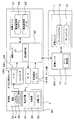
- FIG. 2 is a diagram illustrating a configuration of a main part of a control system of the prize discharging mechanism GP and the game machine GM.
- the game machine GM is provided with a control unit 10 as a computer and a storage unit 11.
- the control unit 10 is configured as a computer unit combining a microprocessor and various peripheral devices such as an internal storage device (for example, ROM and RAM) necessary for the operation of the microprocessor.
- a storage unit 11 is connected to the control unit 10.
- control unit 10 includes, for example, a speaker, a card reader (for example, using short-range wireless communication as well as a known game machine).
- Various output devices or input devices such as known devices that read various information recorded in the storage medium in a non-contact state can be connected. However, those illustrations are omitted.
- the storage unit 11 is configured by, for example, a magnetic recording medium, an optical recording medium, a flash SSD (Solid State Drive), or the like so that the storage can be held without power supply.
- the storage unit 11 stores a game program 14 and game data 15.
- the game program 14 is a computer program necessary for the game machine GM to provide a game.
- a game providing unit 17 is provided inside the control unit 10.
- the game providing unit 17 executes various processes necessary for providing a game.
- the game providing unit 17 is a logical device realized by a combination of computer hardware and a computer program. Various other logical devices may be provided inside the control unit 10. However, those illustrations are omitted.
- the game data 15 is data that can be referred to as the game program 14 is executed.
- the game data 15 includes, for example, image data and sound effect data.
- the image data is data for displaying various images necessary for the game.
- the sound effect data is data for reproducing various sounds necessary for the game.
- the game data 15 may include various other data necessary for the game. However, those illustrations are omitted.
- the prize discharge mechanism GP includes, as an example, a motor 18 as a drive source, a discharge detection sensor 19, and a capsule detection sensor DS as a prize detection sensor, in addition to the storage unit 6 described above.
- the prize discharge mechanism GP also includes a control unit 20 and a storage unit 21.
- the control unit 20 is configured as a computer unit in which a microprocessor and various peripheral devices such as an internal storage device (for example, ROM and RAM) necessary for the operation of the microprocessor are combined.
- a storage unit 21, a motor 18, a discharge detection sensor 19, and a capsule detection sensor DS are connected to the control unit 20.
- various other output devices or input devices may be connected to the control unit 20, for example. However, those illustrations are omitted.
- the storage unit 21 is configured by, for example, a magnetic recording medium, an optical recording medium, a flash SSD (Solid State Drive), or the like so that the storage can be held without supplying power.
- the storage unit 21 stores a prize management program 24 and a prize management data 25.
- the prize management program 24 is a computer program necessary for the prize discharge mechanism GP to manage the capsule 8 (including discharge).
- the prize management data 25 is data that can be referred to when the prize management program 24 is executed.
- a prize providing unit 27 is provided inside the control unit 20.
- the prize providing unit 27 executes various processes necessary for managing the prize.
- the prize providing unit 27 is a logical device realized by a combination of computer hardware and a computer program. Various other logical devices may be provided inside the control unit 20. However, those illustrations are omitted.
- the storage unit 6 includes a box 33, a delivery disk 34 as a first member, a bottom plate 35 as a second member, and a limiting spring 36 as a limiting member.
- the box part 33 is an upper part of the storage part 6.
- the box part 33 is a part which has the space for accommodating the capsule 8 inside as an example.
- the box part 33 forms the circumference
- the delivery disk 34 is a member for delivering the capsule 8 inside the storage unit 6 to the discharge unit 7.
- the delivery disk 34 is disposed below the box portion 33.
- the delivery disk 34 is disposed below each capsule 8 in order to deliver each capsule 8 stored in the box 33 to the discharge unit 7.
- the delivery disk 34 is rotationally driven by the motor 18 as an example.
- the delivery disk 34 delivers each capsule 8 located in order one by one so that the capsule 8 may be discharged
- the bottom disk 35 is a member disposed further below the delivery disk 34 so as to assist the delivery of the delivery disk 34.
- the limiting spring 36 is a spring arranged so as to partially limit the movement of each capsule 8 inside the storage unit 6.
- the capsule detection sensor DS is a sensor for detecting whether or not the capsule 8 is delivered. Specifically, as an example, the capsule detection sensor DS is used to detect the delivery status of the delivery disk 34.
- the capsule detection sensor DS includes, for example, a reader DS1 and a photosensor DS2.
- the photosensor DS2 is a well-known sensor using a light emitting element that emits infrared rays or the like.
- the photosensor DS2 outputs the detection result to the control unit 20. Further, as an example, the operation of the photosensor DS2 may be controlled by the control unit 20.
- the reader DS1 is a well-known device for reading information on an IC chip (a kind of RFID and sometimes called an IC tag).
- the reader DS1 functions as the capsule detection sensor DS by acquiring information from an IC chip, for example.
- each capsule 8 is provided with an IC chip 38.
- the contents such as the types of specific prizes accommodated in each capsule 8, the prize ID for identifying each prize 8a, the shipping time, the shipping location, etc. Is recorded.
- the reader DS1 provides (outputs) the reading result of the IC chip 38, that is, the acquired various information to the control unit 20.
- the control unit 20 detects the delivery status of the capsule 8 based on whether or not the information of the IC chip 38 is acquired.
- the reader DS1 functions as the capsule detection sensor DS depending on whether or not the information of the IC chip 38 is provided. Further, as an example, the operation of the reader DS1 may be controlled by the control unit 20.
- the motor 18 is a power source for rotationally driving the delivery disk 34 as described above.
- the operation of the motor 18 is controlled by the control unit 20.
- the discharge detection sensor 19 is a sensor for detecting the presence or absence of the capsule 8 discharged from the lower discharge port 7a.
- the discharge detection sensor 19 may be a known sensor that detects the presence or absence of the capsule 8 that passes through the lower discharge port 7a.
- the discharge detection sensor 19 may include a member that is pushed by the progress of the capsule 8 that passes through the lower discharge port 7a (the progress itself is not hindered). Further, the discharge detection sensor 19 may output a signal indicating discharge of the capsule 8 when pressed by the advance of the capsule 8.
- the discharge detection sensor 19 may be configured as described above as an example. Accordingly, the discharge detection sensor 19 is disposed near the lower discharge port 7a of the connection passage as an example. The detection result of the discharge detection sensor 19 is output to the control unit 20.
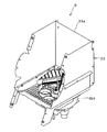
- FIG. 3 is a diagram schematically illustrating an example of a perspective view of the storage unit 6 in a state where the front side cover 6a and the upper surface side cover 6b are removed.
- a space for accommodating a large number of capsules 8 is formed inside the box portion 33.
- the box part 33 has the enclosure part 33a.
- the enclosure part 33a is a member that forms a side wall that surrounds the internal space. More specifically, the surrounding part 33a forms surrounding side walls other than the front side wall formed by the front side lid 6a among the side walls forming the internal space of the storage unit 6.
- a cylindrical part BH extending downward in a cylindrical shape is formed below the box part 33.
- FIG. 4 is a diagram schematically showing a front view in the example of FIG. 3, that is, a front view of the storage section 6 with the front side cover 6a and the upper side cover 6b removed.
- a motor 18 is disposed below the storage unit 6. More specifically, the motor 18 is disposed further below the cylindrical portion BH as an example.
- FIG. 5 is a diagram schematically showing a left side view in the example of FIG. 3, that is, a side view of the storage unit 6 with the front side cover 6a and the upper side cover 6b removed.
- a rotation detection switch 40 and a reader DS ⁇ b> 1 are further provided below the storage unit 6.
- the rotation detection switch 40 is, for example, a switch for outputting a signal along with the rotation of the delivery disk 34 or the like.
- the rotation detection switch 40 functions as a sensor that detects the rotation of the delivery disk 34. That is, for example, the rotation detection switch 40 functions as a unit for acquiring the rotation status of the delivery disk 34, for example.
- the rotation detection switch 40 outputs the detection result, that is, information on the rotation status of the delivery disk 34 and the like to the control unit 20 as an example.
- the reader DS1 includes an antenna control board 41 and an antenna board 42 as an example.
- the antenna substrate 42 is a well-known unit for executing reading of the IC chip 38.
- the antenna control board 41 is a well-known unit for controlling the operation of the antenna board 42. That is, the reader DS1 is arranged so as to read the IC chip 38 included in each capsule 8 inside the box portion 33 from further below the cylindrical portion BH.
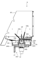
- FIG. 6 is a diagram schematically showing a cross-sectional view taken along line VI-VI in FIG.
- a photosensor DS2 is disposed below the cylindrical portion BH, similarly to the reader DS1. That is, the reader DS1 and the photosensor DS2 are disposed on the opposite side of the delivery disk 34 with the bottom surface board 35 interposed therebetween.
- a delivery disk 34 and a bottom disk 35 are arranged in order from the top inside the cylindrical part BH.
- the delivery disk 34 is rotatably arranged, while the bottom board 35 is fixedly arranged so as not to move.
- each passage port portion CH is a portion that opens so as to connect the upper surface side 34U and the bottom surface side 34D of the delivery disk 34.
- each passage opening portion CH is a portion that opens so that each capsule 8 positioned above the delivery disk 34 can pass below the delivery disk 34. Therefore, each passage opening CH is formed so as to penetrate the delivery disk 34 in the thickness (height) direction. Further, each passage opening CH is formed at a predetermined height (depth) with reference to the size (radius) of the capsule 8.
- an extension 34b is also formed in a part of the opening on the upper side of each passage opening CH. The extension part 34b is a part extending so as to extend the height of each passage opening part CH. As a result, each passage opening CH is formed with a portion higher than the other portions by the extension 34b in a part on the upper side.
- the bottom plate 35 is formed in a plate shape along the bottom surface of the cylindrical portion BH.
- the bottom board 35 closes the lower side of each passage opening portion CH and functions as the bottom surface of each passage opening portion CH. That is, the bottom board 35 is arranged so as to prevent the passage of each capsule 8 and to keep each capsule 8 in each passage opening CH.
- a stirring unit 43 is provided at the center of the delivery disk 34 and the bottom board 35.
- the stirring unit 43 is a unit for stirring the capsule 8 inside the storage unit 6.
- the stirring unit 43 is disposed so as to penetrate through the central parts of the delivery disk 34 and the bottom board 35 as an example.
- the stirring unit 43 is rotationally driven by the motor 18 in the same manner as the delivery disk 34.
- the stirring unit 43 is provided with two stirring springs 43a at the top.
- Each agitation spring 43a is arranged to extend obliquely upward intersecting the vertical direction in order to improve the agitation efficiency.
- the stirring spring 43 a rotates together with the stirring unit 43. That is, the stirring unit 43 rotates so as to affect the state (position, etc.) of each capsule 8 inside the storage unit 6 by the stirring spring 43a.
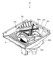
- FIG. 7 is a diagram schematically showing the storage unit 6 in a state where the enclosure 33a is further removed in the example of FIG.
- the delivery disk 34 has six passage openings CH.
- each passage port part CH is formed in the magnitude
- each passage opening CH is formed in, for example, a circular shape that is larger than each capsule 8 so as not to interfere with the passage of each capsule 8 and so that the plurality of capsules 8 do not enter. That is, as an example, each passage port portion CH is formed in a size and shape through which each capsule 8 passes one by one.
- each passage port portion CH rotates with the capsule 8 staying there, that is, the capsule 8 accommodated therein.
- the extension part 34b of each passage port part CH is arrange
- the extension part 34b is provided above the opposite side of the rotation direction RD of each passage port part CH.
- the delivery disk 34 sequentially delivers the capsules 8 in the respective passage openings CH in the rotation direction through such passage openings CH.
- a limiting spring 36 is disposed above the delivery disk 34. More specifically, the limiting spring 36 is disposed so as to cross over one of the six passage openings CH. As a result, the limiting spring 36 limits the penetration of the capsule 8 into this one passage opening CH. On the other hand, the limiting spring 36 is disposed at a position higher than the height of the capsule 8 in the state accommodated in each passage opening CH. For this reason, the restricting spring 36 does not hinder the capsule 8 that moves so as to be positioned downward together with the passage openings CH as the delivery disk 34 rotates. In other words, the limiting spring 36 is disposed so as to limit the direct entry of the capsule 8 into the passage port CH positioned below, while allowing the capsule 8 to move downward along with the delivery of the delivery disk 34. ing.
- FIG. 8 is a diagram schematically showing a plan view of the storage section 6 in the example of FIG. However, in the example of FIG. 8, illustration of the stirring spring 43a is omitted for convenience of explanation.
- an upper discharge port 7 b is provided below the storage unit 6.
- the upper discharge port 7b is an opening for discharging the capsule 8 inside the storage unit 6 to the outside.
- the upper discharge port 7b opens toward a connection passage located below. That is, as described above, the upper discharge port 7b is connected to the lower discharge port 7a through the connection passage.
- the upper discharge port 7b has a circular shape that is slightly larger than the capsule 8 so as to suppress the intrusion of another capsule 8 while discharging one capsule 8 as an example, similarly to the passage port portion CH. Is formed.
- connection port 35a is a portion that opens to provide the capsule 8 to the upper discharge port 7b.
- connection port portion 35a opens so as to connect the upper surface side and the bottom surface side of the bottom surface board 35. Therefore, the upper surface side of the bottom panel 35 is connected to the upper discharge port 7b through the connection port portion 35a.
- connection port part 35a is arrange
- the connection port portion 35a is disposed at a position of a passage port portion CH (hereinafter sometimes referred to as a connection passage port portion CH1 for convenience) located below the restriction spring 36.
- a passage port portion CH hereinafter sometimes referred to as a connection passage port portion CH1 for convenience
- connection port portion 35a is formed in a circular shape that is slightly larger than the capsule 8 so as to suppress the intrusion of the other capsule 8 while allowing the passage of one capsule 8 in the same manner as the passage port portion CH and the like.
- the bottom board 35 is formed so as to provide the upper outlet 7b with the capsule 8 that has passed through the connection passage portion CH1 by the connection portion 35a at the connection passage portion CH1.
- the bottom board 35 is formed so as to block the lower side of each passage opening CH in the remaining five passage openings CH other than the connection passage opening CH1.
- sensor holes 45 as small openings are further provided at the positions of the remaining five passage openings CH other than the connection passage openings CH1 of the bottom panel 35.
- the sensor hole 45 is a hole used by the capsule detection sensor DS to detect the capsule 8.
- the sensor hole 45 is, for example, a hole for the reader DS1 and the photosensor DS2 to output radio waves and light to the capsules 8 in the respective passage openings CH.
- the sensor hole 45 is opened so as to connect the upper surface side and the bottom surface side of the bottom panel 35 in the same manner as the connection port portion 35a.
- the sensor hole 45 is smaller than the connection port portion 35a. Specifically, it is much smaller than the diameter of the capsule 8. For this reason, the capsule 8 cannot pass through the sensor hole 45.
- the reader DS1 and the photosensor DS2 are disposed under the cylindrical portion BH. Therefore, a hole 45 for the sensor is similarly provided in the cylindrical portion BH.
- the delivery disk 34 is disposed so that one of the passage openings CH corresponds to the position of the upper discharge opening 7b. That is, the delivery disk 34 is arranged so that one of the passage openings CH functions as the connection passage opening CH1.
- the position of each passage port portion CH changes in order as the delivery disk 34 rotates. Specifically, for example, the position of each passage port portion CH changes so that each passage port portion CH functions as the connection passage port portion CH1 in order in the rotation direction RD with this rotation.
- the passage port portion CH (which may be referred to as the next passage portion CH2 for the sake of convenience hereinafter) located immediately before the rotational direction RD of the connection passage portion CH1 is two times before the next time.
- Positioned passage openings CH (hereinafter sometimes referred to as passage openings CH3 one after another for convenience) function as the connection passage openings CH1 one after another. The same applies to the subsequent passage openings CH.
- each passage port part CH rotates with the capsule 8 inside.
- the capsules 8 accommodated therein are delivered to the position of the upper discharge port 7b so that each passage port portion CH functions in order as the connection passage portion CH1.
- a connection port portion 35a is provided at the position of the connection passage port portion CH1.
- the connection passage port portion CH1 is connected to the upper discharge port 7b via the connection port portion 35a, unlike the other passage port portions CH.
- each capsule 8 is provided to the upper discharge port 7b at the position of the connection passage port portion CH1.
- the delivery disk 34 provides the capsules 8 inside the storage unit 6 to the upper discharge port 7b one by one through each passage port portion CH by such rotation.
- connection passage part CH1 functions as one passage part of the present invention.
- the remaining five passage openings other than the connection passage opening CH1 function as the remaining passage openings of the present invention.
- the capsule detection sensor DS is provided for each passage port CH other than the connection passage port CH1. That is, five capsule detection sensors DS respectively corresponding to the five passage openings CH are arranged below the cylindrical portion BH through the sensor hole 45. As an example, the five capsule detection sensors DS are configured by one reader DS1 and four photosensors DS2. Specifically, as an example, the reader DS1 is disposed below the passing port portion CH1 immediately before the connecting passing port portion CH1 in the rotation direction RD, that is, below the next passing port portion CH2. Therefore, in the next passage port portion CH2, in other words, information recorded on the IC chip 38 of each capsule 8 is acquired via the reader DS1 at a position immediately before being discharged.
- the photosensor DS2 is arranged below the other four passage openings CH, that is, the respective passage openings CH other than the connection passage opening CH1 and the next passage opening CH2.
- the next passage port portion CH2 functions as the next passage portion of the present invention.
- an insertion port 46 for the stirring unit 43 is formed in the center of the delivery disk 34 and the bottom plate 35.
- the insertion slot 46 is formed so as to penetrate the delivery disk 34 and the bottom board 35.
- a stirring portion 43 is inserted into the insertion port 46. Therefore, the movement of the central part of the capsule 8 is restricted by the stirring unit 43. Specifically, intrusion from the central portion side to the connection passage port portion CH1 is suppressed. As a result, the capsule 8 discharged from the upper discharge port 7b is limited to delivery by the delivery disk 34.
- the prize discharge mechanism GP is configured in this way.
- the game machine GM may provide various games that use the prize discharge mechanism GP.
- the game machine GM may provide an action game, a role playing game, a simulation game, a puzzle game, a shooting game, and the like.
- the game machine GM provides a prize discharging mechanism GP for providing a prize when, for example, a prize condition is satisfied.
- the prize condition may be satisfied according to, for example, a game play situation. Alternatively, it may be satisfied simply by paying consideration.
- the delivery process is a process for delivering the capsule 8 to the delivery disk 34. More specifically, the delivery process is executed in order to control the rotation of the delivery disk 34 and its stop as an example.
- the position adjustment process is a process for optimizing the communication between the reader DS1 and the IC chip 38 of the capsule 8. More specifically, as an example, the position adjustment process is executed to shake the capsule 8 so that the reader DS1 and the antenna of the IC chip 38 are parallel.
- the delivery process is realized by the control unit 20 through the routine of FIG. 9, and the position adjustment process is realized by the control unit 20 through the routine of FIG. More specifically, the routines of FIGS. 9 and 10 are executed through the prize providing unit 27 of the control unit 20 as an example.
- control unit 20 or the control unit 10 of the game machine GM executes various well-known processes for controlling the prize discharging mechanism GP or for executing the game, for example. This includes various processes using detection results of the reader DS1 and the photosensor DS2. As such a process, for example, the control unit 20 executes a process for managing the number of stocks (whether there are 5 or more). Alternatively, the control unit 10 of the game machine GM, for example, controls the game according to the number of stocks (for example, when there is no remaining number, the use of the prize discharge mechanism GP is stopped, or the game using the prize discharge mechanism GP). To stop the provision of the service). However, these detailed explanations are omitted.
- FIG. 9 is a diagram showing an example of a flowchart of a delivery processing routine for realizing delivery processing.
- the routine of FIG. 9 is executed when the rotation condition is satisfied.
- the rotation condition is satisfied when, for example, a prize condition is satisfied. That is, as an example, the prize condition may function as the rotation condition.
- the prize providing unit 27 first rotates the delivery disk 34 in step S11. That is, the delivery disk 34 starts to rotate. Specifically, the delivery disk 34 is driven by the motor 18. For this reason, the premium providing unit 27 controls the motor 18 so that the delivery disk 34 starts rotating in step S11.
- the prize providing unit 27 stops the rotation of the delivery disk 34 when the delivery condition is satisfied.
- the delivery condition is satisfied when the passage port CH functioning as the connection passage port CH1 is changed. More specifically, as an example, it is satisfied when the next passage port portion CH2 comes to the position of the connection passage portion portion CH1, that is, when the next passage port portion CH2 rotates to a position that functions as the connection passage portion CH1. .
- the detection result of the rotation detection switch 40 is used. That is, as an example, the position where the next passage port portion CH2 functions as the connection passage portion CH1 may be detected by the rotation detection switch 40.
- the drive shaft for the motor 18 to rotate the delivery disk 34 is a protrusion for causing the rotation detection switch 40 to detect the position where the next passage port portion CH2 functions as the connection passage portion CH1.
- a notification unit (not shown) may be provided.
- the rotation detection switch 40 may detect the position of the next passage port CH2 by this notification unit.
- the rotation detection switch 40 may detect the rotation angle. That is, the prize providing unit 27 stops the rotation of the delivery disk 34 when the next passage port portion CH2 rotates to the position where it functions as the connection passage portion CH1 in step S12. On the other hand, the prize providing unit 27 continues the rotation of the delivery disk 34 until the delivery condition is satisfied.
- the delivery condition is, for example, that a predetermined time has elapsed. The case may also be satisfied.
- next step S13 the number of times that the next passage port portion CH2 has rotated to the position where it functions as the connection passage portion CH1 is counted up. Specifically, if this is the first time, it is counted up as “1”. Similarly, when the next passage port portion CH2 rotates to the position where it functions as the connection passage portion portion CH1 for the second time, that is, until the position where the next passage portion CH3 functions as the connection passage portion portion CH1 after the next passage portion CH2. When it rotates, it is counted up as “2”. The same applies thereafter.
- the gift providing unit 27 determines whether or not the stop condition is satisfied.
- the stop condition is satisfied, for example, when the capsule 8 is discharged from the lower discharge port 7a.
- the discharge of the capsule 8 is determined based on the detection result of the discharge detection sensor 19, for example. That is, it is satisfied when the capsule 8 is correctly delivered by the delivery disk 34.
- the stop condition may be satisfied, for example, when the count number is counted up to “5” based on the count result of step S13. In this case, it is assumed that the capsule 8 is not correctly delivered by the delivery disk 34, but the capsule 8 is not accommodated in any of the passage openings CH. That is, it is assumed that the capsule 8 is not in stock. Even in this case, the stop condition is satisfied.
- step S14 If the determination result in step S14 is a negative result, that is, if the stop condition is not satisfied, the gift providing unit 27 returns to step S11 and executes the subsequent processing again. That is, the processes in steps S11 to S13 are repeated. On the other hand, if the determination result in step S14 is a positive result, that is, if the stop condition is satisfied, the prize providing unit 27 ends the current routine. Thereby, the rotation of the delivery disk 34 is controlled so that the capsule 8 is delivered to the upper discharge port 7b through each passage port portion CH. For example, even when the capsule 8 is not accommodated in the next passage port portion CH2 or the like, the delivery disk 34 continues to rotate until the passage port portion CH that accommodates the capsule 8 functions as the connection passage portion CH1.
- the delivery disk 34 is controlled so as to continue rotating until the capsule 8 is discharged from the upper discharge port 7b.
- the rotation is stopped even if the capsules 8 are not discharged.
- FIG. 10 is a diagram illustrating an example of a flowchart of a position adjustment process routine for realizing the position adjustment process.
- the routine of FIG. 10 is executed, for example, every time the passage port portion CH that functions as the connection passage portion CH1 is changed. That is, the routine of FIG. 10 is executed each time the delivery condition is satisfied as an example.
- the prize providing unit 27 first determines whether or not the adjustment condition is satisfied in step S21. For this determination, for example, the detection result of the capsule detection sensor DS is used. Specifically, for example, the adjustment condition is satisfied when the reader DS1 has not acquired the information of the IC chip 38 of the capsule 8 based on the detection result of the reader DS1 in the capsule detection sensor DS. In other words, the adjustment condition is satisfied when the reader DS1 cannot acquire the information of the IC chip 38. If this determination result is a negative result, that is, if the adjustment condition is not satisfied, the prize providing unit 27 skips the subsequent processing and ends the current routine.
- the adjustment condition may further include, for example, the detection result of the photosensor DS2 as a requirement.
- the adjustment condition may be satisfied when the accommodation of the capsule 8 is detected by the photosensor DS2 at a position where the next passage port portion CH2 functions as the next passage portion CH3, for example. That is, as an example, the adjustment condition may be satisfied when the information on the IC chip 38 cannot be acquired while the capsule 8 is accommodated in the next passage port CH2 based on the detection results of the photosensor DS2 and the reader DS1.
- step S21 determines whether the delivery disk 34 is operated once so as to rotate in the rotation direction RD and in the opposite direction within a range in which the passage port CH functioning as the connection passage port CH1 is not changed.
- the number of times is counted as one time, for example, in the rotation direction RD and the rotation in the opposite direction, that is, the rotation before and after the rotation direction RD. That is, as an example, the prize providing unit 27 causes the delivery disk 34 to perform an operation of rotating the delivery disk 34 once and before and after the rotation direction RD via the motor 18 in step S22.
- the prize providing unit 27 determines again whether the adjustment condition is satisfied. That is, the giveaway providing unit 27 determines again whether or not the reader DS1 has acquired information on the IC chip 38 of the capsule 8. If this determination result is affirmative, that is, if the reader DS1 acquires information on the IC chip 38, the prize providing unit 27 skips the subsequent processing and ends the current routine.
- step S24 the prize providing unit 27 determines whether or not the delivery disk 34 has been shaken a predetermined number of times, that is, whether or not the number of times the delivery disk 34 has been shaken corresponds to the predetermined number of times. For example, three times may be adopted as the predetermined number of times. Therefore, for example, in step S24, the prize providing unit 27 determines whether or not the operation of rotating the delivery disk 34 in the current routine three times in the current routine is performed three times, that is, the delivery disk 34 is moved forward and backward in the rotational direction.
- step S22 the gift providing unit 27 executes the above process again.
- step S24 if the determination result in step S24 is an affirmative result, that is, if the number of times the delivery disk 34 has been shaken back and forth in the rotational direction corresponds to three times, the gift providing unit 27 ends the current routine.
- the delivery disk 34 operates in the rotational direction and the opposite direction so that the delivery disk 34 is shaken.
- the delivery disk 34 is shaken up to three times.
- the operation of the delivery disk 34 is stopped even if the information of the IC chip 38 is not acquired.
- the capsules 8 in the storage unit 6 are delivered one by one by the delivery disk 34 and discharged. Further, below the five passage openings CH other than the connection passage opening CH1, a capsule detection sensor DS for detecting whether or not these contain the capsule 8 is provided below the five passage openings CH other than the connection passage opening CH1, a capsule detection sensor DS for detecting whether or not these contain the capsule 8 is provided below the five passage openings CH other than the connection passage opening CH1, a capsule detection sensor DS for detecting whether or not these contain the capsule 8 is provided below the five passage openings CH other than the connection passage opening CH1, a capsule detection sensor DS for detecting whether or not these contain the capsule 8 is provided below the five passage openings CH other than the connection passage opening CH1, a capsule detection sensor DS for detecting whether or not these contain the capsule 8 is provided below the five passage openings CH other than the connection passage opening CH1, a capsule detection sensor DS for detecting whether or not these contain the capsule 8 is provided below the five passage openings CH other than the connection passage opening CH1, a capsule detection
- the delivery disk 34 is shaken.
- the capsule 8 is spherical.
- the direction of the capsule 8 changes in the next passage opening CH2 with this shaking. That is, when the reader DS1 cannot acquire information from the IC chip 38, the direction of the capsule 8 can be changed so that communication between the reader DS1 and the IC chip 38 of the capsule 8 is optimally performed.
- This shaking is continued three times until information on the IC chip 38 can be acquired. Thereby, the information acquisition accuracy of the IC chip 38 can be improved.
- the delivery disk 34 shakes three times, the operation of the delivery disk 34 is stopped even if the information of the IC chip 38 is not acquired. Therefore, it is possible to prevent the delivery disk 34 from continuing to shake when the remaining number of capsules 8 is small and the capsules 8 cannot enter the next passage port CH2.
- the discharge detection sensor 19 detects the discharge of the capsule 8. Then, the motor 18 is controlled so as to continue the rotation of the delivery disk 34 until the capsule 8 is discharged. Thereby, the capsule 8 can be discharged more reliably. On the other hand, when the discharge of the capsule 8 is detected, the motor 18 is controlled so as to stop the rotation of the delivery disk 34. Alternatively, even if the discharge of the capsule 8 is not detected, the rotation of the delivery disk 34 is stopped after all the passage openings CH that can accommodate the capsule 8 function as the connection passage openings CH1. Therefore, it is possible to suppress the delivery disk 34 from continuing to rotate when there is no stock.
- control unit 20 of the prize discharge mechanism GP functions as the rotation control means of the present invention by executing the routine of FIG. Further, the control unit 20 of the prize discharge mechanism GP functions as the operation control means of the present invention by executing the routine of FIG.
- the present invention is not limited to the above-described form, and can be implemented in an appropriate form.
- the capsule detection sensor DS is arranged so as to detect the presence or absence of the capsules 8 of all the remaining five passage openings CH other than the connection passage opening CH1.
- the present invention is not limited to such a form.
- the prize discharge mechanism GP is connected to two game machines GM. In this case, even when the discharge of the capsule 8 is requested from two game machines GM at the same time, if two or more stocks can be detected, the requirements of these game machines GM are satisfied.
- the capsule detection sensor DS may be arranged to perform detection on at least a part of the remaining five passage openings CH including the next passage opening CH2 and the subsequent passage opening CH3. . Therefore, the next passage port portion CH2 and the second passage portion CH3 function as two passage portions of the present invention.
- the capsule detection sensor DS includes the reader DS1.
- the present invention is not limited to such a form.
- the capsule detection sensor DS does not include the reader DS1, and may be configured entirely by the photosensor DS2. Or vice versa.
- the contents of a plurality of prizes to be discharged can be grasped.
- a plurality of readers DS1 are arranged so as to target continuous passage openings CH such as the connection passage opening CH1 and the next passage opening CH2, the contents of each prize to be discharged, etc. And the order thereof.
- the capsule detection sensor DS is not limited to the reader DS1 and the photosensor DS2. Various sensors may be used as the capsule detection sensor DS as long as the presence / absence of the capsule 8 in each passage portion CH can be detected. Therefore, the capsule detection sensor DS is not limited to the lower part of the storage unit 6 and may be arranged at an appropriate position according to the type.
- the capsule 8 is used as a prize.
- the prize is not limited to the capsule 8.
- Various types of prizes may be employed.
- the shape and size of each passage port portion CH, connection port portion 35a, each discharge port 7a, 7b, etc. may be appropriately formed so that various prizes can be discharged according to various prizes.
- the delivery disk 34, the bottom face board 35, and each discharge port 7a, 7b are arrange
- the present invention is not limited to such a form. As long as each prize can be discharged one by one, for example, the delivery disk 34, the bottom board 35, and the upper discharge port 7b may be arranged on the side of the storage unit 6 so that each prize is discharged from the side surface.
- the game machine GM is not limited to a commercial game machine.
- a home-use game machine including a stationary personal computer capable of executing a game
- a portable game machine a smartphone, tablet PC, portable personal computer capable of executing a game
- the control unit 10 and the storage unit 11 are provided in the game machine GM.
- the game machine of the present invention is not limited to such a form.
- the control unit 10 and the storage unit 11 may be logically provided on the network using cloud computing. That is, the game machine GM may be configured as a terminal that displays and provides the control unit 10 processing result through various networks.
- the prize discharge mechanism of the present invention is a prize discharge mechanism (GP) that discharges a plurality of prizes (8) stored inside the storage section (6) one by one from the discharge port (7b) to the outside. It has a plurality of passage openings (CH) each opened to a size that allows a plurality of prizes to pass one by one, and one passage opening (CH1) of the plurality of passage openings is a position of the discharge opening.
- the first member (34) arranged so as to correspond to each other, and a connection port portion (35a) that opens so that each prize passes, and the connection port portion corresponds to the position of the discharge port.
- a second member (35) disposed between the first member and the discharge port and blocking the remaining passage ports other than the one passage port so that the prizes do not pass through and remain in the passages.
- a restricting member (36) for restricting the entry of each prize into the one passage, and the remaining passages.
- a plurality of prize detection sensors (DS) for detecting whether or not each prize remains on at least a part of the mouth, wherein the first member passes along the second member. Each of the plurality of prize detection sensors rotates next time and one after another among the remaining passages as the first member rotates, so that the mouth sequentially functions as the one passage.
- the detection is executed at least for two passage openings (CH2, CH3) functioning as the one passage opening in order.
- each passage port portion of the first member is connected to the discharge port at the position of the connection port portion, while the first member prevents passage of each prize at other positions.
- a 1st member rotates so that the position of each passage port part may correspond with the position of a discharge port in order. For this reason, the prizes are delivered to the position of the connection port part one by one through each passing port part with the rotation of the first member and discharged.
- the prize detection sensor detects whether or not a prize remains at each passage opening part that moves to a position corresponding to the connection opening part at least next time and one after another. That is, it is detected by the prize detection sensor whether or not each passing port portion where the delivery of the prize is scheduled for the next time and the next time can deliver the prize. Therefore, at least two or more stocks can be detected as the number of prizes remaining through the prize detection sensor. As a result, it is possible to manage the number of free gifts including the stock to be discharged not only the next time but also after the next time.
- each prize detection sensor may be arranged in various ways.
- each prize detection sensor may be arranged for each of at least a part of the passage openings so that the detection is performed on the at least part.
- each premium is provided with an IC chip (38), and the plurality of premium detection sensors include a reader (DS1) that functions as a sensor by acquiring information from the IC chip, The reader may be arranged at a position corresponding to the next passage opening so as to perform the detection on the next passage opening (CH2) that functions as the one passage opening next time.
- DS1 that functions as a sensor by acquiring information from the IC chip
- the first member is configured to affect the direction of the prize remaining at the next passage opening when the reader cannot acquire information from the IC chip.
- a mode further including an operation control means (20) for operating the apparatus may be adopted.
- the reader may not be able to acquire information on the IC chip.
- the first member operates so as to affect the direction of the prize remaining at the next passage opening. That is, when the reader cannot acquire the information on the IC chip, the direction of the acquisition target prize can be changed. Thereby, the acquisition accuracy of information of an IC chip can be improved.
- various operations may be adopted as the operation of the first member.
- the operation control means is configured such that the first member is predetermined before and after the rotation direction (RD) within a range in which the passage opening functioning as the one passage opening is not changed.
- the first member may be operated so as to rotate a number of times.
- the plurality of premium detection sensors includes at least one photosensor (DS2), and the photosensor sandwiches the first member. It is arranged on the opposite side of the two members, and at least one small opening (45) smaller than each prize is further formed in the first member for the photosensor at a position corresponding to the photosensor. Good.
- the detection target of the gift detection sensor may be appropriately set as long as it includes the passage opening portion that moves to the position of the discharge opening next time and one after another.
- the plurality of prize detection sensors may perform the detection on all of the remaining passage openings as the at least part.
- Rotation and stop of the first member may be appropriately controlled.
- a rotation control means (20) for controlling the drive source wherein the rotation control means starts rotation of the first member when the rotation condition is satisfied while satisfying the stop condition.
- the drive source may be controlled to stop the rotation, and the stop condition may be satisfied when the discharge detection sensor detects discharge of the prize.
- the first member is formed with six passage openings as the plurality of passage openings, and the stop condition is that the five passage openings are sequentially arranged even when the discharge of the prize is not detected.
- each of the plurality of prizes is formed in a capsule-type spherical shape, and each of the plurality of passage openings and the connection opening is a circle corresponding to the spherical shape. May be open.
- outlets and the like may be arranged at various positions so that prizes are discharged from various positions.
- the first member, the second member, and the discharge port may be arranged such that the prizes inside the storage section are discharged from below. You may arrange
Landscapes
- Physics & Mathematics (AREA)
- General Physics & Mathematics (AREA)
- Vending Machines For Individual Products (AREA)
- Coin-Freed Apparatuses For Hiring Articles (AREA)
- Control Of Vending Devices And Auxiliary Devices For Vending Devices (AREA)
Abstract
次回だけでなく次々回以降に排出予定の在庫を含む景品残数を管理することができる景品排出機構を提供する。景品排出機構(GP)は、各カプセル(8)が一つずつ通過する大きさに開口する6つの通過口部(CH)を有し、これらのうち接続通過口部(CH1)が上側排出口(7b)の位置に対応するように配置され、回転に伴い各カプセル(8)を一つずつ上側排出口(7b)に配送する配送円盤(34)と、各カプセル(8)が通過する接続口部(35a)を有し、接続通過口部(CH1)以外の残りの通過口部(CH)を塞ぎつつ、接続口部(35a)が上側排出口(7b)の位置と対応するように配送円盤(34)と上側排出口(7b)との間に配置される底面盤(35)と、接続通過口部(CH1)への各景品の侵入を制限する制限バネと、各カプセル(8)の有無の検出を残りの5つの通過口部(CH)に実行する5つのカプセル検知センサ(DS)と、を備えている。
Description
本発明は、貯留部の内部に貯留された複数の景品を一つずつ排出口から外部に排出する景品排出機構に関する。
貯留部の内部に貯留された複数の景品を一つずつ排出口から外部に排出する景品排出機構が存在する。また、複数の景品として、内部に各種の物を収容するカプセル状の景品が利用される場合がある。このような景品を排出する景品排出機構の一つとして、各カプセルが縦列に並ぶ複数の筒体を有し、各筒体の最下方のカプセルを順に排出するとともに、検出板により最下方のカプセルの有無を検出するカプセル払出装置が知られている(例えば、特許文献1参照)。その他、本発明に関連する先行技術文献として特許文献2又は3が存在する。
特許文献1の装置では、筒体毎に最下方のカプセルの有無が検出される。つまり、筒体毎に次回にカプセルを排出可能か否か検出される。一方で、対価の徴収等に伴い、円盤状の配送盤を回転させ、この回転を通じて一つずつカプセルを排出する排出機構(いわゆるガチャガチャ)も存在する。このような排出機構では、前払いで対価を徴収する場合も多い。前払いの場合、カプセルを排出できなければ対価を返還する必要が生じてしまう。しかし、例えば対価として電子通貨が使用される場合等、対価の返還が難しい場合も多い。このため、このような装置においても、同様に、次回にカプセルを排出可能か否か管理する必要性が生じる場合がある。さらに、次回に排出可能なカプセル残数の確認だけでは十分でない可能性もある。
そこで、本発明は、次回だけでなく次々回以降に排出予定の在庫を含む景品残数を管理することができる景品排出機構を提供することを目的とする。
本発明の景品排出機構は、貯留部の内部に貯留された複数の景品を一つずつ排出口から外部に排出する景品排出機構であって、前記複数の景品が一つずつ通過する大きさにそれぞれ開口する複数の通過口部を有し、前記複数の通過口部のうちの一つの通過口部が前記排出口の位置に対応するように配置される第1部材と、各景品が通過するように開口する接続口部を有し、当該接続口部が前記排出口の位置と対応するように前記第1部材と前記排出口との間に配置され、前記一つの通過口部以外の残りの通過口部を各景品が通過せず各通過口部に留まるように塞ぐ第2部材と、前記一つの通過口への各景品の侵入を制限する制限部材と、前記残りの通過口部の少なくとも一部に対して各景品が留まっているか否かの検出を実行する複数の景品検知センサと、を備え、前記第1部材は、前記第2部材に沿って各通過口が順に前記一つの通過口として機能するように各通過口に留まる各景品とともに回転し、前記複数の景品検知センサは、前記第1部材の回転に伴い前記残りの通過口のうち次回及び次々回に順に前記一つの通過口部として機能する二つの通過口部に対して少なくとも前記検出を実行する、ものである。
以下、本発明の一形態に係る景品排出機構について説明する。図1は、本発明の一形態に係る景品排出機構及びそれを使用するゲーム機を含むゲームシステムの外観を概略的に示す図である。図1に示すように、一例として、ゲームシステム1は、景品排出機構GP及び2台のゲーム機GMを含んでいる。
景品排出機構GPは、内部に貯留する景品をユーザに提供するための機構である。一例として、景品排出機構GPは、これらの2台のゲーム機GMに接続されて使用される。景品排出機構GPは、例えば、貯留部6及び排出部7を備えている。貯留部6は、複数の景品を貯留するための部分である。貯留部6には、例えば、景品としての複数のカプセル8が貯留される。
貯留部6の正面側には正面側蓋6aが、上面側には上面側蓋6bが、それぞれ設けられている。正面側蓋6a及び上面側蓋6bは、貯留部6の正面側の壁或いは上面を形成するための蓋部材である。貯留部6の内部には、正面側蓋6a及び上面側蓋6bによって空間が形成される。正面側蓋6aには、一例として、半球体状の立体的な窓9が設けられる。このため、貯留部6は、窓9を通して内部のカプセル8の情報を視覚的に外部に提供する。カプセル8は、内部にフィギュア等の各種の物理的な特典(物)を収容するカプセル型の球形の容器である。つまり、カプセル8には、実際の特典(景品)が収容されている。
一方、排出部7は、貯留部6の内部の景品をユーザに提供するための部分である。排出部7には、下側排出口7aが形成される。下側排出口7aは、接続通路(不図示)に接続される。接続通路は、貯留部6の内部と外部とを接続する通路である。つまり、下側排出口7aは、接続通路を介して貯留部6の内部と外部とを接続する開口である。そして、貯留部6のカプセル8は、下側排出口7aを介して排出部7(外部)に排出される。具体的には、景品排出機構GPは、景品条件が満たされた場合に、貯留部6の内部の各カプセル8を一つずつ下側排出口7aから外部に排出する。このように景品排出機構GPは、一例として、貯留部6のカプセル8を適宜ユーザに提供するベンダーユニット(いわゆるガチャガチャ)として構成されている。
一方、ゲーム機GMは、一例として、業務用(商業用)のゲーム機として構成されている。業務用のゲーム機は、有料或いは無料で所定範囲のゲームをプレイさせるゲーム機である。一例として、ゲーム機GMは、有料でゲームを提供する。具体的には、ゲーム機GMは、例えば、所定の対価の消費と引き換えに、その対価に応じた範囲で景品排出機構GPを利用するゲームを提供する。ゲーム機GMは、例えば、店舗等の商業施設に適当な台数ずつ設置される。
ゲーム機GMは、筐体Cを備えている。筐体Cには、モニタMOが設けられている。モニタMOの表面には、透明なタッチパネルTPが重ね合わされている。タッチパネルTPは、指等の接触位置に応じた信号を出力する公知の入力装置である。また、筐体Cの前面には、コイン回収機構SOが設けられる。コイン回収機構SOは、コインの徴収及び返却等を実行するための機構である。コイン回収機構SOは、コイン投入口SO1及びコイン排出口SO2を有している。コイン投入口SO1はコインの投入に、コイン排出口SO2はコインの排出に、それぞれ使用される。また、一例として、コインを通じて所定の対価が消費(支払い)される。なお、ゲーム機GMには、その他にもボリューム操作スイッチ、電源スイッチ、電源ランプといった通常の業務用のゲーム機が備えている各種の入力装置及び出力装置が設けられてよい。
次に、ゲームシステム1の制御系の要部について説明する。図2は、景品排出機構GP及びゲーム機GMの制御系の要部の構成を示す図である。図2に示すように、ゲーム機GMには、コンピュータとしての制御ユニット10と、記憶ユニット11と、が設けられている。制御ユニット10は、マイクロプロセッサと、そのマイクロプロセッサの動作に必要な内部記憶装置(一例としてROM及びRAM)等の各種周辺装置とを組み合わせたコンピュータユニットとして構成されている。制御ユニット10には、一例として、記憶ユニット11が接続される。なお、制御ユニット10には、上述のモニタMO、タッチパネルTP、コイン回収機構SOに加え、例えば、その他にも公知のゲーム機と同様に、スピーカ、カードリーダ(一例として近距離無線通信を利用し、記憶媒体に記録された各種の情報を非接触状態で読み取る周知の装置)等の各種の出力装置或いは入力装置が接続され得る。しかし、それらの図示は省略した。
記憶ユニット11は、電源の供給がなくても記憶を保持可能なように、例えば、磁気記録媒体や光記録媒体、フラッシュSSD(Solid State Drive)などにより構成されている。記憶ユニット11には、ゲームプログラム14及びゲームデータ15が記憶されている。ゲームプログラム14は、ゲーム機GMがゲームを提供するために必要なコンピュータプログラムである。ゲームプログラム14の実行に伴って、制御ユニット10の内部には、ゲーム提供部17が設けられる。ゲーム提供部17は、ゲームを提供するために必要な各種処理を実行する。ゲーム提供部17は、コンピュータハードウェアとコンピュータプログラムとの組み合わせにより実現される論理的装置である。なお、制御ユニット10の内部には、その他にも各種の論理的装置が設けられ得る。しかし、それらの図示は省略した。
ゲームデータ15は、ゲームプログラム14の実行に伴って参照され得るデータである。ゲームデータ15は、例えば、画像データ、及び効果音データを含んでいる。画像データは、ゲームに必要な各種画像を表示するためのデータである。効果音データは、ゲームに必要な各種の音声を再生するためのデータである。なお、ゲームデータ15は、その他にもゲームに必要な各種のデータを含み得る。しかし、それらの図示は省略した。
一方、景品排出機構GPは、上述の貯留部6に加え、一例として、駆動源としてのモータ18、排出検知センサ19、及び景品検知センサとしてのカプセル検知センサDSを備えている。また、景品排出機構GPは、制御ユニット20及び記憶ユニット21も備えている。制御ユニット20は、マイクロプロセッサと、そのマイクロプロセッサの動作に必要な内部記憶装置(一例としてROM及びRAM)等の各種周辺装置とを組み合わせたコンピュータユニットとして構成されている。制御ユニット20には、例えば、記憶ユニット21、モータ18、排出検知センサ19、及びカプセル検知センサDSが接続される。なお、制御ユニット20には、例えば、その他にも各種の出力装置或いは入力装置が接続され得る。しかし、それらの図示は省略した。
記憶ユニット21は、電源の供給がなくても記憶を保持可能なように、例えば、磁気記録媒体や光記録媒体、フラッシュSSD(Solid State Drive)などにより構成されている。記憶ユニット21には、景品管理用プログラム24及び景品管理用データ25が記憶されている。景品管理用プログラム24は、景品排出機構GPがカプセル8の管理(排出を含む)をするために必要なコンピュータプログラムである。一方、景品管理用データ25は、景品管理用プログラム24の実行に伴って参照され得るデータである。景品管理用プログラム24の実行に伴って、制御ユニット20の内部には、景品提供部27が設けられる。景品提供部27は、景品を管理するために必要な各種処理を実行する。景品提供部27は、コンピュータハードウェアとコンピュータプログラムとの組み合わせにより実現される論理的装置である。なお、制御ユニット20の内部には、その他にも各種の論理的装置が設けられ得る。しかし、それらの図示は省略した。
貯留部6は、一例として、箱部33、第1部材としての配送円盤34、第2部材としての底面盤35、及び制限部材としての制限バネ36を備えている。箱部33は、貯留部6の上側の部分である。具体的には、箱部33は、一例として、内部にカプセル8を収容するための空間を有する部分である。箱部33は、例えば、貯留部6の周囲及び上面を形成する。したがって、箱部33は、上述の正面側蓋6a及び上面側蓋6bを含む。つまり、箱部33には、正面側蓋6aによって正面側の壁が、上面側蓋6bによって上面が、それぞれ形成される。
配送円盤34は、貯留部6の内部のカプセル8を排出部7に配送するための部材である。配送円盤34は、一例として、箱部33の下方に配置される。換言すれば、配送円盤34は、箱部33に貯留された各カプセル8を排出部7に配送するために各カプセル8の下方に配置される。また、配送円盤34は、一例として、モータ18によって回転駆動される。そして、配送円盤34は、回転に伴い、排出部7からカプセル8が一つずつ排出されるように下方に位置する各カプセル8を順に一つずつ配送する。また、底面盤35は、配送円盤34の配送を補助するように配送円盤34の更に下方に配置される部材である。制限バネ36は、貯留部6の内部の各カプセル8の移動を一部制限するように配置されるバネである。
一方、カプセル検知センサDSは、カプセル8の配送の有無を検知するためのセンサである。具体的には、一例として、カプセル検知センサDSは、配送円盤34の配送状況を検知するために使用される。また、カプセル検知センサDSは、例えば、リーダDS1及びフォトセンサDS2を含んでいる。フォトセンサDS2は、赤外線等を発光する発光素子を利用した周知のセンサである。フォトセンサDS2は、その検知結果を制御ユニット20に出力する。また、一例として、フォトセンサDS2の動作は、制御ユニット20によって制御されてもよい。
一方、リーダDS1は、ICチップ(RFIDの一種でICタグと呼ばれることもある)の情報を読み取るための周知の装置である。リーダDS1は、例えば、ICチップから情報を取得することによりカプセル検知センサDSとして機能する。具体的には、例えば、各カプセル8には、ICチップ38が設けられている。各ICチップ38には、例えば、各カプセル8に収容される具体的景品の種類等の内容、各景品8aを識別するための景品ID、出荷時期、出荷場所等の景品の管理に必要な各種の情報が記録される。リーダDS1は、例えば、ICチップ38の読み取り結果、つまり取得した各種の情報を制御ユニット20に提供(出力)する。そして、制御ユニット20は、一例として、ICチップ38の情報の取得の有無によりカプセル8の配送状況を検知する。このようにリーダDS1は、ICチップ38の情報の提供の有無によりカプセル検知センサDSとして機能する。また、一例として、リーダDS1の動作は、制御ユニット20によって制御されてもよい。
モータ18は、上述のように配送円盤34を回転駆動させるための動力源である。モータ18の動作は、制御ユニット20によって制御される。排出検知センサ19は、下側排出口7aから排出されるカプセル8の有無を検知するためのセンサである。例えば、排出検知センサ19は、下側排出口7aを通過するカプセル8の有無を検出する周知のセンサでよい。具体的には、例えば、排出検知センサ19は、下側排出口7aを通過するカプセル8の進行によって押される部材(進行自体は妨げない)を有していてよい。また、排出検知センサ19は、カプセル8の進行により押された場合にカプセル8の排出を示す信号を出力してよい。排出検知センサ19は、一例として、このように構成されてよい。したがって、排出検知センサ19は、一例として、接続通路の下側排出口7a付近に配置される。また、排出検知センサ19の検知結果は、制御ユニット20に出力される。
図3~図8を参照して、景品排出機構GPについて更に説明する。図3は、正面側蓋6a及び上面側蓋6bを外した状態の貯留部6の斜視図の一例を模式的に示す図である。図3に示すように、箱部33の内部には、多数のカプセル8を収容するための空間が形成される。また、例えば、箱部33は、囲い部33aを有している。囲い部33aは、内部空間を囲む側壁を形成する部材である。より具体的には、囲い部33aは、貯留部6の内部空間を形成する側壁のうち、正面側蓋6aが形成する正面側の壁以外の周囲の側壁を形成する。また、一例として、箱部33の下方には、筒状に下方に延びる筒状部BHが形成される。
図4は、図3の例における正面図、つまり正面側蓋6a及び上面側蓋6bを外した状態の貯留部6の正面図を模式的に示す図である。図4に示すように、一例として、貯留部6の下方には、モータ18が配置される。より具体的には、モータ18は、一例として、筒状部BHの更に下方に配置される。
図5は、図3の例における左側面図、つまり正面側蓋6a及び上面側蓋6bを外した状態の貯留部6の側面図を模式的に示す図である。図5に示すように、一例として、貯留部6の下方には、更に回転検知スイッチ40、及びリーダDS1が設けられる。回転検知スイッチ40は、例えば、配送円盤34等の回転に伴い信号を出力するためのスイッチである。回転検知スイッチ40は、一例として、配送円盤34の回転を検知するセンサとして機能する。つまり、回転検知スイッチ40は、一例として、例えば、配送円盤34等の回転状況を取得するためのユニットとして機能する。回転検知スイッチ40は、一例として検知結果、つまり配送円盤34等の回転状況の情報を制御ユニット20に出力する。
一方、リーダDS1は、一例として、アンテナ制御基板41及びアンテナ基板42を含んでいる。アンテナ基板42は、ICチップ38の読み取りを実行するための周知のユニットである。アンテナ制御基板41は、アンテナ基板42の動作を制御するための周知のユニットである。つまり、リーダDS1は、箱部33の内部の各カプセル8が有するICチップ38を筒状部BHの更に下方から読み取るように配置される。
図6は、図4のVI-VI線に関する断面図を模式的に示す図である。図6に示すように、一例として、筒状部BHの下方には、リーダDS1と同様にフォトセンサDS2が配置される。つまり、リーダDS1及びフォトセンサDS2は、底面盤35を挟んで配送円盤34の反対側に配置される。また、筒状部BHの内部には、配送円盤34及び底面盤35が上から順に配置される。一例として、配送円盤34は回転可能に配置される一方で、底面盤35は移動しないように固定的に配置される。
一例として、配送円盤34は、複数の通過口部CHを有している。各通過口部CHは、配送円盤34の上面側34Uと底面側34Dとを接続するように開口する部分である。換言すれば、各通過口部CHは、配送円盤34の上方に位置する各カプセル8が配送円盤34の下方まで通過可能なように開口する部分である。したがって、各通過口部CHは、配送円盤34を厚さ(高さ)方向に貫くように形成される。また、各通過口部CHは、カプセル8の大きさ(半径)を基準に所定の高さ(深さ)に形成される。さらに、各通過口部CHの上部側の開口の一部には、延長部34bも形成される。延長部34bは、各通過口部CHの高さを延長するように延びる部分である。結果として、各通過口部CHには、上部側の一部において延長部34bにより他の部分よりも高い部分が形成される。
一方、底面盤35は、筒状部BHの底面に沿うように盤面状に形成されている。結果として、底面盤35は、各通過口部CHの下側を塞ぎ、各通過口部CHの底面として機能する。つまり、底面盤35は、各カプセル8の通過を妨げ、各カプセル8を各通過口部CH内に留まらせるように配置される。
さらに、配送円盤34及び底面盤35の中央部には、攪拌部43が設けられる。攪拌部43は、貯留部6の内部のカプセル8を攪拌するためのユニットである。具体的には、攪拌部43は、一例として、配送円盤34及び底面盤35の中央部を貫くように配置される。そして、攪拌部43は、配送円盤34と同様に、モータ18により回転駆動される。また、攪拌部43には、一例として、上部に2つの攪拌用バネ43aが設けられる。各攪拌用バネ43aは、攪拌効率を向上させるために垂直方向と交差する斜め上方に延びるように配置される。攪拌用バネ43aは、攪拌部43とともに回転する。つまり、攪拌部43は、攪拌用バネ43aにより貯留部6の内部の各カプセル8の状態(位置等)に影響を与えるように回転する。
図7は、図3の例において更に囲い部33aを外した状態の貯留部6を模式的に示す図である。図7に示すように、一例として、配送円盤34には、6つの通過口部CHが形成される。また、各通過口部CHは、一例として、各カプセル8が通過可能なように各カプセル8に対応する大きさ及び形状に形成される。具体的には、各通過口部CHは、例えば、各カプセル8の通過に支障がなく、かつ複数のカプセル8が侵入しないように各カプセル8よりも一回り程度大きい円形形状に形成される。つまり、各通過口部CHは、一例として、各カプセル8が一つずつ通過する大きさ及び形状に形成される。
一方、各通過口部CHの下方は、底面盤35により塞がれている。このため、各通過口部CHには、そこを通過せずに留まるカプセル8が収容される。結果として、配送円盤34が回転する場合には、この回転に伴い各通過口部CHはそこに留まるカプセル8、つまりそこに収容されるカプセル8とともに回転する。また、各通過口部CHの延長部34bは、配送円盤34の回転方向RDに沿ってその後方側に位置するように配置される。つまり、延長部34bは、各通過口部CHの回転方向RDと反対側の上方に設けられる。このため、配送円盤34の回転時には、延長部34bは、各カプセル8の各通過口部CHへの収容を補助するように機能する。結果として、配送円盤34は、このような通過口部CHを通じて各通過口部CH内のカプセル8を回転方向に順に配送する。
また、配送円盤34の上方には、制限バネ36が配置される。より具体的には、制限バネ36は、6つの通過口部CHのうちの一つの上方を横切るように配置される。結果として、制限バネ36は、この一つの通過口部CHへのカプセル8の侵入を制限する。一方、制限バネ36は、各通過口部CHに収容された状態のカプセル8の高さよりも高い位置に配置されている。このため、制限バネ36は、配送円盤34の回転に伴い、各通過口部CHとともに下方に位置するように移動するカプセル8の妨げにはならない。つまり、制限バネ36は、下方に位置する通過口部CHへのカプセル8の直接の侵入を制限する一方で、配送円盤34の配送に伴うカプセル8の下方への移動は許容するように配置されている。
図8は、図7の例の貯留部6の平面図を模式的に示す図である。ただし、図8の例では、説明の便宜のため、攪拌用バネ43aの図示は省略している。図8に示すように、一例として、貯留部6の下方には、上側排出口7bが設けられる。上側排出口7bは、貯留部6の内部のカプセル8を外部に排出するための開口である。上側排出口7bは、下方に位置する接続通路に向かって開口している。つまり、上述のように、上側排出口7bは、接続通路を介して下側排出口7aと接続される。また、上側排出口7bは、通過口部CHと同様に、一例として、一つのカプセル8を排出しつつ他のカプセル8の侵入を抑制するように、カプセル8よりも一回り大きい程度の円形状に形成されている。
同様に、底面盤35は、接続口部35aを有している。接続口部35aは、上側排出口7bにカプセル8を提供するために開口する部分である。具体的には、接続口部35aは、底面盤35の上面側と底面側とを接続するように開口する。したがって、底面盤35の上面側は、接続口部35aを介して上側排出口7bと接続される。そして、接続口部35aは、上側排出口7bに対応する位置に配置される。一例として、接続口部35aは、制限バネ36の下方に位置する通過口部CH(以下、便宜的に接続通過口部CH1と呼ぶ場合がある)の位置に配置される。
また、接続口部35aは、通過口部CH等と同様に、一つのカプセル8を通過させつつ他のカプセル8の侵入を抑制するように、カプセル8よりも一回り大きい程度の円形状に形成されている。結果として、底面盤35は、接続通過口部CH1では接続口部35aにより接続通過口部CH1を通過したカプセル8を上側排出口7bに提供するように形成されている。一方で、底面盤35は、上述の通り、接続通過口部CH1以外の残りの5つの通過口部CHでは各通過口部CHの下側を塞ぐように形成されている。
また、底面盤35の接続通過口部CH1以外の残りの5つの通過口部CHの位置には、小開口部としてのセンサ用の孔45が更に設けられている。センサ用の孔45は、カプセル検知センサDSがカプセル8を検知するために使用する孔である。具体的には、センサ用の孔45は、例えば、リーダDS1やフォトセンサDS2が電波や光を各通過口部CH内のカプセル8に対して出力するための孔である。センサ用の孔45は、接続口部35aと同様に、底面盤35の上面側と底面側とを接続するように開口する。ただし、センサ用の孔45は、接続口部35aよりも小さい。具体的には、カプセル8の直径よりもはるかに小さい。このため、カプセル8は、センサ用の孔45を通過できない。また、リーダDS1及びフォトセンサDS2は、筒状部BHの下に配置されている。したがって、筒状部BHにも同様にセンサ用の孔45が設けられている。
一方、配送円盤34は、各通過口部CHの一つが上側排出口7bの位置に対応するように配置される。つまり、配送円盤34は、各通過口部CHの一つが接続通過口部CH1として機能するように配置される。一方で、各通過口部CHの位置は、配送円盤34の回転に伴い順に変化する。具体的には、例えば、各通過口部CHの位置は、この回転に伴い回転方向RDに順に各通過口部CHが接続通過口部CH1として機能するように変化する。具体的には、接続通過口部CH1の回転方向RDの一つ手前に位置する通過口部CH(以下、便宜的に次回通過口部CH2と呼ぶ場合がある)が次回に、二つ手前に位置する通過口部CH(以下、便宜的に次々回通過口部CH3と呼ぶ場合がある)が次々回に、それぞれ順に接続通過口部CH1として機能する。以降の各通過口部CHについても同様である。
また、各通過口部CHは、内部のカプセル8とともに回転する。結果として、この回転に伴い、各通過口部CHが接続通過口部CH1として順に機能するように内部に収容するカプセル8を上側排出口7bの位置に配送する。また、接続通過口部CH1の位置には、接続口部35aが設けられている。したがって、接続通過口部CH1は、他の通過口部CHと異なり、接続口部35aを介して上側排出口7bに接続される。このため、各カプセル8は、接続通過口部CH1の位置において上側排出口7bに提供される。配送円盤34は、一例として、このような回転により、各通過口部CHを介して貯留部6の内部のカプセル8を一つずつ上側排出口7bに提供する。そして、接続通過口部CH1が本発明の一つの通過口部として機能する。また、接続通過口部CH1以外の残りの5つの通過口部が本発明の残りの通過口部として機能する。
カプセル検知センサDSは、接続通過口部CH1以外の通過口部CH毎に設けられる。つまり、センサ用の孔45を介した筒状部BHの下方には、5つの通過口部CHにそれぞれ対応する5つのカプセル検知センサDSが配置される。一例として、5つのカプセル検知センサDSは、1つのリーダDS1と4つのフォトセンサDS2により構成される。具体的には、一例として、回転方向RDに接続通過口部CH1の一つ手前の通過口部CH、つまり次回通過口部CH2の下方には、リーダDS1が配置される。したがって、次回通過口部CH2において、換言すれば排出される一つ手前の位置においてリーダDS1を介して各カプセル8のICチップ38に記録される情報が取得される。一方、その他の4つの通過口部CH、つまり接続通過口部CH1及び次回通過口部CH2以外の各通過口部CHの下方には、フォトセンサDS2が配置される。そして、次回通過口部CH2が本発明の次回通過口部として機能する。
また、配送円盤34及び底面盤35の中央部には、攪拌部43用の挿入口46が形成される。挿入口46は、配送円盤34及び底面盤35を貫くように形成されている。挿入口46には、攪拌部43が挿入されている。したがって、カプセル8の中央部の移動は攪拌部43によって制約を受ける。具体的には、接続通過口部CH1への中央部側からの侵入が抑制される。結果として、上側排出口7bから排出されるカプセル8は、配送円盤34による配送に限定される。一例として、景品排出機構GPは、このように構成される。
次に、ゲーム機GMが提供するゲームについて説明する。ゲーム機GMは、景品排出機構GPを利用する各種のゲームを提供してよい。例えば、ゲーム機GMは、アクションゲーム、ロールプレイングゲーム、シミュレーションゲーム、パズルゲーム、シューティングゲーム等を提供してよい。また、ゲーム機GMは、例えば、景品条件が満たされた場合に景品の提供に景品排出機構GPを提供する。景品条件は、例えば、ゲームのプレイ状況に応じて満たされてよい。或いは、単に対価の支払いにより満たされてもよい。
次に、配送処理及び位置調整処理について説明する。配送処理は、配送円盤34にカプセル8を配送させるための処理である。より具体的には、配送処理は、一例として、配送円盤34の回転及びその停止を制御するために実行される。一方、位置調整処理は、リーダDS1とカプセル8のICチップ38との通信を最適にするための処理である。より具体的には、位置調整処理は、一例として、リーダDS1とICチップ38のアンテナとを平行にするようにカプセル8を揺らすために実行される。一例として、配送処理は図9のルーチンを通じて、位置調整処理は図10のルーチンを通じて、それぞれ制御ユニット20によって実現される。より具体的には、図9及び図10のルーチンは、一例として、制御ユニット20の景品提供部27を通じて実行される。
なお、制御ユニット20或いはゲーム機GMの制御ユニット10は、例えば、その他にも景品排出機構GPを制御するため、或いはゲームを実行するための各種の周知な処理等を実行する。そこには、リーダDS1及びフォトセンサDS2の検知結果を使用する各種の処理も含まれる。このような処理として、制御ユニット20は、例えば、在庫数(5つ以上あるか等)を管理するための処理を実行する。或いは、ゲーム機GMの制御ユニット10は、例えば、在庫数に応じてゲームを制御する(例えば、残数がない場合は景品排出機構GPの利用を停止させる、或いは景品排出機構GPを利用するゲームの提供を停止させる)ための処理等を実行する。しかし、これらの詳細な説明は省略する。
図9は、配送処理を実現する配送処理ルーチンのフローチャートの一例を示す図である。図9のルーチンは、一例として、回転条件が満たされた場合に実行される。回転条件は、例えば、景品条件が満たされた場合に満たされる。つまり、一例として、景品条件が回転条件として機能してよい。
図9のルーチンが開始されると、景品提供部27は、まずステップS11において配送円盤34を回転させる。つまり、配送円盤34の回転を開始させる。具体的には、配送円盤34は、モータ18によって駆動される。このため、景品提供部27は、ステップS11において配送円盤34が回転を開始するようにモータ18を制御する。
続くステップS12において、配送条件が満たされるか否か判別し、景品提供部27は配送条件が満たされた場合に配送円盤34の回転を停止させる。一例として、配送条件は、接続通過口部CH1として機能する通過口部CHが変更された場合に満たされる。より具体的には、一例として、次回通過口部CH2が接続通過口部CH1の位置に来た場合、つまり次回通過口部CH2が接続通過口部CH1として機能する位置まで回転した場合に満たされる。また、この判別には、一例として、回転検知スイッチ40の検知結果が使用される。つまり、一例として、次回通過口部CH2が接続通過口部CH1として機能する位置は、回転検知スイッチ40によって検知されてよい。具体的には、例えば、モータ18が配送円盤34を回転させるための駆動軸には、次回通過口部CH2が接続通過口部CH1として機能する位置を回転検知スイッチ40に検知させるための突起等の通知部(不図示)が設けられていてよい。一例として、回転検知スイッチ40は、この通知部により次回通過口部CH2の位置を検知してよい。或いは、回転検知スイッチ40は、回転角を検知してもよい。つまり、景品提供部27は、ステップS12において、次回通過口部CH2が接続通過口部CH1として機能する位置まで回転した場合に配送円盤34の回転を停止させる。一方、配送条件が満たされるまで、景品提供部27は、配送円盤34の回転を継続させる。なお、次回通過口部CH2が接続通過口部CH1の位置に来たことを検知出来ない場合に配送円盤34の回転が継続することを抑制するために、配送条件は、例えば、所定時間経過した場合にも満たされてよい。
次のステップS13において、次回通過口部CH2が接続通過口部CH1として機能する位置まで回転した回数をカウントアップする。具体的には、今回が初回の場合には“1”としてカウントアップされる。同様に2回目に次回通過口部CH2が接続通過口部CH1として機能する位置まで回転した場合、つまり次回通過口部CH2に続いて次々回通過口部CH3が接続通過口部CH1として機能する位置まで回転した場合には“2”としてカウントアップされる。以降も同様である。
続くステップS14において、景品提供部27は、停止条件が満たされたか否か判別する。停止条件は、例えば、下側排出口7aからカプセル8が排出された場合に満たされる。カプセル8の排出は、例えば、排出検知センサ19の検知結果に基づいて判断される。つまり、配送円盤34により正しくカプセル8が配送された場合に満たされる。或いは、停止条件は、例えば、ステップS13のカウント結果に基づき、カウント数が“5”までカウントアップされた場合にも満たされてよい。この場合、配送円盤34により正しくカプセル8が配送されていないものの、各通過口部CHのいずれにもカプセル8が収容されていなかったことが想定される。つまり、カプセル8の在庫がないことが想定される。この場合にも停止条件が満たされる。
ステップS14の判別結果が否定的結果の場合、つまり停止条件が満たされない場合、景品提供部27は、ステップS11に戻り、以降の処理を再度実行する。つまり、ステップS11~ステップS13の処理を繰り返す。一方、ステップS14の判別結果が肯定的結果の場合、つまり停止条件が満たされる場合、景品提供部27は、今回のルーチンを終了する。これにより、各通過口部CHを通じてカプセル8を上側排出口7bに配送するように配送円盤34の回転が制御される。また、例えば次回通過口部CH2等にカプセル8が収容されていない場合でもカプセル8を収容する通過口部CHが接続通過口部CH1として機能するまで配送円盤34の回転が継続する。つまり、カプセル8が上側排出口7bから排出されるまで回転を継続するように配送円盤34が制御される。一方で、カプセル8を収容し得る全ての通過口部CHが接続通過口部CH1として機能した後には、カプセル8が排出されていなくても回転が停止される。
図10は、位置調整処理を実現する位置調整処理ルーチンのフローチャートの一例を示す図である。図10のルーチンは、例えば、接続通過口部CH1として機能する通過口部CHが変更される毎に実行される。つまり、図10のルーチンは、一例として配送条件が満たされる毎に実行される。
図10のルーチンが開始されると、景品提供部27は、まずステップS21において調整条件が満たされるか否か判別する。この判別には、例えば、カプセル検知センサDSの検出結果が利用される。具体的には、調整条件は、一例として、カプセル検知センサDSのうちリーダDS1の検出結果に基づいて、リーダDS1がカプセル8のICチップ38の情報を取得していない場合に満たされる。換言すれば、調整条件は、リーダDS1がICチップ38の情報を取得できない場合に満たされる。この判別結果が否定的結果の場合、つまり調整条件が満たされない場合、景品提供部27は、以降の処理をスキップして、今回のルーチンを終了する。なお、調整条件は、例えば、更にフォトセンサDS2の検知結果を要件に含んでいてもよい。例えば、調整条件は、一例として、次回通過口部CH2が次々回通過口部CH3として機能する位置においてフォトセンサDS2によってカプセル8の収容が検知されている場合に満たされてもよい。つまり、一例として、調整条件は、フォトセンサDS2及びリーダDS1の検知結果に基づいて次回通過口部CH2にカプセル8が収容されていながらICチップ38の情報が取得できない場合に満たされてもよい。
一方、ステップS21の判別結果が肯定的結果の場合、つまり調整条件が満たされる場合、景品提供部27は、ステップS22に進む。ステップS22において、景品提供部27は、配送円盤34を揺らすようにモータ18を制御する。具体的には、接続通過口部CH1として機能する通過口部CHが変更されない範囲で回転方向RD及びそれと逆方向に回転するように配送円盤34を1回動作させる。回数は、例えば、回転方向RD及びそれと逆方向への回転、つまり回転方向RDの前後への回転で1回としてカウントされる。つまり、景品提供部27は、一例として、ステップS22において、モータ18を介して、配送円盤34を回転方向RDの前後に1回揺らすように回転させる動作を配送円盤34に実行させる。
続くステップS23において、景品提供部27は、再度調整条件が満たされるか否か判別する。つまり、景品提供部27は、リーダDS1がカプセル8のICチップ38の情報を取得したか否か再度判別する。この判別結果が肯定的結果の場合、つまりリーダDS1がICチップ38の情報を取得した場合、景品提供部27は、以降の処理をスキップして今回のルーチンを終了する。
一方、ステップS23の判別結果が否定的結果の場合、つまりリーダDS1がICチップ38の情報を依然として取得していない場合、景品提供部27は、ステップS24に進む。ステップS24において、景品提供部27は、配送円盤34を所定回数揺らしたか否か、つまり配送円盤34を揺らした回数が所定回数に該当するか否か判別する。所定回数として、例えば、3回が採用されてよい。したがって、景品提供部27は、例えば、ステップS24において、今回のルーチンで配送円盤34を回転方向の前後に回転させる動作を3回実行したか否か、つまり配送円盤34を回転方向の前後に3回揺らしたか否か判別する。この判別結果が否定的結果の場合、つまり配送円盤34を回転方向の前後に揺らした回数が3回に該当しない場合、揺らした回数を1回カウントアップしてステップS22に戻る。そして、景品提供部27は、ステップS22において、上述の処理を再度実行する。
一方、ステップS24の判別結果が肯定的結果の場合、つまり配送円盤34を回転方向の前後に揺らした回数が3回に該当する場合、景品提供部27は、今回のルーチンを終了する。これにより、リーダDS1がICチップ38の情報を取得していない場合、つまりリーダDS1がICチップ38の情報を取得できない場合に配送円盤34が揺れるように回転方向及びそれとは逆方向に動作する。また、1回の揺れでもICチップ38の情報が取得できない場合には、3回まで配送円盤34が揺らされる。一方で、配送円盤34の3回の揺れに伴い、たとえICチップ38の情報が取得できていなくとも、配送円盤34の動作は停止される。
以上に説明したように、この形態の景品排出機構GPによれば、配送円盤34により、貯留部6内の各カプセル8が一つずつ配送され、排出される。また、接続通過口部CH1以外の5つの通過口部CHの下方には、これらがカプセル8を収容しているか否か検出するカプセル検知センサDSが設けられている。つまり、カプセル検知センサDSによって次回以降に配送を予定する各通過口部CHがカプセル8を配送可能か否か検知される。したがって、カプセル検知センサDSを通じて、景品残数として少なくとも5つ以上の在庫或いは5つ以内の具体的な在庫数を検知することができる。これにより、次回だけでなく次々回以降に排出予定の在庫を含む景品残数、具体的には5つ以上を示す景品残数或いは5つ以内の具体的な数を示す景品残数を管理することができる。
また、次回通過口部CH2においてリーダDS1がカプセル8のICチップ38から情報を取得できない場合には、配送円盤34が揺らされる。カプセル8は球状である。このため、この揺れに伴い、カプセル8の向きは次回通過口部CH2内で変化する。つまり、リーダDS1がICチップ38から情報を取得できない場合にリーダDS1とカプセル8のICチップ38との通信が最適に実行されるようにカプセル8の向きを変化させることができる。そして、この揺れは、ICチップ38の情報が取得できるまで3回に亘って継続される。これにより、ICチップ38の情報の取得精度を向上させることができる。一方で、配送円盤34の3回の揺れに伴い、たとえICチップ38の情報が取得できていなくとも、配送円盤34の動作は停止される。したがって、カプセル8の残数が少なく次回通過口部CH2にカプセル8が侵入できない場合等に配送円盤34が揺れ続けることを防止することができる。
さらに、排出検知センサ19によってカプセル8の排出が検知される。そして、カプセル8が排出されるまで配送円盤34の回転を継続させるようにモータ18が制御される。これにより、より確実にカプセル8を排出することができる。一方で、カプセル8の排出が検知された場合には配送円盤34の回転を停止させるようにモータ18は制御される。或いは、仮にカプセル8の排出が検知されない場合でもカプセル8を収容し得る全ての通過口部CHが接続通過口部CH1として機能した後には、配送円盤34の回転は停止される。したがって、在庫がない場合に配送円盤34が回転し続けることを抑制することができる。
以上の形態において、景品排出機構GPの制御ユニット20が、景品提供部27を通じて図9のルーチンを実行することにより本発明の回転制御手段として機能する。また、景品排出機構GPの制御ユニット20が、景品提供部27を通じて図10のルーチンを実行することにより本発明の動作制御手段として機能する。
本発明は上述の形態に限定されず、適宜の形態にて実施することができる。例えば、上述の形態では、カプセル検知センサDSは、接続通過口部CH1以外の残り5つの全ての通過口部CHのカプセル8の有無を検出するように配置されている。しかし、本発明は、このような形態に限定されない。例えば、上述の形態では、景品排出機構GPは、2台のゲーム機GMに接続されている。この場合、2台のゲーム機GMから同時にカプセル8の排出が要求された場合でも、2つ以上の在庫が検知できれば、これらのゲーム機GMの要求は満たされる。このため、例えば、カプセル検知センサDSは、残り5つの通過口部CHのうち次回通過口部CH2及び次々回通過口部CH3を含む少なくとも一部に対して検出を実行するように配置されてもよい。したがって、次回通過口部CH2及び次々回通過口部CH3が本発明の二つの通過口部として機能する。
上述の形態では、カプセル検知センサDSは、リーダDS1を含んでいる。しかし、本発明は、このような形態に限定されない。例えば、カプセル検知センサDSは、リーダDS1を含まず、全てフォトセンサDS2により構成されてもよい。或いは、その反対でもよい。例えば、カプセル検知センサDSとして、複数のリーダDS1が使用される場合、排出される複数の景品の内容等を把握することができる。このため、例えば、複数のリーダDS1が接続通過口部CH1及び次回通過口部CH2等の連続する各通過口部CHを対象とするように配置されている場合、排出される各景品の内容等及びその順番を把握することができる。したがって、例えば、5つの通過口部CHのいずれかに希少な景品を収容するカプセル8が入っている場合、“もうすぐ希少な景品がでます”等、正確な時期を明らかにせず期待感を向上させるような演出を実現することができる。また、カプセル検知センサDSは、リーダDS1及びフォトセンサDS2にも限定されない。各通過口部CHのカプセル8の有無を検知出来る限り、カプセル検知センサDSとして各種のセンサが利用されてよい。したがって、カプセル検知センサDSは、貯留部6の下方に限定されず、種類に応じて適宜な位置に配置されてよい。
上述の形態では、景品としてカプセル8が利用されている。しかし、景品はカプセル8に限定されない。景品として、各種の態様のものが採用されてよい。また、各通過口部CH、接続口部35a、各排出口7a、7b等の形状や大きさ等も各種の景品に応じて各種景品を排出出来るように適宜に形成されてよい。また、上述の形態では、下方からカプセル8が排出されるように、例えば、配送円盤34、底面盤35、及び各排出口7a、7bは、貯留部6の下方に配置されている。しかし、本発明は、このような形態に限定されない。各景品を一つずつ排出出来る限り、例えば、配送円盤34、底面盤35、及び上側排出口7bは、各景品が側面から排出されるように貯留部6の側方に配置されてもよい。
同様に、ゲーム機GMは、業務用のゲーム機に限定されない。ゲーム機GMとして、例えば、家庭用の据置型ゲーム機(ゲームを実行可能な据置型のパーソナルコンピュータを含む)、携帯型のゲーム機(ゲームを実行可能なスマートフォン、タブレットPC、携帯型のパーソナルコンピュータ等の携帯端末を含む)等、適宜の形態が採用されてよい。また、上述の形態では、制御ユニット10及び記憶ユニット11がゲーム機GMに設けられている。しかし、本発明のゲーム機は、このような形態に限定されない。例えば、クラウドコンピューティングを利用してネットワーク上に論理的に制御ユニット10及び記憶ユニット11が設けられてもよい。つまり、ゲーム機GMは、各種のネットワークを通じて制御ユニット10処理結果を表示して提供する端末として構成されていてもよい。
以下に、上述の内容から得られる本発明の一例を記載する。なお、以下の説明では本発明の理解を容易にするために添付図面の参照符号を括弧書きにて付記したが、それにより本発明が図示の形態に限定されるものではない。
本発明の景品排出機構は、貯留部(6)の内部に貯留された複数の景品(8)を一つずつ排出口(7b)から外部に排出する景品排出機構(GP)であって、前記複数の景品が一つずつ通過する大きさにそれぞれ開口する複数の通過口部(CH)を有し、前記複数の通過口部のうちの一つの通過口部(CH1)が前記排出口の位置に対応するように配置される第1部材(34)と、各景品が通過するように開口する接続口部(35a)を有し、当該接続口部が前記排出口の位置と対応するように前記第1部材と前記排出口との間に配置され、前記一つの通過口部以外の残りの通過口部を各景品が通過せず各通過口部に留まるように塞ぐ第2部材(35)と、前記一つの通過口への各景品の侵入を制限する制限部材(36)と、前記残りの通過口部の少なくとも一部に対して各景品が留まっているか否かの検出を実行する複数の景品検知センサ(DS)と、を備え、前記第1部材は、前記第2部材に沿って各通過口が順に前記一つの通過口として機能するように各通過口に留まる各景品とともに回転し、前記複数の景品検知センサは、前記第1部材の回転に伴い前記残りの通過口のうち次回及び次々回に順に前記一つの通過口部として機能する二つの通過口部(CH2、CH3)に対して少なくとも前記検出を実行する、ものである。
本発明によれば、第1部材と排出口との間には、排出口に対応する位置に接続口部を有する一方で、それ以外の位置では各通過口部を塞ぐ第2部材が介在している。つまり、第1部材の各通過口部は、接続口部の位置において排出口に接続される一方で、それ以外の位置では第1部材により各景品の通過が妨げられる。そして、第1部材は、各通過口部の位置が順に排出口の位置と一致するように回転する。このため、第1部材の回転に伴い各通過口部を介して一つずつ順に接続口部の位置に景品が配送され、排出される。さらに、少なくとも次回及び次々回に接続口部に対応する位置に移動する各通過口部に景品が留まっているか否かが景品検出センサによって検知される。つまり、景品検知センサによって次回及び次々回に景品の配送が予定される各通過口部が景品の配送を可能か否か検知される。したがって、景品検知センサを通じて景品残数として少なくとも2つ以上の在庫を検知することができる。これにより、次回だけでなく次々回以降に排出予定の在庫を含む景品残数を管理することができる。
景品検知センサは、各種の態様で配置されてよい。例えば、本発明の景品排出機構の一態様において、各景品検知センサは、前記少なくとも一部に前記検出が実行されるように前記少なくとも一部の通過口部毎に配置されてもよい。また、この態様において、各景品には、ICチップ(38)が設けられ、前記複数の景品検知センサは、前記ICチップから情報を取得することによりセンサとして機能するリーダ(DS1)を含み、前記リーダは、前記次回に前記一つの通過口部として機能する次回通過口部(CH2)に対して前記検出を実行するように前記次回通過口部に対応する位置に配置されてもよい。
本発明の複数の景品検知センサがリーダを含む一態様として、前記リーダが前記ICチップから情報を取得できない場合に、前記次回通過口部に留まる景品の向きに影響を与えるように前記第1部材を動作させる動作制御手段(20)を更に備える態様が採用されてもよい。リーダとICチップの向きとの関係によってはリーダがICチップの情報を取得できない場合がある。この場合、次回通過口部に留まる景品の向きに影響を与えるように第1部材が動作する。つまり、リーダがICチップの情報を取得できない場合に取得対象の景品の向きを変化させることができる。これにより、ICチップの情報の取得精度を向上させることができる。また、この態様において第1部材の動作として各種の動作が採用されてよい。例えば、本発明の景品排出機構の一態様において、前記動作制御手段は、前記一つの通過口部として機能する通過口部が変更しない範囲で前記第1部材が回転方向(RD)の前後に所定回数回転するように前記第1部材を動作させてもよい。
また、景品検知センサとして、各種のセンサが採用されてよい。例えば、各景品検知センサが通過口部毎に設けられる態様において、前記複数の景品検知センサは、少なくとも一つのフォトセンサ(DS2)を含み、前記フォトセンサは、前記第1部材を挟んで前記第2部材の反対側に配置され、前記第1部材には、各景品より小さい少なくとも一つの小開口部(45)が前記フォトセンサに対応する位置に当該フォトセンサのために更に形成されていてもよい。
景品検知センサの検知対象は、次回及び次々回に排出口の位置に移動する通過口部を含む限り、適宜に設定されてよい。例えば、本発明の景品排出機構の一態様において、前記複数の景品検知センサは、前記少なくとも一部として前記残りの通過口部の全てに対して前記検出を実行してもよい。
第1部材の回転及び停止は、適宜に制御されてよい。例えば、本発明の景品排出機構の一態様として、前記排出口から排出される景品の有無を検知するための排出検知センサ(19)と、前記第1部材を回転駆動させる駆動源(18)と、前記駆動源を制御する回転制御手段(20)と、を更に備え、前記回転制御手段は、回転条件を満たした場合には前記第1部材の回転を開始させる一方で、停止条件を満たした場合には前記回転を停止させるように前記駆動源を制御し、前記停止条件は、前記景品の排出を前記排出検知センサが検知した場合に満たされる態様が採用されてもよい。また、この態様において、前記第1部材には、前記複数の通過口部として6つの通過口部が形成され、前記停止条件は、前記景品の排出が検知されない場合でも5つの通過口部が順に前記一つの通過口部として機能するように回転した場合に満たされてもよい。排出口に対応する位置の通過口部は、既に景品の配送が終わっている。また、新しい景品の侵入は制限部材により制限される。このため、景品は残りの5つの通過口部により配送が予定される。そして、これら5つの通過口部のいずれも景品を配送できない場合、景品が貯留部内に残っていない可能性が高い。この場合、これらの5つの通過口部の全てが景品を配送出来なかった場合にも第1部材の回転が停止される。したがって、在庫がない場合に第1部材が回転し続けることを抑制することができる。
貯留部には、各種の景品が貯留されてよい。例えば、本発明の景品排出機構の一態様として、前記複数の景品は、いずれもカプセル型の球形に形成され、前記複数の通過口部及び前記接続口部は、いずれも前記球形に対応する円形に開口していてもよい。
また、各種の位置から景品が排出されるように、排出口等は各種の位置に配置されてよい。例えば、本発明の景品排出機構の一態様において、前記第1部材、前記第2部材、及び前記排出口は、前記貯留部の内部の各景品が下方から排出されるように前記複数の景品の下方に順に配置されてもよい。
6 貯留部
8 カプセル(景品)
18 モータ(駆動源)
19 排出検知センサ
20 制御ユニット(コンピュータ、動作制御手段、回転制御手段)
34 配送円盤(第1部材)
35 底面盤(第2部材)
36 制限バネ(制限部材)
7b 上側排出口(排出口)
35a 接続口部
GP 景品排出機構
DS カプセル検知センサ(景品検知センサ)
CH 通過口部
CH1 接続通過口部(一つの通過口部)
CH2 次回通過口部(二つの通過口部の一方)
CH3 次々回通過口部(二つの通過口部の他方)
8 カプセル(景品)
18 モータ(駆動源)
19 排出検知センサ
20 制御ユニット(コンピュータ、動作制御手段、回転制御手段)
34 配送円盤(第1部材)
35 底面盤(第2部材)
36 制限バネ(制限部材)
7b 上側排出口(排出口)
35a 接続口部
GP 景品排出機構
DS カプセル検知センサ(景品検知センサ)
CH 通過口部
CH1 接続通過口部(一つの通過口部)
CH2 次回通過口部(二つの通過口部の一方)
CH3 次々回通過口部(二つの通過口部の他方)
Claims (11)
- 貯留部の内部に貯留された複数の景品を一つずつ排出口から外部に排出する景品排出機構であって、
前記複数の景品が一つずつ通過する大きさにそれぞれ開口する複数の通過口部を有し、前記複数の通過口部のうちの一つの通過口部が前記排出口の位置に対応するように配置される第1部材と、
各景品が通過するように開口する接続口部を有し、当該接続口部が前記排出口の位置と対応するように前記第1部材と前記排出口との間に配置され、前記一つの通過口部以外の残りの通過口部を各景品が通過せず各通過口部に留まるように塞ぐ第2部材と、
前記一つの通過口への各景品の侵入を制限する制限部材と、
前記残りの通過口部の少なくとも一部に対して各景品が留まっているか否かの検出を実行する複数の景品検知センサと、
を備え、
前記第1部材は、前記第2部材に沿って各通過口が順に前記一つの通過口として機能するように各通過口に留まる各景品とともに回転し、
前記複数の景品検知センサは、前記第1部材の回転に伴い前記残りの通過口のうち次回及び次々回に順に前記一つの通過口部として機能する二つの通過口部に対して少なくとも前記検出を実行する、景品排出機構。 - 各景品検知センサは、前記少なくとも一部に前記検出が実行されるように前記少なくとも一部の通過口部毎に配置される、請求項1の景品排出機構。
- 各景品には、ICチップが設けられ、
前記複数の景品検知センサは、前記ICチップから情報を取得することによりセンサとして機能するリーダを含み、
前記リーダは、前記次回に前記一つの通過口部として機能する次回通過口部に対して前記検出を実行するように前記次回通過口部に対応する位置に配置される、請求項2の景品排出機構。 - 前記リーダが前記ICチップから情報を取得できない場合に、前記次回通過口部に留まる景品の向きに影響を与えるように前記第1部材を動作させる動作制御手段を更に備える、請求項3の景品排出機構。
- 前記動作制御手段は、前記一つの通過口部として機能する通過口部が変更しない範囲で前記第1部材が回転方向の前後に所定回数回転するように前記第1部材を動作させる、請求項4の景品排出機構。
- 前記複数の景品検知センサは、少なくとも一つのフォトセンサを含み、
前記フォトセンサは、前記第1部材を挟んで前記第2部材の反対側に配置され、
前記第1部材には、各景品より小さい少なくとも一つの小開口部が前記フォトセンサに対応する位置に当該フォトセンサのために更に形成されている、請求項2~5のいずれか一項の景品排出機構。 - 前記複数の景品検知センサは、前記少なくとも一部として前記残りの通過口部の全てに対して前記検出を実行する、請求項1~6のいずれか一項の景品排出機構。
- 前記排出口から排出される景品の有無を検知するための排出検知センサと、
前記第1部材を回転駆動させる駆動源と、
前記駆動源を制御する回転制御手段と、
を更に備え、
前記回転制御手段は、回転条件を満たした場合には前記第1部材の回転を開始させる一方で、停止条件を満たした場合には前記回転を停止させるように前記駆動源を制御し、
前記停止条件は、前記景品の排出を前記排出検知センサが検知した場合に満たされる、請求項1~7のいずれか一項の景品排出機構。 - 前記第1部材には、前記複数の通過口部として6つの通過口部が形成され、
前記停止条件は、前記景品の排出が検知されない場合でも5つの通過口部が順に前記一つの通過口部として機能するように回転した場合には満たされる、請求項8の景品排出機構。 - 前記複数の景品は、いずれもカプセル型の球形に形成され、
前記複数の通過口部及び前記接続口部は、いずれも前記球形に対応する円形に開口している、請求項1~9のいずれか一項の景品排出機構。 - 前記第1部材、前記第2部材、及び前記排出口は、前記貯留部の内部の各景品が下方から排出されるように前記複数の景品の下方に順に配置される、請求項1~10のいずれか一項の景品排出機構。
Priority Applications (1)
| Application Number | Priority Date | Filing Date | Title |
|---|---|---|---|
| US15/669,754 US20170330405A1 (en) | 2015-02-10 | 2017-08-04 | Prize discharge mechanism |
Applications Claiming Priority (2)
| Application Number | Priority Date | Filing Date | Title |
|---|---|---|---|
| JP2015-024754 | 2015-02-10 | ||
| JP2015024754A JP6123056B2 (ja) | 2015-02-10 | 2015-02-10 | 景品排出機構 |
Related Child Applications (1)
| Application Number | Title | Priority Date | Filing Date |
|---|---|---|---|
| US15/669,754 Continuation US20170330405A1 (en) | 2015-02-10 | 2017-08-04 | Prize discharge mechanism |
Publications (1)
| Publication Number | Publication Date |
|---|---|
| WO2016129496A1 true WO2016129496A1 (ja) | 2016-08-18 |
Family
ID=56614323
Family Applications (1)
| Application Number | Title | Priority Date | Filing Date |
|---|---|---|---|
| PCT/JP2016/053376 Ceased WO2016129496A1 (ja) | 2015-02-10 | 2016-02-04 | 景品排出機構 |
Country Status (3)
| Country | Link |
|---|---|
| US (1) | US20170330405A1 (ja) |
| JP (1) | JP6123056B2 (ja) |
| WO (1) | WO2016129496A1 (ja) |
Cited By (1)
| Publication number | Priority date | Publication date | Assignee | Title |
|---|---|---|---|---|
| CN107248238A (zh) * | 2017-08-14 | 2017-10-13 | 广州鑫丰动漫科技有限公司 | 一种装有射频卡的球体、智能扭蛋马达及其控制方法 |
Families Citing this family (1)
| Publication number | Priority date | Publication date | Assignee | Title |
|---|---|---|---|---|
| CN110211307B (zh) * | 2019-05-24 | 2021-07-16 | 杭州反身网络科技有限公司 | 一种扭蛋机 |
Citations (5)
| Publication number | Priority date | Publication date | Assignee | Title |
|---|---|---|---|---|
| JP3383631B2 (ja) * | 2000-01-27 | 2003-03-04 | 株式会社トミー | 物品排出装置 |
| JP2006039688A (ja) * | 2004-07-22 | 2006-02-09 | Sega Corp | 物品払出ユニット及び物品払出装置 |
| JP3787190B2 (ja) * | 1996-05-24 | 2006-06-21 | 株式会社バンダイナムコゲームス | 景品獲得ゲーム装置 |
| JP2006309415A (ja) * | 2005-04-27 | 2006-11-09 | Aruze Corp | カプセル払出装置 |
| JP4815982B2 (ja) * | 2005-10-07 | 2011-11-16 | 株式会社セガ | ゲーム装置 |
Family Cites Families (5)
| Publication number | Priority date | Publication date | Assignee | Title |
|---|---|---|---|---|
| JP3441548B2 (ja) * | 1995-02-06 | 2003-09-02 | 株式会社トミー | 自動販売機における硬貨選別装置 |
| JP3372131B2 (ja) * | 1995-04-21 | 2003-01-27 | グローリー機器株式会社 | 物品払出装置 |
| JPH0916832A (ja) * | 1995-06-29 | 1997-01-17 | Batsuku Atsupu Syst:Kk | 球状商品販売機 |
| JP4528609B2 (ja) * | 2004-12-21 | 2010-08-18 | 株式会社タカラトミーアーツ | 自動販売機 |
| JP2009193496A (ja) * | 2008-02-18 | 2009-08-27 | Ohzeki Sales Promotion Co Ltd | 自動販売機 |
-
2015
- 2015-02-10 JP JP2015024754A patent/JP6123056B2/ja active Active
-
2016
- 2016-02-04 WO PCT/JP2016/053376 patent/WO2016129496A1/ja not_active Ceased
-
2017
- 2017-08-04 US US15/669,754 patent/US20170330405A1/en not_active Abandoned
Patent Citations (5)
| Publication number | Priority date | Publication date | Assignee | Title |
|---|---|---|---|---|
| JP3787190B2 (ja) * | 1996-05-24 | 2006-06-21 | 株式会社バンダイナムコゲームス | 景品獲得ゲーム装置 |
| JP3383631B2 (ja) * | 2000-01-27 | 2003-03-04 | 株式会社トミー | 物品排出装置 |
| JP2006039688A (ja) * | 2004-07-22 | 2006-02-09 | Sega Corp | 物品払出ユニット及び物品払出装置 |
| JP2006309415A (ja) * | 2005-04-27 | 2006-11-09 | Aruze Corp | カプセル払出装置 |
| JP4815982B2 (ja) * | 2005-10-07 | 2011-11-16 | 株式会社セガ | ゲーム装置 |
Cited By (2)
| Publication number | Priority date | Publication date | Assignee | Title |
|---|---|---|---|---|
| CN107248238A (zh) * | 2017-08-14 | 2017-10-13 | 广州鑫丰动漫科技有限公司 | 一种装有射频卡的球体、智能扭蛋马达及其控制方法 |
| CN107248238B (zh) * | 2017-08-14 | 2023-07-25 | 广州鑫丰动漫科技有限公司 | 一种智能扭蛋马达及其控制方法 |
Also Published As
| Publication number | Publication date |
|---|---|
| JP6123056B2 (ja) | 2017-05-10 |
| JP2016146907A (ja) | 2016-08-18 |
| US20170330405A1 (en) | 2017-11-16 |
Similar Documents
| Publication | Publication Date | Title |
|---|---|---|
| KR20060125528A (ko) | 플레이어 인증 장치, 플레이어 관리 서버, 게임기 및개재식 장치 | |
| JP6123056B2 (ja) | 景品排出機構 | |
| JP2014030450A (ja) | 遊技台 | |
| JP6233657B2 (ja) | 景品払出機構、ゲームシステム、それに用いられる制御方法及びコンピュータプログラム | |
| JP5750531B1 (ja) | メダル検出装置 | |
| JP6152574B2 (ja) | ゲームシステム | |
| US12347266B2 (en) | Consolidated game packages for electronic gaming machines | |
| US12569749B2 (en) | Electronic die shaker device | |
| TW202204019A (zh) | 配發機構及遊戲裝置 | |
| US10825289B2 (en) | Controlling audio content layers played on a bank of electronic gaming machines | |
| US20240212434A1 (en) | Graphical user interface for wagering game set management | |
| US12354440B2 (en) | Automated progressive pool management for gaming | |
| US20230419774A1 (en) | Evaluating Payblocks For A Winning Combination of Symbols | |
| JP4340499B2 (ja) | 遊技媒体貸出機 | |
| US12623140B2 (en) | Electronic die device | |
| JP6152571B2 (ja) | コード撮影機構、及びそれを用いるゲームシステム | |
| US12585392B2 (en) | Non-volatile memory data retention using system RAM and SSD | |
| US11893860B2 (en) | Proximity increased chances of win during special event | |
| US20260024418A1 (en) | Persistent reel crossing bonus | |
| JP2025119662A (ja) | 景品提供システム | |
| JP2007195897A (ja) | 遊技機用の遊技媒体払出装置及び遊技媒体払出方法 | |
| JP4845100B2 (ja) | 遊技機 | |
| JP5093716B2 (ja) | メダル払出装置及びこのメダル払出装置を備えた遊技機 | |
| JP2006314612A (ja) | 遊技情報表示装置および遊技情報表示方法 | |
| HK40078616B (en) | Dispensing mechanism and game device |
Legal Events
| Date | Code | Title | Description |
|---|---|---|---|
| 121 | Ep: the epo has been informed by wipo that ep was designated in this application |
Ref document number: 16749140 Country of ref document: EP Kind code of ref document: A1 |
|
| NENP | Non-entry into the national phase |
Ref country code: DE |
|
| 122 | Ep: pct application non-entry in european phase |
Ref document number: 16749140 Country of ref document: EP Kind code of ref document: A1 |