WO2016121886A1 - 分析用デバイス、分析用チップ、分析キット、および、これらを用いた分析方法 - Google Patents
分析用デバイス、分析用チップ、分析キット、および、これらを用いた分析方法 Download PDFInfo
- Publication number
- WO2016121886A1 WO2016121886A1 PCT/JP2016/052530 JP2016052530W WO2016121886A1 WO 2016121886 A1 WO2016121886 A1 WO 2016121886A1 JP 2016052530 W JP2016052530 W JP 2016052530W WO 2016121886 A1 WO2016121886 A1 WO 2016121886A1
- Authority
- WO
- WIPO (PCT)
- Prior art keywords
- analysis
- parallel
- analysis chip
- reagent
- flow path
- Prior art date
Links
Images


Classifications
-
- B—PERFORMING OPERATIONS; TRANSPORTING
- B01—PHYSICAL OR CHEMICAL PROCESSES OR APPARATUS IN GENERAL
- B01L—CHEMICAL OR PHYSICAL LABORATORY APPARATUS FOR GENERAL USE
- B01L7/00—Heating or cooling apparatus; Heat insulating devices
- B01L7/52—Heating or cooling apparatus; Heat insulating devices with provision for submitting samples to a predetermined sequence of different temperatures, e.g. for treating nucleic acid samples
-
- C—CHEMISTRY; METALLURGY
- C12—BIOCHEMISTRY; BEER; SPIRITS; WINE; VINEGAR; MICROBIOLOGY; ENZYMOLOGY; MUTATION OR GENETIC ENGINEERING
- C12M—APPARATUS FOR ENZYMOLOGY OR MICROBIOLOGY; APPARATUS FOR CULTURING MICROORGANISMS FOR PRODUCING BIOMASS, FOR GROWING CELLS OR FOR OBTAINING FERMENTATION OR METABOLIC PRODUCTS, i.e. BIOREACTORS OR FERMENTERS
- C12M23/00—Constructional details, e.g. recesses, hinges
- C12M23/02—Form or structure of the vessel
- C12M23/16—Microfluidic devices; Capillary tubes
-
- B—PERFORMING OPERATIONS; TRANSPORTING
- B01—PHYSICAL OR CHEMICAL PROCESSES OR APPARATUS IN GENERAL
- B01L—CHEMICAL OR PHYSICAL LABORATORY APPARATUS FOR GENERAL USE
- B01L3/00—Containers or dishes for laboratory use, e.g. laboratory glassware; Droppers
- B01L3/50—Containers for the purpose of retaining a material to be analysed, e.g. test tubes
- B01L3/502—Containers for the purpose of retaining a material to be analysed, e.g. test tubes with fluid transport, e.g. in multi-compartment structures
- B01L3/5027—Containers for the purpose of retaining a material to be analysed, e.g. test tubes with fluid transport, e.g. in multi-compartment structures by integrated microfluidic structures, i.e. dimensions of channels and chambers are such that surface tension forces are important, e.g. lab-on-a-chip
- B01L3/502715—Containers for the purpose of retaining a material to be analysed, e.g. test tubes with fluid transport, e.g. in multi-compartment structures by integrated microfluidic structures, i.e. dimensions of channels and chambers are such that surface tension forces are important, e.g. lab-on-a-chip characterised by interfacing components, e.g. fluidic, electrical, optical or mechanical interfaces
-
- B—PERFORMING OPERATIONS; TRANSPORTING
- B01—PHYSICAL OR CHEMICAL PROCESSES OR APPARATUS IN GENERAL
- B01L—CHEMICAL OR PHYSICAL LABORATORY APPARATUS FOR GENERAL USE
- B01L3/00—Containers or dishes for laboratory use, e.g. laboratory glassware; Droppers
- B01L3/50—Containers for the purpose of retaining a material to be analysed, e.g. test tubes
- B01L3/502—Containers for the purpose of retaining a material to be analysed, e.g. test tubes with fluid transport, e.g. in multi-compartment structures
- B01L3/5027—Containers for the purpose of retaining a material to be analysed, e.g. test tubes with fluid transport, e.g. in multi-compartment structures by integrated microfluidic structures, i.e. dimensions of channels and chambers are such that surface tension forces are important, e.g. lab-on-a-chip
- B01L3/50273—Containers for the purpose of retaining a material to be analysed, e.g. test tubes with fluid transport, e.g. in multi-compartment structures by integrated microfluidic structures, i.e. dimensions of channels and chambers are such that surface tension forces are important, e.g. lab-on-a-chip characterised by the means or forces applied to move the fluids
-
- B—PERFORMING OPERATIONS; TRANSPORTING
- B01—PHYSICAL OR CHEMICAL PROCESSES OR APPARATUS IN GENERAL
- B01L—CHEMICAL OR PHYSICAL LABORATORY APPARATUS FOR GENERAL USE
- B01L7/00—Heating or cooling apparatus; Heat insulating devices
- B01L7/52—Heating or cooling apparatus; Heat insulating devices with provision for submitting samples to a predetermined sequence of different temperatures, e.g. for treating nucleic acid samples
- B01L7/525—Heating or cooling apparatus; Heat insulating devices with provision for submitting samples to a predetermined sequence of different temperatures, e.g. for treating nucleic acid samples with physical movement of samples between temperature zones
-
- C—CHEMISTRY; METALLURGY
- C12—BIOCHEMISTRY; BEER; SPIRITS; WINE; VINEGAR; MICROBIOLOGY; ENZYMOLOGY; MUTATION OR GENETIC ENGINEERING
- C12M—APPARATUS FOR ENZYMOLOGY OR MICROBIOLOGY; APPARATUS FOR CULTURING MICROORGANISMS FOR PRODUCING BIOMASS, FOR GROWING CELLS OR FOR OBTAINING FERMENTATION OR METABOLIC PRODUCTS, i.e. BIOREACTORS OR FERMENTERS
- C12M1/00—Apparatus for enzymology or microbiology
- C12M1/34—Measuring or testing with condition measuring or sensing means, e.g. colony counters
-
- C—CHEMISTRY; METALLURGY
- C12—BIOCHEMISTRY; BEER; SPIRITS; WINE; VINEGAR; MICROBIOLOGY; ENZYMOLOGY; MUTATION OR GENETIC ENGINEERING
- C12Q—MEASURING OR TESTING PROCESSES INVOLVING ENZYMES, NUCLEIC ACIDS OR MICROORGANISMS; COMPOSITIONS OR TEST PAPERS THEREFOR; PROCESSES OF PREPARING SUCH COMPOSITIONS; CONDITION-RESPONSIVE CONTROL IN MICROBIOLOGICAL OR ENZYMOLOGICAL PROCESSES
- C12Q1/00—Measuring or testing processes involving enzymes, nucleic acids or microorganisms; Compositions therefor; Processes of preparing such compositions
- C12Q1/68—Measuring or testing processes involving enzymes, nucleic acids or microorganisms; Compositions therefor; Processes of preparing such compositions involving nucleic acids
- C12Q1/6844—Nucleic acid amplification reactions
- C12Q1/686—Polymerase chain reaction [PCR]
-
- C—CHEMISTRY; METALLURGY
- C12—BIOCHEMISTRY; BEER; SPIRITS; WINE; VINEGAR; MICROBIOLOGY; ENZYMOLOGY; MUTATION OR GENETIC ENGINEERING
- C12Q—MEASURING OR TESTING PROCESSES INVOLVING ENZYMES, NUCLEIC ACIDS OR MICROORGANISMS; COMPOSITIONS OR TEST PAPERS THEREFOR; PROCESSES OF PREPARING SUCH COMPOSITIONS; CONDITION-RESPONSIVE CONTROL IN MICROBIOLOGICAL OR ENZYMOLOGICAL PROCESSES
- C12Q1/00—Measuring or testing processes involving enzymes, nucleic acids or microorganisms; Compositions therefor; Processes of preparing such compositions
- C12Q1/70—Measuring or testing processes involving enzymes, nucleic acids or microorganisms; Compositions therefor; Processes of preparing such compositions involving virus or bacteriophage
-
- G—PHYSICS
- G01—MEASURING; TESTING
- G01N—INVESTIGATING OR ANALYSING MATERIALS BY DETERMINING THEIR CHEMICAL OR PHYSICAL PROPERTIES
- G01N35/00—Automatic analysis not limited to methods or materials provided for in any single one of groups G01N1/00 - G01N33/00; Handling materials therefor
- G01N35/00029—Automatic analysis not limited to methods or materials provided for in any single one of groups G01N1/00 - G01N33/00; Handling materials therefor provided with flat sample substrates, e.g. slides
- G01N35/00069—Automatic analysis not limited to methods or materials provided for in any single one of groups G01N1/00 - G01N33/00; Handling materials therefor provided with flat sample substrates, e.g. slides whereby the sample substrate is of the bio-disk type, i.e. having the format of an optical disk
-
- G—PHYSICS
- G01—MEASURING; TESTING
- G01N—INVESTIGATING OR ANALYSING MATERIALS BY DETERMINING THEIR CHEMICAL OR PHYSICAL PROPERTIES
- G01N35/00—Automatic analysis not limited to methods or materials provided for in any single one of groups G01N1/00 - G01N33/00; Handling materials therefor
- G01N35/08—Automatic analysis not limited to methods or materials provided for in any single one of groups G01N1/00 - G01N33/00; Handling materials therefor using a stream of discrete samples flowing along a tube system, e.g. flow injection analysis
-
- G—PHYSICS
- G01—MEASURING; TESTING
- G01N—INVESTIGATING OR ANALYSING MATERIALS BY DETERMINING THEIR CHEMICAL OR PHYSICAL PROPERTIES
- G01N37/00—Details not covered by any other group of this subclass
-
- B—PERFORMING OPERATIONS; TRANSPORTING
- B01—PHYSICAL OR CHEMICAL PROCESSES OR APPARATUS IN GENERAL
- B01L—CHEMICAL OR PHYSICAL LABORATORY APPARATUS FOR GENERAL USE
- B01L2300/00—Additional constructional details
- B01L2300/06—Auxiliary integrated devices, integrated components
- B01L2300/0627—Sensor or part of a sensor is integrated
- B01L2300/0654—Lenses; Optical fibres
-
- B—PERFORMING OPERATIONS; TRANSPORTING
- B01—PHYSICAL OR CHEMICAL PROCESSES OR APPARATUS IN GENERAL
- B01L—CHEMICAL OR PHYSICAL LABORATORY APPARATUS FOR GENERAL USE
- B01L2300/00—Additional constructional details
- B01L2300/06—Auxiliary integrated devices, integrated components
- B01L2300/0627—Sensor or part of a sensor is integrated
- B01L2300/0663—Whole sensors
-
- B—PERFORMING OPERATIONS; TRANSPORTING
- B01—PHYSICAL OR CHEMICAL PROCESSES OR APPARATUS IN GENERAL
- B01L—CHEMICAL OR PHYSICAL LABORATORY APPARATUS FOR GENERAL USE
- B01L2300/00—Additional constructional details
- B01L2300/16—Surface properties and coatings
- B01L2300/168—Specific optical properties, e.g. reflective coatings
-
- B—PERFORMING OPERATIONS; TRANSPORTING
- B01—PHYSICAL OR CHEMICAL PROCESSES OR APPARATUS IN GENERAL
- B01L—CHEMICAL OR PHYSICAL LABORATORY APPARATUS FOR GENERAL USE
- B01L2400/00—Moving or stopping fluids
- B01L2400/04—Moving fluids with specific forces or mechanical means
- B01L2400/0475—Moving fluids with specific forces or mechanical means specific mechanical means and fluid pressure
- B01L2400/0478—Moving fluids with specific forces or mechanical means specific mechanical means and fluid pressure pistons
-
- G—PHYSICS
- G01—MEASURING; TESTING
- G01N—INVESTIGATING OR ANALYSING MATERIALS BY DETERMINING THEIR CHEMICAL OR PHYSICAL PROPERTIES
- G01N35/00—Automatic analysis not limited to methods or materials provided for in any single one of groups G01N1/00 - G01N33/00; Handling materials therefor
- G01N35/00029—Automatic analysis not limited to methods or materials provided for in any single one of groups G01N1/00 - G01N33/00; Handling materials therefor provided with flat sample substrates, e.g. slides
- G01N2035/00099—Characterised by type of test elements
Definitions
- the present invention relates to an analysis device, an analysis chip, an analysis kit, and an analysis method using these.
- the detection of the target gene is generally performed by pre-processing the collected biological sample, performing nucleic acid amplification of the target gene using a primer on the pre-treated biological sample, and determining the presence or absence or amount of the nucleic acid amplification. Is done by detecting.
- the detection of the target gene is performed by a medical institution such as a hospital or a specialized inspection institution.
- an object of the present invention is to provide a tool that can analyze a target in a sample with a simple operation and that can be miniaturized, and an analysis method using the tool.
- the analytical device of the present invention comprises: An analysis device for inserting an analysis chip and analyzing the reaction between the sample and the reagent in the analysis chip,
- the analysis chip to be inserted is Including a parallel flow path in which a plurality of reaction flow paths are connected in parallel;
- the axial direction of the parallel flow paths is the direction of insertion into the analysis device
- the analytical device is: Including a main body case, a heating unit, a light source unit, and a plurality of detection units,
- the body case is A housing, An insertion port into which the analysis chip is inserted, and a gap portion communicating with the insertion port,
- the heating unit is A heating unit for heating and reacting the sample and the reagent in the analysis chip; In the gap, in the state where the analysis chip is inserted, it is disposed on at least one inner surface so as to face the parallel surface of the parallel flow path of the analysis chip,
- the light source unit is A light source unit for irradiating the analysis chip with light, In the gap, in
- the analysis chip of the present invention is an analysis chip inserted into an analysis device, and includes a parallel flow path in which a plurality of reaction flow paths are connected in parallel.
- the analysis chip of the present invention comprises: An analysis chip inserted into an analysis device,
- the analysis chip is A parallel flow path in which a plurality of flow paths are connected in parallel, a pair of parallel pistons, and a reagent,
- Each of the parallel flow paths has a reagent inside thereof,
- the flow paths are respectively Including a first syringe region and a second syringe region;
- the tip of the first syringe region and the tip of the second syringe region are connected, It can be cut near the connecting portion between the first syringe region and the second syringe region,
- the pair of parallel pistons is Including a first parallel piston and a second parallel piston;
- a plurality of pistons are connected in parallel, Each of the first parallel pistons can be inserted into each channel from the end side of the first syringe region of the parallel channel,
- Each of the second parallel pistons can be inserted into each channel from the end of the second syringe
- the analysis kit of the present invention includes the analysis device of the present invention and the analysis chip of the present invention.
- the analysis method of the present invention comprises: An introduction step of introducing a sample into the analysis chip of the present invention, A mixing step of mixing the sample and the reagent in the analysis chip; An insertion step of inserting the analysis chip into the analysis device of the present invention; A reaction step in which the sample and the reagent in the analysis chip are heated and reacted by the heating unit in the analysis device; and A detection step of detecting the reaction in the analysis chip by a detection unit in the analysis device is included.
- the analysis device can be downsized.
- an analyst prepares a reaction system by mixing a sample and a reagent in advance using the analysis chip of the present invention.
- the target in the sample can be easily analyzed by simply inserting it into the analysis device.
- simple analysis is possible also about viral infections, such as influenza virus, and sexually transmitted diseases, such as HIV and Chlamydia, for example.
- the analysis device can be downsized, for example, it is possible to easily perform an analysis by itself without going to an inspection organization such as a hospital.
- FIG. 1 is a diagram schematically showing an example of an analysis device of the present invention, where (A) is a perspective view, (B) is a cross-sectional view taken along the II direction of (A), and (C) is a cross-sectional view.
- FIG. 2 is a cross-sectional view in the II-II direction of (A).
- FIG. 2 is a schematic view showing the direction of light irradiation from the light source unit in the analytical device of the present invention.
- FIG. 3 is a cross-sectional view schematically showing an example of the analysis chip of the present invention.
- FIG. 1 is a diagram schematically showing an example of an analysis device of the present invention, where (A) is a perspective view, (B) is a cross-sectional view taken along the II direction of (A), and (C) is a cross-sectional view.
- FIG. 2 is a cross-sectional view in the II-II direction of (A).
- FIG. 2 is a schematic view showing the direction of light
- FIG. 4 is a cross-sectional view showing a part of the analysis chip of the present invention
- (A) and (B) are schematic views showing how to use the analysis chip
- FIG. 5 is a perspective view schematically showing an example of the analysis chip of the present invention.
- FIG. 6 is a perspective view schematically showing an example of the analysis chip of the present invention.
- FIG. 7 is a perspective view schematically showing an example of a method of using the analysis device of the present invention and the analysis chip of the present invention.
- FIG. 8 is a schematic view showing the direction of light irradiation in the analysis device of the present invention in a state where the analysis chip of the present invention is set.
- FIG. 5 is a perspective view schematically showing an example of the analysis chip of the present invention.
- FIG. 6 is a perspective view schematically showing an example of the analysis chip of the present invention.
- FIG. 7 is a perspective view
- FIG. 9 is a plan view schematically showing an example of the analysis chip of the present invention.
- FIG. 10 is a diagram schematically showing an example of a method for using the analysis chip of the present invention.
- FIG. 11 is a diagram schematically showing an example of an analysis method using the analysis chip and the analysis device of the present invention.
- the present invention relates to an analysis device, an analysis chip, an analysis kit, and an analysis method using these.
- a sample and a reagent are mixed with the analysis chip of the present invention to prepare a reaction system, and then this is set in the analysis device of the present invention.
- the analytical method of the invention can be carried out.
- the analytical device of the present invention As described above, An analysis device for inserting an analysis chip and analyzing the reaction between the sample and the reagent in the analysis chip,
- the analysis chip to be inserted is Including a parallel flow path in which a plurality of reaction flow paths are connected in parallel; The axial direction of the parallel flow paths is the direction of insertion into the analysis device,
- the analytical device is: Including a main body case, a heating unit, a light source unit, and a plurality of detection units,
- the body case is A housing, An insertion port into which the analysis chip is inserted, and a gap portion communicating with the insertion port,
- the heating unit is A heating unit for heating and reacting the sample and the reagent in the analysis chip; In the gap, in the state where the analysis chip is inserted, it is disposed on at least one inner surface so as to face the parallel surface of the parallel flow path of the analysis chip,
- the light source unit is A light source unit for irradiating the analysis chip with light, In the gap,
- the analytical chip inserted into the analytical device will also be described. This is to show the positional relationship with the analytical chip, and for the analytical device of the present invention. It does not mean that the device includes the analysis chip as an essential component. Therefore, unless otherwise indicated, the “analysis chip” in the description of the analysis device of the present invention means the position of the analysis chip when the analysis chip is inserted into the analysis device of the present invention. .
- the shape of the main body case is a housing.
- the material of the main body case is not particularly limited, and examples thereof include a plastic member.
- the type of the heating unit is not particularly limited as long as the inserted analysis chip can be heated.
- a heating unit for example, a heater can be used.
- the analysis device of the present invention preferably further includes, for example, a heat insulating part.
- the heating part is disposed in the space of the main body case via the heat insulating part.
- the heat insulating portion may be disposed only in a region where the heating unit is disposed, for example, but can exhibit sufficient heat insulating properties.
- the heat insulating portion may be arranged in the entire internal region of the main body case.
- the kind in particular of the said heat insulation part is not restrict
- the light source unit includes a line light source and a converter that converts the line light into surface light, and the line light source emits line light along the axial direction of the reaction channel. It is preferable that the linear light is converted into surface light by the converter, and the surface light is irradiated. Since the line light irradiated along the axial direction of the reaction channel is converted into surface light, when the analysis chip is inserted into the analysis device of the present invention, the parallel flow of the analysis chip is performed. The surface light can be irradiated onto the parallel surface of the road. That is, in the analysis device of the present invention, the line light source is disposed near the reaction channel at the end of the analysis chip, but more effectively emits light to the entire parallel channel of the analysis chip. Can be irradiated.
- the light source unit may be disposed only above the reaction channel at one end of the parallel channel or the reaction channel at the other end of the analysis chip in the gap of the main body case, May be disposed only below the reaction channel at the other end or the reaction channel at the other end, or may be disposed only above or below both of the reaction channels at both ends. It may be arranged above the flow path and below the reaction flow path at the other end.
- the direction of the linear light source in the light source unit is disposed in the opposite direction.
- the type of light emitted from the light source unit is not particularly limited.
- the type of light source is not particularly limited, and for example, an LED, an optical fiber, or the like can be used.
- the type of the light source can be appropriately determined according to, for example, the type of reagent for the target, and is preferably one that can irradiate excitation light according to the reagent.
- the analysis device of the present invention includes a plurality of detection units for separately detecting the reaction between the sample and the reagent in each reaction channel of the analysis chip, and the plurality of detection units are as described above. Further, they are arranged so as to correspond to the respective reaction channels.
- the detection unit is not particularly limited, and examples thereof include a CCD (Charge Coupled Device). It is preferable that the detection unit can detect, for example, light emission or fluorescence generated by a direct or indirect reaction between a target in a sample and a reagent.
- CCD Charge Coupled Device
- the analysis device of the present invention further includes, for example, a power source or a connector with an external power source.
- the external power source is not particularly limited, and is, for example, a personal computer, a tablet, or a mobile phone.
- Examples of the connector with the external power source include a USB (Universal Serial Bus) connector.
- the use of the analysis device of the present invention is not particularly limited, and examples thereof include nucleic acid analysis as described later.
- the analysis chip of the present invention is an analysis chip inserted into an analysis device as described above, It includes a parallel flow path in which a plurality of reaction flow paths are connected in parallel.
- the parallel surfaces of the parallel flow paths are translucent, and the parallel flow paths are light-shielding on the side surfaces in contact with the adjacent reaction flow paths.
- each reaction flow of the analysis chip is performed by a plurality of detection units of the analysis device.
- Each path is detected.
- the detection unit may sense not only the corresponding reaction channel but also the reaction of the adjacent reaction channel.
- the side surface between the flow paths is light-shielding, and thus the detection unit can be prevented from sensing a reaction in an adjacent reaction flow path, further improving detection accuracy. it can.
- the parallel flow path can close the openings at both ends of each reaction flow path, for example.
- the closing method is not particularly limited, and for example, the parallel flow path may be closed by heat fusion, or the opening of the parallel flow path may be capped.
- each of the parallel flow paths may include a condensing lens inside, and may further include an optical fiber.
- an analysis chip for example, since a reaction corresponding to a distance can be detected in the reaction channel of the analysis chip, it is possible to determine at which position in the reaction channel the reaction is occurring. Can be analyzed. For this reason, for example, scanning in the reaction channel and counting of targets in the sample are possible.
- each of the parallel flow paths has a reagent inside thereof.
- the reagent is not particularly limited, and includes, for example, an analytical reagent that reacts with a target in a sample.
- an analytical reagent that reacts with a target in a sample.
- two or more reaction channels in the parallel channel each react with a different target in the sample. It preferably contains an analytical reagent.
- the target for analysis using the analysis chip of the present invention is not particularly limited, and examples thereof include nucleic acids as described below.
- the analysis reagent preferably includes a nucleic acid amplification reagent.
- the analysis chip of the present invention preferably includes, for example, a nucleic acid detection reagent.
- the nucleic acid detection reagent is not particularly limited, and examples thereof include a fluorescent reagent.
- the reagent may include, for example, a sample pretreatment reagent, and the type of the pretreatment reagent is not particularly limited, and can be appropriately set according to, for example, the type of sample.
- the analysis chip of the present invention As described above, An analysis chip inserted into an analysis device, The analysis chip is A parallel flow path in which a plurality of flow paths are connected in parallel, a pair of parallel pistons, and a reagent, Each of the parallel flow paths has a reagent inside thereof, The flow paths are respectively Including a first syringe region and a second syringe region; The tip of the first syringe region and the tip of the second syringe region are connected, It can be cut near the connecting portion between the first syringe region and the second syringe region, The pair of parallel pistons is Including a first parallel piston and a second parallel piston; A plurality of pistons are connected in parallel, Each of the first parallel pistons can be inserted into each channel from the end side of the first syringe region of the parallel channel, Each of the second parallel pistons can be inserted into each channel from the end of the second syringe region of the parallel
- the flow path has a shape in which the tip of the first syringe region and the tip of the second syringe region are connected as described above.
- two independent syringes May be connected in such a manner that the inside communicates with each other, or may be in the form of integral molding of such a shape.
- the analysis chip of the present invention for example, in a parallel flow path in which the plurality of flow paths are connected in parallel,
- One of the parallel flow path on the first syringe area side and the parallel flow path on the second syringe area side is a flow path for reagent arrangement, and the other is a flow path for sample introduction.
- the parallel flow path on any region side may be the reagent placement flow path or the sample introduction flow path.
- the parallel flow path on the first syringe region side serving as the reaction detection unit has, for example, a side surface that is permeable and is in contact with an adjacent flow path in each flow path. However, it is light-shielding. The reason is the same as that of the first analysis chip of the present invention. In such a form, the side surface between the flow paths is light-shielding, so in the analysis using the analysis device of the present invention. Since the detection unit can prevent the reaction in the adjacent reaction channel from being sensed, the detection accuracy can be further improved.
- the analysis chip of the present invention prepares a reaction system by mixing the sample and the reagent, and then cuts the parallel flow path in a parallel direction, so that the parallel flow path on the first syringe region side May be a reaction detection unit.
- the parallel flow path on the first syringe region side that becomes the reaction detection unit may include a condensing lens therein.
- the parallel flow path on the first syringe region side that becomes the reaction detection unit may further include an optical fiber inside thereof.
- the optical fiber may be included in each piston in the first parallel piston inserted into the parallel flow path on the first syringe region side which becomes the reaction detection unit. This is the same reason as the first analysis chip of the present invention. With such a configuration, for example, scanning in the reaction channel and counting of targets in the sample are possible.
- the reagent is not particularly limited.
- the reagent may be disposed in a dry state or a liquid body, for example.
- the dry reagent and the sample may be mixed, or the analysis chip of the present invention may be mixed with a solvent. May be added to mix the sample and the reagent.
- the solvent is not particularly limited, and examples thereof include water, buffer solution, physiological saline, and a mixed solution thereof.
- the reagent may include, for example, a sample pretreatment reagent.
- the pretreatment reagent can be appropriately determined depending on, for example, the type of the sample.
- the reagent includes, for example, an analytical reagent that reacts with a target in a sample.
- the reagent is preferably a reagent that generates luminescence, fluorescence, or the like by direct or indirect reaction with the target.
- the analysis chip of the present invention can analyze different targets in each reaction channel of the parallel channel, for example, two or more channels in the parallel channel are different in the sample. It is preferable to include an analytical reagent that reacts with the target.
- the target for analysis using the analysis chip of the present invention is not particularly limited, and examples thereof include nucleic acids as described below.
- the analysis reagent preferably includes a nucleic acid amplification reagent.
- the nucleic acid amplification reagent include primers, polymerase, and other components that can be used for nucleic acid amplification.
- the primer can be appropriately set according to, for example, the type of the target.
- the primer may be, for example, a labeled primer, and examples of the labeled primer include a primer exhibiting an exciton effect such as Japanese Patent No. 4370385.
- the analysis chip of the present invention preferably contains, for example, a nucleic acid detection reagent.
- the nucleic acid detection reagent include a probe for the target, and the probe may be labeled with a labeling substance, for example.
- the labeling substance is not particularly limited, and examples thereof include a fluorescent substance.
- the labeled probe include a probe exhibiting an exciton effect such as that described in Japanese Patent No. 4761086.
- the nucleic acid detection reagent include intercalators such as SYBR (registered trademark) Green, ruthenium complexes, and the like.
- the analysis kit of the present invention includes the analysis device of the present invention and the analysis chip of the present invention.
- the target in the sample can be easily analyzed by preparing a reaction system using the analytical chip and inserting it into the analytical device of the present invention.
- Analysis method The analysis method of the present invention, as described above, An introduction step of introducing a sample into the analysis chip of the present invention, A mixing step of mixing the sample and the reagent in the analysis chip; An insertion step of inserting the analysis chip into the analysis device of the present invention; A reaction step in which the sample and the reagent in the analysis chip are heated and reacted by the heating unit in the analysis device; and A detection step of detecting the reaction in the analysis chip by a detection unit in the analysis device is included.
- the target in the sample can be easily analyzed by preparing a reaction system using the analytical chip and inserting it into the analytical device of the present invention.
- the introduction step in the analysis method of the present invention includes, for example, From the end side of the parallel flow path on the first syringe region side, insert the first parallel piston, From the end side of the parallel flow path on the second syringe region side, a sample is introduced, After the sample introduction, the second parallel piston is inserted from the end side of the parallel flow path of the second syringe region. Or From the end side of the parallel flow path on the second syringe region side, insert the second parallel piston, From the end side of the parallel flow path on the first syringe region side, a sample is introduced, It is preferable to insert the first parallel piston from the end side of the parallel flow path in the first syringe region after the sample introduction.
- the mixing method of the sample and the reagent in the mixing step is not particularly limited, but a mixing method using a piston and a syringe can be employed.
- the mixing step in the analysis method of the present invention includes, for example, pressing the first parallel piston and the second parallel piston alternately to each other in the flow paths of the parallel flow paths. Reagents can be mixed.
- the parallel flow paths are arranged in the parallel direction with respect to the analysis chip.
- the parallel flow path on the first syringe region side may be separated as a reaction detection unit, and the reaction detection unit may be inserted into the analysis device as the analysis chip.
- the cutting method is not particularly limited, and can be appropriately determined depending on, for example, the structure of the parallel flow paths.
- the analysis target is not particularly limited.
- the target is, for example, a nucleic acid.
- the type of the nucleic acid is not particularly limited, and examples thereof include DNA, cDNA, and RNA.
- examples of the RNA include mRNA and miRNA.
- the origin of the nucleic acid is not particularly limited, and examples include viruses, bacteria, and molds.
- examples of the virus include various influenza viruses, HIV, herpes, and the like.
- the bacteria include chlamydia, gonorrhea, and treponema (syphilis).
- Examples of the mold include fungi such as candida. It is done.
- the sample is not particularly limited, and examples thereof include animal-derived samples, plant-derived samples, environmental samples such as seawater, soil, and wastewater, drinking water, food and drink samples such as foods, and the like.
- animal-derived sample include blood (including whole blood and isolated blood cells), serum, plasma, cells (including cultured cell lines), tissues, body fluids (ear leakage, nasal discharge, pus, ascites, pleural effusion, bile) , Cerebrospinal fluid, sputum, etc.), mucosal cells (oral mucosal cells, gastric mucosal cells, airway mucosal cells, etc.), swabs, sweat, amniotic fluid, excretion (urine and feces) collected with a cotton swab etc.
- the sample introduced into the analysis chip is preferably a pretreated sample, for example.
- FIG. 1 is a schematic view showing an example of an analysis device according to the present invention.
- FIG. 1 (A) is a perspective view of the analysis device 1
- FIG. 1 (B) is an analysis device in FIG. 1 (A).
- FIG. 1C is a sectional view taken along the line II-II of the analytical device 1 in FIG. 1A.
- the analysis device 1 includes a main body case 10, a heating unit 13, a heat insulating unit 11, light source units 12a and 12b, and a plurality of detection units 14.
- the main body case 10 is a housing, and has an insertion port into which an analysis chip to be described later is inserted and a gap portion communicating with the insertion port.
- a heat insulating part 11 is arranged, and a heating part 13 is arranged via the heat insulating part 11.
- the heating unit 13 is disposed at a position facing the parallel surface of the analysis chip when the analysis chip is inserted into the analysis device 1.
- the light source unit 12 a When the analysis chip is inserted into the analysis device 1 in the gap of the main body case 10, the light source unit 12 a is positioned above the reaction channel at one end of the analysis chip and is connected to the parallel channel.
- the light source section 12b is arranged along the axial direction, and the light source section 12b is a reaction flow at the other end of the analysis chip when the analysis chip is inserted into the analysis device 1 in the gap of the main body case 10. It is located below the path and along the axial direction of the parallel flow path.
- Each of the plurality of detection units 14 is a downstream end in the insertion direction of the analysis chip when the analysis chip is inserted into the analysis device 1 in the gap portion of the main body case 10, and It arrange
- the size of the analysis device 1 is not particularly limited.
- the thickness of the analysis device 1 can be set, for example, to about 10 mm ⁇ 5 mm, about 8 mm, and the length in the longitudinal direction (the length in the insertion direction of the analysis chip) is, for example, about 4 cm to 10 cm.
- the length of the direction (perpendicular to the insertion direction) can be set to about 1.5 cm to 8 cm, for example.
- FIG. 2 is a schematic diagram showing the irradiation direction of light from the light source units 12a and 12b in the analysis device 1.
- the light source unit 12a and the light source unit 12b include the linear light source and the conversion unit.
- the line light source of the light source unit 12a and the line light source of the light source unit 12b are installed so that the line light is in the opposite direction.
- the linear light source of the light source unit 12a emits linear light along the axial direction of the arrow A, and the linear light of the arrow A is converted into surface light by the converter of the light source unit 12a.
- the surface light in the direction of arrow A ′ is irradiated after conversion.
- the line light source of the light source unit 12b is irradiated with the line light along the axis direction of the arrow B, and the line light of the arrow B is converted into surface light by the converter of the light source unit 12b. Then, surface light in the direction of arrow B ′ is irradiated.
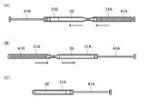
- FIG. 3 is a schematic view showing an example of the analysis chip of the present invention
- FIG. 3 is a cross-sectional view of the analysis chip 2
- FIG. 4 is a schematic view showing a part of the analysis chip 2 extracted.
- 4A and 4B are cross-sectional views showing a method of mixing the sample and the reagent using the analysis chip 2
- FIG. 4C shows a state where the analysis chip is separated. It is sectional drawing.
- the analysis chip 2 has a parallel flow path 3 and a pair of parallel pistons 4A and 4B.
- the parallel flow path 3 is configured by connecting a plurality of flow paths 31 to 36 in parallel.
- Each of the flow paths 31 to 36 includes a first syringe region and a second syringe region, and has a shape in which the tip of the first syringe region and the tip of the second syringe region are connected.
- the first syringe region side is referred to as a parallel region 3A on the first syringe region side
- the second syringe region side is referred to as a parallel region 3B on the second syringe region side.
- the first parallel piston 4A is inserted into the parallel region 3A on the first syringe region side, and the piston tip and the piston are arranged so as to correspond to the flow paths 31 to 36 in the parallel region 3A on the first syringe region side. It has pistons 41A to 46A connected to the support part, and further has a piston connecting part 47A for connecting the pistons 41A to 46A.
- the second parallel piston 4B is inserted into the parallel region 3B on the second syringe region side, and the piston tip and the piston are arranged so as to correspond to the flow paths 31 to 36 in the parallel region 3B on the second syringe region side.
- FIG. 3 shows a state in which the sample 50 is introduced into the parallel flow path 3 for convenience, the present invention is not limited to this.
- the shape of the flow paths 31 to 36 is not particularly limited, and the internal cross-sectional shape in the axial direction is, for example, a circle such as a perfect circle or an ellipse, or a square such as a square or a rectangle, and preferably a square.
- the size of the channels 31 to 36 is not particularly limited. In the flow paths 31 to 36, the tip of the syringe region is thinner than the other region of the syringe region (hereinafter referred to as “cylindrical region”).
- the size of the cylindrical region in the flow paths 31 to 36 is, for example, about 2 mm ⁇ 2 mm.
- a method of mixing a reagent and a sample using the analysis chip 2 will be described with reference to FIGS.
- the first parallel piston 4A or the second parallel piston 4B is removed from the analysis chip 2, and the sample 50 is introduced into each flow path in the parallel flow path 3.
- the removed parallel piston is inserted again into the processing position of the parallel flow path 3.
- the 1st parallel piston 4A and the 2nd parallel piston 4B are pushed alternately. Thereby, the sample 50 and the reagent in the parallel flow path 3 are mixed by moving between the first syringe region and the second syringe region.
- the second parallel piston 4B is pushed to the end, and the mixed solution 50 'of the sample and the reagent in the parallel flow path 3 is introduced into the parallel flow path 3A on the first syringe region side.
- the first parallel piston 4A is inserted at one end of each flow path.
- the tip piston is included.
- the piston support part and the piston connecting part 47A may be removed.
- the gap between the parallel flow path 3A on the first syringe area side where the reaction flow paths 31A are arranged and the parallel flow path on the second syringe area side where the flow paths 31B are arranged is cut.
- the parallel flow path 3A on the first syringe region side may be an analysis chip.
- tip 2 for analysis can be provided to the device for analysis of this invention as a reaction detection unit.
- the analysis chip 2 can be read as “reaction system preparation chip”, and the parallel flow path 3A on the first syringe region side removed from the reaction system preparation chip 2 is “analysis chip (or reaction detection)”. Unit) ”, and each flow path in the parallel flow path 3A on the first syringe region side can be read as a reaction flow path in the analysis chip.
- FIG. 5 An example of the analysis chip of the present invention thus obtained is shown in FIG. 5 and FIG.
- FIG. 5 is a schematic view showing an example of the analysis chip of the present invention.
- the analysis chip 3A has a plurality of reaction channels 31A to 36A connected in parallel.
- Each of the plurality of reaction flow paths 31A to 36A is closed at one end by the tip piston of the first parallel piston, and the other end is also closed.
- the shape and size of the reaction channels 31A to 36A are not particularly limited, and for example, the above-described examples can be used.
- the length of the reaction flow paths 31A to 36A in the axial direction is not particularly limited, and can be set according to, for example, a desired optical path length. Specific examples are 2 cm to 5 cm and 2.5 cm to 5 cm, for example.
- the analysis chip 3A may have a light shielding portion on the side surface adjacent to each other in the reaction channels 31A to 36A. Accordingly, it is possible to more effectively prevent the detection unit corresponding to each reaction channel from detecting a reaction in the adjacent reaction channel during the analysis by the analysis device.
- FIG. 7 is a schematic view showing a state in which the analysis chip 3A is set in the analysis device 1.
- FIG. 8 shows that after the analysis chip 3A is set in the analysis device 1, the light is emitted to the analysis chip 3A by the light source units 12a and 12b of the analysis device 1, and each reaction is performed by the detection unit 14 of the analysis device 1. It is the schematic which shows the state which detects the reaction in a flow path.
- FIG. 8 is a plan view showing a state in which the analysis chip 3A is set in the analysis device 1, but the upper surface of the analysis device 1 is omitted for easy understanding of the light irradiation state, and the analysis chip 3A is omitted. The upper surface of is shown in an exposed state.
- the analysis device 1 and the analysis chip 3A having the reaction system (reaction solution) in which the sample and the reagent are mixed are prepared. Then, as shown in FIGS. 7B and 7C, the analysis chip 3A is inserted into the analysis device 1 in the direction of the arrow in FIG.
- the analysis chip 3A is heated by the heating unit 13 of the analysis device 1, and the sample and the reagent are reacted in each of the reaction channels 31A to 36A.
- the reaction preferably includes, for example, a nucleic acid amplification reaction using a primer.
- the type of the nucleic acid amplification reaction is not particularly limited, and examples thereof include PCR method, TMA method, NASBA method, LAMP method, ICAN method, RCA method, SDA method, HDA method, SmartAmp method and the like. Among them, an isothermal amplification method such as the SmartAmp method is preferable because processing at a constant temperature is possible.
- linear light is irradiated in the direction of arrow A from the light source unit 12a to the analysis chip 3A set in the analysis device 1 shown in FIG. 8 (A).
- the line light from the light source unit 12a is converted into surface light, and is irradiated onto the parallel surface on the upper side of the analysis chip 3A as shown in FIG. 8C.
- a linear light is similarly irradiated from the light source part 12b, and the converted surface light is irradiated to the parallel surface below the analysis chip 3A.
- the plurality of detection units 14 respectively detect the reactions in the corresponding reaction flow paths indicated by arrows.
- the detection result by each detection unit 14 may be displayed on, for example, the analysis device 1 or displayed on an external display (for example, a personal computer, a mobile phone, a smartphone, a tablet, or the like) connected to the analysis device. You may let them.
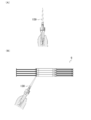
- FIG. 9 is a plan view showing an example of the analysis chip of the present invention.
- the analysis chip 9 includes a sample addition unit 9B and a reaction detection unit 9A configured from parallel flow paths, and a pair of parallel pistons 4B corresponding to the sample addition unit 9B and the reaction detection unit 9A. 4A.
- the sample addition unit 9B and the reaction detection unit 9A are in communication and integrated.
- the sample addition unit 9B has a sample insertion port 91 at one end of each flow path, and a primer as a reagent 92 is disposed inside the other end side.
- a transparent lens-shaped movable piece 95 is disposed inside each flow path.
- a line 93 is a line indicating the upper limit position of the amount of sample added from the sample insertion port 91
- a line 94 is a stop line when the parallel piston 4B is pushed into the sample addition unit 9B. .
- a dropper 100 having a nozzle is prepared.
- the pretreated specimen and a part of the amplification reagent for example, reaction buffer, enzyme
- the mixed sample is injected into the sample inlet 91 of the analysis chip 9 using the dropper 100.
- the mixed sample is injected up to the line 93 of the sample addition unit 9B in the analysis chip 9.
- the sample inlet 91 of the analysis chip 9 is closed with the seal 101, and then the parallel pistons 4A and 4B are alternately pushed, The mixed sample and the primer are further mixed to obtain a reaction solution.
- the movable piece 95 in the reaction detection unit 9A of the analysis chip 9 moves in conjunction with the parallel piston 4A.
- the parallel piston 4B is pushed to the line 94, and the parallel piston 4A is removed. At this time, the movable piece 95 stops at the end of the reaction detection unit 9A.
- reaction detection unit 9 A of the analysis chip 9 is inserted into the analysis device 1 having the USB connector 102. Then, the reaction detection unit 9A is heated by the analysis device 1 to perform the reaction, and the reaction is detected by a detection unit (not shown).
- the analysis device can be downsized. Further, according to the present invention, for example, an analyst prepares a reaction system by mixing a sample and a reagent in advance using the reaction system preparation chip of the present invention, and then prepares the reaction system.
- the target in the sample can be easily analyzed simply by separating the analytical chip of the present invention from the analytical chip and inserting it into the analytical device of the present invention. For this reason, simple analysis is possible also about viral infections, such as influenza virus, and sexually transmitted diseases, such as HIV and Chlamydia, for example.
- the analysis device can be downsized, for example, it is possible to easily perform an analysis by itself without going to an inspection organization such as a hospital.
Abstract
Description
分析用チップを挿入して、前記分析用チップにおけるサンプルと試薬との反応を分析するための分析用デバイスであり、
挿入される前記分析用チップは、
複数の反応流路が並列連結された並列流路を含み、
前記並列流路の軸方向が、前記分析用デバイスへの挿入方向であり、
前記分析用デバイスは、
本体ケース、加熱部、光源部、および複数の検出部を含み、
前記本体ケースは、
筐体であり、
前記分析用チップが挿入される、挿入口と前記挿入口に連通する空隙部とを有し、
前記加熱部は、
前記分析用チップ内のサンプルと試薬とを加熱反応させるための加熱部であり、
前記空隙部において、前記分析用チップが挿入された状態において前記分析用チップの前記並列流路の並列表面に対向するように、少なくとも一方の内部面に配置されており、
前記光源部は、
前記分析用チップに光照射するための光源部であり、
前記空隙部において、前記分析用チップが挿入された状態において前記分析用チップの前記並列流路の少なくとも一端の反応流路の上方および下方の少なくとも一方に位置し且つ前記並列流路の軸方向に沿うように、配置されており、
前記複数の検出部は、
前記分析用チップ内のサンプルと試薬との前記加熱反応を検出するための検出部であり、
それぞれ、前記空隙部において、前記分析用チップが挿入された状態において前記分析用チップの挿入方向の下流側端部であって且つ前記分析用チップの前記各反応流路に対応するように、配置されていることを特徴とする。
分析用デバイスに挿入される分析用チップであり、
前記分析用チップは、
複数の流路が並列連結された並列流路と、一対の並列ピストンと、試薬とを有し、
前記並列流路は、それぞれの流路が、内部に、試薬を有し、
前記流路は、それぞれ、
第1シリンジ領域と第2シリンジ領域とを含み、
前記第1シリンジ領域の先端と前記第2シリンジ領域の先端とが連結された形状であり、
前記第1シリンジ領域と前記第2シリンジ領域との連結部付近で切断可能であり、
前記一対の並列ピストンは、
第1並列ピストンと第2並列ピストンとを含み、
それぞれ、複数のピストンが並列連結されており、
前記第1並列ピストンは、それぞれのピストンが、前記並列流路の第1シリンジ領域の端部側から、前記各流路に挿入可能であり、
前記第2並列ピストンは、それぞれのピストンが、前記並列流路の第2シリンジ領域の端部側から、前記各流路に挿入可能であり、
前記サンプルと試薬との混合により反応系の調製を行った後、前記第1シリンジ領域側の並列流路を、反応検出ユニットとすることを特徴とする。
前記本発明の分析用チップにサンプルを導入する導入工程、
前記分析用チップにおいて、前記サンプルと試薬とを混合する混合工程、
前記分析用チップを、前記本発明の分析用デバイスに挿入する挿入工程、
前記分析用デバイスにおける加熱部により、前記分析用チップ内のサンプルと試薬とを加熱反応させる反応工程、および、
前記分析用デバイスにおける検出部により、前記分析用チップ内の前記反応を検出する検出工程を含むことを特徴とする。
本発明の分析用デバイスは、前述のように、
分析用チップを挿入して、前記分析用チップにおけるサンプルと試薬との反応を分析するための分析用デバイスであり、
挿入される前記分析用チップは、
複数の反応流路が並列連結された並列流路を含み、
前記並列流路の軸方向が、前記分析用デバイスへの挿入方向であり、
前記分析用デバイスは、
本体ケース、加熱部、光源部、および複数の検出部を含み、
前記本体ケースは、
筐体であり、
前記分析用チップが挿入される、挿入口と前記挿入口に連通する空隙部とを有し、
前記加熱部は、
前記分析用チップ内のサンプルと試薬とを加熱反応させるための加熱部であり、
前記空隙部において、前記分析用チップが挿入された状態において前記分析用チップの前記並列流路の並列表面に対向するように、少なくとも一方の内部面に配置されており、
前記光源部は、
前記分析用チップに光照射するための光源部であり、
前記空隙部において、前記分析用チップが挿入された状態において前記分析用チップの前記並列流路の少なくとも一端の反応流路の上方および下方の少なくとも一方に位置し且つ前記並列流路の軸方向に沿うように、配置されており、
前記複数の検出部は、
前記分析用チップ内のサンプルと試薬との前記加熱反応を検出するための検出部であり、
それぞれ、前記空隙部において、前記分析用チップが挿入された状態において前記分析用チップの挿入方向の下流側端部であって且つ前記分析用チップの前記各反応流路に対応するように、配置されていることを特徴とする。
本発明の分析用チップは、前述のように、分析用デバイスに挿入される分析用チップであり、
複数の反応流路が並列連結された並列流路を含むことを特徴とする。
本発明の分析用チップは、前述のように、
分析用デバイスに挿入される分析用チップであり、
前記分析用チップは、
複数の流路が並列連結された並列流路と、一対の並列ピストンと、試薬とを有し、
前記並列流路は、それぞれの流路が、内部に、試薬を有し、
前記流路は、それぞれ、
第1シリンジ領域と第2シリンジ領域とを含み、
前記第1シリンジ領域の先端と前記第2シリンジ領域の先端とが連結された形状であり、
前記第1シリンジ領域と前記第2シリンジ領域との連結部付近で切断可能であり、
前記一対の並列ピストンは、
第1並列ピストンと第2並列ピストンとを含み、
それぞれ、複数のピストンが並列連結されており、
前記第1並列ピストンは、それぞれのピストンが、前記並列流路の第1シリンジ領域の端部側から、前記各流路に挿入可能であり、
前記第2並列ピストンは、それぞれのピストンが、前記並列流路の第2シリンジ領域の端部側から、前記各流路に挿入可能であり、
前記サンプルと試薬との混合により反応系の調製を行った後、前記第1シリンジ領域側の並列流路を、反応検出ユニットとすることを特徴とする。
前記第1シリンジ領域側の並列流路および前記第2シリンジ領域側の並列流路のうち、一方が、試薬配置用の流路であり、他方が、サンプル導入用の流路である。本発明の分析用チップにおいて、いずれの領域側の並列流路が、前記試薬配置用の流路でも、前記サンプル導入用の流路でもよい。
本発明の分析キットは、前述のように、前記本発明の分析用デバイスと、前記本発明の分析用チップとを含むことを特徴とする。
本発明の分析方法は、前述のように、
前記本発明の分析用チップにサンプルを導入する導入工程、
前記分析用チップにおいて、前記サンプルと試薬とを混合する混合工程、
前記分析用チップを、前記本発明の分析用デバイスに挿入する挿入工程、
前記分析用デバイスにおける加熱部により、前記分析用チップ内のサンプルと試薬とを加熱反応させる反応工程、および、
前記分析用デバイスにおける検出部により、前記分析用チップ内の前記反応を検出する検出工程を含むことを特徴とする。
前記第1シリンジ領域側の並列流路の端部側から、前記第1並列ピストンを挿入し、
前記第2シリンジ領域側の並列流路の端部側から、サンプルを導入し、
前記サンプル導入後、前記第2シリンジ領域の並列流路の端部側から、前記第2並列ピストンを挿入する、
または、
前記第2シリンジ領域側の並列流路の端部側から、前記第2並列ピストンを挿入し、
前記第1シリンジ領域側の並列流路の端部側から、サンプルを導入し、
前記サンプル導入後、前記第1シリンジ領域の並列流路の端部側から、前記第1並列ピストンを挿入することが好ましい。
10 本体ケース
11 断熱部
12a、12b 光源部
13 加熱部
14 検出部
2、9 分析用チップ
9A 反応検出ユニット
9B 試料検出ユニット
91 サンプル投入口
92 試薬
93、94 ライン
95 可動駒
3 並列流路
3A 第1シリンジ領域側の並列流路(分析用チップまたは反応検出ユニット)
3B 第2シリンジ領域側の並列流路
31~36 流路
31A~36A 反応流路
31B 流路
4A、4B 並列ピストン
41A~46A、41B~46B ピストン
47A、47B 連結部
50 サンプル
50’ 混合液
61~65 遮光部
100 スポイト
101 シール
102 USBコネクタ
Claims (39)
- 分析用チップを挿入して、前記分析用チップにおけるサンプルと試薬との反応を分析するための分析用デバイスであり、
挿入される前記分析用チップは、
複数の反応流路が並列連結された並列流路を含み、
前記並列流路の軸方向が、前記分析用デバイスへの挿入方向であり、
前記分析用デバイスは、
本体ケース、加熱部、光源部、および複数の検出部を含み、
前記本体ケースは、
筐体であり、
前記分析用チップが挿入される、挿入口と前記挿入口に連通する空隙部とを有し、
前記加熱部は、
前記分析用チップ内のサンプルと試薬とを加熱反応させるための加熱部であり、
前記空隙部において、前記分析用チップが挿入された状態において前記分析用チップの前記並列流路の並列表面に対向するように、少なくとも一方の内部面に配置されており、
前記光源部は、
前記分析用チップに光照射するための光源部であり、
前記空隙部において、前記分析用チップが挿入された状態において前記分析用チップの前記並列流路の少なくとも一端の反応流路の上方および下方の少なくとも一方に位置し且つ前記並列流路の軸方向に沿うように、配置されており、
前記複数の検出部は、
前記分析用チップ内のサンプルと試薬との前記加熱反応を検出するための検出部であり、
それぞれ、前記空隙部において、前記分析用チップが挿入された状態において前記分析用チップの挿入方向の下流側端部であって且つ前記分析用チップの前記各反応流路に対応するように、配置されている
ことを特徴とする分析用デバイス。 - さらに、断熱部を有し、
前記本体ケースの空隙部において、前記断熱部を介して、前記加熱部が配置されている、請求項1記載の分析用デバイス。 - 前記光源部は、
線光源と、線光を面光に変換する変換器とを含み、
前記線光源により、前記反応流路の軸方向に沿って線光を照射し、
前記変換器により、前記線光を面光に変換して、面光を照射する、請求項1または2記載の分析用デバイス。 - 前記検出部が、CCDである、請求項1から3のいずれか一項に記載の分析用デバイス。
- 核酸分析用である、請求項1から4のいずれか一項に記載の分析用デバイス。
- さらに、電源、または外部電源とのコネクタを含む、請求項1から5のいずれか一項に記載の分析用デバイス。
- 前記外部電源が、パソコン、タブレット、または携帯電話である、請求項6記載の分析用デバイス。
- 分析用デバイスに挿入される分析用チップであり、
複数の反応流路が並列連結された並列流路を含む
ことを特徴とする分析用チップ。 - 前記並列流路の並列表面が、透光性であり、
前記並列流路は、それぞれの反応流路における隣の反応流路に接する側面が、遮光性である、請求項8記載の分析用チップ。 - 前記並列流路は、
それぞれの反応流路の両末端の開口を閉口可能である、請求項8または9記載の分析用チップ。 - 前記並列流路は、
それぞれの反応流路が、内部に、集光レンズを含む、請求項8から10のいずれか一項に記載の分析用チップ。 - 前記並列流路は、
それぞれの反応流路が、内部に、試薬を有する、請求項8から11のいずれか一項に記載の分析用チップ。 - 前記試薬が、サンプル中のターゲットと反応する分析用試薬を含む、請求項8から12のいずれか一項に記載の分析用チップ。
- 前記並列流路における2つ以上の反応流路が、それぞれ、サンプル中の異なるターゲットと反応する分析用試薬を含む、請求項13記載の分析用チップ。
- 前記ターゲットが、核酸であり、
前記分析用試薬が、核酸増幅用試薬を含む、請求項13または14記載の分析用チップ。 - 前記ターゲットが核酸であり、
前記試薬が、核酸検出用試薬を含む、請求項13から15のいずれか一項に記載の分析用チップ。 - 前記核酸検出用試薬が、蛍光試薬である、請求項16記載の分析用チップ。
- 前記試薬が、サンプルの前処理試薬を含む、請求項8から17のいずれか一項に記載の分析用チップ。
- 分析用デバイスに挿入される分析用チップであり、
前記分析用チップは、
複数の流路が並列連結された並列流路と、一対の並列ピストンと、試薬とを有し、
前記並列流路は、それぞれの流路が、内部に、試薬を有し、
前記流路は、それぞれ、
第1シリンジ領域と第2シリンジ領域とを含み、
前記第1シリンジ領域の先端と前記第2シリンジ領域の先端とが連結された形状であり、
前記第1シリンジ領域と前記第2シリンジ領域との連結部付近で切断可能であり、
前記一対の並列ピストンは、
第1並列ピストンと第2並列ピストンとを含み、
それぞれ、複数のピストンが並列連結されており、
前記第1並列ピストンは、それぞれのピストンが、前記並列流路の第1シリンジ領域の端部側から、前記各流路に挿入可能であり、
前記第2並列ピストンは、それぞれのピストンが、前記並列流路の第2シリンジ領域の端部側から、前記各流路に挿入可能であり、
前記サンプルと試薬との混合により反応系の調製を行った後、前記第1シリンジ領域側の並列流路を、反応検出ユニットとすることを特徴とする分析用チップ。 - 前記複数の流路が並列連結された並列流路において、
前記第1シリンジ領域側の並列流路および前記第2シリンジ領域側の並列流路のうち、
一方が、試薬配置用の流路であり、他方が、サンプル導入用の流路である、請求項19記載の分析用チップ。 - 前記反応検出ユニットになる前記第1シリンジ領域側の並列流路は、
その並列表面が、透過性であり、
それぞれの流路における隣の流路に接する側面が、遮光性である、
請求項19または20記載の分析用チップ。 - 前記サンプルと試薬との混合により反応系の調製を行った後、前記並列流路を並列方向に切断することで、前記第1シリンジ領域側の並列流路を、反応検出ユニットとする、請求項19から21のいずれか一項に記載の分析用チップ。
- 前記反応検出ユニットになる前記第1シリンジ領域側の並列流路は、その内部に、集光レンズを含む、請求項19から22のいずれか一項に記載の分析用チップ。
- 前記試薬が、サンプルの前処理試薬を含む、請求項19から23のいずれか一項に記載の分析用チップ。
- 前記試薬が、サンプル中のターゲットと反応する分析用試薬を含む、請求項19から24のいずれか一項に記載の分析用チップ。
- 前記並列流路における2つ以上の流路が、それぞれ、前記サンプル中の異なるターゲットと反応する分析用試薬を含む、請求項25記載の分析用チップ。
- 前記ターゲットが、核酸であり、
前記分析用試薬が、核酸増幅用試薬を含む、請求項25または26記載の分析用チップ。 - 前記ターゲットが、核酸であり、
前記分析用試薬が、核酸検出用試薬を含む、請求項25から27のいずれか一項に記載の分析用チップ。 - 前記核酸検出用試薬が、蛍光試薬である、請求項28記載の分析用チップ。
- 前記第1シリンジ領域側の並列流路に挿入される前記第1並列ピストンは、
それぞれのピストンが、光ファイバーを含む、請求項19から29のいずれか一項に記載の分析用チップ。 - 請求項1から7のいずれか一項に記載の分析用デバイスと、
請求項8から30のいずれか一項に記載の分析用チップとを含むことを特徴とする分析キット。 - 請求項8から30のいずれか一項に記載の分析用チップにサンプルを導入する導入工程、
前記分析用チップにおいて、前記サンプルと試薬とを混合する混合工程、
前記分析用チップを、請求項1から7のいずれか一項に記載の分析用デバイスに挿入する挿入工程、
前記分析用デバイスにおける加熱部により、前記分析用チップ内のサンプルと試薬とを加熱反応させる反応工程、および、
前記分析用デバイスにおける検出部により、前記分析用チップ内の前記反応を検出する検出工程を含むことを特徴とするサンプルの分析方法。 - 前記導入工程において、
前記第1シリンジ領域側の並列流路の端部側から、前記第1並列ピストンを挿入し、
前記第2シリンジ領域側の並列流路の端部側から、サンプルを導入し、
前記サンプル導入後、前記第2シリンジ領域の並列流路の端部側から、前記第2並列ピストンを挿入する、
または、
前記第2シリンジ領域側の並列流路の端部側から、前記第2並列ピストンを挿入し、
前記第1シリンジ領域側の並列流路の端部側から、サンプルを導入し、
前記サンプル導入後、前記第1シリンジ領域の並列流路の端部側から、前記第1並列ピストンを挿入する、請求項32記載の分析方法。 - 前記第1並列ピストンと前記第2並列ピストンとを、交互に押すことで、前記並列流路の各流路内において、前記サンプルと前記試薬とを混合する、請求項32または33記載の分析方法。
- 前記混合工程後、前記挿入工程前において、請求項19から30のいずれか一項に記載の分析チップについて、前記並列流路を並列方向に切断することで、前記第1シリンジ領域側の並列流路を、反応検出ユニットとして分離し、前記反応検出ユニットを前記分析用チップとして前記分析用デバイスに挿入する、請求項32から34のいずれか一項に記載の分析方法。
- 分析対象が、核酸である、請求項32から35のいずれか一項に記載の分析方法。
- サンプルが、生体試料である、請求項32から36のいずれか一項に記載の分析方法。
- 前記生体試料が、血液、血漿および血清からなる群から選択された少なくとも一つである、請求項37記載の分析方法。
- 分析ターゲットが、ウイルスまたはバクテリアである、請求項32から38のいずれか一項に記載の分析方法。
Priority Applications (4)
| Application Number | Priority Date | Filing Date | Title |
|---|---|---|---|
| US15/314,373 US20170197216A1 (en) | 2015-01-28 | 2016-01-28 | Analysis device, analysis chip, analysis kit, and analysis method using same |
| RU2016151351A RU2016151351A (ru) | 2015-01-28 | 2016-01-28 | Устройство для анализа, чип для анализа, набор для анализа и способ анализа с их применением |
| EP16743489.3A EP3144380A4 (en) | 2015-01-28 | 2016-01-28 | Analysis device, analysis chip, analysis kit, and analysis method using same |
| JP2016572154A JPWO2016121886A1 (ja) | 2015-01-28 | 2016-01-28 | 分析用デバイス、分析用チップ、分析キット、および、これらを用いた分析方法 |
Applications Claiming Priority (2)
| Application Number | Priority Date | Filing Date | Title |
|---|---|---|---|
| JP2015014849 | 2015-01-28 | ||
| JP2015-014849 | 2015-01-28 |
Publications (1)
| Publication Number | Publication Date |
|---|---|
| WO2016121886A1 true WO2016121886A1 (ja) | 2016-08-04 |
Family
ID=56543491
Family Applications (1)
| Application Number | Title | Priority Date | Filing Date |
|---|---|---|---|
| PCT/JP2016/052530 WO2016121886A1 (ja) | 2015-01-28 | 2016-01-28 | 分析用デバイス、分析用チップ、分析キット、および、これらを用いた分析方法 |
Country Status (5)
| Country | Link |
|---|---|
| US (1) | US20170197216A1 (ja) |
| EP (1) | EP3144380A4 (ja) |
| JP (1) | JPWO2016121886A1 (ja) |
| RU (1) | RU2016151351A (ja) |
| WO (1) | WO2016121886A1 (ja) |
Cited By (3)
| Publication number | Priority date | Publication date | Assignee | Title |
|---|---|---|---|---|
| JP2018028437A (ja) * | 2016-08-15 | 2018-02-22 | 住友ゴム工業株式会社 | マイクロ流路チップ |
| WO2018135572A1 (ja) * | 2017-01-18 | 2018-07-26 | 伸晃化学株式会社 | 化学物質評価用のデバイス、および、化学物質評価方法 |
| JP2019533804A (ja) * | 2016-09-09 | 2019-11-21 | インビトロン リミテッド | ポイントオブケア検査用の装置プラットフォーム |
Citations (14)
| Publication number | Priority date | Publication date | Assignee | Title |
|---|---|---|---|---|
| JP2004208512A (ja) * | 2002-12-27 | 2004-07-29 | Asahi Kasei Corp | 核酸検出用カートリッジ |
| JP2004305009A (ja) * | 2003-04-02 | 2004-11-04 | Hitachi Ltd | 核酸増幅装置及び核酸増幅方法 |
| JP2007516419A (ja) * | 2003-07-04 | 2007-06-21 | マグニセンス・リミテッド | マルチマイクロチューブアレーの形態のモノリシックチャンバーと積分測定用ラテラルトランスデューサーを備えるセンサーによる化学的又は生物学的分析方法及び装置 |
| JP2007248290A (ja) * | 2006-03-16 | 2007-09-27 | Nippon Telegr & Teleph Corp <Ntt> | マイクロ流路素子 |
| JP2008148690A (ja) * | 2006-11-22 | 2008-07-03 | Fujifilm Corp | マイクロチップを用いた核酸増幅方法およびマイクロチップ、それを用いた核酸増幅システム |
| WO2008123112A1 (ja) * | 2007-03-23 | 2008-10-16 | Kabushiki Kaisha Toshiba | 核酸検出カセット及び核酸検出装置 |
| JP2009503555A (ja) * | 2005-08-04 | 2009-01-29 | ヘリコス バイオサイエンシーズ コーポレイション | マルチチャネルフローセル |
| JP2009268432A (ja) * | 2008-05-09 | 2009-11-19 | Canon Inc | 標的核酸の測定方法 |
| WO2009157327A1 (ja) * | 2008-06-23 | 2009-12-30 | 株式会社 日立ハイテクノロジーズ | 単分子リアルタイムシーケンス装置,核酸分析装置及び単分子リアルタイムシーケンス方法 |
| JP2011501965A (ja) * | 2007-10-30 | 2011-01-20 | コンプリート・ゲノミックス・インコーポレーテッド | 核酸のハイ・スループット塩基配列決定のための装置 |
| JP2012503773A (ja) * | 2008-09-23 | 2012-02-09 | クァンタライフ・インコーポレーテッド | 液滴ベースの分析システム |
| JP2012085659A (ja) * | 2004-05-02 | 2012-05-10 | Fluidigm Corp | 熱反応デバイスおよびその熱反応デバイスの使用方法 |
| JP2012516455A (ja) * | 2009-01-30 | 2012-07-19 | マイクロニクス, インコーポレイテッド | 携帯型高利得蛍光検出システム |
| JP2014194378A (ja) * | 2013-03-29 | 2014-10-09 | Hitachi High-Technologies Corp | 核酸分析装置 |
Family Cites Families (6)
| Publication number | Priority date | Publication date | Assignee | Title |
|---|---|---|---|---|
| US6977145B2 (en) * | 1999-07-28 | 2005-12-20 | Serono Genetics Institute S.A. | Method for carrying out a biochemical protocol in continuous flow in a microreactor |
| EP1887363A4 (en) * | 2005-04-01 | 2012-08-22 | Konica Minolta Med & Graphic | MICRO-TOTAL ANALYSIS SYSTEM, INSPECTION SCHIP AND INSPECTION PROCESS |
| WO2008005241A2 (en) * | 2006-06-30 | 2008-01-10 | Canon U.S. Life Sciences, Inc. | Systems and methods for monitoring the amplification and dissociation behavior of dna molecules |
| US8105783B2 (en) * | 2007-07-13 | 2012-01-31 | Handylab, Inc. | Microfluidic cartridge |
| EA023941B1 (ru) * | 2010-04-16 | 2016-07-29 | Опкоу Дайагностикс, Ллк. | Анализатор микрофлюидного образца и способ выполнения анализа микрофлюидного образца |
| US20110312739A1 (en) * | 2010-06-17 | 2011-12-22 | Geneasys Pty Ltd | Single-use test module for pcr amplification of targets and electrochemiluminescent detection of targets |
-
2016
- 2016-01-28 JP JP2016572154A patent/JPWO2016121886A1/ja not_active Withdrawn
- 2016-01-28 US US15/314,373 patent/US20170197216A1/en not_active Abandoned
- 2016-01-28 RU RU2016151351A patent/RU2016151351A/ru not_active Application Discontinuation
- 2016-01-28 EP EP16743489.3A patent/EP3144380A4/en not_active Withdrawn
- 2016-01-28 WO PCT/JP2016/052530 patent/WO2016121886A1/ja active Application Filing
Patent Citations (14)
| Publication number | Priority date | Publication date | Assignee | Title |
|---|---|---|---|---|
| JP2004208512A (ja) * | 2002-12-27 | 2004-07-29 | Asahi Kasei Corp | 核酸検出用カートリッジ |
| JP2004305009A (ja) * | 2003-04-02 | 2004-11-04 | Hitachi Ltd | 核酸増幅装置及び核酸増幅方法 |
| JP2007516419A (ja) * | 2003-07-04 | 2007-06-21 | マグニセンス・リミテッド | マルチマイクロチューブアレーの形態のモノリシックチャンバーと積分測定用ラテラルトランスデューサーを備えるセンサーによる化学的又は生物学的分析方法及び装置 |
| JP2012085659A (ja) * | 2004-05-02 | 2012-05-10 | Fluidigm Corp | 熱反応デバイスおよびその熱反応デバイスの使用方法 |
| JP2009503555A (ja) * | 2005-08-04 | 2009-01-29 | ヘリコス バイオサイエンシーズ コーポレイション | マルチチャネルフローセル |
| JP2007248290A (ja) * | 2006-03-16 | 2007-09-27 | Nippon Telegr & Teleph Corp <Ntt> | マイクロ流路素子 |
| JP2008148690A (ja) * | 2006-11-22 | 2008-07-03 | Fujifilm Corp | マイクロチップを用いた核酸増幅方法およびマイクロチップ、それを用いた核酸増幅システム |
| WO2008123112A1 (ja) * | 2007-03-23 | 2008-10-16 | Kabushiki Kaisha Toshiba | 核酸検出カセット及び核酸検出装置 |
| JP2011501965A (ja) * | 2007-10-30 | 2011-01-20 | コンプリート・ゲノミックス・インコーポレーテッド | 核酸のハイ・スループット塩基配列決定のための装置 |
| JP2009268432A (ja) * | 2008-05-09 | 2009-11-19 | Canon Inc | 標的核酸の測定方法 |
| WO2009157327A1 (ja) * | 2008-06-23 | 2009-12-30 | 株式会社 日立ハイテクノロジーズ | 単分子リアルタイムシーケンス装置,核酸分析装置及び単分子リアルタイムシーケンス方法 |
| JP2012503773A (ja) * | 2008-09-23 | 2012-02-09 | クァンタライフ・インコーポレーテッド | 液滴ベースの分析システム |
| JP2012516455A (ja) * | 2009-01-30 | 2012-07-19 | マイクロニクス, インコーポレイテッド | 携帯型高利得蛍光検出システム |
| JP2014194378A (ja) * | 2013-03-29 | 2014-10-09 | Hitachi High-Technologies Corp | 核酸分析装置 |
Non-Patent Citations (1)
| Title |
|---|
| See also references of EP3144380A4 * |
Cited By (6)
| Publication number | Priority date | Publication date | Assignee | Title |
|---|---|---|---|---|
| JP2018028437A (ja) * | 2016-08-15 | 2018-02-22 | 住友ゴム工業株式会社 | マイクロ流路チップ |
| US10799866B2 (en) | 2016-08-15 | 2020-10-13 | Sumitomo Rubber Industries, Ltd. | Microfluidic chip |
| JP2019533804A (ja) * | 2016-09-09 | 2019-11-21 | インビトロン リミテッド | ポイントオブケア検査用の装置プラットフォーム |
| WO2018135572A1 (ja) * | 2017-01-18 | 2018-07-26 | 伸晃化学株式会社 | 化学物質評価用のデバイス、および、化学物質評価方法 |
| JPWO2018135572A1 (ja) * | 2017-01-18 | 2019-11-07 | 伸晃化学株式会社 | 化学物質評価用のデバイス、および、化学物質評価方法 |
| JP7251725B2 (ja) | 2017-01-18 | 2023-04-04 | 伸晃化学株式会社 | 化学物質評価用のデバイス、および、化学物質評価方法 |
Also Published As
| Publication number | Publication date |
|---|---|
| EP3144380A1 (en) | 2017-03-22 |
| RU2016151351A (ru) | 2019-02-28 |
| US20170197216A1 (en) | 2017-07-13 |
| EP3144380A4 (en) | 2018-04-25 |
| RU2016151351A3 (ja) | 2019-06-11 |
| JPWO2016121886A1 (ja) | 2017-11-02 |
Similar Documents
| Publication | Publication Date | Title |
|---|---|---|
| EP3150690B1 (en) | Instrument for the manipulation of cartridges to perform nucleic acid isolation and amplification processes | |
| KR102059004B1 (ko) | 통합형 전달 모듈을 구비한 테스트 카트리지 | |
| US20090061450A1 (en) | System and method for diagnosis of infectious diseases | |
| US10252264B2 (en) | Sample preparation module with stepwise pressurization mechanism | |
| BRPI0717552A2 (pt) | Sistema de cartucho, método para formar um cartucho, cartucho, sistema de ensaio, método de análise para um ou mais analitos em uma amostra, componente de reagente para armazenar um ou mais reagentes, e, uso de um sistema de cartucho, cartucho, sistema de ensaio e/ou componente de reagente | |
| KR20170024827A (ko) | 미세유로 필름 반응기, 핵산 추출 모듈 및 qPCR 반응조성물 모듈이 구비된 qPCR 카트리지 및 이를 이용한 고속 qPCR 시스템 | |
| AU2007225103A1 (en) | System and method for diagnosis of infectious diseases | |
| WO2012151473A2 (en) | Apparatus and methods for integrated sample preparation, reaction and detection | |
| WO2017018014A1 (ja) | 分析用キット、および、これを用いた分析方法 | |
| WO2016121886A1 (ja) | 分析用デバイス、分析用チップ、分析キット、および、これらを用いた分析方法 | |
| CN104946505A (zh) | 实现pcr的微流控芯片及实时pcr的病毒快速检测装置 | |
| AU2014224115B2 (en) | Apparatus and methods for integrated sample preparation, reaction and detection | |
| CN109797204A (zh) | 一种基于圆盘状毛细管微阵列的多重核酸检测方法 | |
| KR20230156575A (ko) | 샘플 필터링이 가능한 타깃 분석물 검출 카트리지 | |
| KR20240045180A (ko) | 검출챔버를 포함하는 타깃 분석물 검출 카트리지 | |
| KR20240045179A (ko) | 챔버 밀폐가 가능한 타깃 분석물 검출 카트리지 | |
| RU2800583C2 (ru) | Система для полимеразной цепной реакции | |
| KR20230156574A (ko) | 커버를 포함하는 타깃 분석물 검출 카트리지 | |
| US20230256432A1 (en) | Nucleic acid extraction container and nucleic acid extraction method | |
| KR20240053619A (ko) | 샘플 테스트를 위해 밀봉부를 피어싱하는 방법 | |
| CN116802476A (zh) | 即时微流体体外诊断系统 | |
| KR20230140525A (ko) | 타깃 분석물 검출 카트리지 | |
| AU2015221472B2 (en) | Apparatus and methods for integrated sample preparation, reaction and detection | |
| Georgieva et al. | РOINT-OF-CARE DIAGNOSIS OF INFECTIOUS DISEASES BY VARIOUS LABORATORY DEVICES AND SYSTEMS | |
| WO2023034995A1 (en) | Method of piercing seal for sample testing |
Legal Events
| Date | Code | Title | Description |
|---|---|---|---|
| 121 | Ep: the epo has been informed by wipo that ep was designated in this application |
Ref document number: 16743489 Country of ref document: EP Kind code of ref document: A1 |
|
| ENP | Entry into the national phase |
Ref document number: 2016572154 Country of ref document: JP Kind code of ref document: A |
|
| WWE | Wipo information: entry into national phase |
Ref document number: 15314373 Country of ref document: US |
|
| REEP | Request for entry into the european phase |
Ref document number: 2016743489 Country of ref document: EP |
|
| WWE | Wipo information: entry into national phase |
Ref document number: 2016743489 Country of ref document: EP |
|
| NENP | Non-entry into the national phase |
Ref country code: DE |
|
| ENP | Entry into the national phase |
Ref document number: 2016151351 Country of ref document: RU Kind code of ref document: A |