WO2016121856A1 - 複層フィルム、その用途、及び製造方法 - Google Patents
複層フィルム、その用途、及び製造方法 Download PDFInfo
- Publication number
- WO2016121856A1 WO2016121856A1 PCT/JP2016/052456 JP2016052456W WO2016121856A1 WO 2016121856 A1 WO2016121856 A1 WO 2016121856A1 JP 2016052456 W JP2016052456 W JP 2016052456W WO 2016121856 A1 WO2016121856 A1 WO 2016121856A1
- Authority
- WO
- WIPO (PCT)
- Prior art keywords
- group
- liquid crystal
- carbon atoms
- optically anisotropic
- anisotropic layer
- Prior art date
- Legal status (The legal status is an assumption and is not a legal conclusion. Google has not performed a legal analysis and makes no representation as to the accuracy of the status listed.)
- Ceased
Links
Images

Classifications
-
- G—PHYSICS
- G02—OPTICS
- G02B—OPTICAL ELEMENTS, SYSTEMS OR APPARATUS
- G02B5/00—Optical elements other than lenses
- G02B5/30—Polarising elements
- G02B5/3016—Polarising elements involving passive liquid crystal elements
-
- G—PHYSICS
- G02—OPTICS
- G02B—OPTICAL ELEMENTS, SYSTEMS OR APPARATUS
- G02B5/00—Optical elements other than lenses
- G02B5/30—Polarising elements
- G02B5/3083—Birefringent or phase retarding elements
-
- G—PHYSICS
- G02—OPTICS
- G02F—OPTICAL DEVICES OR ARRANGEMENTS FOR THE CONTROL OF LIGHT BY MODIFICATION OF THE OPTICAL PROPERTIES OF THE MEDIA OF THE ELEMENTS INVOLVED THEREIN; NON-LINEAR OPTICS; FREQUENCY-CHANGING OF LIGHT; OPTICAL LOGIC ELEMENTS; OPTICAL ANALOGUE/DIGITAL CONVERTERS
- G02F1/00—Devices or arrangements for the control of the intensity, colour, phase, polarisation or direction of light arriving from an independent light source, e.g. switching, gating or modulating; Non-linear optics
- G02F1/01—Devices or arrangements for the control of the intensity, colour, phase, polarisation or direction of light arriving from an independent light source, e.g. switching, gating or modulating; Non-linear optics for the control of the intensity, phase, polarisation or colour
- G02F1/13—Devices or arrangements for the control of the intensity, colour, phase, polarisation or direction of light arriving from an independent light source, e.g. switching, gating or modulating; Non-linear optics for the control of the intensity, phase, polarisation or colour based on liquid crystals, e.g. single liquid crystal display cells
- G02F1/133—Constructional arrangements; Operation of liquid crystal cells; Circuit arrangements
- G02F1/1333—Constructional arrangements; Manufacturing methods
- G02F1/1335—Structural association of cells with optical devices, e.g. polarisers or reflectors
- G02F1/133528—Polarisers
-
- G—PHYSICS
- G02—OPTICS
- G02F—OPTICAL DEVICES OR ARRANGEMENTS FOR THE CONTROL OF LIGHT BY MODIFICATION OF THE OPTICAL PROPERTIES OF THE MEDIA OF THE ELEMENTS INVOLVED THEREIN; NON-LINEAR OPTICS; FREQUENCY-CHANGING OF LIGHT; OPTICAL LOGIC ELEMENTS; OPTICAL ANALOGUE/DIGITAL CONVERTERS
- G02F1/00—Devices or arrangements for the control of the intensity, colour, phase, polarisation or direction of light arriving from an independent light source, e.g. switching, gating or modulating; Non-linear optics
- G02F1/01—Devices or arrangements for the control of the intensity, colour, phase, polarisation or direction of light arriving from an independent light source, e.g. switching, gating or modulating; Non-linear optics for the control of the intensity, phase, polarisation or colour
- G02F1/13—Devices or arrangements for the control of the intensity, colour, phase, polarisation or direction of light arriving from an independent light source, e.g. switching, gating or modulating; Non-linear optics for the control of the intensity, phase, polarisation or colour based on liquid crystals, e.g. single liquid crystal display cells
- G02F1/133—Constructional arrangements; Operation of liquid crystal cells; Circuit arrangements
- G02F1/1333—Constructional arrangements; Manufacturing methods
- G02F1/1335—Structural association of cells with optical devices, e.g. polarisers or reflectors
- G02F1/13363—Birefringent elements, e.g. for optical compensation
-
- G—PHYSICS
- G02—OPTICS
- G02F—OPTICAL DEVICES OR ARRANGEMENTS FOR THE CONTROL OF LIGHT BY MODIFICATION OF THE OPTICAL PROPERTIES OF THE MEDIA OF THE ELEMENTS INVOLVED THEREIN; NON-LINEAR OPTICS; FREQUENCY-CHANGING OF LIGHT; OPTICAL LOGIC ELEMENTS; OPTICAL ANALOGUE/DIGITAL CONVERTERS
- G02F1/00—Devices or arrangements for the control of the intensity, colour, phase, polarisation or direction of light arriving from an independent light source, e.g. switching, gating or modulating; Non-linear optics
- G02F1/01—Devices or arrangements for the control of the intensity, colour, phase, polarisation or direction of light arriving from an independent light source, e.g. switching, gating or modulating; Non-linear optics for the control of the intensity, phase, polarisation or colour
- G02F1/13—Devices or arrangements for the control of the intensity, colour, phase, polarisation or direction of light arriving from an independent light source, e.g. switching, gating or modulating; Non-linear optics for the control of the intensity, phase, polarisation or colour based on liquid crystals, e.g. single liquid crystal display cells
- G02F1/133—Constructional arrangements; Operation of liquid crystal cells; Circuit arrangements
- G02F1/1333—Constructional arrangements; Manufacturing methods
- G02F1/1335—Structural association of cells with optical devices, e.g. polarisers or reflectors
- G02F1/13363—Birefringent elements, e.g. for optical compensation
- G02F1/133633—Birefringent elements, e.g. for optical compensation using mesogenic materials
-
- G—PHYSICS
- G02—OPTICS
- G02F—OPTICAL DEVICES OR ARRANGEMENTS FOR THE CONTROL OF LIGHT BY MODIFICATION OF THE OPTICAL PROPERTIES OF THE MEDIA OF THE ELEMENTS INVOLVED THEREIN; NON-LINEAR OPTICS; FREQUENCY-CHANGING OF LIGHT; OPTICAL LOGIC ELEMENTS; OPTICAL ANALOGUE/DIGITAL CONVERTERS
- G02F1/00—Devices or arrangements for the control of the intensity, colour, phase, polarisation or direction of light arriving from an independent light source, e.g. switching, gating or modulating; Non-linear optics
- G02F1/01—Devices or arrangements for the control of the intensity, colour, phase, polarisation or direction of light arriving from an independent light source, e.g. switching, gating or modulating; Non-linear optics for the control of the intensity, phase, polarisation or colour
- G02F1/13—Devices or arrangements for the control of the intensity, colour, phase, polarisation or direction of light arriving from an independent light source, e.g. switching, gating or modulating; Non-linear optics for the control of the intensity, phase, polarisation or colour based on liquid crystals, e.g. single liquid crystal display cells
- G02F1/133—Constructional arrangements; Operation of liquid crystal cells; Circuit arrangements
- G02F1/1333—Constructional arrangements; Manufacturing methods
- G02F1/1335—Structural association of cells with optical devices, e.g. polarisers or reflectors
- G02F1/13363—Birefringent elements, e.g. for optical compensation
- G02F1/133638—Waveplates, i.e. plates with a retardation value of lambda/n
-
- G—PHYSICS
- G02—OPTICS
- G02F—OPTICAL DEVICES OR ARRANGEMENTS FOR THE CONTROL OF LIGHT BY MODIFICATION OF THE OPTICAL PROPERTIES OF THE MEDIA OF THE ELEMENTS INVOLVED THEREIN; NON-LINEAR OPTICS; FREQUENCY-CHANGING OF LIGHT; OPTICAL LOGIC ELEMENTS; OPTICAL ANALOGUE/DIGITAL CONVERTERS
- G02F1/00—Devices or arrangements for the control of the intensity, colour, phase, polarisation or direction of light arriving from an independent light source, e.g. switching, gating or modulating; Non-linear optics
- G02F1/01—Devices or arrangements for the control of the intensity, colour, phase, polarisation or direction of light arriving from an independent light source, e.g. switching, gating or modulating; Non-linear optics for the control of the intensity, phase, polarisation or colour
- G02F1/13—Devices or arrangements for the control of the intensity, colour, phase, polarisation or direction of light arriving from an independent light source, e.g. switching, gating or modulating; Non-linear optics for the control of the intensity, phase, polarisation or colour based on liquid crystals, e.g. single liquid crystal display cells
- G02F1/133—Constructional arrangements; Operation of liquid crystal cells; Circuit arrangements
- G02F1/1333—Constructional arrangements; Manufacturing methods
- G02F1/1337—Surface-induced orientation of the liquid crystal molecules, e.g. by alignment layers
-
- H—ELECTRICITY
- H05—ELECTRIC TECHNIQUES NOT OTHERWISE PROVIDED FOR
- H05B—ELECTRIC HEATING; ELECTRIC LIGHT SOURCES NOT OTHERWISE PROVIDED FOR; CIRCUIT ARRANGEMENTS FOR ELECTRIC LIGHT SOURCES, IN GENERAL
- H05B33/00—Electroluminescent light sources
- H05B33/02—Details
-
- H—ELECTRICITY
- H10—SEMICONDUCTOR DEVICES; ELECTRIC SOLID-STATE DEVICES NOT OTHERWISE PROVIDED FOR
- H10K—ORGANIC ELECTRIC SOLID-STATE DEVICES
- H10K50/00—Organic light-emitting devices
- H10K50/10—OLEDs or polymer light-emitting diodes [PLED]
- H10K50/11—OLEDs or polymer light-emitting diodes [PLED] characterised by the electroluminescent [EL] layers
-
- H—ELECTRICITY
- H10—SEMICONDUCTOR DEVICES; ELECTRIC SOLID-STATE DEVICES NOT OTHERWISE PROVIDED FOR
- H10K—ORGANIC ELECTRIC SOLID-STATE DEVICES
- H10K50/00—Organic light-emitting devices
- H10K50/80—Constructional details
- H10K50/868—Arrangements for polarized light emission
-
- H—ELECTRICITY
- H10—SEMICONDUCTOR DEVICES; ELECTRIC SOLID-STATE DEVICES NOT OTHERWISE PROVIDED FOR
- H10K—ORGANIC ELECTRIC SOLID-STATE DEVICES
- H10K59/00—Integrated devices, or assemblies of multiple devices, comprising at least one organic light-emitting element covered by group H10K50/00
- H10K59/80—Constructional details
- H10K59/8791—Arrangements for improving contrast, e.g. preventing reflection of ambient light
-
- H—ELECTRICITY
- H10—SEMICONDUCTOR DEVICES; ELECTRIC SOLID-STATE DEVICES NOT OTHERWISE PROVIDED FOR
- H10K—ORGANIC ELECTRIC SOLID-STATE DEVICES
- H10K59/00—Integrated devices, or assemblies of multiple devices, comprising at least one organic light-emitting element covered by group H10K50/00
- H10K59/80—Constructional details
- H10K59/8793—Arrangements for polarized light emission
-
- G—PHYSICS
- G02—OPTICS
- G02F—OPTICAL DEVICES OR ARRANGEMENTS FOR THE CONTROL OF LIGHT BY MODIFICATION OF THE OPTICAL PROPERTIES OF THE MEDIA OF THE ELEMENTS INVOLVED THEREIN; NON-LINEAR OPTICS; FREQUENCY-CHANGING OF LIGHT; OPTICAL LOGIC ELEMENTS; OPTICAL ANALOGUE/DIGITAL CONVERTERS
- G02F1/00—Devices or arrangements for the control of the intensity, colour, phase, polarisation or direction of light arriving from an independent light source, e.g. switching, gating or modulating; Non-linear optics
- G02F1/01—Devices or arrangements for the control of the intensity, colour, phase, polarisation or direction of light arriving from an independent light source, e.g. switching, gating or modulating; Non-linear optics for the control of the intensity, phase, polarisation or colour
- G02F1/13—Devices or arrangements for the control of the intensity, colour, phase, polarisation or direction of light arriving from an independent light source, e.g. switching, gating or modulating; Non-linear optics for the control of the intensity, phase, polarisation or colour based on liquid crystals, e.g. single liquid crystal display cells
- G02F1/133—Constructional arrangements; Operation of liquid crystal cells; Circuit arrangements
- G02F1/1333—Constructional arrangements; Manufacturing methods
- G02F1/1335—Structural association of cells with optical devices, e.g. polarisers or reflectors
- G02F1/133528—Polarisers
- G02F1/133541—Circular polarisers
-
- G—PHYSICS
- G02—OPTICS
- G02F—OPTICAL DEVICES OR ARRANGEMENTS FOR THE CONTROL OF LIGHT BY MODIFICATION OF THE OPTICAL PROPERTIES OF THE MEDIA OF THE ELEMENTS INVOLVED THEREIN; NON-LINEAR OPTICS; FREQUENCY-CHANGING OF LIGHT; OPTICAL LOGIC ELEMENTS; OPTICAL ANALOGUE/DIGITAL CONVERTERS
- G02F2413/00—Indexing scheme related to G02F1/13363, i.e. to birefringent elements, e.g. for optical compensation, characterised by the number, position, orientation or value of the compensation plates
- G02F2413/01—Number of plates being 1
-
- G—PHYSICS
- G02—OPTICS
- G02F—OPTICAL DEVICES OR ARRANGEMENTS FOR THE CONTROL OF LIGHT BY MODIFICATION OF THE OPTICAL PROPERTIES OF THE MEDIA OF THE ELEMENTS INVOLVED THEREIN; NON-LINEAR OPTICS; FREQUENCY-CHANGING OF LIGHT; OPTICAL LOGIC ELEMENTS; OPTICAL ANALOGUE/DIGITAL CONVERTERS
- G02F2413/00—Indexing scheme related to G02F1/13363, i.e. to birefringent elements, e.g. for optical compensation, characterised by the number, position, orientation or value of the compensation plates
- G02F2413/02—Number of plates being 2
-
- H—ELECTRICITY
- H10—SEMICONDUCTOR DEVICES; ELECTRIC SOLID-STATE DEVICES NOT OTHERWISE PROVIDED FOR
- H10K—ORGANIC ELECTRIC SOLID-STATE DEVICES
- H10K50/00—Organic light-emitting devices
- H10K50/80—Constructional details
- H10K50/86—Arrangements for improving contrast, e.g. preventing reflection of ambient light
Definitions
- the present invention relates to a multilayer film having an optically anisotropic layer.
- the present invention also relates to an optical compensation sheet having the optical anisotropic layer, a ⁇ / 4 wavelength plate, a polarizing plate, a circular polarizing plate, a liquid crystal display device, an organic electroluminescence display device, and a manufacturing method.
- phase difference plate that is, an optical member having a phase difference is widely used.
- a method for obtaining a retardation plate there is known a method in which a compound capable of exhibiting a liquid crystal phase is formed into a solid film while exhibiting a liquid crystal phase.
- a composition containing various curable liquid crystal compounds such as a compound having a polymerizability and exhibiting a liquid crystal phase is applied to the surface of an appropriate substrate to form a layer.
- a retardation plate in which the retardation is uniformly expressed in the plane By using such a method, it is possible to obtain a retardation plate in which the retardation is uniformly expressed in the plane, and by appropriately selecting a liquid crystal compound, it is possible to obtain a uniform level in the visible light wavelength region. It is possible to obtain a phase difference plate that generates a phase difference (for example, Patent Document 1).
- a method for aligning such a compound capable of exhibiting a liquid crystal phase a composition containing a compound capable of exhibiting a liquid crystal phase is applied on the surface of the base material, and a composition containing a compound capable of exhibiting a liquid crystal phase is applied to the surface. It is common practice to place in conditions.
- Examples of a method for imparting alignment regulating force to the surface of the substrate include rubbing methods (for example, Patent Documents 2 to 3).
- it is also known to perform efficient production by aligning a liquid crystal compound on a film by using a stretched film as a substrate for example, Patent Document 4).
- the rubbing treatment has problems such as contamination of foreign matters due to generation of static electricity during the treatment process and lack of orientation regulating force.
- the rubbing treatment has problems such as contamination of foreign matters due to generation of static electricity during the treatment process and lack of orientation regulating force.
- the rubbing treatment has problems such as contamination of foreign matters due to generation of static electricity during the treatment process and lack of orientation regulating force.
- an object of the present invention is to have an optically anisotropic layer that can be efficiently manufactured and that has sufficient orientation to provide good display quality when used in a display device.
- an optical compensation sheet having the optically anisotropic layer, a ⁇ / 4 wavelength plate, a polarizing plate, a circularly polarizing plate, a liquid crystal display device, an organic electroluminescence display device, and a method for producing the same. is there.
- the present inventor has used a substrate having an orientation regulating force by stretching and a specific surface tension as a base material for forming an optically anisotropic layer.
- the present inventors have found that the above problems can be solved and completed the present invention. That is, according to the present invention, the following is provided.
- a multilayer film comprising a long first base material and an optically anisotropic layer containing cured liquid crystal molecules provided directly on the surface of the first base material,
- the surface of the first substrate has a surface tension of 35 to 45 mN / m and possesses an orientation regulating force by stretching
- a multilayer film in which the optically anisotropic layer has a slow axis along substantially the same direction as the orientation direction of the first substrate.
- a circularly polarizing plate comprising the ⁇ / 4 wavelength plate according to [8].
- a liquid crystal display device comprising the polarizing plate according to [9].
- An organic electroluminescence display device comprising the circularly polarizing plate according to [10].
- the multilayer film, optical compensation sheet, ⁇ / 4 wavelength plate, polarizing plate, circularly polarizing plate, liquid crystal display device, and organic electroluminescence display device of the present invention are long and have an orientation regulating force due to stretching.
- the orientation in the optically anisotropic layer can be sufficient to improve the display quality, and efficient production is possible.
- an optically anisotropic layer suitable for a ⁇ / 4 wavelength plate and a circularly polarizing plate is provided, and efficient production is possible.
- the said multilayer film can be manufactured efficiently.
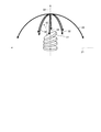
- FIG. 1 is a perspective view schematically showing a hybrid alignment state of a discotic liquid crystal compound.
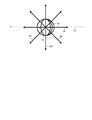
- FIG. 2 is a top view schematically showing a hybrid alignment state of the discotic liquid crystal compound.
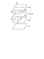
- FIG. 3 is an exploded perspective view showing components of the circularly polarizing plate in the seventh embodiment.
- FIG. 4 is a schematic diagram for explaining the measurement of the surface tension of the liquid crystal composition by the hanging drop method.
- the multilayer film of the present invention includes a long first base material and an optically anisotropic layer.
- the first substrate used in the present invention is a long substrate.
- the “long shape” means a shape having a length of 5 times or more with respect to the width, preferably 10 times or more, and specifically wound in a roll shape.
- the upper limit of the ratio of the length with respect to the width of a film is not specifically limited, For example, it can be 100,000 times or less.
- the first substrate used in the present invention has a surface tension of 35 to 45 mN / m on the surface of the first substrate on the side where the optically anisotropic layer is provided.
- the surface on the side of the first substrate on which the optically anisotropic layer is provided may be simply referred to as the “surface” of the first substrate.
- the surface tension of the surface of the first substrate is preferably 35 mN / m or more, more preferably 37 mN / m or more, and preferably 45 mN / m or less, more preferably 40 mN / m or less.
- the surface tension of the surface of the first substrate can be adjusted to a desired range by appropriately selecting the material constituting the surface, conditions for surface treatment on the surface, and the like. Examples of such surface treatment include corona treatment, plasma treatment, and saponification treatment.
- the surface tension of the first substrate can be measured by using a surface tension meter or contact angle meter to produce droplets using pure water A3 (JIS K0557) as the measurement sample solution. It can be measured by depositing on the sample surface of the material.
- the surface tension of the surface of the first substrate is within the range described above, the surface tension of the surface of the first substrate is outside the range described above.
- it is possible to obtain a high orientation of the optically anisotropic layer which is sufficient for improving the display quality when used in a display device.
- the optically anisotropic layer is used in a liquid crystal display device or an organic electroluminescence display device, it is possible to achieve good display quality with reduced white spots and the like.
- the optically anisotropic layer has high orientation, which means that the crossed Nicols transmittance of the optically anisotropic layer is measured, and the optically anisotropic layer is a display device such as a liquid crystal display device or an organic electroluminescence display device. It can be evaluated by placing it on top and observing the state of the display.
- the 1st base material used in this invention has the orientation control force by extending
- the direction in which the orientation regulating force is exhibited by stretching usually coincides with the orientation direction by stretching.
- the orientation direction by stretching is the orientation direction of the molecules constituting the first base material produced by stretching, and usually coincides with the stretching direction itself.
- the angle formed by the orientation direction of the first base material and the short direction of the first base material may be 0 to 90 °. In particular, the angle may be greater than 0 ° and less than 90 °.
- the multilayer film of the present invention can be a material that enables efficient production of a circularly polarizing plate or the like.
- the angle formed by the orientation direction of the first base material and the short direction of the first base material is preferably 10 ° to 60 °, and particularly preferably 40 ° to 50 °. preferable. By setting it as such an angular relationship, the multilayer film of this invention can be made into the material which enables the efficient manufacture of a specific circularly-polarizing plate.
- the angle formed by the orientation direction of the first substrate and the short direction of the first substrate is preferably 15 ° ⁇ 5 °, 22.5 ⁇ 5 °, 45 ° ⁇ 5 °, 75 ° ⁇ 5 °, more preferably 15 ° ⁇ 4 °, 22.5 ⁇ 4 °, 45 ° ⁇ 4 °, 75 ° ⁇ 4 °, even more preferably 15 ° ⁇ 3 °, 22.5 ° ⁇ 3
- the multilayer film of the present invention can be used as a material that enables efficient production of a specific circularly polarizing plate. .
- Stretching to stretch the base material before stretching to be the first base material may be only oblique stretching, or may be only lateral stretching (stretching in the short direction of the first base material), oblique stretching, You may perform combining longitudinal stretch (stretching to the elongate direction of a 1st base material) and / or lateral stretch.
- the stretching temperature and the stretching ratio at the time of stretching can be appropriately set within a range in which the orientation regulating force is generated on the substrate surface.
- the first substrate may consist of only one layer or may consist of a plurality of layers.
- the 1st base material which consists of a plurality of layers what is provided with the support which consists of one or more layers, and the alignment film provided in the one surface is mentioned.
- the surface on the alignment film side of the first substrate can be a surface on which the optically anisotropic layer is provided.
- the material in the case where the first substrate is composed of only one layer is not particularly limited, and various resins capable of imparting orientation regulating force to the surface by imparting birefringence can be used.
- the resin include resins containing various polymers.
- the polymer include an alicyclic structure-containing polymer, cellulose ester, polyvinyl alcohol, polyimide, polycarbonate, polysulfone, polyethersulfone, epoxy polymer, polystyrene, acrylic polymer, methacrylic polymer, polyethylene, polypropylene, and these. The combination of is mentioned.
- alicyclic structure-containing polymers and cellulose esters are preferable, and alicyclic structure-containing polymers are more preferable.
- These materials can also be used as a support material in the case where the first substrate includes a support and an alignment film.
- An alicyclic structure-containing polymer is an amorphous polymer having an alicyclic structure in a repeating unit, and a polymer containing an alicyclic structure in a main chain and an alicyclic structure in a side chain. Any of the contained polymers can be used.
- Examples of the alicyclic structure include a cycloalkane structure and a cycloalkene structure, and a cycloalkane structure is preferable from the viewpoint of thermal stability.
- the number of carbon atoms constituting one repeating unit of the alicyclic structure is not particularly limited, but is usually 4 to 30, preferably 5 to 20, and more preferably 6 to 15.
- the proportion of the repeating unit having an alicyclic structure in the alicyclic structure-containing polymer is appropriately selected according to the purpose of use, but is usually 50% by weight or more, preferably 70% by weight or more, more preferably 90% by weight. That's it. When there are too few repeating units having an alicyclic structure, the heat resistance of the film may be reduced.
- the alicyclic structure-containing polymer includes (1) a norbornene polymer, (2) a monocyclic olefin polymer, (3) a cyclic conjugated diene polymer, and (4) a vinyl alicyclic hydrocarbon.
- examples thereof include polymers and hydrogenated products thereof.
- norbornene polymers and hydrogenated products thereof are more preferable from the viewpoints of transparency and moldability.
- norbornene polymers include, for example, ring-opening polymers of norbornene monomers, ring-opening copolymers of norbornene monomers with other monomers capable of ring-opening copolymerization, and hydrogenated products thereof; addition polymers of norbornene monomers; Examples include addition copolymers with other monomers copolymerizable with norbornene monomers.
- a ring-opening polymer hydrogenated product of norbornene monomer is most preferable from the viewpoint of transparency.
- the alicyclic structure-containing polymer is selected from known polymers disclosed in, for example, JP-A No. 2002-321302.
- the alicyclic structure-containing polymer has a glass transition temperature of preferably 80 ° C. or higher, more preferably 100 to 250 ° C.
- An alicyclic structure-containing polymer having a glass transition temperature in such a range is excellent in durability without causing deformation or stress in use at high temperatures.
- the molecular weight of the alicyclic structure-containing polymer is converted to polyisoprene measured by gel permeation chromatography (hereinafter abbreviated as “GPC”) using cyclohexane (toluene when the resin is not dissolved) as a solvent.
- the weight average molecular weight (Mw) in terms of polystyrene (when the solvent is toluene) is usually 10,000 to 100,000, preferably 25,000 to 80,000, more preferably 25,000 to 50,000. is there. When the weight average molecular weight is in such a range, the mechanical strength and moldability of the film are highly balanced and suitable.
- the molecular weight distribution (weight average molecular weight (Mw) / number average molecular weight (Mn)) of the alicyclic structure-containing polymer is not particularly limited, but is usually 1 to 10, preferably 1 to 4, more preferably 1.2 to 3. .5 range.
- the resin containing the alicyclic structure-containing polymer has a resin component (that is, an oligomer component) having a molecular weight of 2,000 or less, preferably 5% by weight or less, more preferably 3% by weight or less, and still more preferably 2% by weight or less.
- a resin component that is, an oligomer component
- the amount of the oligomer component can be reduced by appropriately selecting the polymerization catalyst and the hydrogenation catalyst, the reaction conditions such as polymerization and hydrogenation, and the temperature conditions in the step of pelletizing the resin as a molding material.
- the amount of the oligomer component can be measured by the GPC described above.
- the thickness of the first substrate is not particularly limited, but it is easy to improve productivity, reduce the thickness and reduce the weight. Therefore, the thickness is usually 1 to 1000 ⁇ m, preferably 5 to 300 ⁇ m, more preferably 30 to 100 ⁇ m.
- the resin containing the alicyclic structure-containing polymer may be composed only of the alicyclic structure-containing polymer, but may contain any compounding agent as long as the effects of the present invention are not significantly impaired.
- the ratio of the alicyclic structure-containing polymer in the resin containing the alicyclic structure-containing polymer is preferably 70% by weight or more, more preferably 80% by weight or more.
- Preferable specific examples of the resin containing the alicyclic structure-containing polymer include “Zeonor 1420, Zeonor 1420R” manufactured by Nippon Zeon.
- Typical examples of cellulose esters include lower fatty acid esters of cellulose (eg, cellulose acetate, cellulose acetate butyrate, and cellulose acetate propionate).
- Lower fatty acid means a fatty acid having 6 or less carbon atoms per molecule.
- Cellulose acetate includes triacetyl cellulose (TAC) and cellulose diacetate (DAC).
- the degree of acetylation of cellulose acetate is preferably 50 to 70%, particularly preferably 55 to 65%.
- the weight average molecular weight is preferably 70,000 to 120,000, and particularly preferably 80,000 to 100,000.
- the cellulose acetate may be partially esterified with fatty acids such as propionic acid and butyric acid as long as the degree of acetylation is satisfied as well as acetic acid.
- resin which comprises a 1st base material may contain combining cellulose acetate and cellulose esters (cellulose propionate, a cellulose butyrate, etc.) other than a cellulose acetate. In that case, it is preferable that all of these cellulose esters satisfy the above acetylation degree.
- a film of triacetyl cellulose When using a film of triacetyl cellulose, such a film is prepared using a triacetyl cellulose dope prepared by dissolving triacetyl cellulose in a solvent substantially free of dichloromethane by a low temperature dissolution method or a high temperature dissolution method.
- the made triacetyl cellulose film is particularly preferable from the viewpoint of environmental conservation.
- a film of triacetyl cellulose can be produced by a co-casting method. In the co-casting method, raw material flakes of triacetyl cellulose are dissolved in a solvent, and if necessary, an arbitrary additive is added to prepare a solution (dope), and the dope is supported from the dope supply means (die).
- solvents that dissolve raw flakes include halogenated hydrocarbons (dichloromethane, etc.), alcohols (methanol, ethanol, butanol, etc.), esters (methyl formate, methyl acetate, etc.), ethers (dioxane, dioxolane, Diethyl ether and the like).
- solvents that dissolve raw flakes include halogenated hydrocarbons (dichloromethane, etc.), alcohols (methanol, ethanol, butanol, etc.), esters (methyl formate, methyl acetate, etc.), ethers (dioxane, dioxolane, Diethyl ether and the like).
- the additive added to the dope include a retardation increasing agent, a plasticizer, an ultraviolet absorber, a deterioration preventing agent, a slipping agent, and a peeling accelerator.
- Examples of the support for casting the dope include a horizontal endless metal belt and a rotating drum.
- a single dope can be cast as a single layer, or a plurality of layers can be co-cast.
- a low concentration cellulose ester dope layer and a high concentration cellulose ester dope layer provided in contact with the front and back surfaces are formed.
- the dopes can be cast sequentially.
- means for drying the film and removing the solvent include means for transporting the film and passing it through a drying section set to conditions suitable for drying.
- the triacetyl cellulose film include known ones such as TAC-TD80U (manufactured by Fuji Photo Film Co., Ltd.), and those disclosed in JIII Journal of Technical Disclosure No. 2001-1745. It is done.
- the thickness of the triacetyl cellulose film is not particularly limited, but is preferably 20 to 150 ⁇ m, more preferably 40 to 130 ⁇ m, still more preferably 70 to 120 ⁇ m.
- First base material Alignment film
- the material of the alignment film when the first substrate includes a support and an alignment film will be described.
- a material for the alignment film a polymer capable of expressing a desired surface tension and alignment regulating force by stretching can be used.
- polymers as alignment film materials include cellulose, silane coupling agents, polyimide, polyamide, polyvinyl alcohol, epoxy acrylate, silanol oligomer, polyacrylonitrile, phenol resin, polyoxazole, cyclized polyisoprene, and modifications thereof. And mixtures thereof.
- Polyvinyl alcohol is particularly preferable.
- Alignment film is a reverse gravure coating, direct gravure coating, die coating, bar coating, etc. on a support subjected to surface treatment such as corona discharge treatment as needed, a solution in which a polymer is dissolved in water or a solvent, etc. It can form by apply
- a base material before stretching provided with a support and an alignment film is formed by such a process, and further stretched to be used as a first base material.
- the thickness of the alignment film in the first substrate is not particularly limited, and can be adjusted to a thickness at which a desired alignment regulating force can be obtained.
- the thickness of the alignment film is preferably 0.05 ⁇ m or more, more preferably 0.1 ⁇ m or more, while preferably 10 ⁇ m or less, more preferably 5 ⁇ m or less.
- the method for producing the first substrate is not particularly limited, and can be produced by molding and stretching the material described above by a known method.
- stretching is performed by a multi-layer extrusion method, a method in which a part of the layer is formed and then another layer is applied to the surface by an operation such as coating or vapor deposition.
- a method of forming a previous base material and stretching it may be employed.
- surface treatment is performed in order to adjust the surface tension of the surface of the first base material, it is preferable to perform the surface treatment before the stretching and then perform the stretching in order to develop the orientation regulating force well.
- optically anisotropic layer in the multilayer film of the present invention comprises an optically anisotropic layer containing cured liquid crystal molecules provided directly on the surface of the first substrate.
- the “cured liquid crystal molecule” means a molecule of the compound when a compound capable of exhibiting a liquid crystal phase is turned into a solid while exhibiting a liquid crystal phase.
- the cured liquid crystal molecules include those obtained by curing a curable liquid crystal compound, and more specifically, a polymer obtained by polymerizing a polymerizable liquid crystal compound.
- this specific optically anisotropic layer containing cured liquid crystal molecules is simply referred to as an “optically anisotropic layer”.
- optically anisotropic layer“ directly ”on the surface of the first substrate is to form the optically anisotropic layer on the surface of the first substrate without any other layers.
- An optically anisotropic layer sufficient to provide good display quality when used in a display device by directly providing an optically anisotropic layer on the surface of the first substrate having a specific surface tension High orientation can be obtained.
- the formation of the optically anisotropic layer on the first substrate typically involves Step (I): A step of applying a liquid crystal composition containing a curable liquid crystal compound on a long first substrate to form a layer of the liquid crystal composition, Step (II): A step of causing the curable liquid crystal compound in the layer of the liquid crystal composition to be homogeneously or hybridally aligned along substantially the same direction as the alignment direction of the first substrate, and Step (III): curable It can be performed by a method including a step of polymerizing a liquid crystal compound to form cured liquid crystal molecules.
- Step (I) can be performed by directly applying the liquid crystal composition onto one surface of the first substrate that is continuously conveyed.
- coating methods include curtain coating, extrusion coating, roll coating, spin coating, dip coating, bar coating, spray coating, slide coating, print coating, gravure coating, and die coating.
- Method, cap coating method, and dipping method For example, in the die coating method, when the lip direction of the die coater is arranged so as to be parallel to the short direction of the base material, the application direction of the liquid crystal composition is the same as the transport direction of the base material, that is, the long direction of the base material.
- the thickness of the liquid crystal composition layer to be applied can be appropriately set according to the desired thickness required for the optically anisotropic layer.
- the liquid crystal composition is preferably a liquid having a specific surface tension.
- the surface tension of the liquid crystal composition is preferably 20 mN / m or more, more preferably 25 mN / m or more, and preferably 35 mN / m or less, more preferably 30 mN / m or less.
- the surface tension of the first substrate is within the specific range described above, the surface tension of the liquid crystal composition is within this range, whereby the liquid crystal composition is applied to the surface of the first substrate. It is possible to easily apply in a state where there are few planar defects such as repellency, and as a result, an optically anisotropic layer having good optical characteristics can be easily produced.
- the method of setting the surface tension value of the liquid crystal composition within the above range is not particularly limited, but for example, by appropriately selecting the type and content ratio of the solvent, surfactant and other additives in the liquid crystal composition, the liquid crystal composition
- the surface tension of the object can be adjusted.
- the measurement of the surface tension of the liquid crystal composition can be calculated by, for example, using a surface tension meter to prepare a quantitative droplet and analyzing it by the formula II using the hanging droplet method.
- Formula II ⁇ L surface tension of liquid crystal composition
- ⁇ liquid density de: maximum droplet diameter
- H ⁇ 1 correction term obtained from ds / de ds: diameter at the position where the liquid bottom de is raised
- the step (II) may be achieved immediately by coating. In that case, a separate operation is not required. However, the step (II) may be achieved by applying an orientation treatment such as heating after the coating, if necessary. There is also.
- the alignment treatment conditions can be appropriately set according to the properties of the liquid crystal composition to be used. For example, the alignment treatment may be performed at a temperature of 50 to 160 ° C. for 30 seconds to 5 minutes. By appropriately setting the composition and processing conditions of the liquid crystal composition to be used, alignment along substantially the same direction as the alignment direction by stretching of the first substrate can be achieved.
- a step of drying the liquid crystal composition layer may be performed as necessary.
- drying can be achieved by a drying method such as natural drying, heat drying, reduced pressure drying, and reduced pressure heat drying.
- a drying method such as natural drying, heat drying, reduced pressure drying, and reduced pressure heat drying.
- a method suitable for the properties of the components (polymerizable compound, polymerization initiator, etc.) of the liquid crystal composition can be appropriately selected.
- examples thereof include a method of irradiating active energy rays and a thermal polymerization method.
- a method of irradiating active energy rays is preferable because the reaction can proceed at room temperature without requiring heating.
- the irradiated active energy rays can include light such as visible light, ultraviolet light, and infrared light, and arbitrary energy rays such as electron beams.
- a method of irradiating light such as ultraviolet rays is preferable because the operation is simple.
- the temperature during ultraviolet irradiation is preferably 30 ° C. or lower.
- the lower limit of the temperature during ultraviolet irradiation can be 15 ° C. or higher.
- Ultraviolet irradiation intensity is usually, 0.1mW / cm 2 ⁇ 1000mW / cm 2 range, preferably in the range of 0.5mW / cm 2 ⁇ 600mW / cm 2.
- the ultraviolet irradiation time is in the range of 1 second to 300 seconds, preferably in the range of 5 seconds to 100 seconds.
- UV integrated light quantity (mJ / cm 2 ) ultraviolet irradiation intensity (mW / cm 2 ) ⁇ irradiation time (seconds)
- a high pressure mercury lamp, a metal halide lamp, or a low pressure mercury lamp can be used.
- the optically anisotropic layer has a slow axis along substantially the same direction as the orientation direction due to stretching of the first substrate.
- the cured liquid crystal molecules contained in the optically anisotropic layer exhibit alignment regularity due to the alignment regulating force of the first substrate, thereby controlling the direction of the slow axis.
- the cured liquid crystal molecules can have homogeneous alignment regularity or hybrid alignment regularity.
- the cured liquid crystal molecules are a cured product of a discotic liquid crystal compound, and in this embodiment, the liquid crystal molecules can be hybrid-aligned.
- FIGS. 1 and 2 are a perspective view and a top view schematically showing a hybrid alignment state of a discotic liquid crystal compound.
- 1 and 2 show a state where the discotic liquid crystal compound 11 is aligned on the surface of the first substrate placed in a horizontal direction (a direction orthogonal to the arrow 22).
- the orientation direction due to the stretching of the first substrate is indicated by an arrow 21.
- the lower molecules that is, the molecules near the surface of the first base material are horizontally aligned, while the upper molecules are inclined in the direction of the arrow 15.
- Such a hybrid alignment of the discotic liquid crystal compounds causes the refractive index anisotropy of the optically anisotropic layer to change from the polar angle 0 ° direction (the direction of the arrow 22) and the polar angle 0 ° direction to the arrows 31 to 34. As shown, it can be confirmed by measuring from directions inclined at various azimuth angles and polar angles.
- the layer of the disk-like liquid crystal compound thus hybrid-aligned usually has a slow axis in the direction in which the arrow 15 is inclined, and therefore has a slow axis in the direction of the normal arrow 21.
- “having homogeneous alignment regularity” means that the average direction of the line obtained by projecting the long axis direction of the mesogen of the cured liquid crystal molecule onto the surface of the first substrate is one direction that is horizontal to the surface ( For example, it is aligned in the direction of the surface director of the base film.
- the homogeneous alignment regularity “along” in a predetermined direction means that the alignment direction is substantially in the same direction as the predetermined direction.
- the predetermined direction may be an orientation direction by stretching the first substrate.
- Whether or not the cured liquid crystal molecules have homogeneous alignment regularity and the alignment direction are determined by measuring the slow axis direction using a phase difference meter represented by AxoScan (manufactured by Axometrics), and the slow phase This can be confirmed by measuring the retardation distribution at each incident angle in the axial direction and in the direction orthogonal to the slow axis.
- AxoScan manufactured by Axometrics
- the major axis direction of the mesogen of the polymerizable liquid crystal compound is usually the mesogen of the cured liquid crystal molecule. It becomes the major axis direction.
- a plurality of types of mesogens having different orientation directions are present in the optically anisotropic layer as in the case of using a reverse wavelength dispersion polymerizable liquid crystal compound (described later) as the polymerizable liquid crystal compound,
- the direction in which the long axis directions of the longest types of mesogens are aligned is the alignment direction.
- the orientation direction by the stretching of the first substrate and the slow axis along the “substantially” same direction the angle formed by the orientation direction by the stretching of the first substrate and the slow axis, It means within 5 degrees.
- the angle is preferably within 3 °, more preferably within 1 °.
- the orientation direction by stretching of the first base material is substantially the same as the optically anisotropic layer.
- An alignment regularity along the same direction can be imparted, and as a result, an optically anisotropic layer having such an alignment regularity can be obtained.
- the thickness of the optically anisotropic layer is not particularly limited, and can be appropriately adjusted so that properties such as retardation can be within a desired range.
- the lower limit of the thickness is preferably 0.5 ⁇ m or more, more preferably 1.0 ⁇ m or more, while the upper limit of the thickness is preferably 10 ⁇ m or less, and is 7 ⁇ m or less. Is more preferable, and it is still more preferable that it is 5 micrometers or less.
- the shape, length and width of the optically anisotropic layer can be a long film-like shape similar to that of the first substrate, and this can be made into a rectangle suitable for the desired application as required. It can be cut into shapes.
- the optically anisotropic layer preferably has reverse wavelength dispersion. That is, the optically anisotropic layer preferably has chromatic dispersion that exhibits a high in-plane retardation with respect to transmitted light having a longer wavelength than a short wavelength.
- the optically anisotropic layer preferably has such reverse wavelength dispersion in at least a part of the visible light band, preferably all. Since the optically anisotropic layer has reverse wavelength dispersion, the function can be expressed uniformly in a wide band in optical applications such as a ⁇ / 4 wavelength plate or a ⁇ / 2 wavelength plate.
- the optically anisotropic layer has optical characteristics that can be used as a ⁇ / 4 wavelength plate or a ⁇ / 2 wavelength plate. Specifically, when the in-plane retardation Re measured at a measurement wavelength of 550 nm is in the range of 108 nm to 168 nm, it can be used as a ⁇ / 4 wavelength plate. When the in-plane retardation Re measured at a measurement wavelength of 550 nm is in the range of 245 nm to 305 nm, it can be used as a ⁇ / 2 wavelength plate.
- the in-plane retardation Re measured at a measurement wavelength of 550 nm is preferably in the range of 128 nm to 148 nm, more preferably 133 nm to 143 nm.
- the in-plane retardation Re measured at a measurement wavelength of 550 nm is preferably in the range of 265 nm to 285 nm, more preferably 270 nm to 280 nm.
- the in-plane retardation Re is calculated according to the following formula.
- nx is the refractive index in the slow axis direction in the plane of the optically anisotropic layer (maximum refractive index in the plane), and ny is the optical anisotropy.
- the refractive index in the direction perpendicular to the slow axis in the plane of the layer, and d is the thickness (nm) of the optically anisotropic layer.
- the angle formed by the slow axis of the optically anisotropic layer and the short direction of the optically anisotropic layer is the same as the angle formed by the orientation direction of the first base material and the short direction of the first base material. sell.
- the angle formed by the slow axis of the optically anisotropic layer and the short direction of the optically anisotropic layer can be specifically 0 ° to 90 °.
- the angle formed by the slow axis of the optically anisotropic layer and the short direction of the optically anisotropic layer is particularly preferably 40 ° to 50 °.
- the angle formed by the slow axis of the optically anisotropic layer and the short direction of the optically anisotropic layer is preferably 15 ° ⁇ 5 °, 22.5 ⁇ 5 °, 45 ° ⁇ 5.
- Specific ranges such as 3 °, 45 ° ⁇ 3 °, and 75 ° ⁇ 3 ° can be used.
- the multilayer film of the present invention can be a material that enables efficient production of a specific circularly polarizing plate.
- composition (A) A liquid crystal composition containing a polymerizable liquid crystal compound (hereinafter, the composition may be abbreviated as “composition (A)”) that can be used in the production of the multilayer film of the present invention will be described.
- the liquid crystal compound as a component of the composition (A) is a compound that can exhibit a liquid crystal phase when blended and oriented in the composition (A).
- the polymerizable liquid crystal compound is a liquid crystal compound that can be polymerized in the composition (A) in a state of exhibiting such a liquid crystal phase and can be a polymer while maintaining the molecular orientation in the liquid crystal phase.
- the reverse wavelength dispersion polymerizable liquid crystal compound is a polymerizable liquid crystal compound in which, when such a polymer is used, the obtained polymer exhibits reverse wavelength dispersion.
- compounds having a polymerizable property such as a polymerizable liquid crystal compound and other polymerizable compounds which are components of the composition (A) may be simply referred to as “polymerizable compound”. .
- polymerizable liquid crystal compound examples include various disc-shaped liquid crystal compounds and rod-shaped liquid crystal compounds.
- the discotic liquid crystal compound examples include various compounds having a discotic core (discotic core) and a polymerizable group and exhibiting a liquid crystal phase.
- the discotic liquid crystal compound has an optically negative uniaxial property.
- those capable of hybrid alignment are particularly preferable.
- An optically anisotropic layer formed using a discotic liquid crystal compound and hybrid-aligned is useful, for example, for improving the viewing angle characteristics of a TN liquid crystal cell.
- a discotic liquid crystal compound a compound having a crosslinking group such as an epoxy group or an acrylate group at the end of the side chain is used, and the alignment structure can be kept thermally stable by crosslinking in the discotic nematic phase formation temperature range. it can.
- discotic liquid crystal compounds include the following discotic liquid crystal compounds D1 to D3.
- —O—C ( ⁇ O) —C n H 2n —O—C ( ⁇ O) —CH ⁇ CH 2 , —O—C ( ⁇ O) —Ph—O—C n H 2n —O —C ( ⁇ O) —CH ⁇ CH 2 and —O—C ( ⁇ O) —Ph—O—C n H 2n —O—CH ⁇ CH 2 are preferred, —O—C ( ⁇ O) —Ph —O—C n H 2n —O—C ( ⁇ O) —CH ⁇ CH 2 is more preferred.
- n is preferably a natural number of 3 to 10, more preferably a natural number of 4 to 8.
- X is CH 2 , O, S, or NH. Among these, CH 2 or O is preferable, and CH 2 is more preferable.
- discotic liquid crystalline compound examples include JP-A-8-50206 and literature (C. Destrade et al., Mol. Crysr. Liq. Cryst., Vol. 71, page 111 (1981); The Chemical Society of Japan, Quarterly Chemistry Review, No. 22, Liquid Crystal Chemistry, Chapter 5, Chapter 10, Section 2 (1994); B. Kohne et al., Angew. Chem. Soc. Chem. Comm., Page 1794 (1985); J. Zhang et al., J. Am. Chem. Soc., Vol. 116, page 2655 (1994)).
- the resulting optically anisotropic layer is negatively charged.
- the values of n2 and n3 do not have to be exactly equal, and if they are approximately equal, it may be assumed to have negative uniaxiality.
- ) ⁇ 0.2 Can be put to practical use as a layer having negative uniaxiality.
- the optical axis has an inclination ⁇ of 5 from the normal direction of the surface of the optically anisotropic layer.
- the angle is preferably from 60 ° to 60 °, more preferably from 10 ° to 50 °, and most preferably from 20 ° to 40 °.
- the further optically anisotropic layer preferably satisfies the condition of 50 ⁇ Re ⁇ 400 (nm).
- rod-like liquid crystal compound examples include JP 2002-030042, JP 2004-204190, JP 2005-263789, JP 2007-119415, JP 2007-186430, and Examples thereof include rod-like liquid crystal compounds having a polymerizable group described in Kaihei 11-513360. Further, examples of preferable liquid crystal compounds include “LC242” manufactured by BASF and the like. A liquid crystal compound may be used individually by 1 type, and may be used combining two or more types by arbitrary ratios.
- the refractive index anisotropy ⁇ n of the rod-like liquid crystal compound is preferably 0.02 or more, more preferably 0.05 or more, preferably 0.30 or less, more preferably 0.25 or less. If the refractive index anisotropy ⁇ n is less than 0.02, the thickness of the liquid crystal resin layer may be increased in order to obtain a desired optical function, and the alignment uniformity may be lowered. is there. If the refractive index anisotropy ⁇ n is greater than 0.30, the thickness of the liquid crystal resin layer becomes thin in order to obtain a desired optical function, which is disadvantageous for the thickness accuracy.
- the absorption edge on the long wavelength side of the ultraviolet absorption spectrum of the liquid crystal resin layer may reach the visible range. It can be used as long as the performance is not adversely affected.
- the refractive index anisotropy of the liquid crystal compound is directly used as the refractive index anisotropy of the liquid crystal compound in the composition for forming a liquid crystal layer.
- the refractive index anisotropy ⁇ n determined from the value of the refractive index anisotropy ⁇ n of each liquid crystal compound and the content ratio of each liquid crystal compound.
- the value of the refractive index anisotropy ⁇ n can be measured by the Senarmon method.
- One of these liquid crystal compounds and the reverse wavelength dispersion polymerizable liquid crystal compound described below may be used alone, or two or more thereof may be used in combination at any ratio.
- a reverse wavelength dispersion polymerizable liquid crystal compound may be used as a part or all of the polymerizable liquid crystal compound.
- an optically anisotropic layer having reverse wavelength dispersion can be easily obtained.
- Examples of the reverse wavelength dispersion polymerizable liquid crystal compound include a compound having a main chain mesogen and a side chain mesogen bonded to the main chain mesogen in the molecule.
- the side chain mesogen can be aligned in a different direction from the main chain mesogen. Therefore, in the optically anisotropic layer, the main chain mesogen and the side chain mesogen can be oriented in different directions. Such an orientation allows the optically anisotropic layer to exhibit reverse wavelength dispersion characteristics.
- Examples of the reverse wavelength dispersion polymerizable liquid crystal compound include a compound represented by the following formula (I) (hereinafter sometimes referred to as “compound (I)”).
- Y 1 to Y 8 are each independently a chemical single bond, —O—, —S—, —O—C ( ⁇ O) —, —C ( ⁇ O) —O—, —O. —C ( ⁇ O) —O—, —NR 1 —C ( ⁇ O) —, —C ( ⁇ O) —NR 1 —, —O—C ( ⁇ O) —NR 1 —, —NR 1 —C ( ⁇ O) —O—, —NR 1 —C ( ⁇ O) —NR 1 —, or —NR 1 —O— is represented.
- R 1 represents a hydrogen atom or an alkyl group having 1 to 6 carbon atoms.
- alkyl group having 1 to 6 carbon atoms of R 1 include methyl group, ethyl group, n-propyl group, isopropyl group, n-butyl group, sec-butyl group, t-butyl group, n-pentyl group, n- A hexyl group etc. are mentioned.
- R 1 is preferably a hydrogen atom or an alkyl group having 1 to 4 carbon atoms.
- Y 1 to Y 8 are each independently a chemical single bond, —O—, —O—C ( ⁇ O) —, —C ( ⁇ O) —O—, or , —O—C ( ⁇ O) —O— is preferable.
- G 1 and G 2 each independently represent a divalent aliphatic group having 1 to 20 carbon atoms, which may have a substituent.
- the divalent aliphatic group having 1 to 20 carbon atoms include a divalent aliphatic group having a chain structure such as an alkylene group having 1 to 20 carbon atoms and an alkenylene group having 2 to 20 carbon atoms; And divalent aliphatic groups such as a cycloalkanediyl group having 20 carbon atoms, a cycloalkenediyl group having 4 to 20 carbon atoms, and a divalent alicyclic fused ring group having 10 to 30 carbon atoms.
- Examples of the substituent for the divalent aliphatic group of G 1 and G 2 include halogen atoms such as fluorine atom, chlorine atom, bromine atom and iodine atom; methoxy group, ethoxy group, n-propoxy group, isopropoxy group, n -Butoxy group, sec-butoxy group, t-butoxy group, n-pentyloxy group, n-hexyloxy group and the like, such as alkoxy groups having 1 to 6 carbon atoms; Of these, a fluorine atom, a methoxy group, and an ethoxy group are preferable.
- the aliphatic group includes —O—, —S—, —O—C ( ⁇ O) —, —C ( ⁇ O) —O—, —O—C ( ⁇ O) —O—, — NR 2 —C ( ⁇ O) —, —C ( ⁇ O) —NR 2 —, —NR 2 —, or —C ( ⁇ O) — may be present.
- R 2 represents the same hydrogen atom or alkyl group having 1 to 6 carbon atoms as R 1, and is preferably a hydrogen atom or a methyl group.
- the group intervening in the aliphatic group is preferably —O—, —O—C ( ⁇ O) —, —C ( ⁇ O) —O—, —C ( ⁇ O) —.
- G 1 and G 2 are each independently an alkylene group having 1 to 20 carbon atoms, an alkenylene group having 2 to 20 carbon atoms, or the like, from the viewpoint of better expressing the desired effect of the present invention.
- a divalent aliphatic group having a chain structure is preferable.
- Z 1 and Z 2 each independently represents an alkenyl group having 2 to 10 carbon atoms which is unsubstituted or substituted with a halogen atom.
- the alkenyl group preferably has 2 to 6 carbon atoms.
- Examples of the halogen atom that is a substituent of the alkenyl group of Z 1 and Z 2 include a fluorine atom, a chlorine atom, a bromine atom, and the like, and a chlorine atom is preferable.
- alkenyl group having 2 to 10 carbon atoms of Z 1 and Z 2 include CH 2 ⁇ CH—, CH 2 ⁇ C (CH 3 ) —, CH 2 ⁇ CH—CH 2 —, CH 3 —CH ⁇ .
- Z 1 and Z 2 are each independently CH 2 ⁇ CH—, CH 2 ⁇ C (CH 3 ) —, CH 2 ⁇
- C (Cl) —, CH 2 ⁇ CH—CH 2 —, CH 2 ⁇ C (CH 3 ) —CH 2 —, or CH 2 ⁇ C (CH 3 ) —CH 2 —CH 2 — is preferred.
- CH 2 ⁇ CH—, CH 2 ⁇ C (CH 3 ) —, or CH 2 ⁇ C (Cl) — is more preferable, and CH 2 ⁇ CH— is particularly preferable.
- a x represents an organic group having 2 to 30 carbon atoms having at least one aromatic ring selected from the group consisting of an aromatic hydrocarbon ring and an aromatic heterocyclic ring.
- the “aromatic ring” is represented by a cyclic structure having a broad sense of aromaticity according to the Huckle rule, that is, a cyclic conjugated structure having (4n + 2) ⁇ electrons, and thiophene, furan, benzothiazole, and the like. This means that a lone pair of heteroatoms such as sulfur, oxygen, and nitrogen is involved in the ⁇ -electron system and exhibits aromaticity.
- the organic group having 2 to 30 carbon atoms and having at least one aromatic ring selected from the group consisting of an aromatic hydrocarbon ring and an aromatic heterocyclic ring of A x may have a plurality of aromatic rings. And having an aromatic hydrocarbon ring and an aromatic heterocycle.
- aromatic hydrocarbon ring examples include a benzene ring, a naphthalene ring, and an anthracene ring.
- aromatic heterocyclic ring examples include monocyclic aromatic heterocyclic rings such as a pyrrole ring, a furan ring, a thiophene ring, a pyridine ring, a pyridazine ring, a pyrimidine ring, a pyrazine ring, a pyrazole ring, an imidazole ring, an oxazole ring, and a thiazole ring; Benzothiazole ring, benzoxazole ring, quinoline ring, phthalazine ring, benzimidazole ring, benzopyrazole ring, benzofuran ring, benzothiophene ring, thiazolopyridine ring, oxazolopyridine ring, thiazolopyrazine ring,
- the aromatic ring of A x may have a substituent.
- substituents include halogen atoms such as fluorine atom and chlorine atom; cyano group; alkyl group having 1 to 6 carbon atoms such as methyl group, ethyl group and propyl group; and 2 to 6 carbon atoms such as vinyl group and allyl group.
- An alkyl group having 1 to 6 carbon atoms such as a trifluoromethyl group; a substituted amino group such as a dimethylamino group; an alkoxy group having 1 to 6 carbon atoms such as a methoxy group, an ethoxy group, and an isopropoxy group; Nitro group; aryl group such as phenyl group and naphthyl group; —C ( ⁇ O) —R 5 ; —C ( ⁇ O) —OR 5 ; —SO 2 R 6 ;
- R 5 represents an alkyl group having 1 to 20 carbon atoms, an alkenyl group having 2 to 20 carbon atoms, or a cycloalkyl group having 3 to 12 carbon atoms
- R 6 is a carbon atom similar to R 4 described later. It represents an alkyl group having 1 to 20 carbon atoms, an alkenyl group having 2 to 20 carbon atoms, a phenyl group, or a 4-methylphenyl group.
- the aromatic ring within A x may have a plurality of identical or different substituents, bonded two adjacent substituents together may form a ring.
- the ring formed may be a single ring or a condensed polycycle, and may be an unsaturated ring or a saturated ring.
- the “carbon number” of the organic group having 2 to 30 carbon atoms in A x means the total number of carbon atoms in the whole organic group not including the carbon atom of the substituent (the same applies to A y described later). .
- an aromatic hydrocarbon ring group As the organic group having 2 to 30 carbon atoms and having at least one aromatic ring selected from the group consisting of an aromatic hydrocarbon ring and an aromatic heterocyclic ring of A x , an aromatic hydrocarbon ring group; an aromatic heterocyclic ring Group: an alkyl group having 3 to 30 carbon atoms having at least one aromatic ring selected from the group consisting of an aromatic hydrocarbon ring group and an aromatic heterocyclic group; from an aromatic hydrocarbon ring group and an aromatic heterocyclic group An alkenyl group having 4 to 30 carbon atoms having at least one aromatic ring selected from the group consisting of: a carbon number having at least one aromatic ring selected from the group consisting of an aromatic hydrocarbon ring group and an aromatic heterocyclic group 4-30 alkynyl groups; and the like.
- a x is not limited to the following.
- “-” represents a bond extending from any position of the ring (the same applies hereinafter).
- E represents NR 6a , an oxygen atom or a sulfur atom.
- R 6a represents a hydrogen atom; or an alkyl group having 1 to 6 carbon atoms such as a methyl group, an ethyl group, or a propyl group.
- X, Y, and Z each independently represent NR 7 , an oxygen atom, a sulfur atom, —SO—, or —SO 2 — (provided that an oxygen atom, a sulfur atom, —SO—, Except where —SO 2 — are adjacent to each other).
- R 7 represents the same hydrogen atom as R 6a ; or an alkyl group having 1 to 6 carbon atoms such as a methyl group, an ethyl group, or a propyl group.
- an aromatic hydrocarbon group having 6 to 30 carbon atoms or is preferably an aromatic heterocyclic group having 4 to 30 carbon atoms, more preferably one of the groups shown below ,
- the ring of A x may have a substituent.
- substituents include halogen atoms such as fluorine atom and chlorine atom; cyano group; alkyl group having 1 to 6 carbon atoms such as methyl group, ethyl group and propyl group; and 2 to 6 carbon atoms such as vinyl group and allyl group.
- An alkyl group having 1 to 6 carbon atoms such as a trifluoromethyl group; a substituted amino group such as a dimethylamino group; an alkoxy group having 1 to 6 carbon atoms such as a methoxy group, an ethoxy group, and an isopropoxy group; Nitro group; aryl group such as phenyl group and naphthyl group; —C ( ⁇ O) —R 8 ; —C ( ⁇ O) —OR 8 ; —SO 2 R 6 ; R 8 represents an alkyl group having 1 to 6 carbon atoms such as a methyl group or an ethyl group; or an aryl group having 6 to 14 carbon atoms such as a phenyl group.
- a halogen atom, a cyano group, an alkyl group having 1 to 6 carbon atoms, and an alkoxy group having 1 to 6 carbon atoms are preferable.
- the ring of A x may have a plurality of the same or different substituents, and two adjacent substituents may be bonded together to form a ring.
- the ring formed may be monocyclic or condensed polycyclic.
- the “carbon number” of the organic group having 2 to 30 carbon atoms in A x means the total number of carbon atoms in the whole organic group not including the carbon atom of the substituent (the same applies to A y described later). .
- a y has a hydrogen atom, an optionally substituted alkyl group having 1 to 20 carbon atoms, an optionally substituted alkenyl group having 2 to 20 carbon atoms, and a substituent.
- a cycloalkyl group having 3 to 12 carbon atoms, an alkynyl group having 2 to 20 carbon atoms which may have a substituent, —C ( ⁇ O) —R 3 , —SO 2 —R 4 , —C ( S) NH-R 9 or an organic group having 2 to 30 carbon atoms having at least one aromatic ring selected from the group consisting of an aromatic hydrocarbon ring and an aromatic heterocyclic ring.
- R 3 has an optionally substituted alkyl group having 1 to 20 carbon atoms, an optionally substituted alkenyl group having 2 to 20 carbon atoms, and a substituent.
- R 9 is an optionally substituted alkyl group having 1 to 20 carbon atoms, an optionally substituted alkenyl group having 2 to 20 carbon atoms, A cycloalkyl group having 3 to 12 carbon atoms which may have a substituent and an aromatic group having 5 to 20 carbon atoms which may have a substituent are represented.
- alkyl group having 1 to 20 carbon atoms that may have a substituent of A y include a methyl group, an ethyl group, an n-propyl group, an isopropyl group, and n-butyl.
- alkenyl group having 2 to 20 carbon atoms which may have a substituent of A y include a vinyl group, a propenyl group, an isopropenyl group, a butenyl group, an isobutenyl group, and a pentenyl group.
- the carbon number of the alkenyl group having 2 to 20 carbon atoms which may have a substituent is preferably 2 to 12.
- Examples of the cycloalkyl group having 3 to 12 carbon atoms of the cycloalkyl group having 3 to 12 carbon atoms which may have a substituent include a cyclopropyl group, a cyclobutyl group, a cyclopentyl group, a cyclohexyl group, and a cyclooctyl group. Groups and the like.
- alkynyl group having 2 to 20 carbon atoms of the alkynyl group having 2 to 20 carbon atoms which may have a substituent examples include an ethynyl group, a propynyl group, a 2-propynyl group (propargyl group), and a butynyl group.
- Examples of the substituent of the alkyl group having 1 to 20 carbon atoms which may have a substituent and the alkenyl group having 2 to 20 carbon atoms which may have a substituent include a fluorine atom, chlorine Halogen atoms such as atoms; cyano groups; substituted amino groups such as dimethylamino groups; alkoxy groups having 1 to 20 carbon atoms such as methoxy groups, ethoxy groups, isopropoxy groups, butoxy groups; methoxymethoxy groups, methoxyethoxy groups, etc.
- R 7a and R 10 are each independently an alkyl group having 1 to 20 carbon atoms, an alkenyl group having 2 to 20 carbon atoms, a cycloalkyl group having 3 to 12 carbon atoms, or a 6 to 12 carbon atom.
- R 8a represents an alkyl group having 1 to 20 carbon atoms, an alkenyl group having 2 to 20 carbon atoms, a phenyl group, or a 4-methylphenyl group similar to R 4 described above.
- Examples of the substituent of the cycloalkyl group having 3 to 12 carbon atoms which may have a substituent for A y include a halogen atom such as a fluorine atom and a chlorine atom; a cyano group; a substituted amino group such as a dimethylamino group; C1-C6 alkyl groups such as methyl, ethyl and propyl groups; C1-C6 alkoxy groups such as methoxy, ethoxy and isopropoxy groups; nitro groups; aryls such as phenyl and naphthyl groups A cycloalkyl group having 3 to 8 carbon atoms such as a cyclopropyl group, a cyclopentyl group, and a cyclohexyl group; —C ( ⁇ O) —R 7a ; —C ( ⁇ O) —OR 7a ; —SO 2 R 8a ; And the like.
- R 7a and R 8a represent
- Examples of the substituent of the alkynyl group having 2 to 20 carbon atoms that may have a substituent of A y include an alkyl group having 1 to 20 carbon atoms that may have a substituent and a substituent. And the same substituent as the substituent of the alkenyl group having 2 to 20 carbon atoms which may be used.
- R 3 may have a C 1-20 alkyl group which may have a substituent, or may have a substituent.
- Preferred examples thereof include an alkenyl group having 2 to 20 carbon atoms, an optionally substituted cycloalkyl group having 3 to 12 carbon atoms, and an aromatic hydrocarbon group having 5 to 12 carbon atoms.
- Specific examples thereof include the alkyl group having 1 to 20 carbon atoms which may have a substituent, the alkenyl group having 2 to 20 carbon atoms which may have a substituent, and a substituent of the above Ay.
- Examples of the cycloalkyl group having 3 to 12 carbon atoms which may be included are the same as those listed.
- R 4 is an alkyl group having 1 to 20 carbon atoms, an alkenyl group having 2 to 20 carbon atoms, a phenyl group, or a 4-methylphenyl group To express.
- Specific examples of the alkyl group having 1 to 20 carbon atoms and the alkenyl group having 2 to 20 carbon atoms in R 4 include the alkyl group having 1 to 20 carbon atoms and the alkenyl group having 2 to 20 carbon atoms in the above Ay . Examples are the same as those listed.
- Examples of the organic group having 2 to 30 carbon atoms and having at least one aromatic ring selected from the group consisting of an aromatic hydrocarbon ring and an aromatic heterocyclic ring for A y are the same as those exemplified for A x above. Is mentioned.
- a hydrogen atom an optionally substituted alkyl group having 1 to 20 carbon atoms, an optionally substituted alkenyl group having 2 to 20 carbon atoms, and a substituent
- R 3 and R 4 represent the same meaning as described above.
- an alkyl group having 1 to 20 carbon atoms which may have a substituent an alkenyl group having 2 to 20 carbon atoms which may have a substituent, and an optionally substituted carbon
- substituent of the alkynyl group having 2 to 20 carbon atoms include a halogen atom, a cyano group, an alkoxy group having 1 to 20 carbon atoms, an alkoxy group having 1 to 12 carbon atoms substituted with an alkoxy group having 1 to 12 carbon atoms, phenyl Group, cyclohexyl group, C2-C12 cyclic ether group, C6-C14 aryloxy group, hydroxyl group, benzodioxanyl group, phenylsulfonyl group, 4-methylphenylsulfonyl group, benzoyl group, -SR 10 Is preferred.
- R 10 represents the same meaning as described above.
- a y having an optionally substituted cycloalkyl group having 3 to 12 carbon atoms, an optionally substituted aromatic hydrocarbon group having 6 to 12 carbon atoms, and a substituent.
- the substituent of the aromatic heterocyclic group having 3 to 9 carbon atoms a fluorine atom, an alkyl group having 1 to 6 carbon atoms, an alkoxy group having 1 to 6 carbon atoms, and a cyano group are preferable.
- a x and A y may be combined to form a ring.
- a ring examples include an unsaturated heterocyclic ring having 4 to 30 carbon atoms and an unsaturated carbocyclic ring having 6 to 30 carbon atoms, which may have a substituent.
- the unsaturated heterocyclic ring having 4 to 30 carbon atoms and the unsaturated carbocyclic ring having 6 to 30 carbon atoms are not particularly limited and may or may not have aromaticity.
- the ring shown below is mentioned.
- the ring shown below is the one in the formula (I).
- substituent groups include the same ones as exemplified as the substituents of the aromatic ring within A x.
- the total number of ⁇ electrons contained in A x and A y is preferably 4 or more and 24 or less, more preferably 6 or more and 20 or less, from the viewpoint of better expressing the desired effect of the present invention. More preferably, it is 6 or more and 18 or less.
- a x is an aromatic hydrocarbon group or aromatic heterocyclic group having 4 to 30 carbon atoms
- a y is a hydrogen atom, a cycloalkyl group having 3 to 8 carbon atoms, (halogen atom, cyano group,
- An aromatic hydrocarbon group having 6 to 12 carbon atoms which may have a substituent of an alkyl group having 1 to 6 carbon atoms, an alkoxy group having 1 to 6 carbon atoms, or a cycloalkyl group having 3 to 8 carbon atoms) , (Halogen atom, alkyl group having 1 to 6 carbon atoms, alkoxy group having 1 to 6 carbon atoms, cyano group) which may have as a substituent a C 3-9 aromatic heterocyclic group or substituent An optionally substituted alkyl group having 1 to 20 carbon atoms, an optionally substituted alkenyl group having 1 to 20 carbon atoms, and an optionally substituted alkyl group having 1 to 20 carbon atoms, and an optional
- the substituent is a halogen atom, a cyano group, or an aryl group having 1 to 20 carbon atoms.
- R 10 represents the same meaning as described above.
- a x is any of the groups having the following structure
- a y is a hydrogen atom, a cycloalkyl group having 3 to 8 carbon atoms, (a halogen atom, a cyano group, an alkyl group having 1 to 6 carbon atoms, carbon
- An aromatic hydrocarbon group having 6 to 12 carbon atoms which may have an alkoxy group having 1 to 6 carbon atoms or a cycloalkyl group having 3 to 8 carbon atoms as a substituent, (halogen atom, 1 to 6 carbon atoms)
- Atoms, cyano groups, alkoxy groups having 1 to 20 carbon atoms, 1 to 1 carbon atoms An alkoxy group having 1 to 12 carbon atoms, a phenyl group, a cyclohexyl group, a cyclic ether group having 2 to 12 carbon atoms, an aryloxy group having 6 to 14 carbon atoms, a hydroxyl group, and a benzodioxanyl group.
- benzenesulfonyl group, a benzoyl group, a combination is either -SR 10.
- R 10 represents the same meaning as described above.
- a x is any of the groups having the following structure
- a y is a hydrogen atom, a cycloalkyl group having 3 to 8 carbon atoms, a (halogen atom, a cyano group, an alkyl group having 1 to 6 carbon atoms, carbon
- An aromatic hydrocarbon group having 6 to 12 carbon atoms which may have an alkoxy group having 1 to 6 carbon atoms or a cycloalkyl group having 3 to 8 carbon atoms as a substituent, (halogen atom, 1 to 6 carbon atoms)
- Atoms, cyano groups, alkoxy groups having 1 to 20 carbon atoms, 1 to 1 carbon atoms An alkoxy group having 1 to 12 carbon atoms, a phenyl group, a cyclohexyl group, a cyclic ether group having 2 to 12 carbon atoms, an aryloxy group having 6 to 14 carbon atoms, a hydroxyl group, and a benzodioxanyl group.
- benzenesulfonyl group, a benzoyl group, a combination is either -SR 10.
- X represents the same meaning as described above.
- R 10 represents the same meaning as described above.
- a 1 represents a trivalent aromatic group which may have a substituent.
- the trivalent aromatic group may be a trivalent carbocyclic aromatic group or a trivalent heterocyclic aromatic group. From the viewpoint of better expressing the desired effect of the present invention, a trivalent carbocyclic aromatic group is preferable, a trivalent benzene ring group or a trivalent naphthalene ring group is more preferable, and a trivalent represented by the following formula: The benzene ring group or trivalent naphthalene ring group is more preferable.
- the substituents Y 1 and Y 2 are described for convenience in order to clarify the bonding state (Y 1 and Y 2 represent the same meaning as described above, and the same applies hereinafter). .
- a 1 groups represented by the following formulas (A11) to (A25) are more preferable.
- A13 groups represented by the following formulas (A11), (A13), (A15), (A19), and (A23) are particularly preferred.
- a 1 as a trivalent substituent which may be possessed by the aromatic group, the same ones as exemplified as the substituents of the aromatic groups of the A X and the like.
- a 1 preferably has no substituent.
- a 2 and A 3 each independently represents a C 3-30 divalent alicyclic hydrocarbon group which may have a substituent.
- Examples of the divalent alicyclic hydrocarbon group having 3 to 30 carbon atoms include a cycloalkanediyl group having 3 to 30 carbon atoms and a divalent alicyclic condensed ring group having 10 to 30 carbon atoms.
- Examples of the cycloalkanediyl group having 3 to 30 carbon atoms include cyclopropanediyl group; cyclobutanediyl group such as cyclobutane-1,2-diyl group and cyclobutane-1,3-diyl group; cyclopentane-1,2-diyl group Cyclopentanediyl groups such as cyclopentane-1,3-diyl group; cyclohexanediyl groups such as cyclohexane-1,2-diyl group, cyclohexane-1,3-diyl group, cyclohexane-1,4-diyl group; Cycloheptanediyl groups such as cycloheptane-1,2-diyl group, cycloheptane-1,3-diyl group, cycloheptane-1,4-diyl group; cyclooc
- Examples of the divalent alicyclic condensed ring group having 10 to 30 carbon atoms include decalin-2,5-diyl group, decalin-2,7-diyl group, etc .; adamantane-1,2-diyl group, adamantane Adamantanediyl group such as -1,3-diyl group; bicyclo [2.2.1] heptane-2,3-diyl group, bicyclo [2.2.1] heptane-2,5-diyl group, bicyclo And bicyclo [2.2.1] heptanediyl groups such as [2.2.1] heptane-2,6-diyl group.
- These divalent alicyclic hydrocarbon groups may have a substituent at any position.
- substituents the same ones as exemplified as the substituents of the aromatic groups of the A X and the like.
- a 2 and A 3 a divalent alicyclic hydrocarbon group having 3 to 12 carbon atoms is preferable, a cycloalkanediyl group having 3 to 12 carbon atoms is more preferable, and the following formula (A31) to (A34)
- the divalent alicyclic hydrocarbon group having 3 to 30 carbon atoms is a cis type or a trans type based on a difference in configuration of carbon atoms bonded to Y 1 , Y 3 (or Y 2 , Y 4 ).
- Stereoisomers can exist.
- a cis-type isomer (A32a) and a trans-type isomer (A32b) may exist.
- it may be a cis type, a trans type, or a mixture of cis and trans isomers.
- a trans type Preferably, there is a trans type.
- a 4 and A 5 each independently represents a divalent aromatic group having 6 to 30 carbon atoms which may have a substituent.
- the aromatic groups of A 4 and A 5 may be monocyclic or polycyclic.
- Preferable specific examples of A 4 and A 5 include the following.
- the divalent aromatic groups of A 4 and A 5 may have a substituent at any position.
- substituents include a halogen atom, a cyano group, a hydroxyl group, an alkyl group having 1 to 6 carbon atoms, an alkoxy group having 1 to 6 carbon atoms, a nitro group, and a —C ( ⁇ O) —OR 8b group; It is done.
- R 8b is an alkyl group having 1 to 6 carbon atoms.
- a halogen atom, an alkyl group having 1 to 6 carbon atoms, and an alkoxy group are preferable.
- the halogen atom is preferably a fluorine atom
- the alkyl group having 1 to 6 carbon atoms is preferably a methyl group, an ethyl group or a propyl group
- the alkoxy group is more preferably a methoxy group or an ethoxy group.
- a 4 and A 5 may each independently have a substituent, the following formulas (A41) and (A42) And a group represented by (A43) is more preferred, and a group represented by formula (A41) which may have a substituent is particularly preferred.
- Q 1 represents a hydrogen atom or an alkyl group having 1 to 6 carbon atoms which may have a substituent.
- the alkyl group which has 1 carbon atoms which may be ⁇ 6 have a substituent, the same ones as exemplified in the A X and the like.
- Q 1 is preferably a hydrogen atom or an alkyl group having 1 to 6 carbon atoms, more preferably a hydrogen atom or a methyl group.
- Compound (I) can be produced, for example, by a reaction of a hydrazine compound and a carbonyl compound described in International Publication No. WO2012 / 147904.
- the composition (A) contains a reverse wavelength dispersion polymerizable liquid crystal compound as the polymerizable liquid crystal compound
- the composition (A) can contain a polymerizable monomer (a) as an optional component.
- the “polymerizable monomer (a)” refers to a compound other than the reverse wavelength dispersion polymerizable liquid crystal compound among compounds having a polymerization ability and capable of functioning as a monomer.
- the polymerizable monomer (a) for example, one having one or more polymerizable groups per molecule can be used. By having such a polymerizable group, polymerization can be achieved in forming the optically anisotropic layer.
- the polymerizable monomer (a) is a crosslinkable monomer having two or more polymerizable groups per molecule
- crosslinkable polymerization can be achieved.
- polymerizable groups include the same groups and epoxy groups as the groups Z 1 -Y 7 -and Z 2 -Y 8- in the compound (I), and more specifically, for example, acryloyl Mention may be made of groups, methacryloyl groups and epoxy groups.
- Examples of the polymerizable monomer (a) include compounds represented by the following general formula (M1). Z M1 ⁇ Y M1 ⁇ A M1 ⁇ Y M3 ⁇ M M ⁇ Y M4 ⁇ A M2 ⁇ Y M2 ⁇ Z M2 (M1)
- Z M1 and Z M2 independently represent a group having a reactive group capable of inducing polymerization.
- Y M1 to Y M4 are independently a chemical single bond, oxygen, sulfur, —O—CO—, —CO—O—, —O—CO—O—, —CO—NR M —, —NR M —CO —, —O—CO—NR M —, —NR M —CO—O— or —NR M —CO—NR M — is represented.
- At least one of the groups Y M3 and Y M4 is —O—CO—O—, —O—CO—NR M —, —NR M —CO—O— or —NR M —CO—NR M -Represents.
- a M1 and A M2 independently represent a spacer having 2 to 30 C atoms, in which case the carbon chain includes oxygen in the ether function, sulfur in the thioether function or a non-adjacent imino group or A C 1 -C 4 -alkylimino group may be interposed.
- M M represents a mesogenic group of the polymerizable monomer (a).
- R M represents C 1 -C 4 -alkyl. When two or more RMs are present in the polymerizable monomer (a), these may be the same or different.
- Z M1 and Z M2 include a group represented by the following formula and an epoxy group.
- M M examples include a group represented by — (— TY 5M —) r —T—.
- T represents a divalent saturated or unsaturated isocyclic group or heterocyclic group
- Specific examples of T include groups represented by the following formula.
- the polymerizable monomer (a) may itself be liquid crystalline or non-liquid crystalline.
- non-liquid crystalline per se means that the first base material subjected to the alignment treatment when the polymerizable monomer (a) itself is placed at any temperature from room temperature to 200 ° C. The one which does not show orientation above. Whether or not the orientation is indicated is determined by whether or not there is a contrast between light and dark when the rubbing direction is rotated by the surface phase in the crossed Nicol transmission observation of the polarizing microscope.
- the blending ratio of the polymerizable monomer (a) is usually 1 to 100 parts by weight, preferably 5 to 50 parts by weight with respect to 100 parts by weight of the reverse wavelength dispersion polymerizable liquid crystal compound. Within the above range, precise control of the reverse wavelength dispersion characteristic is facilitated by appropriately adjusting the blending ratio of the polymerizable monomer (a) so as to exhibit a desired reverse wavelength dispersion characteristic.
- the polymerizable monomer (a) can be produced by a known production method. Or what has a structure similar to compound (I) can be manufactured according to the manufacturing method of compound (I).
- composition (A) may contain optional components such as those exemplified below in addition to the polymerizable liquid crystal compound and any of the above-described compounds (polymerizable monomer (a), etc.). .
- Composition (A) may contain a polymerization initiator.
- a polymerization initiator it can select suitably according to the kind of polymeric group which the polymerizable liquid crystal compound, the polymerizable monomer (a), and other polymerizable compound have in a composition (A).
- a radical polymerization initiator can be used if the polymerizable group is radical polymerizable
- an anionic polymerization initiator can be used if it is an anion polymerizable group
- a cationic polymerization initiator can be used if it is a cationic polymerizable group.
- a thermal radical generator which is a compound that generates an active species capable of initiating polymerization of a polymerizable compound by heating; and visible light, ultraviolet light (i-line, etc.), far ultraviolet light, electron beam
- photoradical generators which are compounds that generate active species capable of initiating polymerization of a polymerizable compound upon exposure to exposure light such as X-rays, can be used, but photoradical generators are used. Is preferred.
- Examples of the photoradical generator include an acetophenone compound, a biimidazole compound, a triazine compound, an O-acyloxime compound, an onium salt compound, a benzoin compound described in International Publication No. WO2012 / 147904, Examples include benzophenone compounds, ⁇ -diketone compounds, polynuclear quinone compounds, xanthone compounds, diazo compounds, imide sulfonate compounds, and the like.
- anionic polymerization initiator examples include alkyl lithium compounds; monolithium salts or monosodium salts such as biphenyl, naphthalene, and pyrene; polyfunctional initiators such as dilithium salts and trilithium salts; and the like.
- Examples of the cationic polymerization initiator include proton acids such as sulfuric acid, phosphoric acid, perchloric acid, and trifluoromethanesulfonic acid; Lewis acids such as boron trifluoride, aluminum chloride, titanium tetrachloride, and tin tetrachloride.
- proton acids such as sulfuric acid, phosphoric acid, perchloric acid, and trifluoromethanesulfonic acid
- Lewis acids such as boron trifluoride, aluminum chloride, titanium tetrachloride, and tin tetrachloride.
- An aromatic onium salt or a combination system of an aromatic onium salt and a reducing agent is an aromatic onium salt or a combination system of an aromatic onium salt and a reducing agent.
- Examples of commercially available products that can be used as the polymerization initiator include photopolymerization initiators such as Irgacure 907 and Irgacure 379 (manufactured by BASF).
- the blending ratio of the polymerization initiator is usually 0.1 to 30 parts by weight, preferably 0.5 to 10 parts by weight with respect to 100 parts by weight of the polymerizable compound.
- Composition (A) may contain a surfactant for adjusting the surface tension.
- the surfactant is not particularly limited, but a nonionic surfactant is usually preferable.
- a commercially available product can be used as the nonionic surfactant.
- a nonionic surfactant which is an oligomer having a molecular weight of about several thousand is mentioned.
- Specific examples of these surfactants that are commercially available include “PF-151N”, “PF-636”, “PF-6320”, “PF-656”, “PF-6520” of PolyFox of OMNOVA, “PF-3320”, “PF-651”, “PF-652”; “FTX-209F”, “FTX-208G”, “FTX-204D” from Neos, Inc.
- surfactant may be used individually by 1 type and may be used combining two or more types by arbitrary ratios.
- the blending ratio of the surfactant is usually 0.01 to 10 parts by weight, preferably 0.1 to 2 parts by weight with respect to 100 parts by weight of the polymerizable compound.
- the composition (A) can also contain a cellulose-based polymer compound for the purpose of adjusting the surface tension.
- a cellulose-based polymer compound for the purpose of adjusting the surface tension.
- a discotic liquid crystal compound when used as the polymerizable liquid crystal compound, an effect such as prevention of repellency when applied by including a cellulose polymer compound can be exhibited.
- Cellulosic polymer compounds are well adapted to discotic liquid crystal compounds and have a low tendency to disturb the alignment state. Examples of the cellulose-based polymer compound include cellulose acetate butyrate, cellulose acetate propyrate, hydroxypropyl cellulose, methyl cellulose, and carboxymethyl cellulose.
- the blending ratio of the cellulose-based polymer compound in the composition (A) is preferably 1 to 8%, more preferably 1.5 to 6% as a weight percentage with respect to the total amount of the polymerizable liquid crystal compound.
- Composition (A) may contain a solvent such as an organic solvent.
- organic solvents include ketones such as cyclopentanone, cyclohexanone, methyl ethyl ketone, acetone and methyl isobutyl ketone; acetate esters such as butyl acetate and amyl acetate; halogenated hydrocarbons such as chloroform, dichloromethane and dichloroethane; Examples include ethers such as 1,4-dioxane, cyclopentylmethyl ether, tetrahydrofuran, tetrahydropyran, 1,3-dioxolane, and 1,2-dimethoxyethane; and aromatic hydrocarbons such as toluene, xylene, and mesitylene.
- the boiling point of the solvent is preferably 60 to 250 ° C., more preferably 60 to 150 ° C., from the viewpoint of excellent handleability.
- the amount of the solvent used is usually 100 to 1000 parts by weight with respect to 100 parts by weight of the polymerizable compound.
- the composition (A) is further composed of metal, metal complex, dye, pigment, fluorescent material, phosphorescent material, leveling agent, thixotropic agent, gelling agent, polysaccharide, ultraviolet absorber, infrared absorber, antioxidant, ion.
- An optional additive such as an exchange resin and a metal oxide such as titanium oxide may be included.
- the ratio of such optional additives is usually 0.1 to 20 parts by weight per 100 parts by weight of the polymerizable compound.
- Composition (A) can usually be prepared by mixing the components described above.
- Composition (A) may further contain a compound represented by the following formula (M5).
- W M5 is an alkyl group having 1 to 10 carbon atoms, an alkoxy group having 1 to 10 carbon atoms, a chlorine atom, a fluorine atom, —CN or —OCF 3 , and Z is a single bond, —COO—, —OCO — Or —CH 2 CH 2 —; and q M is an integer of 1-20.
- a more specific example of the compound represented by the formula (M5) is a compound represented by the following formula (M6).
- the composition (A) By mixing the compound represented by the formula (M5), such as the compound represented by the formula (M6), into the composition (A), for example, it is excellent in stability of the homeotropic alignment liquid crystal phase at room temperature. Features such as uniform orientation before and after can be imparted to the composition (A). Therefore, a favorable optically anisotropic layer can be formed from the composition (A).
- the composition (A) can further contain a compound constituting the polymerizable liquid crystal composition described in JP-A-2006-307150. By including these compounds, a layer of a liquid crystal composition excellent in the stability of the homeotropic alignment liquid crystal phase can be formed.
- optical compensation sheet, polarizing plate, and liquid crystal display device The optical compensation sheet of the present invention is obtained by peeling an optically anisotropic layer from the multilayer film of the present invention and bonding it to a long second substrate.
- the optical compensation sheet includes an optically anisotropic layer in which the cured liquid crystal molecules are a cured product of a discotic liquid crystal compound. Furthermore, in a particularly preferable embodiment, the cured product of the discotic liquid crystal compound is a cured product of the hybrid oriented discotic liquid crystal compound. With such an optical compensation sheet having an optically anisotropic layer, the viewing angle of a liquid crystal display device such as a twisted nematic liquid crystal display device can be remarkably improved.
- the second substrate is an optically isotropic substrate film.
- the optical isotropy is that the in-plane retardation Re is preferably less than 10 nm, and more preferably less than 5 nm.
- the retardation Rth in the thickness direction is also preferably less than 10 nm, and more preferably less than 5 nm.
- the lower limit of the in-plane retardation Re can be 0 nm.
- the lower limit of the retardation Rth in the thickness direction is preferably more than ⁇ 10 nm, and more preferably more than ⁇ 5 nm.
- the retardation Rth in the thickness direction is calculated according to the following formula.
- Rth [ ⁇ (nx + ny) / 2 ⁇ -nz] (where nx is the refractive index in the slow axis direction in the plane of the base film (maximum refractive index in the plane), and ny is the base film) (The refractive index in the direction perpendicular to the in-plane slow axis, nz is the refractive index in the thickness direction of the base film, and d is the thickness (nm) of the base film.)
- the material of the optically isotropic substrate film include cellulose esters and the like in addition to the same materials as the first substrate film described above. A long film of such a material is formed and can be used as it is as the second substrate without being stretched.
- An optical compensation sheet provided with an optically isotropic base film as the second base can be incorporated as it is into an optical device such as a display device and used as an optical member.
- the step of peeling the optically anisotropic layer from the multilayer film and laminating it on the long second substrate is performed by roll-to-roll operation. Can do.
- the optical compensation sheet of the present invention can be used as a component such as a polarizing plate.
- the polarizing plate can be used as a component of a liquid crystal display device.
- a polarizing plate equipped with an optical compensation sheet can be used as a polarizing plate for a twisted nematic liquid crystal display device.
- the optical compensation sheet can be provided in such a manner that the layer structure of the display device viewed from the viewer side is polarizing plate / optical compensation sheet / liquid crystal cell / optical compensation sheet / polarizing plate.
- the ⁇ / 4 wavelength plate of the present invention is obtained by peeling an optically anisotropic layer from the multilayer film of the present invention and bonding it to a long second substrate.
- the process of peeling the optically anisotropic layer from the multilayer film and laminating it on the long second substrate is performed by a roll-to-roll operation. It can be carried out.
- the circularly polarizing plate of the present invention includes the ⁇ / 4 wavelength plate of the present invention.
- Circularly polarizing plate (i): A circularly polarizing plate formed by laminating a long ⁇ / 4 wavelength plate and a long linear polarizer.
- the ⁇ / 2 wavelength plate was a multilayer film of the present invention, and was prepared so that the optical properties of the optically anisotropic layer could be used as a ⁇ / 2 wavelength plate.
- Other known ⁇ / 2 wave plates can also be used.
- the relationship between the slow axis of the ⁇ / 4 wavelength plate, the slow axis of the ⁇ / 2 wavelength plate, and the absorption axis or transmission axis of the linear polarizer is various known relationships. sell.
- the optically anisotropic layer of the multilayer film of the present invention is used as both a ⁇ / 4 wavelength plate and a ⁇ / 2 wavelength plate, the retardation of the ⁇ / 2 wavelength plate with respect to the absorption axis or transmission axis direction of the polarizer.
- the direction of the phase axis is 15 ° or an angle close thereto (for example, 15 ° ⁇ 5 °, preferably 15 ° ⁇ ° 4, more preferably 15 ° ⁇ 3 °), and the direction of the absorption axis or transmission axis of the polarizer
- the slow axis direction of the ⁇ / 4 wave plate may be 75 ° or an angle close thereto (for example, 75 ° ⁇ 5 °, preferably 75 ° ⁇ ° 4, more preferably 75 ° ⁇ 3 °).
- a circularly-polarizing plate can be used as a broadband antireflection film for an organic electroluminescence display device.
- the in-plane optical axis slow axis, transmission axis, absorption axis, etc.
- geometric direction long film length
- the angle relationship between the direction and the short direction is defined as a shift in one direction being positive and a shift in another direction is negative, and the positive and negative directions are defined in common in the components in the product.
- the direction of the slow axis of the ⁇ / 2 wavelength plate relative to the direction of the absorption axis or transmission axis of the linear polarizer is 15 °
- the direction of the absorption axis or transmission axis of the linear polarizer is ⁇ .
- the direction of the slow axis of the quarter-wave plate is 75 °” represents the following two cases: When the circularly polarizing plate is observed from one surface thereof, the slow axis direction of the ⁇ / 2 wave plate is shifted 15 ° clockwise from the absorption axis or transmission axis direction of the linear polarizer, and The direction of the slow axis of the ⁇ / 4 wave plate is shifted by 75 ° clockwise from the direction of the absorption axis or transmission axis of the linear polarizer.
- the direction of the slow axis of the ⁇ / 2 wavelength plate is shifted 15 ° counterclockwise from the direction of the absorption axis or transmission axis of the linear polarizer
- the direction of the slow axis of the ⁇ / 4 wave plate is shifted by 75 ° counterclockwise from the direction of the absorption axis or transmission axis of the linear polarizer.
- the circularly polarizing plate (i) there is one layer of ⁇ / 4 wavelength plate as an optically anisotropic layer, and the slow phase of the ⁇ / 4 wavelength plate with respect to the absorption axis or transmission axis of the linear polarizer.
- Examples include a relationship in which the direction of the axis is 45 ° or an angle close thereto (for example, 45 ° ⁇ 5 °, preferably 45 ° ⁇ 4 °, more preferably 45 ° ⁇ 3 °).
- a circularly-polarizing plate can be used as an antireflection film for an organic electroluminescence display device.
- the roll-to-roll bonding means that the film is fed out from a long film roll, conveyed, and subjected to a bonding process with another film on the conveyance line, and further obtained bonded material. Refers to pasting in an embodiment in which a roll is taken up.
- linear polarizer known polarizers used in devices such as liquid crystal display devices and other optical devices can be used.
- linear polarizers are those obtained by adsorbing iodine or dichroic dye on a polyvinyl alcohol film and then uniaxially stretching in a boric acid bath, and iodine or dichroic dye on a polyvinyl alcohol film.
- examples thereof include those obtained by adsorbing and stretching and further modifying a part of the polyvinyl alcohol unit in the molecular chain into a polyvinylene unit.
- linear polarizer examples include a polarizer having a function of separating polarized light into reflected light and transmitted light, such as a grid polarizer, a multilayer polarizer, and a cholesteric liquid crystal polarizer. Of these, a polarizer containing polyvinyl alcohol is preferred.
- the polarization degree of the polarizer used for this invention is not specifically limited, Preferably it is 98% or more, More preferably, it is 99% or more.
- the average thickness of the polarizer is preferably 5 to 80 ⁇ m.
- the circularly polarizing plate of the present invention may have other arbitrary layers as necessary.
- optional layers include adhesive layers for adhering to other members, mat layers for improving film slipperiness, hard coat layers such as impact-resistant polymethacrylate resin layers, antireflection layers, antifouling layers, etc. Is mentioned.
- One of the uses of the circularly polarizing plate of the present invention is a use as an antireflection film of a display device having an organic electroluminescence element. That is, by providing a circularly polarizing plate having the above-described configuration on the surface of the display device so that the surface on the linear polarizer side faces the viewing side, light incident from the outside of the device is reflected in the device. Outgoing to the outside of the device can be suppressed, and as a result, undesired reduction such as glare of the display surface of the display device can be suppressed. Specifically, only a part of the linearly polarized light passes through the linear polarizer and then passes through the optically anisotropic layer to become circularly polarized light.
- circularly polarized light includes elliptically polarized light as long as it substantially exhibits an antireflection function.
- Circularly polarized light is reflected by a component that reflects light in the device (a reflective electrode in an organic electroluminescence element, etc.) and passes through the optically anisotropic layer again to be orthogonal to the polarization axis of the incident linearly polarized light. It becomes linearly polarized light having a polarization axis in the direction, and does not pass through the linear polarizer.
- the function of antireflection is achieved.
- the circularly polarizing plate (ii) described above achieves the antireflection function in a wide band.
- the circularly polarizing plate of the present invention has few defects due to foreign matters or the like in the optically anisotropic layer, such an antireflection effect can be obtained particularly well.
- An optically anisotropic layer can be used.
- optically anisotropic layer of the multilayer film obtained in Examples and Comparative Examples was transferred, and an alicyclic structure-containing polymer resin film (trade name “CS9621T” manufactured by Nitto Denko Corporation) via an adhesive ( Zeonor film ZF14-050, manufactured by Optes Corporation).
- an optical compensation sheet or a ⁇ / 4 wavelength plate having a layer structure of (alicyclic structure-containing polymer resin) / (adhesive layer) / (optically anisotropic layer) was prepared, This was used for the following evaluation.
- the optical compensation sheet or ⁇ / 4 wavelength plate was measured at a measurement wavelength of 550 nm using an AxoScan (manufactured by Axometrics), and the alignment state was observed.
- the film of the alicyclic structure-containing polymer resin of the optical compensation sheet was mounted so as to be on the polarizing plate side.
- Good Area where white light omission is seen is less than 10% of the entire screen.
- Defect Area where white light omission is seen is 10% or more of the entire screen.
- a polarizing film (manufactured by Sanritz Corporation, trade name “HLC2-5618S”, thickness 180 ⁇ m, having an absorption axis in a direction of 90 ° with respect to the short direction) was prepared. This one surface was bonded to a ⁇ / 4 wavelength plate produced using the multilayer films obtained in Examples 4 to 6 and Comparative Examples 2, 5 and 7. Pasting was performed via an adhesive layer (manufactured by Nitto Denko, trade name “CS9621T”). This obtained the circularly-polarizing plate which has a layer structure of (polarizer) / (adhesive layer) / (second base material) / ((lambda) / 4 wavelength plate). For Example 7, the circularly polarizing plate obtained in the step (7-6) was used as it was.
- the touch panel was removed from the commercially available RGB color organic electroluminescence display panel (manufactured by Samsunung).
- the circularly polarizing plate produced above was placed on the light emitting panel, observed under black display and bright field, and evaluated according to the following evaluation criteria.
- Good Area where white light omission is seen is less than 10% of the entire screen.
- Defect Area where white light omission is seen is 10% or more of the entire screen.
- Example 1 (1-1. Preparation of first substrate) Corona treatment (output 0.2 kW, electrode width 1600 mm, treatment speed 20 m / min) on a long alicyclic structure-containing polymer resin film (Zeonor film ZF14-100, manufactured by Optes Co., Ltd.) having a thickness of 100 ⁇ m and a width of 1330 mm ) was then supplied to a tenter stretching machine, and oblique stretching was performed at a stretching temperature of 145 ° C. and a stretching ratio of 1.5 times. As a result, a first base material having a surface tension of 35.2 mN / m on the surface subjected to the corona treatment at 45 ° in the stretching direction (direction with respect to the short direction) was obtained.
- the optically anisotropic layer of the obtained multilayer film was subjected to measurement of an angle formed by the slow axis and the short direction, measurement of crossed Nicols transmittance, and evaluation with a liquid crystal display device.
- the results are summarized in Table 1.
- the orientation state of the obtained optically anisotropic layer was a hybrid orientation of 45 ° with respect to the short direction, and the retardation Re in the in-plane direction was 30 nm.
- Example 2 (2-1. Preparation of first substrate) A long alicyclic structure-containing polymer resin film (Zeonor film ZF14-100, manufactured by Optes Co., Ltd.) having a thickness of 100 ⁇ m and a width of 1330 mm is subjected to corona treatment (output 0.2 kW, electrode width 1600 mm, treatment speed 20 m / second). min). A 5 wt% aqueous solution of polyvinyl alcohol (trade name “PVA226”, manufactured by Kuraray Co., Ltd.) is applied to the corona-treated surface with a # 4 bar and dried at 120 ° C. for 5 minutes to form a polyvinyl alcohol film.
- PVA226 polyvinyl alcohol
- stretching which has the layer structure of (polyvinyl alcohol layer) / (film of alicyclic structure containing polymer resin) was obtained.
- This was supplied to a tenter stretching machine, and obliquely stretched at a stretching temperature of 145 ° C. and a stretching ratio of 1.5 times.
- a first base material having a stretching direction (direction with respect to the short direction) of 45 ° and a surface tension of 44.4 mN / m on the polyvinyl alcohol layer side surface was obtained.
- the thickness of the alignment film was 0.2 ⁇ m.
- the optically anisotropic layer of the obtained multilayer film was subjected to measurement of an angle formed by the slow axis and the short direction, measurement of crossed Nicols transmittance, and evaluation with a liquid crystal display device.
- the results are summarized in Table 1.
- the orientation state of the obtained optically anisotropic layer was a hybrid orientation of 45 ° with respect to the short direction, and the retardation Re in the in-plane direction was 35 nm.
- Example 3 (3-1. Preparation of first substrate) A long TAC film (Fujitack T-80) having a thickness of 80 ⁇ m and a width of 1330 mm is immersed in an alkali warm aqueous solution (0.1 M NaOH aqueous solution) at 40 ° C. for 4 minutes, then washed with water, dried, and ken A modified TAC film was obtained. This was supplied to a tenter stretching machine, and obliquely stretched at a stretching temperature of 185 ° C. and a stretching ratio of 1.8 times. This obtained the 1st base material of the extending
- the optically anisotropic layer of the obtained multilayer film was subjected to measurement of an angle formed by the slow axis and the short direction, measurement of crossed Nicols transmittance, and evaluation with a liquid crystal display device.
- the results are summarized in Table 1.
- the orientation state of the obtained optically anisotropic layer was a hybrid orientation of 45 ° with respect to the short direction, and the retardation Re in the in-plane direction was 40 nm.
- Example 4 (4-1. Preparation of liquid crystal composition) 21.25 parts of the reverse wavelength dispersion polymerizable liquid crystal compound represented by the formula (B1), 0.11 part of a surfactant (trade name “Surflon S420”, manufactured by AGC Seimi Chemical Co., Ltd.), a polymerization initiator (trade name “Irgacure”) 379 ", manufactured by BASF) and 78.00 parts of a solvent (cyclopentanone, manufactured by Nippon Zeon Co., Ltd.) were mixed to prepare a liquid crystal composition. With respect to the obtained liquid crystal composition, the surface tension was measured and found to be 33.4 mN / m.
- a surfactant trade name “Surflon S420”, manufactured by AGC Seimi Chemical Co., Ltd.
- a polymerization initiator trade name “Irgacure” 379 ", manufactured by BASF
- a solvent cyclopentanone, manufactured by Nippon Zeon Co., Ltd.
- the liquid crystal composition obtained in (4-1) was applied to the surface of the first base material obtained in (1-1) of Example 1 on the corona-treated side with a die coater. A layer was formed. This was subjected to orientation treatment at 110 ° C. for 2.5 minutes. Thereafter, under a nitrogen atmosphere, the layer of the liquid crystal composition is irradiated with ultraviolet rays having an accumulated light amount of 100 mJ / cm 2 (irradiation intensity of 10 mW / cm 2 for an irradiation time of 10 seconds) or more, and the polymerizable liquid crystal compound in the liquid crystal composition Was polymerized to form cured liquid crystal molecules. Thereby, an optically anisotropic layer having a dry film thickness of 2.3 ⁇ m was obtained, and a multilayer film having a layer configuration of (first substrate) / (optically anisotropic layer) was obtained.
- Example 5 As the first substrate, instead of the material obtained in (1-1) of Example 1, the material obtained in (2-1) of Example 2 (Example 5), or (3) of Example 3 A multilayer film was obtained and evaluated in the same manner as in Example 4 except that the product obtained in -1) (Example 6) was used. Which side of the first substrate is coated with the liquid crystal composition was the same as in Examples 2 and 3. The results are summarized in Table 1. As for the orientation state of the obtained optically anisotropic layer, both Examples 5 and 6 are homogeneous orientation of 45 ° with respect to the short direction, and the retardation Re in the in-plane direction is 143 nm (Example 5), and It was 145 nm (Example 6).
- Example 7 (7-1. Preparation of first substrate (75)) Except for changing the drawing direction and changing the drawing ratio to 2.5 times, the drawing direction (direction with respect to the short direction) is 75 ° and the surface tension is 44.4 mN in the same manner as in (2-1) of Example 2. A first substrate (75) of / m was obtained.
- liquid crystal composition 24.15 parts of polymerizable liquid crystal compound (trade name “LC242” manufactured by BASF Corporation, compound represented by formula (A1)), 0.12 part of surfactant (trade name “Futgent FTX-209F”, manufactured by Neos) Then, 0.73 parts by weight of a polymerization initiator (trade name “Irgacure 379”, manufactured by BASF) and 75.00 parts of a solvent (methyl ethyl ketone) were mixed to prepare a liquid crystal composition. It was 19.0 mN / m when the surface tension was measured about the obtained liquid crystal composition.
- the layer of the liquid crystal composition is irradiated with ultraviolet rays having an accumulated illuminance of 100 mJ / cm 2 (irradiation intensity of 10 mW / cm 2 for an irradiation time of 10 seconds) or more, and the polymerizable liquid crystal compound in the liquid crystal composition was polymerized to form cured liquid crystal molecules.
- an optically anisotropic layer having a dry film thickness of 4.5 ⁇ m was obtained, and a multilayer film (75) having a layer configuration of (first base material) / (optically anisotropic layer) was obtained.
- liquid crystal composition obtained in (7-3) is applied to the surface of the first substrate (15) obtained in (7-2) on the alignment film side by a bar coater to form a liquid crystal composition layer. did. In the liquid crystal composition layer, unevenness due to fine repelling occurred on the alignment film. This was subjected to orientation treatment at 110 ° C. for 2.5 minutes.
- the layer of the liquid crystal composition is irradiated with ultraviolet rays having an accumulated illuminance of 100 mJ / cm 2 (irradiation intensity of 10 mW / cm 2 for an irradiation time of 10 seconds) or more, and the polymerizable liquid crystal compound in the liquid crystal composition was polymerized to form cured liquid crystal molecules.
- a homogeneously oriented optically anisotropic layer having a dry film thickness of 2.1 ⁇ m was obtained, and a multilayer film (15) having a layer configuration of (first substrate) / (optically anisotropic layer) was obtained. Obtained.
- This one surface and the surface of the multilayer film (75) on the optically anisotropic layer (namely, ⁇ / 2 wavelength plate) side were bonded.
- Pasting was performed via an adhesive layer (manufactured by Nitto Denko, trade name “CS9621T”).
- CS9621T an adhesive layer
- a laminate (7-i) having a layer configuration of (polarizer) / (adhesive layer) / ( ⁇ / 2 wavelength plate) / (first substrate) was obtained.
- the first substrate is peeled from the laminate (7-i), and the laminate (7-ii) having a layer configuration of (polarizer) / (adhesive layer) / ( ⁇ / 2 wavelength plate).
- the first substrate is peeled from the laminate (7-iii), and (polarizer) / (adhesive layer) / ( ⁇ / 2 wavelength plate) / (adhesive layer) / ( ⁇ / 4)
- a circularly polarizing plate having a layer structure of a wave plate was obtained. All of these bonding and peeling operations were continuously performed by roll-to-roll. Therefore, the pasting operation was performed in a state where the long direction of the long film was aligned.
- the optical axes of the components of the obtained circularly polarizing plate had an angular relationship shown in FIG.
- the absorption axis A34 of the polarizing plate made an angle of 90 ° with the short direction A31.
- the orientation state of the optically anisotropic layer of the multilayer film (75) is a homogeneous orientation of 75 ° with respect to the short direction, and the orientation state of the optically anisotropic layer of the multilayer film (15) is in the short direction. On the other hand, it was a homogeneous orientation of 15 °.
- the retardation Re in the in-plane direction of the optically anisotropic layer of the multilayer film (75) was 275 nm.
- the retardation Re in the in-plane direction of the optically anisotropic layer of the multilayer film (15) was 143 nm.
- the circularly polarizing plate obtained in (7-6) was evaluated with OLED. In the evaluation, as shown in FIG. 3, the circularly polarizing plate 300 was placed on the light emitting panel 301 so that the polarizing plate 304 was on the light exit surface side. The results are summarized in Table 1.
- Example 8 (8-1. Preparation of first substrate) In the same manner as in Example 1, a first substrate was obtained.
- liquid crystal composition 68 parts of polymerizable liquid crystal compound (same as used in Example 7, compound represented by formula (A1)), 29 parts of compound represented by formula (C1), Irgacure 184 (manufactured by BASF) as a photopolymerization initiator 3 Part and 400 parts of methyl ethyl ketone were mixed to prepare a liquid crystal composition. With respect to the obtained liquid crystal composition, the surface tension was measured and found to be 25 mN / m.
- the liquid crystal composition obtained in (8-2) was applied to the corona-treated side surface of the first substrate obtained in (8-1) with a bar coater to form a liquid crystal composition layer. .
- This was placed in a heating zone at 80 ° C. and left for 2 minutes in a heated state, and then irradiated with ultraviolet rays having an accumulated light amount of 100 mJ / cm 2 (irradiation intensity of 10 mW / cm 2 and irradiation time of 10 seconds) in a nitrogen atmosphere.
- the crosslinking reaction was carried out by irradiation.
- an optically anisotropic layer having a thickness of 2.0 ⁇ m was formed, and a multilayer film having a layer configuration of (first substrate) / (optically anisotropic layer) was obtained.
- the optically anisotropic layer of the obtained multilayer film was subjected to measurement of an angle formed by the slow axis and the short direction, measurement of crossed Nicols transmittance, and evaluation with a liquid crystal display device.
- the results are summarized in Table 1.
- the orientation state of the obtained optically anisotropic layer was a hybrid orientation of 45 ° with respect to the short direction, and the retardation Re in the in-plane direction was 28 nm.
- Example 1 A multilayer film as in Example 1 (Comparative Example 1) or as in Example 4 (Comparative Example 2) except that the corona treatment was not performed in the preparation of the first substrate of (1-1). Obtained and evaluated.
- the surface tension of the surface of the first substrate that was not subjected to corona treatment was 34.0 mN / m.
- the results are summarized in Table 2.
- the alignment state of the obtained optically anisotropic layer was non-oriented in Comparative Example 1, homogeneously aligned at 45 ° with respect to the short direction in Comparative Example 2, and the letter in the in-plane direction of the optically anisotropic layer.
- the foundation Re was 139 nm.
- Example 4-2 Formation and evaluation of optically anisotropic layer
- the first base material instead of the one obtained in (1-1), the one obtained in (C4-1) was used, and an optically anisotropic layer was formed on the surface subjected to the rubbing treatment.
- Others were the same as in Example 1 (Comparative Example 4) or similar to Example 4 (Comparative Example 5), and a multilayer film was obtained and evaluated.
- the results are summarized in Table 2.
- the alignment state of the obtained optically anisotropic layer was a hybrid alignment of 45 ° with respect to the short direction in Comparative Example 4, and a homogeneous alignment of 45 ° with respect to the short direction in Comparative Example 5.
- the in-plane retardation Re of the optically anisotropic layer was 30 nm (Comparative Example 4) and 145 nm (Comparative Example 5).
- Example 6 A multilayer film was obtained and evaluated in the same manner as in Example 3 (Comparative Example 6) or in the same manner as in Example 6 (Comparative Example 7) except that the TAC film was not saponified.
- the surface tension of the surface of the TAC film that was not saponified was 55.0 mN / m.
- Table 2 The alignment state of the obtained optically anisotropic layer was non-oriented in Comparative Example 6, and homogeneously aligned at 45 ° with respect to the short direction in Comparative Example 7, and the letter in the in-plane direction of the optically anisotropic layer.
- the foundation Re was 139 nm.
- Disk-like liquid crystal compound 21 Orientation direction by stretching of first substrate 22: Polar angle 0 ° direction 304: Polarizer 300: Circularly polarizing plate A34: Absorption axis of polarizing plate A31: Short direction direction 303: ⁇ / 2 Wave plate A33: Slow axis 302: ⁇ / 4 wave plate A32: Slow axis 401: Narrow tube 402: Droplet
Landscapes
- Physics & Mathematics (AREA)
- Optics & Photonics (AREA)
- Nonlinear Science (AREA)
- General Physics & Mathematics (AREA)
- Chemical & Material Sciences (AREA)
- Crystallography & Structural Chemistry (AREA)
- Mathematical Physics (AREA)
- Spectroscopy & Molecular Physics (AREA)
- Polarising Elements (AREA)
- Liquid Crystal (AREA)
- Electroluminescent Light Sources (AREA)
Abstract
Description
このような液晶相を呈しうる化合物を配向させる方法としては、基材の表面に配向規制力を付与し、その上に液晶相を呈しうる化合物を含む組成物を塗布し、さらに配向に適した条件に置くことが一般的に行なわれる。基材の表面に配向規制力を付与する方法の例としては、ラビングによる方法(例えば特許文献2~3)が挙げられる。また、基材として延伸処理を施されたフィルムを用いることにより、液晶化合物をフィルム上に配向させることにより、効率的な製造を行うことも知られている(例えば特許文献4)。
すなわち、本発明によれば、以下のものが提供される。
前記第一の基材の前記表面は、その表面張力が35~45mN/mであり、且つ延伸による配向規制力を保有し、
前記光学異方性層が、前記第一の基材の延伸による配向方向と略同一方向に沿った遅相軸を有する、複層フィルム。
〔2〕 前記第一の基材が、複数の層からなる、〔1〕に記載の複層フィルム。
〔3〕 前記硬化液晶分子が、円盤状液晶化合物の硬化物である、〔1〕又は〔2〕に記載の複層フィルム。
〔4〕 前記硬化液晶分子が、棒状液晶化合物の硬化物である、〔1〕又は〔2〕に記載の複層フィルム。
〔5〕 〔1〕~〔4〕のいずれか1項に記載の複層フィルムの製造方法であって、
硬化性液晶化合物を含む液晶組成物を、長尺状の第一の基材上に塗布し、液晶組成物の層を形成し、
前記液晶組成物の層における硬化性液晶化合物を前記第一の基材の延伸による配向方向と略同一方向に沿ってホモジニアス配向又はハイブリッド配向させ、
前記硬化性液晶化合物を重合させ、硬化液晶分子を形成する
ことを含む製造方法。
〔6〕 前記液晶組成物が、表面張力20~35mN/mの液体である、〔5〕に記載の製造方法。
〔7〕 〔1〕、〔2〕、又は〔3〕に記載の複層フィルムから光学異方性層を剥離し、
前記光学異方性層を、第二の基材に貼合してなる、光学補償シート。
〔8〕 〔1〕、〔2〕、又は〔4〕に記載の複層フィルムから、光学異方性層を剥離し、
前記光学異方性層を、第二の基材に貼合してなる、λ/4波長板。
〔9〕 〔7〕に記載の光学補償シートを備える偏光板。
〔10〕 〔8〕に記載のλ/4波長板を備える円偏光板。
〔11〕 〔9〕に記載の偏光板を備える液晶表示装置。
〔12〕 〔10〕に記載の円偏光板を備える有機エレクトロルミネッセンス表示装置。
本願において、「偏光板」、「円偏光板」、「λ/2波長板」、「λ/4波長板」及び「位相差板」といった部材は、剛直な部材に限られるものではなく、フィルム状の、可撓性を有するものとしうる。
本発明の複層フィルムは、長尺状の第一の基材と光学異方性層とを備える。
本発明において用いる第一の基材は、長尺状の基材である。本願において「長尺状」とは、幅に対して5倍以上の長さを有する形状をいい、好ましくは10倍若しくはそれ以上の長さを有し、具体的にはロール状に巻き取られて保管又は運搬される程度の長さを有するフィルムの形状をいう。フィルムの幅に対する長さの割合の上限は、特に限定されないが、例えば100,000倍以下としうる。
本発明において用いる第一の基材は、第一の基材の光学異方性層を設ける側の表面の表面張力が35~45mN/mである。本願においては、文脈上明らかな場合は、第一の基材の光学異方性層を設ける側の表面を、単に第一の基材の「表面」と述べる場合がある。
接触角計を用いて、液滴と第一の基材の表面の接触角を測定した場合、式Iの経験式を用いて表面張力を算出することができる。
cosθ=0.0467・γS-1.508 式I
θ:純水の接触角(degree)、γSは第一の基材の表面張力(mN/m)である。
本発明において用いる第一の基材は、延伸による配向規制力を保有する。即ち、第一の基材は、延伸前の基材に延伸処理を施したことにより得られる、一以上の層からなるフィルムである。延伸による配向規制力の発現する方向は、通常、延伸による配向方向と一致する。延伸による配向方向とは、延伸により生じた、第一の基材を構成する分子の配向の方向であり、通常は延伸方向そのものに一致する。
また、ある態様において、第一の基材の配向方向と第一の基材の短尺方向とがなす角度が、10°~60°であることが好ましく、40°~50°であることが特に好ましい。このような角度関係とすることにより、本発明の複層フィルムを、特定の円偏光板の効率的な製造を可能にする材料とすることができる。具体的には、直線偏光子と、一枚又は二枚の位相差板とを有する円偏光板の効率的な製造が可能となる。
より具体的には、第一の基材の配向方向と第一の基材の短尺方向とがなす角度を、好ましくは15°±5°、22.5±5°、45°±5°、75°±5°、より好ましくは15°±4°、22.5±4°、45°±4°、75°±4°、さらにより好ましくは15°±3°、22.5°±3°、45°±3°、75°±3°といった特定の範囲とすることにより、本発明の複層フィルムを、特定の円偏光板の効率的な製造を可能にする材料とすることができる。
第一の基材は、1層のみからなってもよく、複数の層からなってもよい。
複数の層からなる第一の基材の例としては、1層以上の層からなる支持体と、その一方の表面に設けられた配向膜とを備えるものが挙げられる。この場合、第一の基材の配向膜側の表面を、光学異方性層を設ける面としうる。
これらの材料は、第一の基材が支持体と配向膜とを備える場合における支持体の材料としても用いうる。
脂環式構造としては、例えば、シクロアルカン構造、シクロアルケン構造等が挙げられるが、熱安定性等の観点からシクロアルカン構造が好ましい。
1つの脂環式構造の繰り返し単位を構成する炭素数に特に制限はないが、通常4~30個、好ましくは5~20個、より好ましくは6~15個である。
脂環式構造を有する繰り返し単位が過度に少ないと、フィルムの耐熱性が低下するおそれがある。
これらの中でも、透明性や成形性の観点から、ノルボルネン重合体及びこれらの水素添加物がより好ましい。
これらの中でも、透明性の観点から、ノルボルネンモノマーの開環重合体水素添加物が最も好ましい。
上記の脂環式構造含有重合体は、例えば特開2002-321302号公報等に開示されている公知の重合体から選ばれる。
ガラス転移温度がこのような範囲にある脂環式構造含有重合体は、高温下での使用における変形や応力が生じることがなく耐久性に優れる。
重量平均分子量がこのような範囲にあるときに、フィルムの機械的強度及び成形加工性が高度にバランスされ好適である。
オリゴマー成分の量が前記範囲内にあると、表面における微細な凸部の発生が減少し、厚みむらが小さくなり面精度が向上する。
オリゴマー成分の量の低減は、重合触媒や水素化触媒の選択、重合、水素化等の反応条件、樹脂を成形用材料としてペレット化する工程における温度条件、等を適宜設定することにより行いうる。
オリゴマーの成分量は、前述のGPCによって測定することができる。
脂環式構造含有重合体を含む樹脂の好適な具体例としては、日本ゼオン社製「ゼオノア1420、ゼオノア1420R」を挙げうる。
第一の基材が支持体と配向膜とを備える場合における配向膜の材料について説明する。配向膜の材料としては、所望の表面張力及び延伸による配向規制力を発現しうる重合体を用いうる。
第一の基材を製造する方法は、特に限定されず、上に述べた材料を、既知の方法で成形し、延伸することにより製造しうる。
第一の基材が複数の層からなる場合の製造方法としては、多層押出しによる方法、一部の層を形成した後に他の層をその表面に塗工、蒸着等の操作により設ける方法により延伸前の基材を形成し、これを延伸する方法を採用しうる。
第一の基材の表面の表面張力を調整するために表面処理を行う場合は、延伸前にかかる表面処理を行ってから延伸を行うことが、配向規制力を良好に発現させる上で好ましい。
本発明の複層フィルムにおける光学異方性層は、第一の基材の表面に直接設けられた、硬化液晶分子を含む光学異方性層を備える。
工程(I):硬化性液晶化合物を含む液晶組成物を、長尺状の第一の基材上に塗布し、液晶組成物の層を形成する工程、
工程(II):液晶組成物の層における硬化性液晶化合物を、第一の基材の延伸による配向方向と略同一方向に沿ってホモジニアス配向又はハイブリッド配向させる工程、及び
工程(III):硬化性液晶化合物を重合させ、硬化液晶分子を形成する工程
を含む方法により行いうる。
γL=g・ρ・(de)2H-1 式II
γL:液晶組成物の表面張力
g:重力加速度
ρ:液密度
de:最大液滴径
H-1:ds/deから求められる補正項
ds:液下端de上がった位置での径
紫外線照射光源としては、高圧水銀灯、メタルハライドランプ、低圧水銀灯を用いることができる。
本発明の複層フィルムにおいて、光学異方性層は、第一の基材の延伸による配向方向と略同一方向に沿った遅相軸を有する。具体的には、光学異方性層に含まれる硬化液晶分子が、第一の基材の配向規制力により配向規則性を呈し、それにより遅相軸の方向が制御される。硬化液晶分子は、ホモジニアス配向規則性又はハイブリッド配向規則性を有しうる。
光学異方性層の形状並びに長さ及び幅は、第一の基材と同様の長尺状のフィルム状の形状とすることができ、これを、必要に応じて所望の用途に適合した矩形などの形状に裁断することができる。
Re=(nx-ny)×d(式中、nxは、光学異方性層の面内の遅相軸方向の屈折率(面内の最大屈折率)であり、nyは、光学異方性層の面内の遅相軸に垂直な方向の屈折率であり、dは、光学異方性層の厚み(nm)である。)
光学異方性層が、このようなλ/4波長板又はλ/2波長板として用いうる光学特性を有する場合、それを利用して、λ/4波長板又はλ/2波長板を有する円偏光板等の光学素子を容易に製造しうる。
本発明の複層フィルムの製造に用いうる、重合性液晶化合物を含有する液晶組成物(以下において、当該組成物を、「組成物(A)」と略称する場合がある。)について説明する。
また、本願において、組成物(A)の成分であって、重合性を有する化合物(重合性液晶化合物及びその他の重合性を有する化合物等)を総称して単に「重合性化合物」ということがある。
重合性液晶化合物の例としては、各種の円盤状液晶化合物、及び棒状液晶化合物が挙げられる。

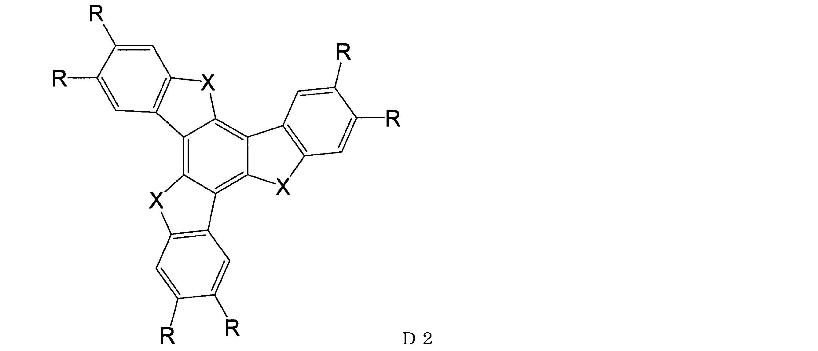
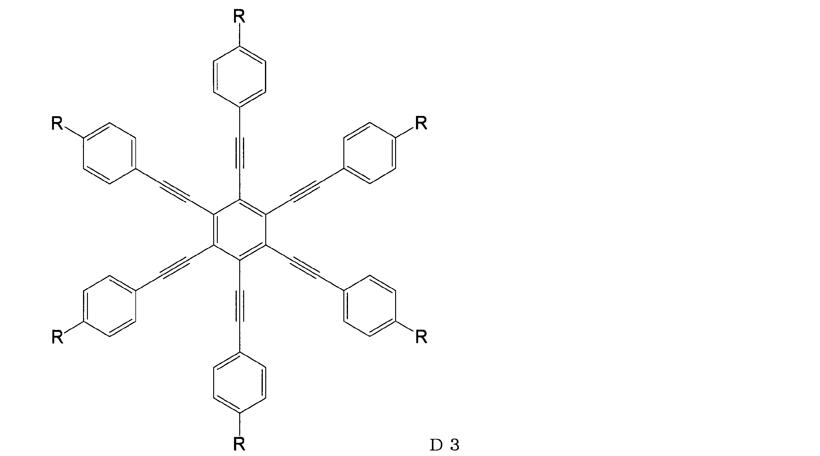
(|n2-n3|/|n2-n1|)≦0.2
であるものを、負の一軸性を有する層として実用に供しうる。また、ツイスティッドネマチック型液晶セルの視野角特性を大幅に改良しうる光学異方性層を得るためには、光学軸は、光学異方性層の面の法線方向からの傾きβが5°~60°であることが好ましく、10°~50°がより好ましく、20°~40°が最も好ましい。更光学異方性層は、50≦Re≦400(nm)の条件を満足することが好ましい。
これらの液晶化合物及び以下に説明する逆波長分散重合性液晶化合物は、1種類を単独で用いてもよく、2種類以上を任意の比率で組み合わせて用いてもよい。
重合性液晶化合物の一部又は全部として、逆波長分散重合性液晶化合物を用いうる。逆波長分散重合性液晶化合物を用いることにより、逆波長分散性を有する光学異方性層を容易に得ることができる。
逆波長分散重合性液晶化合物の例としては、下記式(I)で示される化合物(以下において「化合物(I)」という場合がある。)を挙げることができる。

R1の炭素数1~6のアルキル基としては、メチル基、エチル基、n-プロピル基、イソプロピル基、n-ブチル基、sec-ブチル基、t-ブチル基、n-ペンチル基、n-へキシル基等が挙げられる。
R1としては、水素原子又は炭素数1~4のアルキル基が好ましい。
炭素数1~20の二価の脂肪族基としては、炭素数1~20のアルキレン基、炭素数2~20のアルケニレン基等の鎖状構造を有する二価の脂肪族基;炭素数3~20のシクロアルカンジイル基、炭素数4~20のシクロアルケンジイル基、炭素数10~30の二価の脂環式縮合環基等の二価の脂肪族基;等が挙げられる。
前記脂肪族基に介在する基としては、-O-、-O-C(=O)-、-C(=O)-O-、-C(=O)-が好ましい。
該アルケニル基の炭素数としては、2~6が好ましい。Z1及びZ2のアルケニル基の置換基であるハロゲン原子としては、フッ素原子、塩素原子、臭素原子等が挙げられ、塩素原子が好ましい。
本発明において、「芳香環」は、Huckel則に従う広義の芳香族性を有する環状構造、すなわち、π電子を(4n+2)個有する環状共役構造、及びチオフェン、フラン、ベンゾチアゾール等に代表される、硫黄、酸素、窒素等のヘテロ原子の孤立電子対がπ電子系に関与して芳香族性を示すものを意味する。
なお、Axの炭素数2~30の有機基の「炭素数」は、置換基の炭素原子を含まない有機基全体の総炭素数を意味する(後述するAyにて同じである。)。
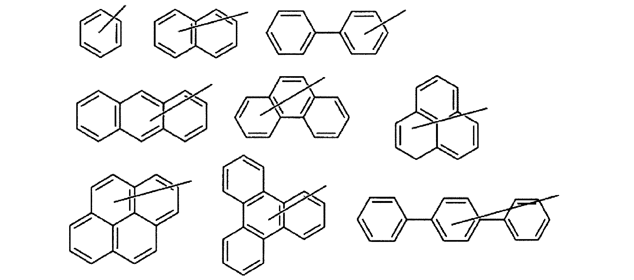



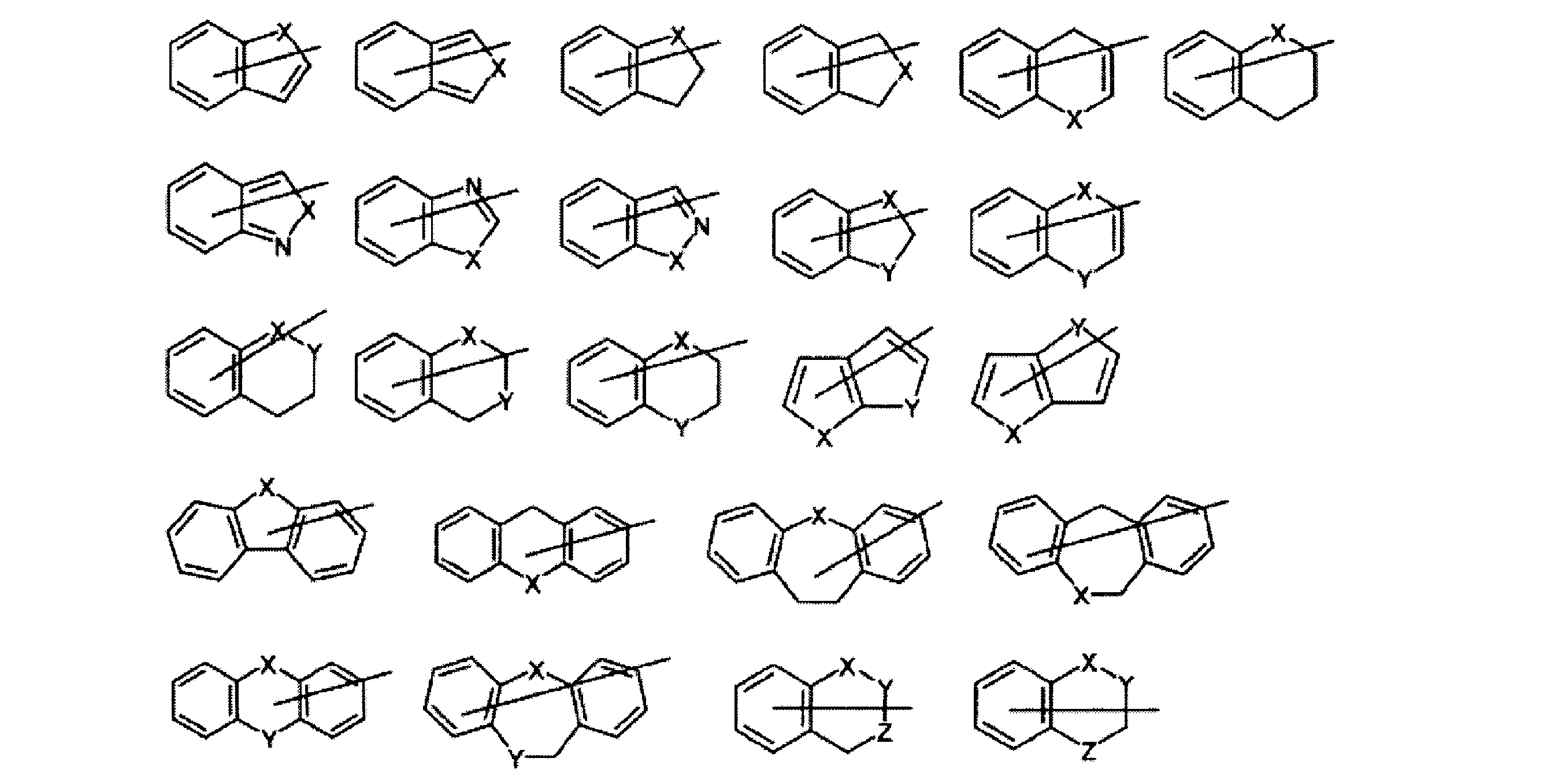

(3)芳香族炭化水素環基及び芳香族複素環基からなる群から選ばれる少なくとも一つの芳香環を有する、アルキル基
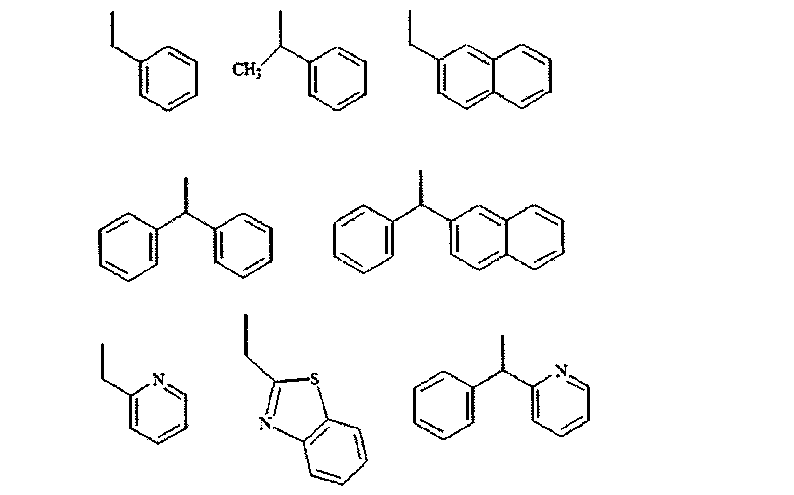


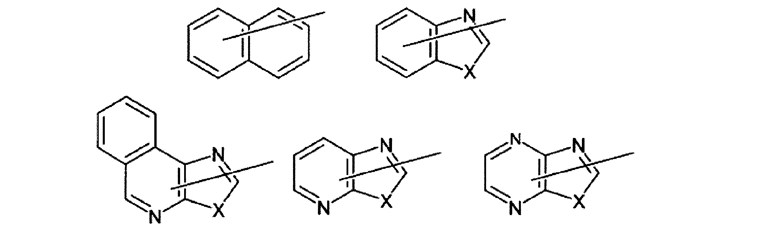
なお、Axの炭素数2~30の有機基の「炭素数」は、置換基の炭素原子を含まない有機基全体の総炭素数を意味する(後述するAyにて同じである。)。
置換基を有していてもよい炭素数2~20のアルケニル基の炭素数は、2~12であることが好ましい。
R4の、炭素数1~20のアルキル基、及び炭素数2~20のアルケニル基の具体例は、前記Ayの、炭素数1~20のアルキル基、炭素数2~20のアルケニル基の例として列記したものと同様のものが挙げられる。
Ayの、置換基を有していてもよい炭素数3~12のシクロアルキル基、置換基を有してもよい炭素数6~12の芳香族炭化水素基、置換基を有していてもよい炭素数3~9の芳香族複素環基の置換基としては、フッ素原子、炭素数1~6のアルキル基、炭素数1~6のアルコキシ基、シアノ基が好ましい。

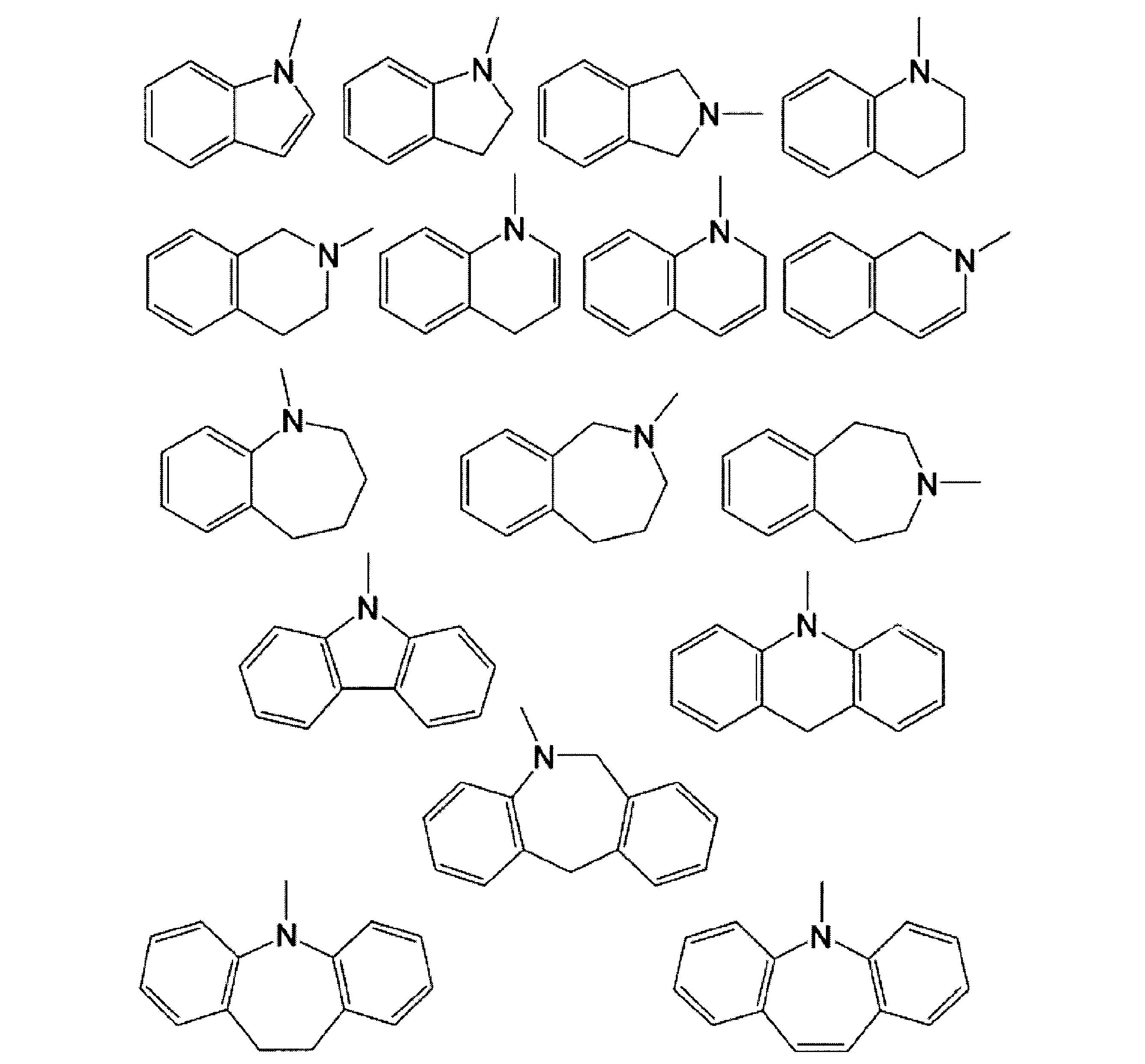
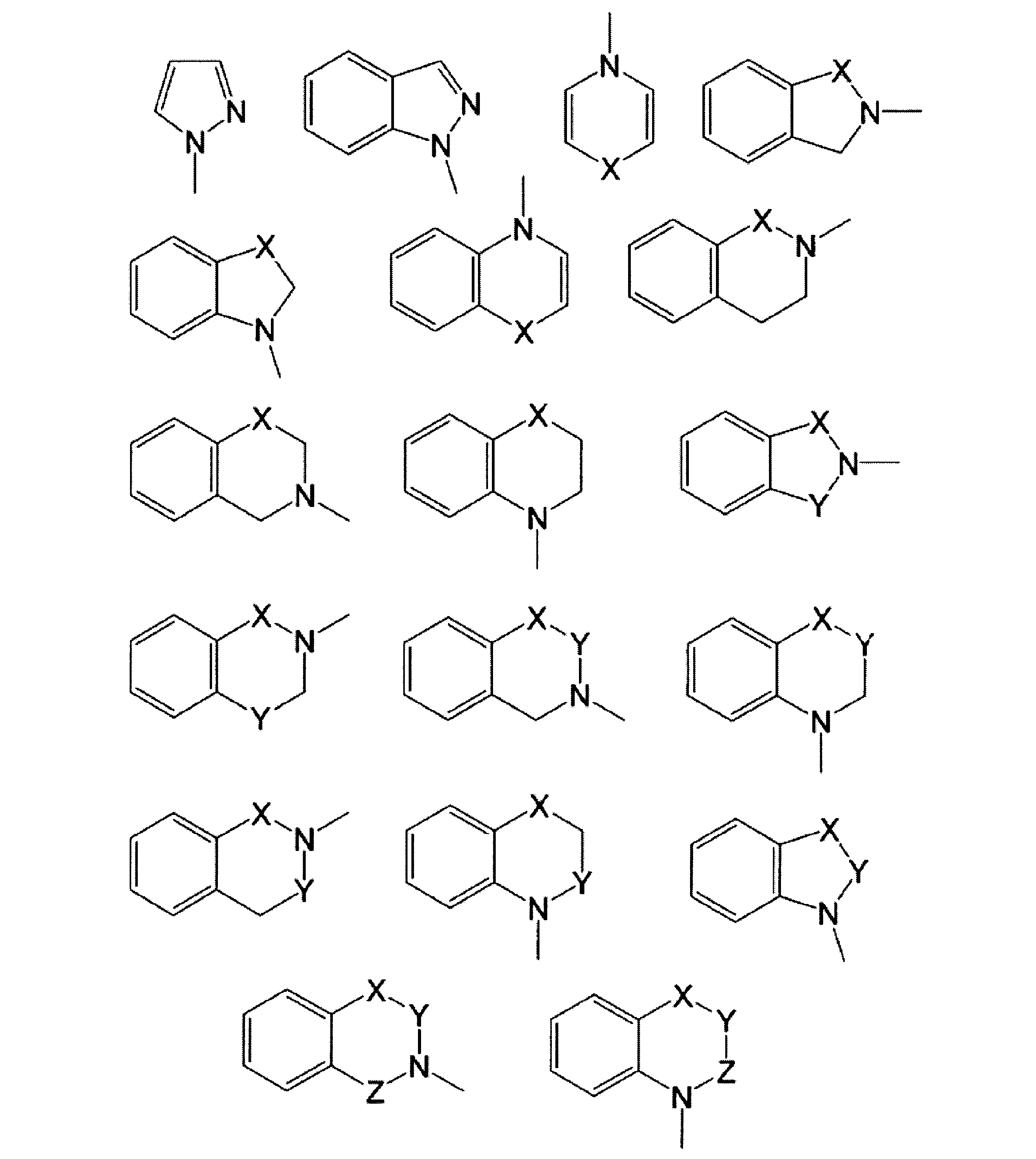
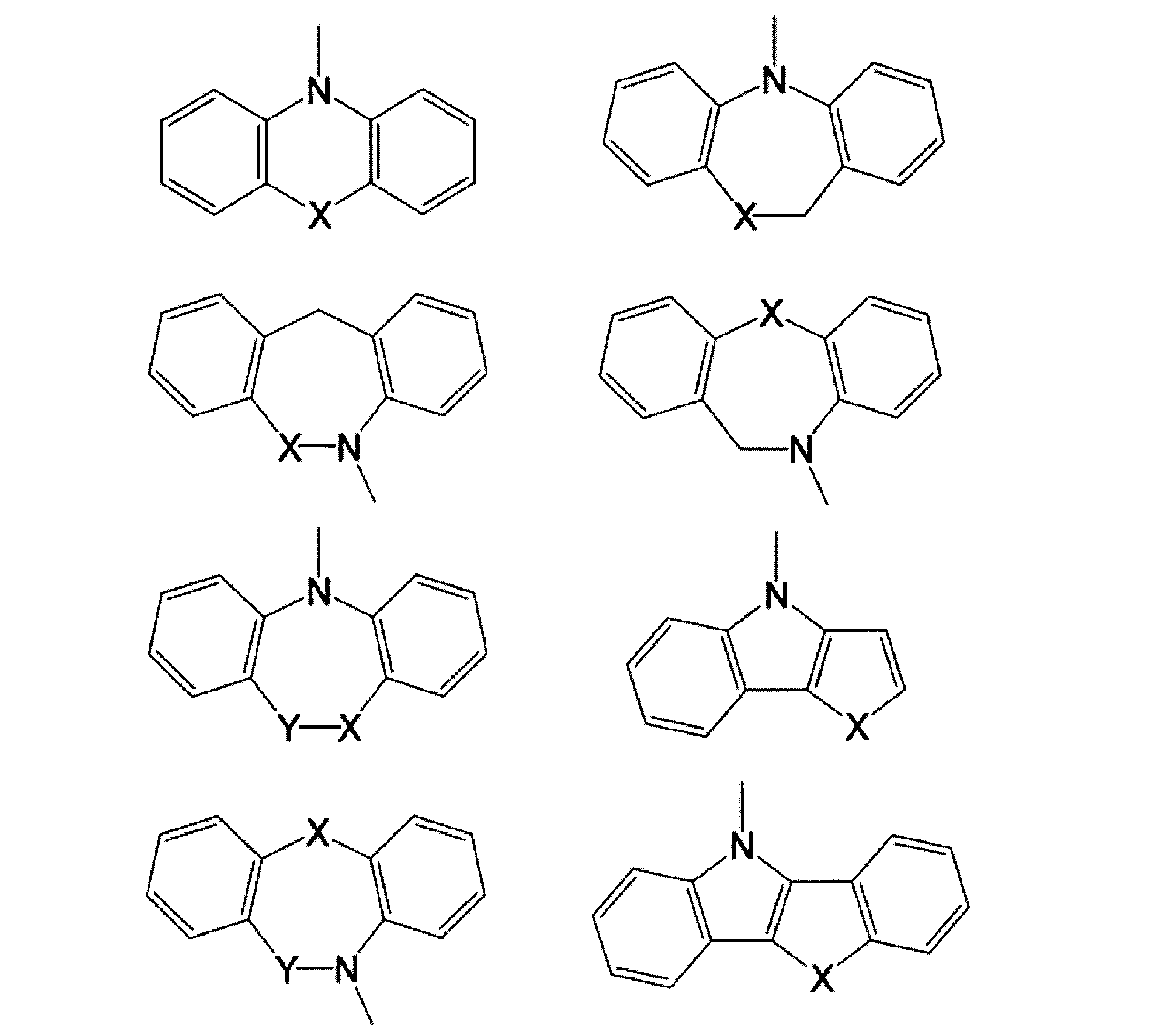
また、これらの環は置換基を有していてもよい。かかる置換基としては、Axが有する芳香環の置換基として例示したのと同様のものが挙げられる。
(α)Axが炭素数4~30の、芳香族炭化水素基又は芳香族複素環基であり、Ayが水素原子、炭素数3~8のシクロアルキル基、(ハロゲン原子、シアノ基、炭素数1~6のアルキル基、炭素数1~6のアルコキシ基、若しくは炭素数3~8のシクロアルキル基)を置換基として有していてもよい炭素数6~12の芳香族炭化水素基、(ハロゲン原子、炭素数1~6のアルキル基、炭素数1~6のアルコキシ基、シアノ基)を置換基として有していてもよい炭素数3~9の芳香族複素環基、置換基を有していてもよい炭素数1~20のアルキル基、置換基を有していてもよい炭素数1~20のアルケニル基、置換基を有していてもよい炭素数2~20のアルキニル基であり、当該置換基が、ハロゲン原子、シアノ基、炭素数1~20のアルコキシ基、炭素数1~12のアルコキシ基で置換された炭素数1~12のアルコキシ基、フェニル基、シクロヘキシル基、炭素数2~12の環状エーテル基、炭素数6~14のアリールオキシ基、水酸基、ベンゾジオキサニル基、ベンゼンスルホニル基、ベンゾイル基、-SR10のいずれかである組み合わせ、及び、
(β)AxとAyが一緒になって不飽和複素環又は不飽和炭素環を形成しているもの、
が挙げられる。ここで、R10は前記と同じ意味を表す。
(γ)Axが下記構造を有する基のいずれかであり、Ayが水素原子、炭素数3~8のシクロアルキル基、(ハロゲン原子、シアノ基、炭素数1~6のアルキル基、炭素数1~6のアルコキシ基、若しくは炭素数3~8のシクロアルキル基)を置換基として有していてもよい炭素数6~12の芳香族炭化水素基、(ハロゲン原子、炭素数1~6のアルキル基、炭素数1~6のアルコキシ基、シアノ基)を置換基として有していてもよい炭素数3~9の芳香族複素環基、置換基を有していてもよい炭素数1~20のアルキル基、置換基を有していてもよい炭素数1~20のアルケニル基、置換基を有していてもよい炭素数2~20のアルキニル基であり、当該置換基が、ハロゲン原子、シアノ基、炭素数1~20のアルコキシ基、炭素数1~12のアルコキシ基で置換された炭素数1~12のアルコキシ基、フェニル基、シクロヘキシル基、炭素数2~12の環状エーテル基、炭素数6~14のアリールオキシ基、水酸基、ベンゾジオキサニル基、ベンゼンスルホニル基、ベンゾイル基、-SR10のいずれかである組み合わせである。ここで、R10は前記と同じ意味を表す。

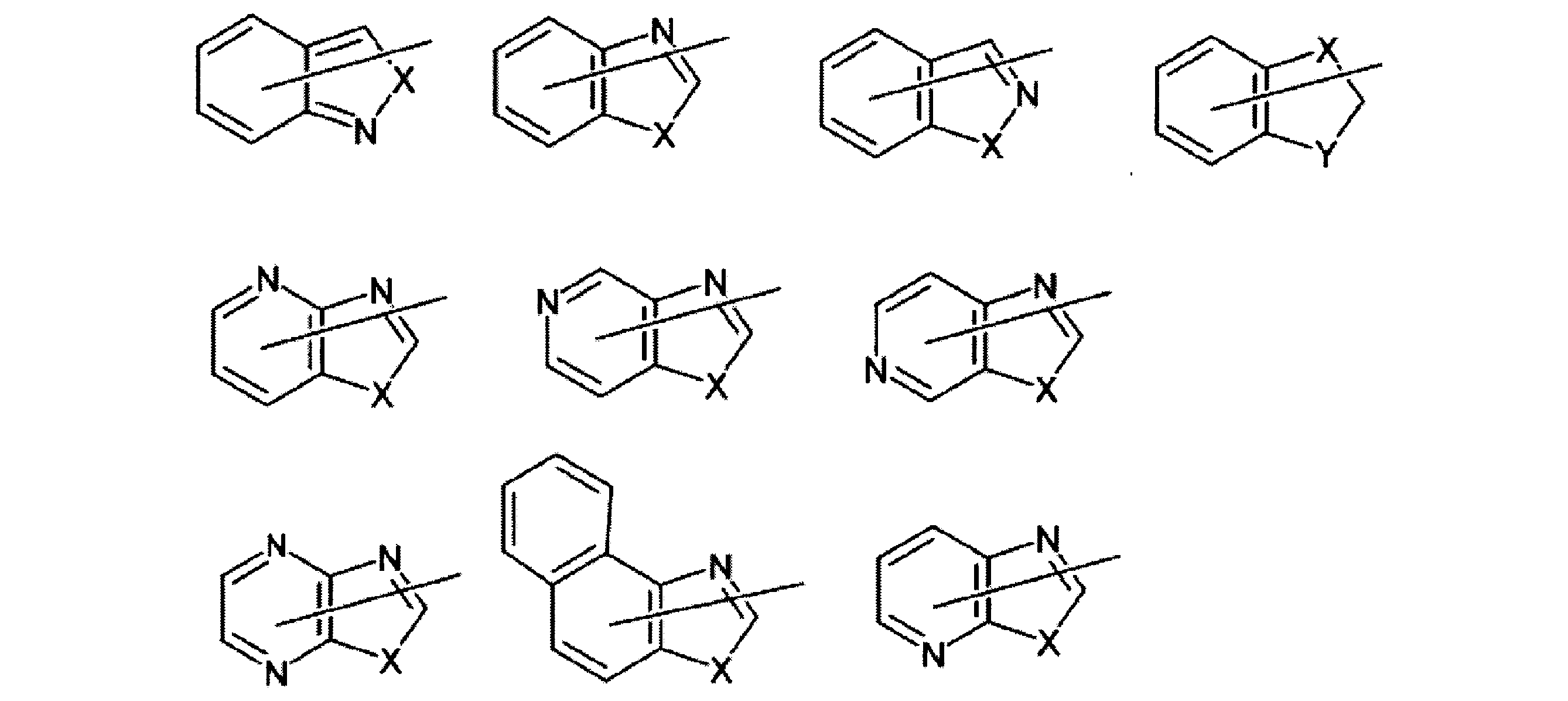
AxとAyの特に好ましい組み合わせとしては、
(δ)Axが下記構造を有する基のいずれかであり、Ayが水素原子、炭素数3~8のシクロアルキル基、(ハロゲン原子、シアノ基、炭素数1~6のアルキル基、炭素数1~6のアルコキシ基、若しくは炭素数3~8のシクロアルキル基)を置換基として有していてもよい炭素数6~12の芳香族炭化水素基、(ハロゲン原子、炭素数1~6のアルキル基、炭素数1~6のアルコキシ基、シアノ基)を置換基として有していてもよい炭素数3~9の芳香族複素環基、置換基を有していてもよい炭素数1~20のアルキル基、置換基を有していてもよい炭素数1~20のアルケニル基、置換基を有していてもよい炭素数2~20のアルキニル基であり、当該置換基が、ハロゲン原子、シアノ基、炭素数1~20のアルコキシ基、炭素数1~12のアルコキシ基で置換された炭素数1~12のアルコキシ基、フェニル基、シクロヘキシル基、炭素数2~12の環状エーテル基、炭素数6~14のアリールオキシ基、水酸基、ベンゾジオキサニル基、ベンゼンスルホニル基、ベンゾイル基、-SR10のいずれかである組合せである。下記式中、Xは前記と同じ意味を表す。ここで、R10は前記と同じ意味を表す。

なお、下記式においては、結合状態をより明確にすべく、置換基Y1、Y2を便宜上記載している(Y1、Y2は、前記と同じ意味を表す。以下にて同じ。)。

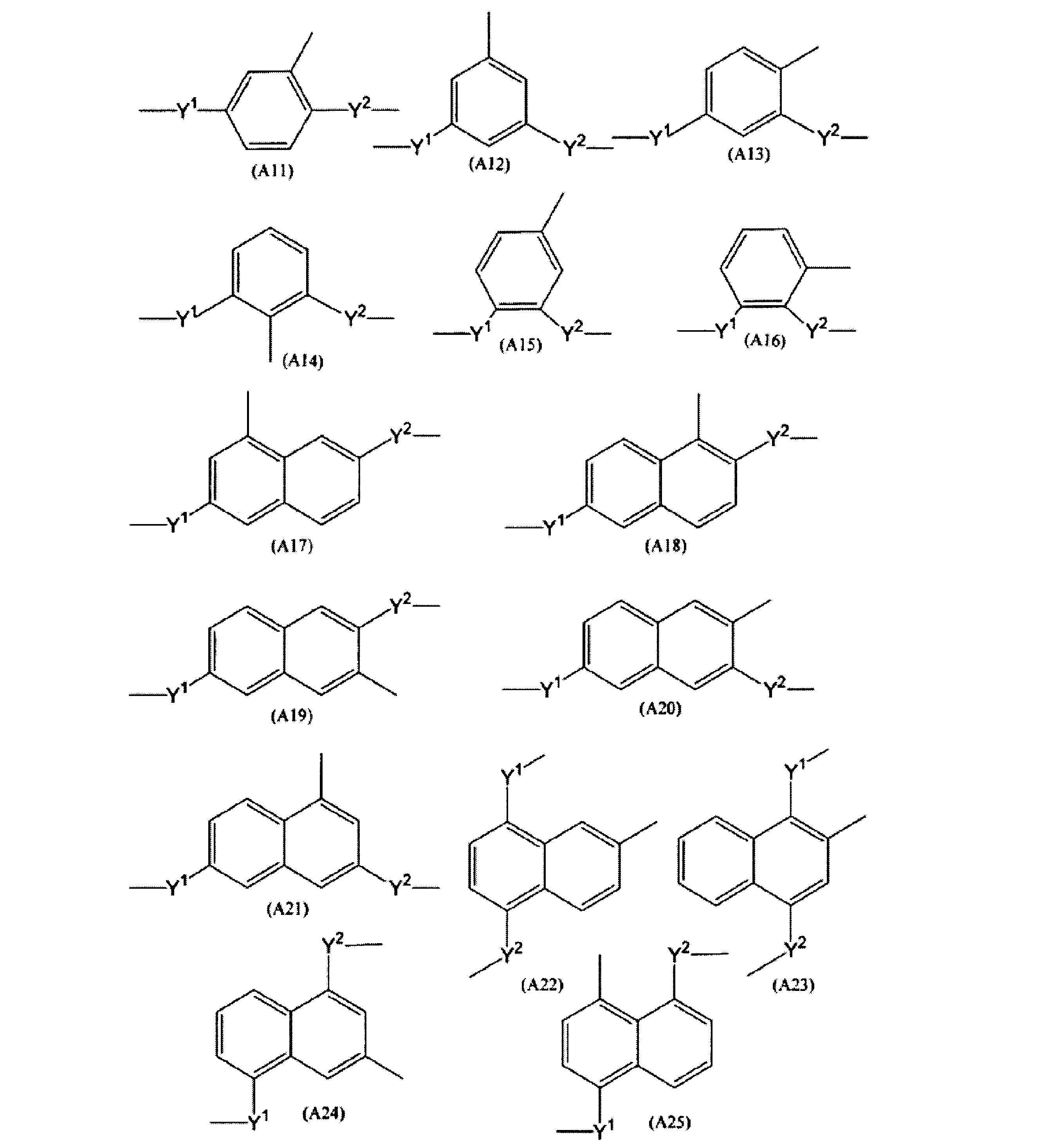
炭素数3~30の二価の脂環式炭化水素基としては、炭素数3~30のシクロアルカンジイル基、炭素数10~30の二価の脂環式縮合環基等が挙げられる。

前記炭素数3~30の二価の脂環式炭化水素基は、Y1、Y3(又はY2、Y4)と結合する炭素原子の立体配置の相違に基づく、シス型、トランス型の立体異性体が存在し得る。例えば、シクロヘキサン-1,4-ジイル基の場合には、下記に示すように、シス型の異性体(A32a)とトランス型の異性体(A32b)が存在し得る。

A4、A5の芳香族基は単環のものであっても、多環のものであってもよい。
A4、A5の好ましい具体例としては、下記のものが挙げられる。
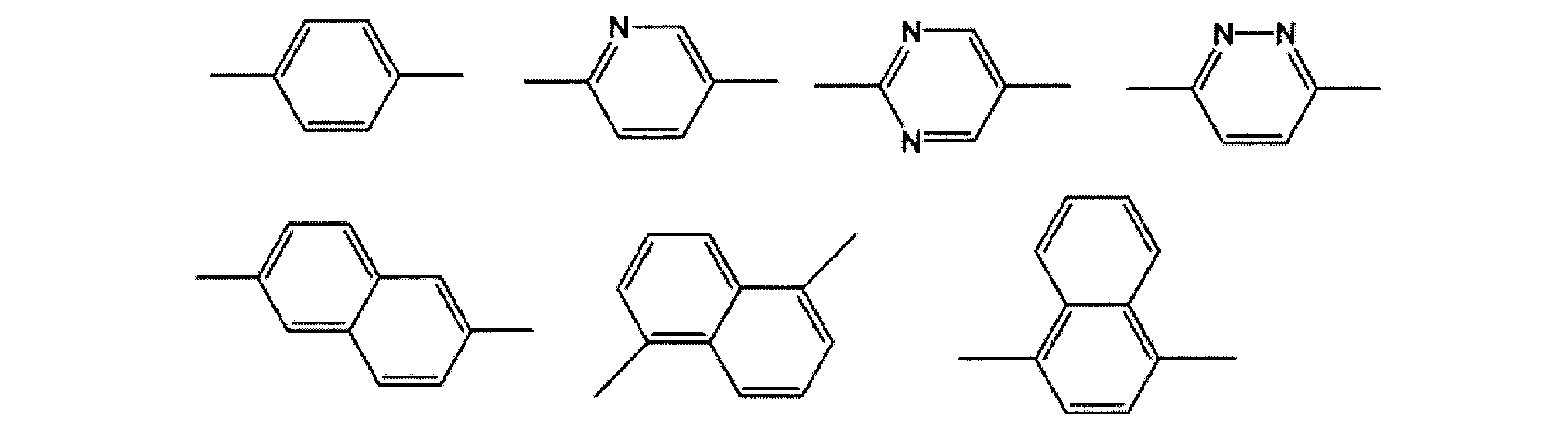

置換基を有していてもよい炭素数1~6のアルキル基としては、前記AXで例示したのと同様のものが挙げられる。
これらの中でも、Q1は、水素原子又は炭素数1~6のアルキル基が好ましく、水素原子及びメチル基がより好ましい。
組成物(A)が重合性液晶化合物として逆波長分散重合性液晶化合物を含有する場合、組成物(A)は、任意の成分として、重合性モノマー(a)を含有しうる。本願において、「重合性モノマー(a)」とは、重合能を有しモノマーとして働きうる化合物のうち、特に、逆波長分散重合性液晶化合物以外の化合物をいう。
重合性モノマー(a)としては、例えば、1分子当たり1以上の重合性基を有するものを用いうる。そのような重合性基を有することにより、光学異方性層の形成に際し重合を達成することができる。重合性モノマー(a)が1分子当たり2以上の重合性基を有する架橋性モノマーである場合、架橋的な重合を達成することができる。かかる重合性基の例としては、化合物(I)中の基Z1-Y7-及びZ2-Y8-と同様の基及びエポキシ基を挙げることができ、より具体的には例えば、アクリロイル基、メタクリロイル基、及びエポキシ基を挙げることができる。
ZM1-YM1-AM1-YM3-MM-YM4-AM2-YM2-ZM2 (M1)
YM1~YM4は独立に、化学的単結合、酸素、硫黄、-O-CO-、-CO-O-、-O-CO-O-、-CO-NRM-、-NRM-CO-、-O-CO-NRM-、-NRM-CO-O-または-NRM-CO-NRM-を表す。ここで基YM3およびYM4の中の少なくとも1個は、-O-CO-O-、-O-CO-NRM-、-NRM-CO-O-または-NRM-CO-NRM-を表す。
AM1及びAM2は独立に、2~30個のC原子を有するスペーサーを表わし、この場合炭素鎖には、エーテル官能基中の酸素、チオエーテル官能基中の硫黄または隣接していないイミノ基もしくはC1~C4-アルキルイミノ基が介在していてもよい。
MMは、重合性モノマー(a)のメソゲン基を表す。RMは、C1~C4-アルキルを表す。重合性モノマー(a)に2以上のRMが存在する場合、これらは同一であってもよく、異なっていてもよい。
ZM1及びZM2の例としては、下記式で表される基及びエポキシ基が挙げられる。
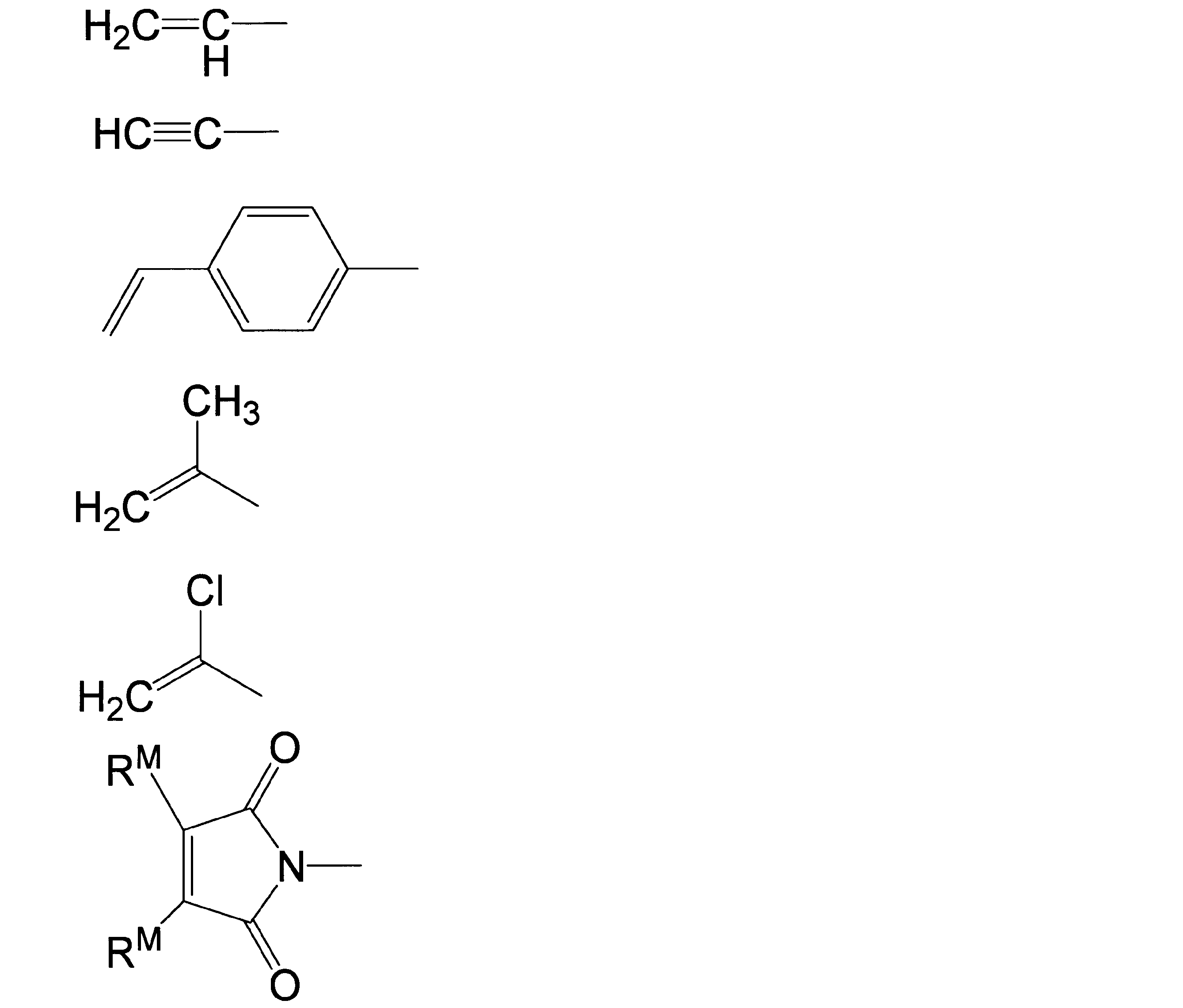

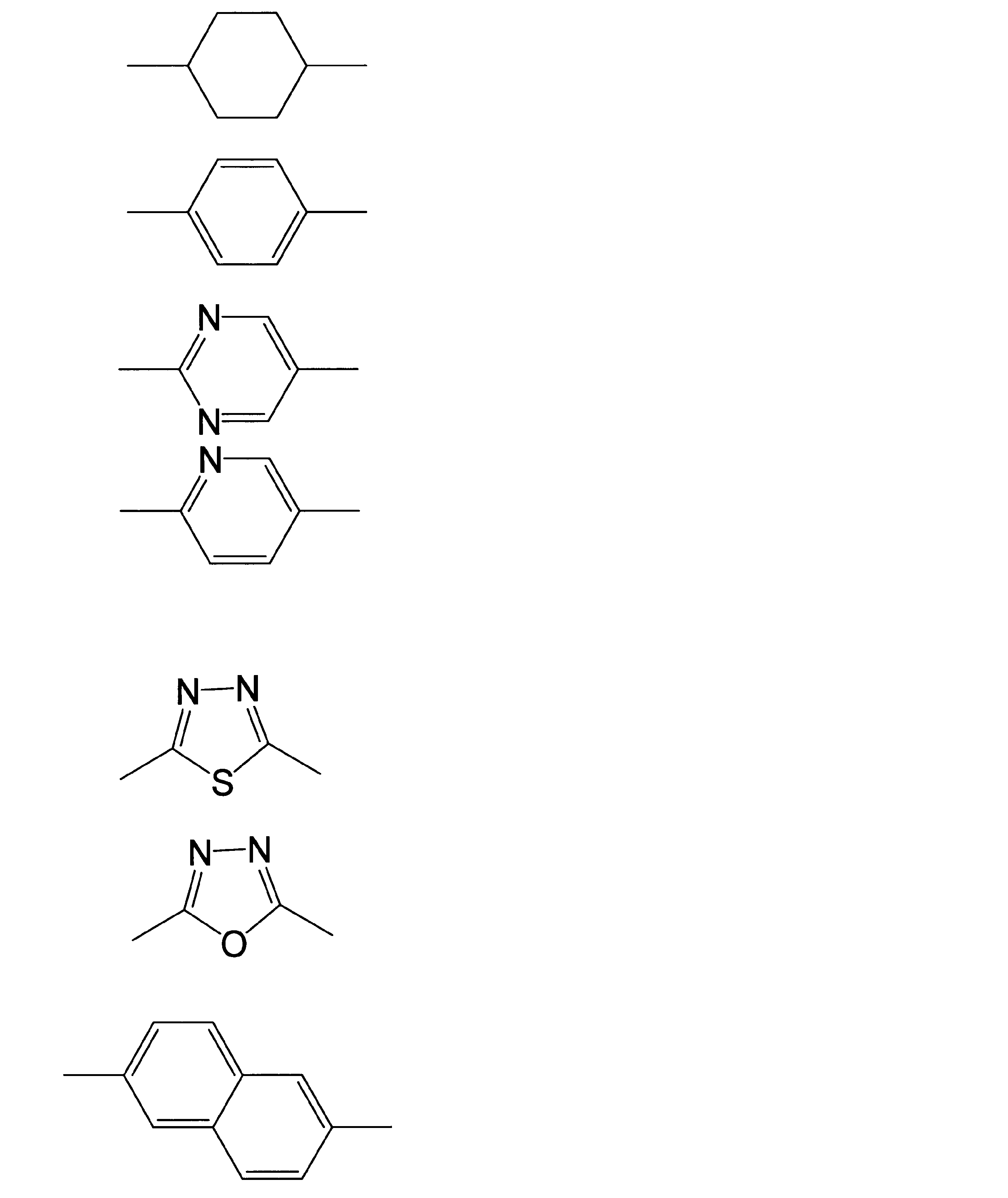
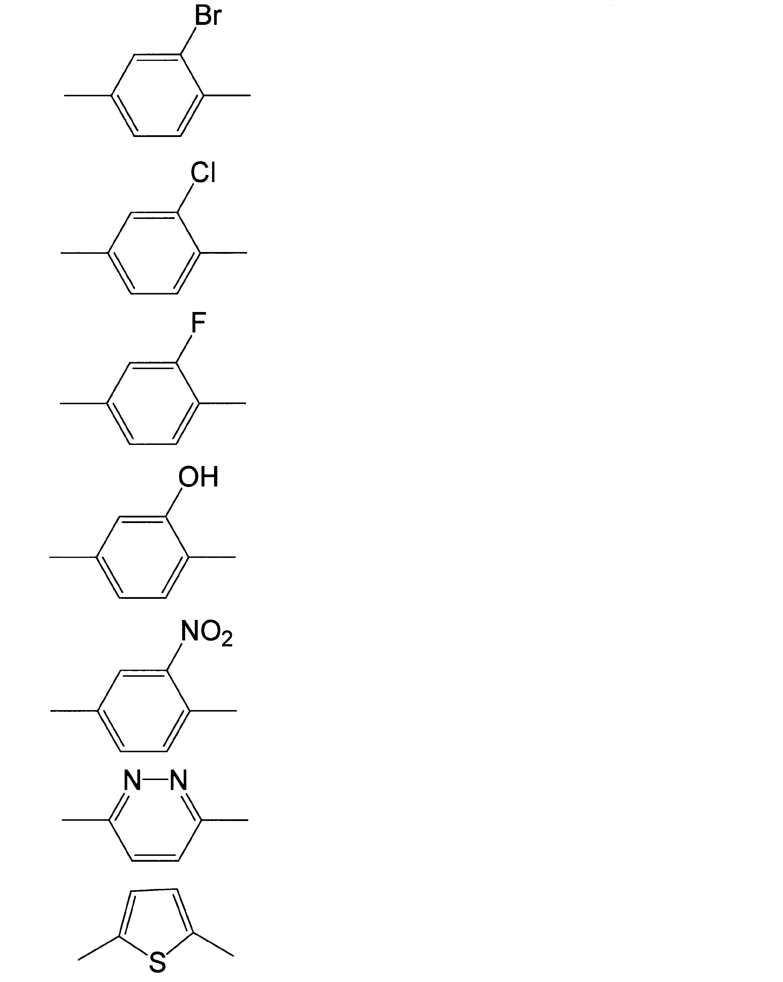
重合性モノマー(a)は、既知の製造方法により製造することができる。または、化合物(I)と類似の構造を持つものについては、化合物(I)の製造方法に準じて製造することができる。
組成物(A)は、重合性液晶化合物及び上に述べた任意の化合物(重合性モノマー(a)等)に加えて、必要に応じて、以下に例示するもの等の任意の成分を含みうる。
組成物(A)において、重合開始剤の配合割合は、重合性化合物100重量部に対し、通常、0.1~30重量部、好ましくは0.5~10重量部である。


本発明の光学補償シートは、前記本発明の複層フィルムから、光学異方性層を剥離し、これを長尺状の第二の基材に貼合してなる。
Rth=[{(nx+ny)/2}-nz](式中、nxは、基材フィルム面内の遅相軸方向の屈折率(面内の最大屈折率)であり、nyは、基材フィルム面内の遅相軸に垂直な方向の屈折率であり、nzは、基材フィルムの厚み方向の屈折率であり、dは、基材フィルムの厚み(nm)である。)
光学等方性の基材フィルムの材料の例としては、上に述べた第一の基材フィルムと同様のものの他にセルロースエステル等が挙げられる。そのような材料の長尺状フィルムを形成し、これを延伸せず、そのまま第二の基材として用いうる。第二の基材として、光学等方性の基材フィルムを備える光学補償シートは、そのまま、表示装置等の光学装置に組み込み、光学部材として用いうる。
本発明のλ/4波長板は、前記本発明の複層フィルムから、光学異方性層を剥離し、これを長尺状の第二の基材に貼合してなる。
本発明の円偏光板は、前記本発明のλ/4波長板を備える。
円偏光板(i):長尺状のλ/4波長板と、長尺状の直線偏光子とを貼合してなる円偏光板。
円偏光板(ii):長尺状のλ/4波長板と、長尺状のλ/2波長板と、長尺状の直線偏光子とを貼合してなる円偏光板。
・当該円偏光板を、そのある一方の面から観察すると、λ/2波長板の遅相軸の方向が、直線偏光子の吸収軸または透過軸の方向から時計周りに15°シフトし、且つλ/4波長板の遅相軸の方向が、直線偏光子の吸収軸または透過軸の方向から時計周りに75°シフトしている。
・当該円偏光板を、そのある一方の面から観察すると、λ/2波長板の遅相軸の方向が、直線偏光子の吸収軸または透過軸の方向から反時計周りに15°シフトし、且つλ/4波長板の遅相軸の方向が、直線偏光子の吸収軸または透過軸の方向から反時計周りに75°シフトしている。
以下の説明において、量を表す「%」及び「部」は、別に断らない限り重量基準である。また、以下に説明する操作は、別に断らない限り、常温及び常圧の条件において行った。
(A)第一の基材の表面張力
協和界面科学(株)製Drop Master DM500を使用し、各実施例及び比較例で調製した第一の基材をテーブルにセットし、表面張力測定用液として純水A3(JIS K0557)を使用し、液滴法により、光学異方性層を設ける側の表面の接触角測定を行った。
測定した接触角を式Iに代入することで、第一の基材の表面張力を求めた。
cosθ=0.0467・γS-1.508 式I
(θ:純水の接触角(°)、γS:第一の基材の表面張力(mN/m))
協和界面科学(株)製Drop Master DM500を使用し、各実施例及び比較例で調製した溶液状の液晶組成物を表面張力測定用液として、表面張力計を使用し、懸滴法により上記式IIを用いて液晶組成物液の表面張力を求めた。
γL=g・ρ・(de)2H-1 式II
(γL:液晶組成物の表面張力
g:重力加速度
ρ:液密度
de:最大液滴径
H-1:ds/deから求められる補正項
ds:液下端de上がった位置での径)
実施例及び比較例で得られた複層フィルムの光学異方性層を、転写し、接着剤(日東電工製、商品名「CS9621T」)を介して脂環式構造含有重合体樹脂のフィルム(ゼオノアフィルムZF14-050、株式会社オプテス製)に貼合した。これにより、(脂環式構造含有重合体樹脂のフィルム)/(粘着剤層)/(光学異方性層)の層構成を有する、光学補償シート又はλ/4波長板を作製し、これを、以下の評価に用いた。
光学補償シート又はλ/4波長板を、AxoScan(Axometrics社製)を用いて、測定波長550nmで測定し、配向状態を観察した。
光学補償シート又はλ/4波長板を、2枚の直線偏光子(偏光子及び検光子)の間に置いた。この際、前記の直線偏光子は、厚み方向から見て、互いの偏光透過軸が垂直になるように、向きを設定した。また、光学異方性層の遅相軸方向は、厚み方向から見て、直線偏光子の偏光透過軸と平行又は垂直になるように設定し、このサンプルを透過する光の透過率(クロスニコル透過率、波長550nm)を、日本分光社製の分光光度計「V7200」及び自動偏光フィルム測定装置「VAP-7070S」を用いて測定した。
ツイステッドネマチック型液晶セル(液晶の異常光と常光の屈折率の差と液晶セルのギャップサイズの積450nm、ねじれ角90゜)に装着された2枚の偏光板を液晶セルから剥離し、実施例1~3並びに比較例1、3、4、及び6で得た複層フィルムを用いて作製した光学補償シートを前記剥離した偏光板に装着し、視認者側から偏光板/光学補償シート/液晶セル/光学補償シート/偏光板の構成となるよう液晶セルに装着し、液晶セルを黒表示させ、以下の評価基準で評価した。ここで光学補償シートの脂環式構造含有重合体樹脂のフィルムが偏光板側となるように装着した。
良:白い光抜けが見られる面積が、全画面中10%未満。
不良:白い光抜けが見られる面積が、全画面中10%以上。
偏光フィルム(サンリッツ社製、商品名「HLC2-5618S」、厚さ180μm、短尺方向に対して90°の方向に吸収軸を有する)を用意した。この一方の面と、実施例4~6並びに比較例2、5及び7で得られた複層フィルムを用いて作製したλ/4波長板とを貼合した。貼合は粘着剤層(日東電工製、商品名「CS9621T」)を介して行った。これにより、(偏光子)/(粘着剤層)/(第二の基材)/(λ/4波長板)の層構成を有する円偏光板を得た。実施例7については、工程(7-6)で得られた円偏光板をそのまま用いた。
良:白い光抜けが見られる面積が、全画面中10%未満。
不良:白い光抜けが見られる面積が、全画面中10%以上。
(1-1.第一の基材の調製)
厚さ100μm、幅1330mmの長尺の脂環式構造含有重合体樹脂のフィルム(ゼオノアフィルムZF14-100、株式会社オプテス製)にコロナ処理(出力0.2kW、電極幅1600mm、処理速度20m/min)を施し、その後テンター延伸機に供給し、延伸温度145℃、延伸倍率1.5倍で斜め延伸した。これにより、延伸方向(短尺方向に対する方向)45°、コロナ処理された側の面の表面張力35.2mN/mの第一の基材を得た。
セルロースアセテートブチレート(コダックケミカル社製、商品名:CAB-531-1)6部、特開平9-95467を参照して合成した円盤状化合物D1(Rは、いずれも-O-C(=O)-Ph-O-C4H8-O-C(=O)-CH=CH2)100部、トリプロピレングリコールジアクリレート(東京化成社製)10部、光重合開始剤としてイルガキュア907(BASF製)2部及びメチルエチルケトン400部を混合し、液晶組成物を調製した。得られた液晶組成物について、表面張力を測定したところ、28.3mN/mであった。
(1-1)で得た第一の基材の、コロナ処理された側の面に、(1-2)で得た液晶組成物をバーコーターにより塗布し、液晶組成物の層を形成した。これを、140℃の加熱ゾーンに入れ加熱状態で2分間放置後、窒素雰囲気下、積算光量100mJ/cm2(照射強度10mW/cm2を照射時間10秒)以上の紫外線を照射して、紫外線照射を行うことにより架橋反応させた。これにより膜厚2.0μmの光学異方性層を形成し、(第一の基材)/(光学異方性層)の層構成を有する複層フィルムを得た。
得られた複層フィルムの光学異方性層について、遅相軸と短尺方向とがなす角度の測定、クロスニコル透過率の測定、及び液晶表示装置での評価を行った。結果を表1にまとめて示す。得られた光学異方性層の配向状態は、短尺方向に対して45°のハイブリッド配向であり、面内方向のレターデーションReは30nmであった。
(2-1.第一の基材の調製)
厚さ100μm、幅1330mmの長尺の、脂環式構造含有重合体樹脂のフィルム(ゼオノアフィルムZF14-100、株式会社オプテス製)にコロナ処理(出力0.2kW、電極幅1600mm、処理速度20m/min)を施した。このコロナ処理された面に、ポリビニルアルコール(商品名「PVA226」、株式会社クラレ製)の5wt%水溶液を、#4バーにて塗布し、120℃で5分間乾燥し、ポリビニルアルコールの膜を形成し、(ポリビニルアルコール層)/(脂環式構造含有重合体樹脂のフィルム)の層構成を有する延伸前基材を得た。これをテンター延伸機に供給し、延伸温度145℃、延伸倍率1.5倍で斜め延伸した。これにより、延伸方向(短尺方向に対する方向)45°、ポリビニルアルコール層側の表面の表面張力44.4mN/mの第一の基材を得た。配向膜の厚みは0.2μmであった。
(2-1)で得た第一の基材の、配向膜側の面に、実施例1の(1-2)で得た液晶組成物をバーコーターにより塗布し、液晶組成物の層を形成した。これを、140℃の加熱ゾーンに入れ加熱状態で2分間放置後、紫外線照射を行うことにより架橋反応させた。これにより膜厚2.0μmの光学異方性層を形成し、(第一の基材)/(光学異方性層)の層構成を有する複層フィルムを得た。
得られた複層フィルムの光学異方性層について、遅相軸と短尺方向とがなす角度の測定、クロスニコル透過率の測定、及び液晶表示装置での評価を行った。結果を表1にまとめて示す。得られた光学異方性層の配向状態は、短尺方向に対して45°のハイブリッド配向であり、面内方向のレターデーションReは35nmであった。
(3-1.第一の基材の調製)
厚さ80μm、幅1330mmの長尺のTACフィルム(フジタックT-80)を、40℃のアルカリ温水溶液(0.1MのNaOH水溶液)中に4分間浸漬させた後、水洗し、乾燥し、ケン化TACフィルムを得た。これをテンター延伸機に供給し、延伸温度185℃、延伸倍率1.8倍で斜め延伸した。これにより、延伸方向(短尺方向に対する方向)45°、表面張力37.4mN/mの第一の基材を得た。
(3-1)で得た第一の基材の一方の面に、実施例1の(1-2)で得た液晶組成物をバーコーターにより塗布し、液晶組成物の層を形成した。これを、140℃の加熱ゾーンに入れ加熱状態で2分間放置後、紫外線照射を行うことにより架橋反応させた。これにより膜厚2.0μmの光学異方性層を形成し、(第一の基材)/(光学異方性層)の層構成を有する複層フィルムを得た。得られた光学異方性層の配向状態は、短尺方向に対して45°のハイブリッド配向であった。
得られた複層フィルムの光学異方性層について、遅相軸と短尺方向とがなす角度の測定、クロスニコル透過率の測定、及び液晶表示装置での評価を行った。結果を表1にまとめて示す。得られた光学異方性層の配向状態は、短尺方向に対して45°のハイブリッド配向であり、面内方向のレターデーションReは40nmであった。
(4-1.液晶組成物の調製)
式(B1)で表される逆波長分散重合性液晶化合物21.25部、界面活性剤(商品名「サーフロンS420」、AGCセイミケミカル社製)0.11部、重合開始剤(商品名「イルガキュア379」、BASF社製)0.64部、及び溶媒(シクロペンタノン、日本ゼオン株式会社製)78.00部を混合し、液晶組成物を調製した。得られた液晶組成物について、表面張力を測定したところ、33.4mN/mであった。
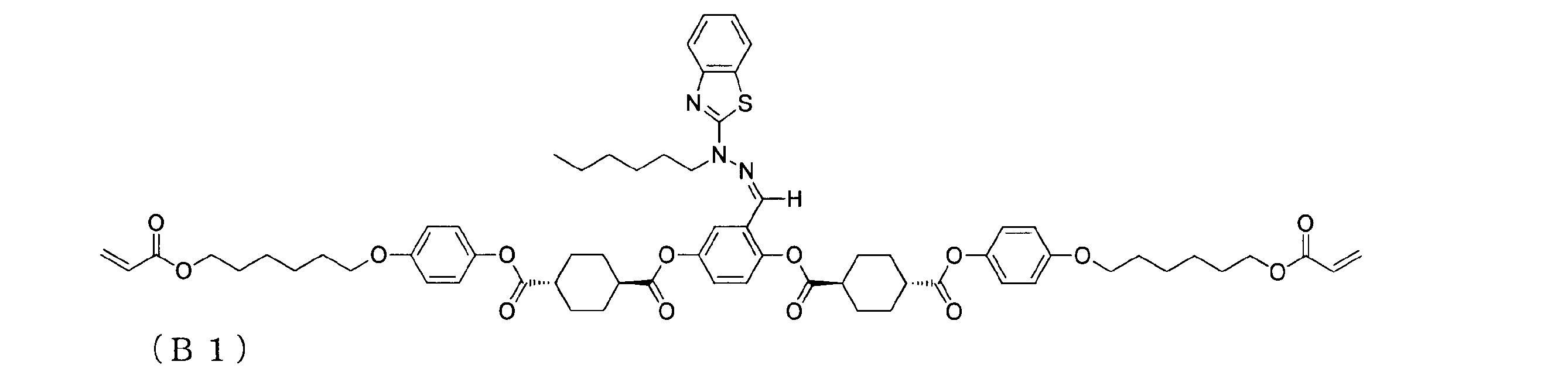
実施例1の(1-1)で得た第一の基材の、コロナ処理された側の面に、(4-1)で得た液晶組成物をダイコーターにより塗布し、液晶組成物の層を形成した。これを、110℃で2.5分間配向処理した。その後、窒素雰囲気下で、液晶組成物の層に、積算光量100mJ/cm2(照射強度10mW/cm2を照射時間10秒)以上の紫外線を照射して、液晶組成物中の重合性液晶化合物を重合させて、硬化液晶分子を形成した。これにより、乾燥膜厚2.3μmの光学異方性層を得て、(第一の基材)/(光学異方性層)の層構成を有する複層フィルムを得た。
得られた複層フィルムの光学異方性層について、遅相軸と短尺方向とがなす角度の測定、クロスニコル透過率の測定、及びOLEDでの評価を行った。結果を表1にまとめて示す。得られた光学異方性層の配向状態は、短尺方向に対して45°のホモジニアス配向であり、面内方向のレターデーションReは145nmであった。
第一の基材として、実施例1の(1-1)で得たものに代えて、実施例2の(2-1)で得たもの(実施例5)、又は実施例3の(3-1)で得たもの(実施例6)を用いた他は、実施例4と同様にして、複層フィルムを得て評価した。第一の基材のどちらの面に液晶組成物を塗布するかについては、実施例2及び3と同様とした。結果を表1にまとめて示す。得られた光学異方性層の配向状態は、実施例5及び6いずれも、短尺方向に対して45°のホモジニアス配向であり、面内方向のレターデーションReは143nm(実施例5)、及び145nm(実施例6)であった。
(7-1.第一の基材(75)の調製)
延伸方向を変更し、且つ延伸倍率を2.5倍に変更した他は、実施例2の(2-1)と同様にして、延伸方向(短尺方向に対する方向)75°、表面張力44.4mN/mの第一の基材(75)を得た。
延伸方向を変更した他は、実施例2の(2-1)と同様にして、延伸方向(短尺方向に対する方向)15°、表面張力44.4mN/mの第一の基材を得た。
重合性液晶化合物(商品名「LC242」BASF社製、式(A1)で示される化合物)24.15部、界面活性剤(商品名「フタージェントFTX-209F」、ネオス社製)0.12部、重合開始剤(商品名「イルガキュア379」、BASF社製)0.73重量部、及び溶媒(メチルエチルケトン)75.00部を混合し、液晶組成物を調製した。得られた液晶組成物について、表面張力を測定したところ、19.0mN/mであった。

(7-1)で得た第一の基材(75)の、配向膜側の面に、(7-3)で得た液晶組成物をバーコーターにより塗布し、液晶組成物の層を形成した。液晶組成物の層は、配向膜上において、細かいハジキに基づくムラが発生していた。これを、110℃で2.5分間配向処理した。その後、窒素雰囲気下で、液晶組成物の層に、積算照度100mJ/cm2(照射強度10mW/cm2を照射時間10秒)以上の紫外線を照射して、液晶組成物中の重合性液晶化合物を重合させて、硬化液晶分子を形成した。これにより、乾燥膜厚4.5μmの光学異方性層を得て、(第一の基材)/(光学異方性層)の層構成を有する複層フィルム(75)を得た。
(7-2)で得た第一の基材(15)の、配向膜側の面に、(7-3)で得た液晶組成物をバーコーターにより塗布し、液晶組成物の層を形成した。液晶組成物の層は、配向膜上において、細かいハジキに基づくムラが発生していた。これを、110℃で2.5分間配向処理した。その後、窒素雰囲気下で、液晶組成物の層に、積算照度100mJ/cm2(照射強度10mW/cm2を照射時間10秒)以上の紫外線を照射して、液晶組成物中の重合性液晶化合物を重合させて、硬化液晶分子を形成した。これにより、乾燥膜厚2.1μmの、ホモジニアス配向した光学異方性層を得て、(第一の基材)/(光学異方性層)の層構成を有する複層フィルム(15)を得た。
(7-4)で得た複層フィルム(75)の光学異方性層をλ/2波長板として用い、(7-5)で得た複層フィルム(15)の光学異方性層をλ/4波長板として用い、円偏光板を製造した。
まず、長尺の直線偏光子として、偏光フィルム(サンリッツ社製、商品名「HLC2-5618S」、厚さ180μm、短尺方向に対して90°の方向に吸収軸を有する)を用意した。この一方の面と、複層フィルム(75)の光学異方性層(即ちλ/2波長板)側の面とを貼合した。貼合は粘着剤層(日東電工製、商品名「CS9621T」)を介して行った。これにより、(偏光子)/(粘着剤層)/(λ/2波長板)/(第一の基材)の層構成を有する積層体(7-i)を得た。
次に、積層体(7-i)から、第一の基材を剥離し、(偏光子)/(粘着剤層)/(λ/2波長板)の層構成を有する積層体(7-ii)を得た。
次に、積層体(7-ii)のλ/2波長板側の面と、複層フィルム(15)の光学異方性層(即ちλ/4波長板)側の面とを貼合した。貼合は粘着剤層(日東電工製、商品名「CS9621T」)を介して行った。これにより、(偏光子)/(粘着剤層)/(λ/2波長板)/(粘着剤層)/(λ/4波長板)/(第一の基材)の層構成を有する積層体(7-iii)を得た。
次に、積層体(7-iii)から、第一の基材を剥離し、(偏光子)/(粘着剤層)/(λ/2波長板)/(粘着剤層)/(λ/4波長板)の層構成を有する円偏光板を得た。
これらの貼合及び剥離の操作は、いずれもロールツーロールにて連続的に行なった。したがって、貼合の操作は、いずれも長尺のフィルムの長尺方向を揃えた状態で行った。
得られた円偏光板の構成要素の光学軸は、図3に示す角度関係を有していた。即ち、偏光子304側の面から円偏光板300を観察した場合において、偏光板の吸収軸A34は、短尺方向A31と90°の角度をなしていた。λ/2波長板303の遅相軸A33は、短尺方向A31から時計周りにθ33=75°シフトし、且つ、λ/4波長板302の遅相軸A32は、短尺方向A31から時計周りにθ32=15°シフトしていた。
得られた複層フィルム(75)及び複層フィルム(15)の光学異方性層について、遅相軸と短尺方向とがなす角度の測定、及びクロスニコル透過率の測定を行った。結果を表1にまとめて示す。複層フィルム(75)の光学異方性層の配向状態は、短尺方向に対して75°のホモジニアス配向であり、複層フィルム(15)の光学異方性層の配向状態は、短尺方向に対して15°のホモジニアス配向であった。複層フィルム(75)及び複層フィルム(15)の光学異方性層のいずれにも、実用上問題無いものの、細かいハジキに基づくムラが存在した。複層フィルム(75)の光学異方性層の面内方向のレターデーションReは275nmであった。複層フィルム(15)の光学異方性層の面内方向のレターデーションReは143nmであった。
また(7-6)で得られた円偏光板について、OLEDでの評価を行った。評価に際し、図3に示す通り、円偏光板300を、発光パネル301上に、偏光板304が出光面側となるよう載置した。結果をまとめて表1に示す。
(8-1.第一の基材の調製)
実施例1と同様にして、第一の基材を得た。
重合性液晶化合物(実施例7で用いたものと同じ、式(A1)で示される化合物)68部、式(C1)で示される化合物29部、光重合開始剤としてイルガキュア184(BASF製)3部及びメチルエチルケトン400部を混合し、液晶組成物を調製した。得られた液晶組成物について、表面張力を測定したところ、25mN/mであった。

(8-1)で得た第一の基材の、コロナ処理された側の面に、(8-2)で得た液晶組成物をバーコーターにより塗布し、液晶組成物の層を形成した。これを、80℃の加熱ゾーンに入れ加熱状態で2分間放置後、窒素雰囲気下、積算光量100mJ/cm2(照射強度10mW/cm2を照射時間10秒)以上の紫外線を照射して、紫外線照射を行うことにより架橋反応させた。これにより膜厚2.0μmの光学異方性層を形成し、(第一の基材)/(光学異方性層)の層構成を有する複層フィルムを得た。
得られた複層フィルムの光学異方性層について、遅相軸と短尺方向とがなす角度の測定、クロスニコル透過率の測定、及び液晶表示装置での評価を行った。結果を表1にまとめて示す。得られた光学異方性層の配向状態は、短尺方向に対して45°のハイブリッド配向であり、面内方向のレターデーションReは28nmであった。
(1-1)の第一の基材の調製においてコロナ処理を行わなかった他は、実施例1と同様(比較例1)又は実施例4と同様(比較例2)にして、複層フィルムを得て評価した。コロナ処理を行わなかった第一の基材の表面の表面張力は34.0mN/mであった。結果を表2にまとめて示す。得られた光学異方性層の配向状態は、比較例1では無配向であり、比較例2では短尺方向に対して45°のホモジニアス配向であり、光学異方性層の面内方向のレターデーションReは139nmであった。
(2-1)の第一の基材の調製において、ポリビニルアルコールを、ポリビニルアルコール(商品名「ゴーセファイマーZ200」、日本合成化学社製)に変更した他は、実施例2と同様にして、複層フィルムを得て評価した。第一の基材の配向膜側の表面の表面張力は50.2mN/mであった。結果を表2にまとめて示す。得られた光学異方性層の配向状態は、短尺方向に対して概ね45°のハイブリッド配向であったが、面内白化が見られており、配向方向が不均一で、不良な配向であった。光学異方性層の面内方向のレターデーションReは50nmであった。
(C4-1.第一の基材の調製)
厚さ100μm、幅1330mmの長尺の、脂環式構造含有重合体樹脂のフィルム(ゼオノアフィルムZF14-100、株式会社オプテス製)に、(コロナ処理及び延伸を施さずに)、短尺方向に対して45°の方向にラビング処理を施した。これにより、ラビング処理された側の面の表面張力31.7mN/mの第一の基材を得た。
第一の基材として、(1-1)で得たものに代えて、(C4-1)で得たものを用い、ラビング処理された側の面に光学異方性層の形成を行った他は、実施例1と同様(比較例4)又は実施例4と同様(比較例5)にして、複層フィルムを得て評価した。結果を表2にまとめて示す。得られた光学異方性層の配向状態は、比較例4では短尺方向に対して45°のハイブリッド配向であり、比較例5では短尺方向に対して45°のホモジニアス配向であった。光学異方性層の面内方向のレターデーションReは30nm(比較例4)及び145nm(比較例5)であった。
TACフィルムをケン化しなかった他は、実施例3と同様(比較例6)又は実施例6と同様(比較例7)にして、複層フィルムを得て評価した。ケン化しないTACフィルムの表面の表面張力は55.0mN/mであった。結果を表2にまとめて示す。得られた光学異方性層の配向状態は、比較例6では無配向であり、比較例7では短尺方向に対して45°のホモジニアス配向であり、光学異方性層の面内方向のレターデーションReは139nmであった。


21:第一の基材の延伸による配向方向
22:極角0°方向
304:偏光子
300:円偏光板
A34:偏光板の吸収軸
A31:短尺方向
303:λ/2波長板
A33:遅相軸
302:λ/4波長板
A32:遅相軸
401:細管
402:液滴
Claims (12)
- 長尺状の第一の基材と、前記第一の基材の表面に直接設けられた、硬化液晶分子を含む光学異方性層とを備える複層フィルムであって、
前記第一の基材の前記表面は、その表面張力が35~45mN/mであり、且つ延伸による配向規制力を保有し、
前記光学異方性層が、前記第一の基材の延伸による配向方向と略同一方向に沿った遅相軸を有する、複層フィルム。 - 前記第一の基材が、複数の層からなる、請求項1に記載の複層フィルム。
- 前記硬化液晶分子が、円盤状液晶化合物の硬化物である、請求項1又は2に記載の複層フィルム。
- 前記硬化液晶分子が、棒状液晶化合物の硬化物である、請求項1又は2に記載の複層フィルム。
- 請求項1~4のいずれか1項に記載の複層フィルムの製造方法であって、
硬化性液晶化合物を含む液晶組成物を、長尺状の第一の基材上に塗布し、液晶組成物の層を形成し、
前記液晶組成物の層における硬化性液晶化合物を前記第一の基材の延伸による配向方向と略同一方向に沿ってホモジニアス配向又はハイブリッド配向させ、
前記硬化性液晶化合物を重合させ、硬化液晶分子を形成する
ことを含む製造方法。 - 前記液晶組成物が、表面張力20~35mN/mの液体である、請求項5に記載の製造方法。
- 請求項1、2、又は3に記載の複層フィルムから光学異方性層を剥離し、
前記光学異方性層を、第二の基材に貼合してなる、光学補償シート。 - 請求項1、2、又は4に記載の複層フィルムから、光学異方性層を剥離し、
前記光学異方性層を、第二の基材に貼合してなる、λ/4波長板。 - 請求項7に記載の光学補償シートを備える偏光板。
- 請求項8に記載のλ/4波長板を備える円偏光板。
- 請求項9に記載の偏光板を備える液晶表示装置。
- 請求項10に記載の円偏光板を備える有機エレクトロルミネッセンス表示装置。
Priority Applications (4)
| Application Number | Priority Date | Filing Date | Title |
|---|---|---|---|
| JP2016572132A JP6790836B2 (ja) | 2015-01-30 | 2016-01-28 | 複層フィルム、その用途、及び製造方法 |
| US15/544,984 US10712484B2 (en) | 2015-01-30 | 2016-01-28 | Multilayer film, use thereof, and production method thereof |
| CN201680005890.2A CN107209310B (zh) | 2015-01-30 | 2016-01-28 | 多层膜、其用途以及制造方法 |
| KR1020177019883A KR102535200B1 (ko) | 2015-01-30 | 2016-01-28 | 복층 필름, 그 용도 및 제조 방법 |
Applications Claiming Priority (2)
| Application Number | Priority Date | Filing Date | Title |
|---|---|---|---|
| JP2015017335 | 2015-01-30 | ||
| JP2015-017335 | 2015-01-30 |
Publications (1)
| Publication Number | Publication Date |
|---|---|
| WO2016121856A1 true WO2016121856A1 (ja) | 2016-08-04 |
Family
ID=56543461
Family Applications (1)
| Application Number | Title | Priority Date | Filing Date |
|---|---|---|---|
| PCT/JP2016/052456 Ceased WO2016121856A1 (ja) | 2015-01-30 | 2016-01-28 | 複層フィルム、その用途、及び製造方法 |
Country Status (6)
| Country | Link |
|---|---|
| US (1) | US10712484B2 (ja) |
| JP (2) | JP6790836B2 (ja) |
| KR (1) | KR102535200B1 (ja) |
| CN (1) | CN107209310B (ja) |
| TW (1) | TWI672361B (ja) |
| WO (1) | WO2016121856A1 (ja) |
Cited By (7)
| Publication number | Priority date | Publication date | Assignee | Title |
|---|---|---|---|---|
| WO2019116991A1 (ja) * | 2017-12-12 | 2019-06-20 | 日本ゼオン株式会社 | 液晶配向層及びその製造方法、光学フィルム及びその製造方法、1/4波長板、偏光板並びに有機エレクトロルミネッセンス表示パネル |
| CN110573916A (zh) * | 2017-04-20 | 2019-12-13 | 株式会社Lg化学 | 用于抗反射的滤光器和有机发光器件 |
| KR20210143226A (ko) | 2019-03-27 | 2021-11-26 | 닛토덴코 가부시키가이샤 | 적층 광학 필름 및 그의 제조 방법, 편광판 및 화상 표시 장치 |
| KR20220023955A (ko) | 2020-08-21 | 2022-03-03 | 닛토덴코 가부시키가이샤 | 광학 필름의 제조 방법 |
| KR20220066843A (ko) | 2020-11-16 | 2022-05-24 | 닛토덴코 가부시키가이샤 | 광학 필름의 제조 방법 |
| KR20220066837A (ko) | 2020-11-16 | 2022-05-24 | 닛토덴코 가부시키가이샤 | 광학 필름의 제조 방법 |
| KR20240013721A (ko) | 2021-05-31 | 2024-01-30 | 니폰 제온 가부시키가이샤 | 기재 필름, 광학 적층체 및 그 제조 방법, 그리고, 편광판의 제조 방법 |
Families Citing this family (8)
| Publication number | Priority date | Publication date | Assignee | Title |
|---|---|---|---|---|
| KR102297989B1 (ko) | 2017-04-13 | 2021-09-02 | 엘지디스플레이 주식회사 | 액정캡슐을 포함하는 액정표시장치 및 그 제조방법 |
| KR102890224B1 (ko) * | 2017-10-26 | 2025-11-21 | 매직 립, 인코포레이티드 | 액정 가변 초점 엘리먼트를 갖는 증강 현실 디스플레이 그리고 이를 형성하기 위한 롤투롤 방법 및 장치 |
| CN110133864A (zh) * | 2019-05-30 | 2019-08-16 | 京东方科技集团股份有限公司 | 立体显示装置及其制造方法 |
| TWI720883B (zh) * | 2020-04-30 | 2021-03-01 | 明基材料股份有限公司 | 電激發光顯示器 |
| CN117784310A (zh) * | 2020-05-24 | 2024-03-29 | 鲁姆斯有限公司 | 制造复合光导光学元件的方法、光学结构 |
| JP7598297B2 (ja) | 2021-06-28 | 2024-12-11 | 富士フイルム株式会社 | 光学フィルム、円偏光板、画像表示装置 |
| CN116148966A (zh) * | 2022-12-28 | 2023-05-23 | 福州恒美光电材料有限公司 | 一种补偿膜的制备方法、补偿膜以及显示设备 |
| JPWO2024204065A1 (ja) * | 2023-03-31 | 2024-10-03 |
Citations (5)
| Publication number | Priority date | Publication date | Assignee | Title |
|---|---|---|---|---|
| JPH039325A (ja) * | 1989-06-06 | 1991-01-17 | Ricoh Co Ltd | 液晶性高分子の配向方法 |
| JP2001091741A (ja) * | 1999-09-22 | 2001-04-06 | Fuji Photo Film Co Ltd | 位相差板および円偏光板 |
| JP2004122119A (ja) * | 2002-09-13 | 2004-04-22 | Nitto Denko Corp | 被膜シートの製造方法、光学機能層、光学素子および画像表示装置 |
| JP2008176304A (ja) * | 2006-12-22 | 2008-07-31 | Jsr Corp | 液晶配向剤、液晶配向膜、液晶表示素子および光学部材 |
| JP2008209509A (ja) * | 2007-02-23 | 2008-09-11 | Nippon Zeon Co Ltd | 円偏光分離シート、製造方法及び液晶表示装置 |
Family Cites Families (31)
| Publication number | Priority date | Publication date | Assignee | Title |
|---|---|---|---|---|
| US5250214A (en) * | 1990-04-09 | 1993-10-05 | Ricoh Company, Ltd. | Liquid crystal color display device provided with a color filter film and an optical phase plate comprising liquid crystal polymer |
| DE4408171A1 (de) | 1994-03-11 | 1995-09-14 | Basf Ag | Neue polymerisierbare flüssigkristalline Verbindungen |
| JP2587398B2 (ja) | 1994-05-31 | 1997-03-05 | 富士写真フイルム株式会社 | 光学補償シート、液晶表示装置及びカラー液晶表示装置 |
| JPH0995467A (ja) | 1995-09-29 | 1997-04-08 | Fuji Photo Film Co Ltd | 円盤状化合物の製造方法 |
| JPH1152131A (ja) | 1997-08-01 | 1999-02-26 | Sumitomo Bakelite Co Ltd | 位相差板及びそれを用いた偏光素子 |
| JP4590663B2 (ja) * | 1999-10-29 | 2010-12-01 | セイコーエプソン株式会社 | カラーフィルタの製造方法 |
| JP4320129B2 (ja) | 2000-03-29 | 2009-08-26 | 富士フイルム株式会社 | 棒状液晶性分子を配向させる方法、光学補償シートおよび偏光板 |
| US6531195B2 (en) | 2000-03-29 | 2003-03-11 | Fuji Photo Film Co., Ltd. | Process for orienting rod-like liquid crystal molecules |
| DE10016524A1 (de) | 2000-04-03 | 2001-10-04 | Basf Ag | Polymerisierbare Flüssigkristalle |
| JP2002321302A (ja) | 2001-04-26 | 2002-11-05 | Nippon Zeon Co Ltd | 脂環式構造含有重合体樹脂積層体 |
| JP2003207641A (ja) | 2001-11-08 | 2003-07-25 | Dainippon Printing Co Ltd | 位相差層積層体およびその製造方法 |
| JP4231269B2 (ja) * | 2002-10-23 | 2009-02-25 | 積水化学工業株式会社 | 位相差補償フィルムの製造方法 |
| JP4190275B2 (ja) * | 2002-12-16 | 2008-12-03 | 富士フイルム株式会社 | 光学フィルム及びそれを用いた偏光板及び液晶表示装置 |
| JP4507490B2 (ja) | 2002-12-26 | 2010-07-21 | チッソ株式会社 | 光重合性液晶組成物および液晶フィルム |
| TWI265325B (en) * | 2003-01-23 | 2006-11-01 | Nippon Oil Corp | Manufacturing method of optically laminated body, elliptic polarization plate formed by the laminated body, circular polarization plate and liquid crystal display apparatus |
| JP2005017574A (ja) * | 2003-06-25 | 2005-01-20 | Fuji Photo Film Co Ltd | 光学補償シート、偏光板および液晶表示装置 |
| JP4721721B2 (ja) | 2004-02-18 | 2011-07-13 | 株式会社Adeka | 重合性化合物及び該化合物を含有する重合性液晶組成物 |
| TW200630716A (en) * | 2004-12-24 | 2006-09-01 | Matsushita Electric Works Ltd | Liquid crystal display apparatus |
| JP4894258B2 (ja) | 2005-03-29 | 2012-03-14 | Jnc株式会社 | 重合性液晶組成物および光学異方性薄膜 |
| DE602006012969D1 (de) * | 2005-06-10 | 2010-04-29 | Merck Patent Gmbh | Flüssigkristallines material mit homeotroper ausrichtung |
| JP2007119415A (ja) | 2005-10-31 | 2007-05-17 | Adeka Corp | 縮合環を有する重合性液晶化合物並びに該重合性液晶化合物の単独重合物及び共重合物 |
| JP4545095B2 (ja) | 2006-01-11 | 2010-09-15 | 株式会社Adeka | 新規重合性化合物 |
| JP5045182B2 (ja) * | 2007-03-27 | 2012-10-10 | 日本ゼオン株式会社 | 円偏光分離シート、製造方法及び液晶表示装置 |
| JP4475305B2 (ja) * | 2007-09-06 | 2010-06-09 | セイコーエプソン株式会社 | 配向膜形成用組成物、液晶装置の製造方法 |
| JP5294833B2 (ja) | 2008-12-24 | 2013-09-18 | 富士フイルム株式会社 | 光学補償フィルムの製造方法 |
| MX350703B (es) * | 2009-05-13 | 2017-09-14 | Sio2 Medical Products Inc | Metodo de gasificacion para inspeccionar una superficie revestida. |
| WO2011053811A1 (en) * | 2009-10-30 | 2011-05-05 | The Board Of Trustees Of The Leland Stanford Junior University | Conductive fibrous materials |
| JP5481306B2 (ja) * | 2010-07-30 | 2014-04-23 | 富士フイルム株式会社 | 積層体、光学フィルムおよびそれらの製造方法、偏光板、画像晶表示装置、立体画像表示システム |
| JP5703187B2 (ja) * | 2010-10-14 | 2015-04-15 | 富士フイルム株式会社 | 光学フィルム、偏光板、及び画像表示装置 |
| CN103492363B (zh) | 2011-04-27 | 2016-08-24 | 日本瑞翁株式会社 | 聚合性化合物、聚合性组合物、高分子以及光学各向异性体 |
| TWI612379B (zh) * | 2015-02-26 | 2018-01-21 | Rohm And Haas Electronic Materials Llc | 用於定向自組裝的共聚物調配物、其製造方法以及包括其的物件 |
-
2016
- 2016-01-28 TW TW105102635A patent/TWI672361B/zh active
- 2016-01-28 WO PCT/JP2016/052456 patent/WO2016121856A1/ja not_active Ceased
- 2016-01-28 US US15/544,984 patent/US10712484B2/en active Active
- 2016-01-28 CN CN201680005890.2A patent/CN107209310B/zh active Active
- 2016-01-28 JP JP2016572132A patent/JP6790836B2/ja active Active
- 2016-01-28 KR KR1020177019883A patent/KR102535200B1/ko active Active
-
2020
- 2020-06-12 JP JP2020102091A patent/JP2020160465A/ja not_active Withdrawn
Patent Citations (5)
| Publication number | Priority date | Publication date | Assignee | Title |
|---|---|---|---|---|
| JPH039325A (ja) * | 1989-06-06 | 1991-01-17 | Ricoh Co Ltd | 液晶性高分子の配向方法 |
| JP2001091741A (ja) * | 1999-09-22 | 2001-04-06 | Fuji Photo Film Co Ltd | 位相差板および円偏光板 |
| JP2004122119A (ja) * | 2002-09-13 | 2004-04-22 | Nitto Denko Corp | 被膜シートの製造方法、光学機能層、光学素子および画像表示装置 |
| JP2008176304A (ja) * | 2006-12-22 | 2008-07-31 | Jsr Corp | 液晶配向剤、液晶配向膜、液晶表示素子および光学部材 |
| JP2008209509A (ja) * | 2007-02-23 | 2008-09-11 | Nippon Zeon Co Ltd | 円偏光分離シート、製造方法及び液晶表示装置 |
Cited By (9)
| Publication number | Priority date | Publication date | Assignee | Title |
|---|---|---|---|---|
| CN110573916A (zh) * | 2017-04-20 | 2019-12-13 | 株式会社Lg化学 | 用于抗反射的滤光器和有机发光器件 |
| US11175443B2 (en) | 2017-04-20 | 2021-11-16 | Lg Chem, Ltd. | Optical filter for anti-reflection and organic light-emitting device |
| CN110573916B (zh) * | 2017-04-20 | 2022-01-11 | 株式会社Lg化学 | 用于抗反射的滤光器和有机发光器件 |
| WO2019116991A1 (ja) * | 2017-12-12 | 2019-06-20 | 日本ゼオン株式会社 | 液晶配向層及びその製造方法、光学フィルム及びその製造方法、1/4波長板、偏光板並びに有機エレクトロルミネッセンス表示パネル |
| KR20210143226A (ko) | 2019-03-27 | 2021-11-26 | 닛토덴코 가부시키가이샤 | 적층 광학 필름 및 그의 제조 방법, 편광판 및 화상 표시 장치 |
| KR20220023955A (ko) | 2020-08-21 | 2022-03-03 | 닛토덴코 가부시키가이샤 | 광학 필름의 제조 방법 |
| KR20220066843A (ko) | 2020-11-16 | 2022-05-24 | 닛토덴코 가부시키가이샤 | 광학 필름의 제조 방법 |
| KR20220066837A (ko) | 2020-11-16 | 2022-05-24 | 닛토덴코 가부시키가이샤 | 광학 필름의 제조 방법 |
| KR20240013721A (ko) | 2021-05-31 | 2024-01-30 | 니폰 제온 가부시키가이샤 | 기재 필름, 광학 적층체 및 그 제조 방법, 그리고, 편광판의 제조 방법 |
Also Published As
| Publication number | Publication date |
|---|---|
| CN107209310A (zh) | 2017-09-26 |
| KR20170107445A (ko) | 2017-09-25 |
| US10712484B2 (en) | 2020-07-14 |
| TWI672361B (zh) | 2019-09-21 |
| JP2020160465A (ja) | 2020-10-01 |
| CN107209310B (zh) | 2020-11-06 |
| KR102535200B1 (ko) | 2023-05-19 |
| JP6790836B2 (ja) | 2020-11-25 |
| US20170363790A1 (en) | 2017-12-21 |
| TW201638304A (zh) | 2016-11-01 |
| JPWO2016121856A1 (ja) | 2017-11-09 |
Similar Documents
| Publication | Publication Date | Title |
|---|---|---|
| JP6790836B2 (ja) | 複層フィルム、その用途、及び製造方法 | |
| US10895783B2 (en) | Method for manufacturing a multilayer film comprising a step of directly applying a liquid crystal composition containing a polymerizable liquid crystal compound onto a surface of a fed-out first substrate | |
| JP6897562B2 (ja) | 光学フィルム、有機エレクトロルミネッセンス表示装置、及び光学フィルムの製造方法 | |
| WO2017170455A1 (ja) | 光学異方性層及びその製造方法、光学異方性積層体及びその製造方法、光学異方性転写体、偏光板、並びに画像表示装置 | |
| JPWO2017110631A1 (ja) | 光学異方性層及びその製造方法、光学異方性積層体並びに円偏光板 | |
| JP2015111257A (ja) | 樹脂フィルム、λ/4板、円偏光板、有機エレクトロルミネッセンス表示装置、及び製造方法 | |
| JP6711283B2 (ja) | 複層フィルム、並びに、複層フィルム、光学異方性積層体、円偏光板、及び有機エレクトロルミネッセンス表示装置の、製造方法 | |
| JP6724297B2 (ja) | 光学積層体の製造方法、円偏光板の製造方法及び有機エレクトロルミネッセンス表示装置の製造方法 | |
| JP2017111394A (ja) | 光学フィルムの製造方法 | |
| JP2019066777A (ja) | 光学異方性層及びその製造方法、光学異方性積層体及びその製造方法、光学異方性転写体、偏光板、並びに画像表示装置 |
Legal Events
| Date | Code | Title | Description |
|---|---|---|---|
| 121 | Ep: the epo has been informed by wipo that ep was designated in this application |
Ref document number: 16743459 Country of ref document: EP Kind code of ref document: A1 |
|
| ENP | Entry into the national phase |
Ref document number: 2016572132 Country of ref document: JP Kind code of ref document: A |
|
| ENP | Entry into the national phase |
Ref document number: 20177019883 Country of ref document: KR Kind code of ref document: A |
|
| WWE | Wipo information: entry into national phase |
Ref document number: 15544984 Country of ref document: US |
|
| NENP | Non-entry into the national phase |
Ref country code: DE |
|
| 122 | Ep: pct application non-entry in european phase |
Ref document number: 16743459 Country of ref document: EP Kind code of ref document: A1 |