WO2016121837A1 - Outil de travail - Google Patents
Outil de travail Download PDFInfo
- Publication number
- WO2016121837A1 WO2016121837A1 PCT/JP2016/052392 JP2016052392W WO2016121837A1 WO 2016121837 A1 WO2016121837 A1 WO 2016121837A1 JP 2016052392 W JP2016052392 W JP 2016052392W WO 2016121837 A1 WO2016121837 A1 WO 2016121837A1
- Authority
- WO
- WIPO (PCT)
- Prior art keywords
- weight
- shaft
- work tool
- connecting member
- swinging
- Prior art date
Links
Images


Classifications
-
- B—PERFORMING OPERATIONS; TRANSPORTING
- B25—HAND TOOLS; PORTABLE POWER-DRIVEN TOOLS; MANIPULATORS
- B25D—PERCUSSIVE TOOLS
- B25D17/00—Details of, or accessories for, portable power-driven percussive tools
- B25D17/24—Damping the reaction force
-
- B—PERFORMING OPERATIONS; TRANSPORTING
- B25—HAND TOOLS; PORTABLE POWER-DRIVEN TOOLS; MANIPULATORS
- B25D—PERCUSSIVE TOOLS
- B25D11/00—Portable percussive tools with electromotor or other motor drive
- B25D11/06—Means for driving the impulse member
- B25D11/062—Means for driving the impulse member comprising a wobbling mechanism, swash plate
-
- B—PERFORMING OPERATIONS; TRANSPORTING
- B25—HAND TOOLS; PORTABLE POWER-DRIVEN TOOLS; MANIPULATORS
- B25D—PERCUSSIVE TOOLS
- B25D11/00—Portable percussive tools with electromotor or other motor drive
- B25D11/06—Means for driving the impulse member
- B25D11/10—Means for driving the impulse member comprising a cam mechanism
-
- B—PERFORMING OPERATIONS; TRANSPORTING
- B25—HAND TOOLS; PORTABLE POWER-DRIVEN TOOLS; MANIPULATORS
- B25D—PERCUSSIVE TOOLS
- B25D11/00—Portable percussive tools with electromotor or other motor drive
- B25D11/06—Means for driving the impulse member
- B25D11/12—Means for driving the impulse member comprising a crank mechanism
- B25D11/125—Means for driving the impulse member comprising a crank mechanism with a fluid cushion between the crank drive and the striking body
-
- B—PERFORMING OPERATIONS; TRANSPORTING
- B25—HAND TOOLS; PORTABLE POWER-DRIVEN TOOLS; MANIPULATORS
- B25F—COMBINATION OR MULTI-PURPOSE TOOLS NOT OTHERWISE PROVIDED FOR; DETAILS OR COMPONENTS OF PORTABLE POWER-DRIVEN TOOLS NOT PARTICULARLY RELATED TO THE OPERATIONS PERFORMED AND NOT OTHERWISE PROVIDED FOR
- B25F5/00—Details or components of portable power-driven tools not particularly related to the operations performed and not otherwise provided for
- B25F5/006—Vibration damping means
-
- B—PERFORMING OPERATIONS; TRANSPORTING
- B25—HAND TOOLS; PORTABLE POWER-DRIVEN TOOLS; MANIPULATORS
- B25D—PERCUSSIVE TOOLS
- B25D11/00—Portable percussive tools with electromotor or other motor drive
- B25D11/06—Means for driving the impulse member
- B25D11/066—Means for driving the impulse member using centrifugal or rotary impact elements
-
- B—PERFORMING OPERATIONS; TRANSPORTING
- B25—HAND TOOLS; PORTABLE POWER-DRIVEN TOOLS; MANIPULATORS
- B25D—PERCUSSIVE TOOLS
- B25D2211/00—Details of portable percussive tools with electromotor or other motor drive
- B25D2211/06—Means for driving the impulse member
- B25D2211/061—Swash-plate actuated impulse-driving mechanisms
-
- B—PERFORMING OPERATIONS; TRANSPORTING
- B25—HAND TOOLS; PORTABLE POWER-DRIVEN TOOLS; MANIPULATORS
- B25D—PERCUSSIVE TOOLS
- B25D2211/00—Details of portable percussive tools with electromotor or other motor drive
- B25D2211/06—Means for driving the impulse member
- B25D2211/068—Crank-actuated impulse-driving mechanisms
-
- B—PERFORMING OPERATIONS; TRANSPORTING
- B25—HAND TOOLS; PORTABLE POWER-DRIVEN TOOLS; MANIPULATORS
- B25D—PERCUSSIVE TOOLS
- B25D2217/00—Details of, or accessories for, portable power-driven percussive tools
- B25D2217/0073—Arrangements for damping of the reaction force
- B25D2217/0076—Arrangements for damping of the reaction force by use of counterweights
- B25D2217/0088—Arrangements for damping of the reaction force by use of counterweights being mechanically-driven
-
- B—PERFORMING OPERATIONS; TRANSPORTING
- B25—HAND TOOLS; PORTABLE POWER-DRIVEN TOOLS; MANIPULATORS
- B25D—PERCUSSIVE TOOLS
- B25D2217/00—Details of, or accessories for, portable power-driven percussive tools
- B25D2217/0073—Arrangements for damping of the reaction force
- B25D2217/0076—Arrangements for damping of the reaction force by use of counterweights
- B25D2217/0092—Arrangements for damping of the reaction force by use of counterweights being spring-mounted
-
- B—PERFORMING OPERATIONS; TRANSPORTING
- B25—HAND TOOLS; PORTABLE POWER-DRIVEN TOOLS; MANIPULATORS
- B25D—PERCUSSIVE TOOLS
- B25D2250/00—General details of portable percussive tools; Components used in portable percussive tools
- B25D2250/331—Use of bearings
- B25D2250/335—Supports therefor
Definitions
- the present invention relates to a work tool that performs a predetermined machining operation on a workpiece by driving a tip tool linearly.
- Japanese Patent Application Laid-Open No. 2010-250145 discloses a work tool provided with a dynamic vibration absorber having weights arranged on a shaft and elastic members arranged on both sides of the weight.
- the weight is forcibly driven by reciprocating the end of one elastic member.
- This work tool had a certain effect on suppressing vibration generated in the work tool.
- a further configuration has been required as a mechanism for suppressing vibration.
- the present invention has been made in view of the above problems, and an object thereof is to provide a more rational technique related to a work tool having a mechanism for suppressing vibration.
- a work tool is a work tool that performs a predetermined machining operation on a workpiece by driving a tip tool linearly, and is driven to rotate by a drive motor and a drive motor.
- Rotating shaft member, swinging member swung based on the rotating operation of the rotating shaft member, tip tool driving mechanism for driving the tip tool based on the swinging operation of the swinging member, drive motor, and rotating shaft member And a swinging member and a tip tool drive mechanism, and a vibration damping mechanism that suppresses vibrations generated in the body portion.
- the working tool for driving the tip tool linearly include an electric hammer that performs a crushing operation on a workpiece such as concrete, and an electric reciprocating saw that performs a cutting operation on a workpiece such as wood.
- the driving motor, the rotating shaft member, the swinging member, and the tip tool driving mechanism can employ various configurations depending on the work tool to be realized.
- the tip tool drive mechanism collides with the tip tool by a piston that is reciprocated based on the swinging motion of the swinging member and a piston that is moved based on the reciprocating motion of the piston. It becomes possible to comprise with the striker which drives the said tip tool.
- the swing member and the tip tool driving mechanism are configured to be relatively rotatable by a predetermined connection position.
- the rotating shaft member can include a rotating body having an outer peripheral surface having a predetermined inclination angle with respect to the rotating shaft of the rotating shaft member.
- the swing member can be configured by a swing shaft provided so as to be rotatable with respect to the rotating body.
- the oscillating shaft portion can include an annular portion that surrounds the periphery of the rotating body, and a tip tool drive mechanism connecting portion provided in the annular portion.
- the tip tool drive mechanism connecting portion can be constituted by a shaft portion extending from the annular portion. With this configuration, the annular portion follows the transition of the inclination angle of the outer peripheral surface accompanying the rotation of the rotating body, whereby the shaft portion is swung in the direction along the rotation axis.
- the tip tool drive mechanism is driven by the linear motion component in the swinging motion of the shaft portion.
- the vibration damping mechanism includes a dynamic vibration absorber provided with an elastic member, a weight that is urged by the elastic member and is capable of reciprocating, and a connection that connects the weight and the rocking member. And the weight is reciprocated through the connecting member based on the swinging motion of the swinging member.
- the dynamic vibration absorber suppresses the vibration by the weight reciprocating based on the vibration generated in the main body.
- the weight performing the operation is further reciprocated directly and forcibly by the operation of the connecting member based on the swinging motion of the swinging member.
- the vibration damping mechanism according to the present invention has a weight forced reciprocating mechanism based on the swinging motion of the swinging member.
- the connecting member is connected so as to be rotatable relative to the swinging member.
- the region of the swinging member where the connection position of the swinging member and the connecting member is provided is opposed to the region of the swinging member where the connection position of the swinging member and the tip tool drive mechanism is provided. That is, in the case of the swing member having the above-described configuration, the connection position of the swing member and the connecting member can be provided in the region of the annular portion facing the shaft portion.
- the region can be a connecting member connecting portion in the swing member. In the case of this configuration, for example, when the swinging member swings and the tip tool drive mechanism connecting portion is directed to one side of the rotating shaft, the connecting member connecting portion is directed to the other side facing the one side.
- the connecting member connecting portion is directed to one side. That is, as the swing member swings, the tip tool drive mechanism connecting portion and the connecting member connecting portion are moved in opposite phases. In other words, the tip tool driving mechanism and the weight are driven in opposite phases with the swing of the swing member, so that the vibration can be more effectively suppressed.
- the weight and the connecting member can be connected to each other so as to be relatively rotatable by a fulcrum shaft.
- the weight is preferably reciprocated linearly.
- the swinging operation in the swinging member having the above-described configuration is a rotating operation along the rotation axis. Therefore, the connecting member is required to have a motion conversion function for changing the swinging motion of the swing member to the linear motion of the weight.
- the connecting member smoothly reciprocates the weight linearly based on the rotating operation of the swinging member. It becomes possible.
- the tip tool drive mechanism may define a drive shaft, and the weight may be configured to surround the drive shaft around the drive shaft.
- “around the drive shaft” does not indicate a perfect circle or a circular arc on the true circle centered on the drive shaft, but means “around the drive shaft”.
- the weight “surrounding the drive shaft” does not mean that the weight surrounds the entire periphery of the drive shaft. For example, it is only necessary to provide weights in a predetermined direction orthogonal to the drive axis and in a direction different from the predetermined direction and in another direction intersecting the drive axis.
- vibration in a direction along the drive shaft may occur.
- the weight since the weight reciprocates around the drive shaft, vibration in the direction along the drive shaft can be efficiently reduced.
- the weight can be arranged on a shaft extending in a direction parallel to the drive shaft and slidable with respect to the shaft. According to the work tool according to the other embodiment, it is possible to efficiently perform the linear reciprocation of the weight, and to reduce the vibration in the direction along the drive shaft.
- the rotating shaft member may define a rotating shaft
- the connecting member may be configured to surround the rotating shaft around the rotating shaft.
- “around the rotation axis” does not indicate a perfect circle or an arc on the perfect circle around the rotation axis, but means “around the rotation axis”.
- the connecting member is provided in a predetermined direction orthogonal to the rotation axis and in a direction different from the predetermined direction and in another direction intersecting the rotation axis.
- the vibration damping mechanism can be downsized.
- the connecting member may have a pair of end regions and an intermediate region formed between the end regions and connected to the swing member.
- the connection position of the connecting member and the swinging member as viewed from the rotating shaft can be placed on the side opposite to the tip tool driving mechanism. Therefore, since the tip tool driving mechanism and the weight can be driven in opposite phases by the swing member, an effective vibration damping function can be realized. In this case, it is preferable that the end region of the connecting member and the weight are connected.
- the vibration damping mechanism is configured to reciprocate the weight via the connecting member in accordance with the swinging motion of the swinging member. Therefore, as another form of the work tool according to the present invention, the vibration damping mechanism includes an auxiliary mechanism for shifting the weight from a stationary state to a moving state, a mechanism for increasing a reciprocating amount of the weight, and a reciprocating weight. A phase change mechanism for movement and a mechanism for adjusting the amount of reciprocation of the weight can also be used. Further, the connecting member can constitute a counterweight that is reciprocated with the swinging motion of the swinging member. That is, according to the work tool according to the present embodiment, it is possible to provide a vibration damping mechanism suitable for the work tool to be realized by combining the vibration damping mechanism with various functions.
- FIG. 2 is a sectional view taken along line II-II in FIG. It is explanatory drawing which shows the structure of a damping mechanism. It is explanatory drawing which shows operation
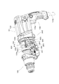
- FIG. 1 is a cross-sectional view for explaining the outline of the hammer drill 100.
- the hammer drill 100 is a hand-held work tool having a hand grip 109 held by a user.
- the hammer drill 100 drives the tool bit 119 linearly in the long axis direction of the tool bit 119 to perform a striking operation on the workpiece, and rotates the tool bit 119 around the long axis direction. It is configured to perform a rotating operation for performing a drilling operation on a workpiece.
- the user can set the driving mode of the tool bit 119 by a mode change lever (not shown).
- the hammer drill 100 according to the present embodiment has a hammer drill mode in which the tool bit 119 performs a striking operation and a rotation operation, and a drill mode in which the tool bit 119 performs only a rotation operation.
- the tool holder 159 is configured to make the tool bit 119 detachable.
- the tool holder 159 extends in a predetermined major axis direction, and the major axis direction of the tool holder 159 defines the main body major axis direction which is the major axis direction of the hammer drill 100.
- the major axis direction of the tool bit 119 when the tool bit 119 is mounted on the hammer drill 100 is parallel to the major axis direction of the main body.
- the hammer drill 100 is an example of the “work tool” according to the present invention
- the tool bit 119 is an example of the “tip tool” according to the present invention.
- the tip side of the tool holder 159 in the main body longitudinal direction is defined as the front side
- the handgrip 109 side facing the front side is defined as the rear side.
- the side on which the tool holder 159 is disposed is defined as the upper side
- the side on which the hand grip 109 is disposed is defined as the lower side. That is, the left side, right side, upper side, and lower side in FIG. 1 indicate the front side, rear side, upper side, and lower side of the hammer drill 100.
- position of the hammer drill 100 described in this figure is applied also to FIG.2, FIG.3, FIG.5, FIG.8, FIG.9 and FIG.
- a tool holder 159 is provided on the front side of the main body housing 101, and a hand grip 109 that is held by the user is provided on the rear side.
- a trigger 109 a for energizing the drive motor 110 is provided on the front side of the hand grip 109.
- a power cable 109 b for supplying current to the drive motor 110 is provided below the hand grip 109.
- the outline of the hammer drill 100 is constituted by a main body housing 101.
- the main body housing 101 is mainly composed of a motor housing 103, a gear housing 105, and an inner housing 130.
- the motor housing 103 and the gear housing 105 constitute the main part in the outer contour of the hammer drill 100.
- the main body housing 101 is an example of the “main body” according to the present invention.
- the drive motor 110 has an output shaft portion 111.
- the output shaft portion 111 is rotatably supported by a bearing 111 a fixed to the inner housing 130 and a bearing 111 b fixed to the motor housing 103.
- the output shaft 111 is provided with a fan 112 and a pinion gear 113 that can rotate integrally with the output shaft 111.
- the fan 112 blows air to the drive motor 110 by the rotation operation of the output shaft portion 111 to cool the drive motor 110.
- the drive motor 110 is an example embodiment that corresponds to the “drive motor” according to the present invention.
- FIG. 2 is an enlarged cross-sectional view for explaining the tip tool driving mechanism.
- the tip tool driving mechanism mainly includes a motion conversion mechanism 120 and a striking element 140 for driving the tool bit 119 in a straight line, and a rotation transmission mechanism 150 for rotating the tool bit 119. Is done.
- the mechanism constituted by the motion conversion mechanism 120 and the striking element 140 is an example of the “tip tool driving mechanism” according to the present invention.
- the rotation transmission mechanism 150 includes an intermediate shaft portion 116 that can rotate around a rotation shaft 116 c.
- the rotation shaft 116c is parallel to the output shaft 111 of the drive motor 110 and a drive shaft 140a defined by a tip tool drive mechanism described later.
- the intermediate shaft 116 is an example of the “rotary shaft member” according to the present invention
- the rotational shaft 116c is an example of the “rotating shaft” according to the present invention.
- the front side of the intermediate shaft portion 116 is attached to the gear housing 105 via a bearing 116a, and the rear side is attached to the gear housing 105 via a bearing 116b.
- a driven gear 117 that meshes with the pinion gear 113 of the drive motor 110 is provided on the rear side of the intermediate shaft portion 116, and a first gear 151 that meshes with the second gear 153 integrated with the sleeve 129 is provided on the front side.
- the sleeve 129 is integrated with the tool holder 159 by being connected to the tool holder 159 via a ring spring 159a. Further, the sleeve 129 is rotatably disposed in the main body housing 101 by being attached to the gear housing 105 on the front side via the bearing 129a and attached to the inner housing 130 via the bearing 129b. With this configuration, the output of the pinion gear 113 is transmitted to the driven gear 117, and the intermediate shaft portion 116 is rotated. Then, the rotation of the intermediate shaft portion 116 is transmitted to the sleeve 129 via the first gear 151 and the second gear 153, and the tool bit 119 is rotationally driven together with the tool holder 159.
- the motion conversion mechanism 120 is mainly configured by a clutch cam 180, a rotating body 123, and a swing shaft portion 125.
- the rotating body 123 is configured to be rotatable with respect to the intermediate shaft portion 116.
- Clutch cam 180 is splined to intermediate shaft portion 116, is movable in the direction of rotating shaft 116 c, and is rotated as intermediate shaft portion 116 rotates.
- the clutch cam 180 is moved in the front-rear direction in conjunction with the operation of the mode change lever by the user. Details of the mode change lever are omitted for convenience.
- the mode change lever selects the hammer drill mode
- the clutch cam 180 is moved to the rear side, and the clutch teeth 180a of the clutch cam 180 and the clutch teeth 123a of the rotating body 123 are engaged. Therefore, in this case, the tool holder 159 is rotated and the rotating body 123 is rotated, and the piston 127 is driven as described later.
- the mode change lever selects the drill mode
- the clutch cam 180 is moved forward, and the engagement of the clutch teeth 180a and the clutch teeth 123a is released. Therefore, in this case, while the tool holder 159 is rotationally driven, the rotation of the intermediate shaft portion 116 is not transmitted to the rotating body 123 and the piston 127 is not driven.
- 1 and 2 show a state in which the drill mode is selected.
- the rotating body 123 has an outer peripheral surface 123c having a predetermined inclination angle with respect to the rotating shaft 116a.
- the swing shaft portion 125 is attached to the outer peripheral surface 123c of the rotating body 123 via a plurality of steel balls 123b and is provided so as to protrude upward from the annular portion 125b and an annular portion 125b that surrounds the periphery of the rotating body 123.
- the shaft portion 125a connected to the piston 127 via the joint pin 126 and the shaft portion 125a in the annular portion 125b are provided to project downward from the opposite side (lower side) and are connected to a connecting member 250 described later. And a convex portion 125c.
- the shaft portion 125a and the joint pin 127 are connected so as to be relatively rotatable, and constitute a tip tool drive mechanism connection portion. Moreover, the convex part 125c and the connection member 250 are connected so that rotation is relatively possible, and comprise the connection member connection mechanism.
- the swing shaft portion 125 is an example of the “swing member” according to the present invention. With this configuration, the annular portion 125 b follows the transition of the inclination angle of the outer peripheral surface 123 c accompanying the rotation of the rotating body 123, so that the shaft portion 123 a is swung in the front-rear direction along the rotation shaft 123.
- the tip tool driving mechanism is driven by a linear motion component in the swinging motion of the shaft portion 123a as described later.
- the shaft portion 125a and the convex portion 125c are in a positional relationship facing each other with respect to the rotation shaft 116c. Therefore, when the shaft portion 125a is directed to the front side, the convex portion 125c is directed to the rear side. Further, when the shaft portion 125a is directed to the rear side, the convex portion 125c is directed to the front side.
- the striking element 140 includes a piston 127 formed of a bottomed tubular member slidably disposed on the inner cylinder of the sleeve 129, and a striking element slidably disposed on the inner cylinder of the piston 127. And an impact bolt 145 serving as an intermediate for transmitting the kinetic energy of the striker 143 to the tool bit 119.
- An air chamber 127a is formed between the bottom of the piston 127 and the striker 143.
- the striker 143 is linearly driven by pressure fluctuations in the air chamber 127a as the piston 127 reciprocates in the sleeve 129. Is done. That is, when the piston 127 moves forward and compresses the air in the air chamber 127a, the striker 143 is pushed forward and collides with the impact bolt 145 as the compressed air expands. Move to the front side. On the other hand, when the piston 127 moves to the rear side, the air in the air chamber 127a is expanded. The striker 143 is pulled back with the negative pressure of the expanded air. During the machining operation, the tip of the tool bit 119 is pressed by the user.
- the impact bolt 145 is moved to the rear side by being pushed by the rear end of the tool bit 119.
- the impact bolt 145 moved to the rear side is moved to the front side as the piston 127 moves to the front side as described above, and collides with the tool bit 119.
- the tool bit 119 is continuously driven linearly.
- the operation of the hitting element 140 described above defines the hitting shaft 140a shown in FIG.
- the striking shaft 140a is parallel to the rotation shaft 116c.
- the striking shaft 140a is an example of the “drive shaft” according to the present invention.
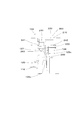
- FIG. 3 is an explanatory diagram showing a main part of the vibration damping mechanism 200.
- the vibration damping mechanism 200 includes a dynamic vibration absorber 210 and a connecting member 250.
- the vibration damping mechanism 200 is an example of the “vibration damping mechanism” according to the present invention
- the dynamic vibration absorber 210 is an example of the “dynamic vibration absorber” according to the present invention
- the connection member 250 is the “connection member” according to the present invention. Is an example.
- FIG. 4 is a cross-sectional view taken along line II in FIG.
- the dynamic vibration absorber 210 includes a plurality of shafts 220 arranged over the front portion 130 a of the inner housing 130 and the rear portion 130 b of the inner housing 130, a weight 230 inserted through the shaft 220, and the weight And an elastic member 240 for urging 230.
- five shafts 220 are used, but the number of shafts 220 can be selected according to the configuration of the dynamic vibration absorber 210 to be realized.
- the extending direction of the shaft 220 is parallel to the striking shaft 140a.
- the weight 230 has an insertion hole 230a, and the shaft 220 passes through the insertion hole 230a.
- the shaft 220 is an example of the “shaft” according to the present invention
- the weight 230 is an example of the “weight” according to the present invention
- the elastic member 240 is an example of the “elastic member” according to the present invention.
- the elastic member 240 is disposed on a part of the plurality of shafts 220.
- the elastic member 240 is disposed on the pair of shafts 220 at positions facing each other across the striking shaft 140a.
- FIG. 5 is an explanatory diagram of the shaft 220 on which the elastic member 240 is arranged.
- the elastic member 240 includes a first elastic member 241 disposed between the front portion 130a of the inner housing 130 and the front side of the weight 230, and a second elastic member 240 disposed between the rear portion 130b of the inner housing 130 and the rear side of the weight 230. And an elastic member 242. With this configuration, the weight 230 can reciprocate with respect to the shaft 220.
- FIG. 6 is a cross-sectional view taken along line II-II in FIG.
- the weight 230 surrounds the hitting shaft 140a around the hitting shaft 140a.
- the weight 230 can easily reciprocate due to vibration in the direction along the striking shaft 140a when the striking element 140 is driven. That is, the dynamic vibration absorber 210 can effectively suppress vibration in the direction of the striking shaft 140a.
- the weight 230 has a pair of end part area
- the connecting member 250 surrounds the rotation shaft 116c around the rotation shaft 116c. With this configuration, the connecting member 250 can be efficiently arranged around the intermediate shaft portion 116. Moreover, the connection member 250 has a pair of edge part area
- the end region 251 is an example of the “end region” according to the present invention, and the intermediate region 252 is an example of the “intermediate region” according to the present invention.
- the end region 251 of the connecting member 250 is connected to the end region 231 of the weight 230 so as to be rotatable about the fulcrum shaft 260a.
- the intermediate region 252 of the connecting member 250 has an intermediate hole portion 252a, and the convex portion 125c of the swing shaft portion 125 is inserted into the intermediate hole portion 252a. With this configuration, the connecting member 250 is moved in the front-rear direction as the swinging shaft portion 125 rotates.
- FIG. 7 is an explanatory diagram showing a connection structure between the weight 230 and the connecting member 250.
- a cylindrical fulcrum shaft portion 260 is formed in the end hole portion 231 a formed in the end region 231 of the weight 230 and the end hole portion 251 a formed in the end region 251 of the connecting member 250. Is installed.
- a recessed portion is formed in the outer region of the connecting member 250 in the fulcrum shaft portion 260, and a retaining ring 261 for preventing the connecting member 250 from coming off is attached to the recessed portion.
- the weight 230 and the connecting member 250 are configured to be relatively rotatable about the fulcrum shaft 260a.
- This fulcrum shaft 260a is an example of the “fulcrum shaft” according to the present invention.
- FIG. 8 shows a state in which the extending direction of the shaft portion 125a of the swing shaft portion 125 is placed in a direction orthogonal to the rotation shaft 116c.
- a center line 250a connecting the center point between the pair of fulcrum shaft portions 260 and the center point of the intermediate hole portion 252a of the connecting member 250 passes through the center line 250a and is orthogonal to the rotation shaft 116c.
- a predetermined inclination angle with respect to the rotating axis orthogonal line 116d is also known inclination angle with respect to the rotating axis orthogonal line 116d.
- the fulcrum shaft portion 260 is disposed behind the intermediate hole portion 252a. Since the fulcrum shaft portion 260 and the intermediate hole portion 252 are arranged in this manner, the connecting member 250 has a communication region 253 that extends between the end region 251 and the intermediate region 252. Since the connecting member 250 has the configuration, the connecting member 250 can be efficiently arranged in a limited space, and as a result, the hammer drill 100 can be downsized.
- the weight 230 is reciprocated together with the connecting member 250 by the vibration accompanying the driving of the rotation transmission mechanism 150 and the vibration accompanying the operation of the hammer drill 100 by the user, thereby suppressing the vibration.
- the weight 230 reciprocates linearly by sliding on the shaft 220.
- the connecting member 250 rotates around the intermediate hole 252a by the reciprocating movement of the fulcrum shaft 260 along with the linear reciprocating movement of the weight 230.
- FIG. 9 shows a state in which the shaft portion 125a is inclined forward as the intermediate shaft portion 116 rotates.
- the vibration damping mechanism 200 in this state is set to the second state.
- the tool bit 119 is moved to the front side by the shaft portion 125a moving the piston 127 to the front side.
- the weight 230 is moved rearward via the connecting member 250.
- the first elastic member 241 urges the weight 230 to assist the backward movement of the weight 230.
- the second elastic member 242 is compressed by the weight 230.
- the swing shaft 125 swings from the second state to the state where the shaft 125a shown in FIG. 10 is inclined rearward through the first state.
- the vibration damping mechanism 200 in this state is set to the third state.
- the shaft portion 125a is inclined to the rear side, and the convex portion 125c is inclined to the front side. Therefore, the shaft part 125a moves the piston 127 to the rear side, and accordingly, the air in the air chamber 127a is expanded and the striker 143 is moved to the rear side. Since the user presses the tool bit 119 against the workpiece, the tool bit 119 is moved rearward together with the impact bolt 145.
- the weight 230 is moved to the front side via the connecting member 250.
- the second elastic member 242 urges the weight 230 to assist the forward movement of the weight 230.
- the first elastic member 241 is compressed by the weight 230.
- the vibration damping mechanism 200 has the weight 230 based on the swinging motion of the swinging shaft portion 125 between the second state and the third state via the first state. Is configured to reciprocate directly and forcibly. Therefore, it can be said that the vibration control mechanism 200 has a weight forced reciprocation mechanism.
- the vibration control mechanism 200 is an assist for shifting the weight 230 from a stationary state to a moving state. It can be called a mechanism.
- the vibration control mechanism 200 is an assist for shifting the weight 230 from a stationary state to a moving state. It can be called a mechanism.
- the dynamic vibration absorber 210 including only the weight 230 and the elastic member 240
- the weight 230 is reciprocated only by vibration generated in the main body housing 101. Therefore, the distance that the weight 230 reciprocates depends on the magnitude of vibration with respect to the main body housing 101.
- the vibration damping mechanism 200 according to the present invention the weight 230 is forcibly reciprocated between the second state and the third state described above via the connecting member 250.
- the vibration damping mechanism 200 constitutes a mechanism for increasing the amount of reciprocating movement of the weight 230 in a situation where the amount of reciprocating movement of the weight 230 in the dynamic vibration absorber 210 including only the weight 230 and the elastic member 240 is small. It can be said.
- the vibration control mechanism 200 constitutes a mechanism for adjusting the amount of reciprocation of the weight 230 in a situation where the amount of reciprocation of the weight 230 in the dynamic vibration absorber 210 including only the weight 230 and the elastic member 240 is large. It can be said.
- the connecting member 250 in the vibration damping mechanism 200 is configured to be rotatable with respect to both the weight 230 and the swinging shaft portion 125, the swinging member 125 is swung with the swinging motion.
- the weight 230 can be reciprocated linearly.
- the connecting member 250 is rotatable with respect to both the weight 230 and the swing shaft portion 125, it can be said that the vibration control mechanism 200 constitutes a phase changing mechanism in the reciprocating movement of the weight 230.
- the connecting member 250 constitutes a counterweight because it is reciprocated with the swinging motion of the swinging shaft portion 250. That is, the vibration damping mechanism 200 according to the present invention can configure the vibration damping mechanism 200 suitable for the work tool 100 to be realized by combining various functions.
- composition of a work tool concerning the present invention.
- an electric reciprocating saw that performs a cutting operation on a workpiece such as wood by driving a tip tool linearly as a work tool.
- the hand grip 109 is formed in a cantilever shape extending downward, the hand grip 109 may be formed in a loop shape.
- the output shaft portion 111 of the electric motor 110 is disposed in parallel with the rotation shaft 116c, the output shaft portion 111 of the electric motor 110 may be disposed so as to intersect the rotation shaft 116c. In this case, the output shaft portion 111 and the intermediate shaft portion 116 are preferably engaged via a bevel gear.
- the rotating shaft member includes a rotating body having an outer peripheral surface having a predetermined inclination angle with respect to the rotating shaft,
- the swinging shaft portion is provided so as to be rotatable relative to the outer peripheral surface, and protrudes from the annular portion and is rotatable relative to the tip tool drive mechanism. It has a connected shaft portion, and a convex portion provided so as to protrude from a side facing the shaft portion in the annular portion and rotatably connected to the connecting member.
- the vibration control mechanism includes a first connecting portion that connects the swing member and the tip tool drive mechanism in a relatively rotatable manner, and the swing member and the connecting member in a relatively rotatable manner. It has the 2nd connection part to connect, It is characterized by the above-mentioned. (Aspect 3) The first connection part and the second connection part can be placed at positions facing each other across the rotation shaft.
- the correspondence between each component of the present embodiment and each component of the present invention is as follows.
- this embodiment shows an example of the form for implementing this invention, and this invention is not limited to the structure of this embodiment.
- the hammer drill 100 is an example embodiment that corresponds to the “work tool” according to the present invention.
- the tool bit 119 is an example of the “tip tool” according to the present invention.
- the main body housing 101 is an example embodiment that corresponds to the “main body” according to the present invention.
- the drive motor 110 is an example embodiment that corresponds to the “drive motor” according to the present invention.
- the intermediate shaft portion 116 is an example of the “rotary shaft member” according to the present invention.
- the rotating shaft 116c is an example embodiment that corresponds to the “rotating shaft” according to the present invention.
- the swing shaft portion 125 is an example of the “swing member” according to the present invention.
- the striking shaft 140a is an example embodiment that corresponds to the “drive shaft” according to the present invention.
- the damping mechanism 200 is an example of the “damping mechanism” according to the present invention.
- the dynamic vibration absorber 210 is an example of the “dynamic vibration absorber” according to the present invention.
- the connecting member 250 is an example of the “connecting member” according to the present invention.
- the shaft 220 is an example of the “shaft” according to the present invention.
- the weight 230 is an example of the “weight” according to the present invention.
- the elastic member 240 is an example of the “elastic member” according to the present invention.
- the end region 251 is an example of the “end region” according to the present invention, and the intermediate region 252 is an example of the “intermediate region” according to the present invention.
- the fulcrum shaft 260a is an example of the “fulcrum shaft” according to the present invention.
Abstract
L'invention a pour but de fournir une technique raisonnable pour un outil de travail pourvu d'un mécanisme pour réduire à un minimum les vibrations. Pour atteindre ce but, selon l'invention, un mécanisme de suppression des vibrations (200) disposé sur un outil de travail (100) possède un amortisseur de vibrations dynamique (210), actionné par un élément élastique (240) et pourvu d'un poids (230) capable d'un mouvement alternatif, et un élément de liaison (250) reliant le poids (230) et un élément oscillant (125) qui entraîne un mécanisme d'entraînement d'outil d'extrémité distale. Le poids (230) subit un mouvement alternatif par l'intermédiaire de l'élément de liaison (250) sur la base d'un mouvement d'oscillation de l'élément oscillant (125).
Priority Applications (3)
| Application Number | Priority Date | Filing Date | Title |
|---|---|---|---|
| EP16743440.6A EP3235599A4 (fr) | 2015-01-29 | 2016-01-27 | Outil de travail |
| CN201680007504.3A CN107206584B (zh) | 2015-01-29 | 2016-01-27 | 作业工具 |
| US15/545,972 US10518400B2 (en) | 2015-01-29 | 2016-01-27 | Work tool |
Applications Claiming Priority (2)
| Application Number | Priority Date | Filing Date | Title |
|---|---|---|---|
| JP2015-015503 | 2015-01-29 | ||
| JP2015015503A JP6510250B2 (ja) | 2015-01-29 | 2015-01-29 | 作業工具 |
Publications (1)
| Publication Number | Publication Date |
|---|---|
| WO2016121837A1 true WO2016121837A1 (fr) | 2016-08-04 |
Family
ID=56543445
Family Applications (1)
| Application Number | Title | Priority Date | Filing Date |
|---|---|---|---|
| PCT/JP2016/052392 WO2016121837A1 (fr) | 2015-01-29 | 2016-01-27 | Outil de travail |
Country Status (5)
| Country | Link |
|---|---|
| US (1) | US10518400B2 (fr) |
| EP (1) | EP3235599A4 (fr) |
| JP (1) | JP6510250B2 (fr) |
| CN (1) | CN107206584B (fr) |
| WO (1) | WO2016121837A1 (fr) |
Families Citing this family (5)
| Publication number | Priority date | Publication date | Assignee | Title |
|---|---|---|---|---|
| JP6987599B2 (ja) * | 2017-10-20 | 2022-01-05 | 株式会社マキタ | 打撃工具 |
| JP7251612B2 (ja) * | 2019-03-28 | 2023-04-04 | 工機ホールディングス株式会社 | 打撃作業機 |
| US11826891B2 (en) | 2019-10-21 | 2023-11-28 | Makita Corporation | Power tool having hammer mechanism |
| US11845168B2 (en) * | 2019-11-01 | 2023-12-19 | Makita Corporation | Reciprocating tool |
| US11642769B2 (en) * | 2021-02-22 | 2023-05-09 | Makita Corporation | Power tool having a hammer mechanism |
Citations (7)
| Publication number | Priority date | Publication date | Assignee | Title |
|---|---|---|---|---|
| GB2129733A (en) * | 1982-10-27 | 1984-05-23 | Jean Walton | More-vibration-free concrete breakers and percussion drills |
| JPH09277167A (ja) * | 1995-11-27 | 1997-10-28 | Sb Power Tool Co | 往復駆動機構 |
| JP2008073836A (ja) * | 2006-08-24 | 2008-04-03 | Makita Corp | 打撃工具 |
| US20100270046A1 (en) * | 2007-12-19 | 2010-10-28 | Gerd Schlesak | Swash drive of a hand-held power tool |
| JP2010260145A (ja) * | 2009-05-08 | 2010-11-18 | Makita Corp | 打撃工具 |
| JP2013049125A (ja) * | 2011-08-31 | 2013-03-14 | Makita Corp | 打撃工具 |
| US20150000945A1 (en) * | 2013-06-28 | 2015-01-01 | Robert Bosch Gmbh | Hand-Held Power Tool Drive Device |
Family Cites Families (17)
| Publication number | Priority date | Publication date | Assignee | Title |
|---|---|---|---|---|
| SU1617139A1 (ru) * | 1988-08-09 | 1990-12-30 | Московское Научно-Производственное Объединение По Механизированному Строительному Инструменту И Отделочным Машинам | Компрессионно-вакуумна машина ударного действи |
| DE19851888C1 (de) * | 1998-11-11 | 2000-07-13 | Metabowerke Kg | Bohrhammer |
| JP4195818B2 (ja) * | 2003-01-16 | 2008-12-17 | 株式会社マキタ | 電動ハンマ |
| DK1818141T3 (da) | 2003-03-21 | 2010-08-23 | Black & Decker Inc | Vibrationsreduceringsindretning til værktøjsmaskine og værktøjsmaskine, der indeholder en sådan indretning |
| EP1464449B1 (fr) * | 2003-04-01 | 2010-03-24 | Makita Corporation | Outil électrique |
| JP4155857B2 (ja) * | 2003-04-01 | 2008-09-24 | 株式会社マキタ | 作業工具 |
| EP1475190B1 (fr) * | 2003-05-09 | 2010-03-31 | Makita Corporation | Outil électrique |
| US7604071B2 (en) * | 2004-04-30 | 2009-10-20 | Makita Corporation | Power tool with vibration reducing means |
| JP2007175839A (ja) * | 2005-12-28 | 2007-07-12 | Hitachi Koki Co Ltd | 打撃工具 |
| JP5135722B2 (ja) * | 2006-06-19 | 2013-02-06 | 株式会社ジェイテクト | 車両用操舵装置 |
| US7832498B2 (en) * | 2007-06-15 | 2010-11-16 | Makita Corporation | Impact tool |
| JP5009059B2 (ja) * | 2007-06-15 | 2012-08-22 | 株式会社マキタ | 打撃工具 |
| US7806201B2 (en) * | 2007-07-24 | 2010-10-05 | Makita Corporation | Power tool with dynamic vibration damping |
| JP2010250145A (ja) | 2009-04-17 | 2010-11-04 | Seiko Epson Corp | 表示装置の検査装置及び検査方法 |
| US9618257B2 (en) * | 2010-06-09 | 2017-04-11 | Quantum Design International, Inc. | Gas-flow cryostat for dynamic temperature regulation using a fluid level sensor |
| DE102011077220A1 (de) * | 2010-12-21 | 2012-06-21 | Robert Bosch Gmbh | Elektrohandwerkzeug |
| US9156152B2 (en) * | 2011-08-31 | 2015-10-13 | Makita Corporation | Impact tool having counter weight that reduces vibration |
-
2015
- 2015-01-29 JP JP2015015503A patent/JP6510250B2/ja active Active
-
2016
- 2016-01-27 EP EP16743440.6A patent/EP3235599A4/fr active Pending
- 2016-01-27 WO PCT/JP2016/052392 patent/WO2016121837A1/fr active Application Filing
- 2016-01-27 CN CN201680007504.3A patent/CN107206584B/zh active Active
- 2016-01-27 US US15/545,972 patent/US10518400B2/en active Active
Patent Citations (7)
| Publication number | Priority date | Publication date | Assignee | Title |
|---|---|---|---|---|
| GB2129733A (en) * | 1982-10-27 | 1984-05-23 | Jean Walton | More-vibration-free concrete breakers and percussion drills |
| JPH09277167A (ja) * | 1995-11-27 | 1997-10-28 | Sb Power Tool Co | 往復駆動機構 |
| JP2008073836A (ja) * | 2006-08-24 | 2008-04-03 | Makita Corp | 打撃工具 |
| US20100270046A1 (en) * | 2007-12-19 | 2010-10-28 | Gerd Schlesak | Swash drive of a hand-held power tool |
| JP2010260145A (ja) * | 2009-05-08 | 2010-11-18 | Makita Corp | 打撃工具 |
| JP2013049125A (ja) * | 2011-08-31 | 2013-03-14 | Makita Corp | 打撃工具 |
| US20150000945A1 (en) * | 2013-06-28 | 2015-01-01 | Robert Bosch Gmbh | Hand-Held Power Tool Drive Device |
Non-Patent Citations (1)
| Title |
|---|
| See also references of EP3235599A4 * |
Also Published As
| Publication number | Publication date |
|---|---|
| JP2016137559A (ja) | 2016-08-04 |
| CN107206584A (zh) | 2017-09-26 |
| CN107206584B (zh) | 2021-06-29 |
| US20180001463A1 (en) | 2018-01-04 |
| JP6510250B2 (ja) | 2019-05-08 |
| US10518400B2 (en) | 2019-12-31 |
| EP3235599A1 (fr) | 2017-10-25 |
| EP3235599A4 (fr) | 2018-08-29 |
Similar Documents
| Publication | Publication Date | Title |
|---|---|---|
| JP6096593B2 (ja) | 往復動式作業工具 | |
| WO2016121837A1 (fr) | Outil de travail | |
| JP5345893B2 (ja) | 打撃工具 | |
| JP6334144B2 (ja) | 往復動式作業工具 | |
| JP6479570B2 (ja) | 作業工具 | |
| JP6367617B2 (ja) | 往復動式作業工具 | |
| JP5294726B2 (ja) | 手持式作業工具 | |
| JP4270887B2 (ja) | 電動往復動式工具 | |
| JP6441588B2 (ja) | 打撃工具 | |
| JP5767511B2 (ja) | 往復動式作業工具 | |
| JP2006272511A (ja) | 往復作動式作業工具 | |
| JP2009248241A (ja) | 手持式作業工具 | |
| JP2006159308A (ja) | 往復動式作業工具 | |
| CN107107322B (zh) | 冲击工具 | |
| WO2006041139A1 (fr) | Outil de travail a mouvement de va-et-vient | |
| JP2017042887A (ja) | 打撃工具 | |
| JP6517634B2 (ja) | 打撃工具 | |
| JP2007203388A (ja) | 打撃工具 | |
| JP6348337B2 (ja) | 往復動式作業工具 | |
| JP5058726B2 (ja) | 打撃工具 | |
| JP6517633B2 (ja) | 打撃工具 | |
| WO2014142112A1 (fr) | Outil à percussion | |
| JP6612496B2 (ja) | 打撃工具 | |
| JP6335049B2 (ja) | 打撃工具 |
Legal Events
| Date | Code | Title | Description |
|---|---|---|---|
| 121 | Ep: the epo has been informed by wipo that ep was designated in this application |
Ref document number: 16743440 Country of ref document: EP Kind code of ref document: A1 |
|
| REEP | Request for entry into the european phase |
Ref document number: 2016743440 Country of ref document: EP |
|
| WWE | Wipo information: entry into national phase |
Ref document number: 15545972 Country of ref document: US |
|
| NENP | Non-entry into the national phase |
Ref country code: DE |