WO2016121837A1 - Work tool - Google Patents
Work tool Download PDFInfo
- Publication number
- WO2016121837A1 WO2016121837A1 PCT/JP2016/052392 JP2016052392W WO2016121837A1 WO 2016121837 A1 WO2016121837 A1 WO 2016121837A1 JP 2016052392 W JP2016052392 W JP 2016052392W WO 2016121837 A1 WO2016121837 A1 WO 2016121837A1
- Authority
- WO
- WIPO (PCT)
- Prior art keywords
- weight
- shaft
- work tool
- connecting member
- swinging
- Prior art date
Links
Images


Classifications
-
- B—PERFORMING OPERATIONS; TRANSPORTING
- B25—HAND TOOLS; PORTABLE POWER-DRIVEN TOOLS; MANIPULATORS
- B25D—PERCUSSIVE TOOLS
- B25D17/00—Details of, or accessories for, portable power-driven percussive tools
- B25D17/24—Damping the reaction force
-
- B—PERFORMING OPERATIONS; TRANSPORTING
- B25—HAND TOOLS; PORTABLE POWER-DRIVEN TOOLS; MANIPULATORS
- B25D—PERCUSSIVE TOOLS
- B25D11/00—Portable percussive tools with electromotor or other motor drive
- B25D11/06—Means for driving the impulse member
- B25D11/062—Means for driving the impulse member comprising a wobbling mechanism, swash plate
-
- B—PERFORMING OPERATIONS; TRANSPORTING
- B25—HAND TOOLS; PORTABLE POWER-DRIVEN TOOLS; MANIPULATORS
- B25D—PERCUSSIVE TOOLS
- B25D11/00—Portable percussive tools with electromotor or other motor drive
- B25D11/06—Means for driving the impulse member
- B25D11/10—Means for driving the impulse member comprising a cam mechanism
-
- B—PERFORMING OPERATIONS; TRANSPORTING
- B25—HAND TOOLS; PORTABLE POWER-DRIVEN TOOLS; MANIPULATORS
- B25D—PERCUSSIVE TOOLS
- B25D11/00—Portable percussive tools with electromotor or other motor drive
- B25D11/06—Means for driving the impulse member
- B25D11/12—Means for driving the impulse member comprising a crank mechanism
- B25D11/125—Means for driving the impulse member comprising a crank mechanism with a fluid cushion between the crank drive and the striking body
-
- B—PERFORMING OPERATIONS; TRANSPORTING
- B25—HAND TOOLS; PORTABLE POWER-DRIVEN TOOLS; MANIPULATORS
- B25F—COMBINATION OR MULTI-PURPOSE TOOLS NOT OTHERWISE PROVIDED FOR; DETAILS OR COMPONENTS OF PORTABLE POWER-DRIVEN TOOLS NOT PARTICULARLY RELATED TO THE OPERATIONS PERFORMED AND NOT OTHERWISE PROVIDED FOR
- B25F5/00—Details or components of portable power-driven tools not particularly related to the operations performed and not otherwise provided for
- B25F5/006—Vibration damping means
-
- B—PERFORMING OPERATIONS; TRANSPORTING
- B25—HAND TOOLS; PORTABLE POWER-DRIVEN TOOLS; MANIPULATORS
- B25D—PERCUSSIVE TOOLS
- B25D11/00—Portable percussive tools with electromotor or other motor drive
- B25D11/06—Means for driving the impulse member
- B25D11/066—Means for driving the impulse member using centrifugal or rotary impact elements
-
- B—PERFORMING OPERATIONS; TRANSPORTING
- B25—HAND TOOLS; PORTABLE POWER-DRIVEN TOOLS; MANIPULATORS
- B25D—PERCUSSIVE TOOLS
- B25D2211/00—Details of portable percussive tools with electromotor or other motor drive
- B25D2211/06—Means for driving the impulse member
- B25D2211/061—Swash-plate actuated impulse-driving mechanisms
-
- B—PERFORMING OPERATIONS; TRANSPORTING
- B25—HAND TOOLS; PORTABLE POWER-DRIVEN TOOLS; MANIPULATORS
- B25D—PERCUSSIVE TOOLS
- B25D2211/00—Details of portable percussive tools with electromotor or other motor drive
- B25D2211/06—Means for driving the impulse member
- B25D2211/068—Crank-actuated impulse-driving mechanisms
-
- B—PERFORMING OPERATIONS; TRANSPORTING
- B25—HAND TOOLS; PORTABLE POWER-DRIVEN TOOLS; MANIPULATORS
- B25D—PERCUSSIVE TOOLS
- B25D2217/00—Details of, or accessories for, portable power-driven percussive tools
- B25D2217/0073—Arrangements for damping of the reaction force
- B25D2217/0076—Arrangements for damping of the reaction force by use of counterweights
- B25D2217/0088—Arrangements for damping of the reaction force by use of counterweights being mechanically-driven
-
- B—PERFORMING OPERATIONS; TRANSPORTING
- B25—HAND TOOLS; PORTABLE POWER-DRIVEN TOOLS; MANIPULATORS
- B25D—PERCUSSIVE TOOLS
- B25D2217/00—Details of, or accessories for, portable power-driven percussive tools
- B25D2217/0073—Arrangements for damping of the reaction force
- B25D2217/0076—Arrangements for damping of the reaction force by use of counterweights
- B25D2217/0092—Arrangements for damping of the reaction force by use of counterweights being spring-mounted
-
- B—PERFORMING OPERATIONS; TRANSPORTING
- B25—HAND TOOLS; PORTABLE POWER-DRIVEN TOOLS; MANIPULATORS
- B25D—PERCUSSIVE TOOLS
- B25D2250/00—General details of portable percussive tools; Components used in portable percussive tools
- B25D2250/331—Use of bearings
- B25D2250/335—Supports therefor
Landscapes
- Engineering & Computer Science (AREA)
- Mechanical Engineering (AREA)
- Percussive Tools And Related Accessories (AREA)
Abstract
[Problem] To provide a reasonable technique for a work tool equipped with a mechanism for minimizing vibration. [Solution] A vibration-suppressing mechanism (200) provided to a work tool (100) has a dynamic vibration absorber (210) energized by an elastic member (240) and furnished with a weight (230) capable of reciprocating motion, and a linking member (250) linking the weight (230) and an oscillating member (125) which drives a distal end tool driving mechanism. the weight (230) undergoes reciprocating motion via the linking member (250) on the basis of oscillation motion of the oscillating member (125).
Description
本発明は、先端工具を直線状に駆動することにより被加工材に所定の加工作業を行う作業工具に関する。
The present invention relates to a work tool that performs a predetermined machining operation on a workpiece by driving a tip tool linearly.
特開2010-250145号公報には、シャフト上に配置されたウェイトと、当該ウェイトの両側に配置された弾性部材とを有する動吸振器が設けられた作業工具が開示されている。
Japanese Patent Application Laid-Open No. 2010-250145 discloses a work tool provided with a dynamic vibration absorber having weights arranged on a shaft and elastic members arranged on both sides of the weight.
当該作業工具においては、一方の弾性部材の端部を往復移動させることによりウェイトを強制的に駆動していた。
In the work tool, the weight is forcibly driven by reciprocating the end of one elastic member.
当該作業工具においては、作業工具に発生する振動抑制に一定の効果があった。一方、振動を抑制するための機構として更なる構成が要請されていた。
This work tool had a certain effect on suppressing vibration generated in the work tool. On the other hand, a further configuration has been required as a mechanism for suppressing vibration.
本発明は上記の課題に鑑みてなされたものであり、振動を抑制する機構を備えた作業工具に係る一層合理的な技術を提供することを目的とする。
The present invention has been made in view of the above problems, and an object thereof is to provide a more rational technique related to a work tool having a mechanism for suppressing vibration.
上記課題を解決するため、本発明に係る作業工具は、先端工具を直線状に駆動することにより被加工材に所定の加工作業を行う作業工具であって、駆動モータと、駆動モータにより回転駆動される回転軸部材と、回転軸部材の回転動作に基づき揺動される揺動部材と、揺動部材の揺動動作に基づき先端工具を駆動させる先端工具駆動機構と、駆動モータと回転軸部材と揺動部材と先端工具駆動機構とを収容する本体部と、本体部に発生する振動を抑制する制振機構と、を有する。
先端工具を直線状に駆動する作業工具の具体例として、コンクリートなどの被加工材に対し粉砕作業を行う電動ハンマや、木材などの被加工材に対し切断作業を行う電動レシプロソーなどが挙げられる。この意味において、駆動モータや、回転軸部材や、揺動部材や、先端工具駆動機構は実現すべき作業工具に応じて種々の構成を採用することが可能である。 In order to solve the above problems, a work tool according to the present invention is a work tool that performs a predetermined machining operation on a workpiece by driving a tip tool linearly, and is driven to rotate by a drive motor and a drive motor. Rotating shaft member, swinging member swung based on the rotating operation of the rotating shaft member, tip tool driving mechanism for driving the tip tool based on the swinging operation of the swinging member, drive motor, and rotating shaft member And a swinging member and a tip tool drive mechanism, and a vibration damping mechanism that suppresses vibrations generated in the body portion.
Specific examples of the working tool for driving the tip tool linearly include an electric hammer that performs a crushing operation on a workpiece such as concrete, and an electric reciprocating saw that performs a cutting operation on a workpiece such as wood. In this sense, the driving motor, the rotating shaft member, the swinging member, and the tip tool driving mechanism can employ various configurations depending on the work tool to be realized.
例えば作業工具を電動ハンマとする場合、先端工具駆動機構は、揺動部材の揺動動作に基づき往復移動されるピストンと、当該ピストンの往復動作に基づき移動されることにより先端工具に衝突して当該先端工具を駆動する打撃子とにより構成することが可能となる。この場合、揺動部材と先端工具駆動機構は所定の接続位置により相対的に回動可能に構成される。
回転軸部材は、回転軸部材の回転軸に対して所定の傾斜角度を有する外周面を備えた回転体を有することができる。この場合、揺動部材は、回転体に対し回動可能に設けられた揺動軸部により構成することができる。揺動軸部は、回転体の周囲を包囲する環状部と、当該環状部に設けられる先端工具駆動機構接続部とを有することができる。先端工具駆動機構接続部は、環状部から延設された軸部により構成することができる。当該構成によって、回転体の回転に伴う外周面の傾斜角度の移行に環状部が追随することにより、軸部が回転軸に沿った方向にて揺動される。この軸部の揺動動作における直線運動成分によって、先端工具駆動機構が駆動される。 For example, when the working tool is an electric hammer, the tip tool drive mechanism collides with the tip tool by a piston that is reciprocated based on the swinging motion of the swinging member and a piston that is moved based on the reciprocating motion of the piston. It becomes possible to comprise with the striker which drives the said tip tool. In this case, the swing member and the tip tool driving mechanism are configured to be relatively rotatable by a predetermined connection position.
The rotating shaft member can include a rotating body having an outer peripheral surface having a predetermined inclination angle with respect to the rotating shaft of the rotating shaft member. In this case, the swing member can be configured by a swing shaft provided so as to be rotatable with respect to the rotating body. The oscillating shaft portion can include an annular portion that surrounds the periphery of the rotating body, and a tip tool drive mechanism connecting portion provided in the annular portion. The tip tool drive mechanism connecting portion can be constituted by a shaft portion extending from the annular portion. With this configuration, the annular portion follows the transition of the inclination angle of the outer peripheral surface accompanying the rotation of the rotating body, whereby the shaft portion is swung in the direction along the rotation axis. The tip tool drive mechanism is driven by the linear motion component in the swinging motion of the shaft portion.
本発明に係る作業工具において、制振機構は、弾性部材と、弾性部材により付勢されるとともに往復移動可能なウェイトとが設けられた動吸振器と、ウェイトと揺動部材とを連結する連結部材と、を有し、揺動部材の揺動動作に基づき連結部材を介してウェイトを往復移動する。
制振機構において、動吸振器は本体部に発生する振動に基づきウェイトが往復移動することにより当該振動を抑制する。当該動作を行うウェイトは、さらに、揺動部材の揺動動作に基づく連結部材の動作によって直接的かつ強制的に往復移動される。これによって、本発明に係る作業工具は、効果的に振動を抑制することが可能となる。なお上述した構成により、本発明に係る制振機構は、揺動部材の揺動動作に基づくウェイト強制往復移動機構を有するということができる。 In the work tool according to the present invention, the vibration damping mechanism includes a dynamic vibration absorber provided with an elastic member, a weight that is urged by the elastic member and is capable of reciprocating, and a connection that connects the weight and the rocking member. And the weight is reciprocated through the connecting member based on the swinging motion of the swinging member.
In the vibration damping mechanism, the dynamic vibration absorber suppresses the vibration by the weight reciprocating based on the vibration generated in the main body. The weight performing the operation is further reciprocated directly and forcibly by the operation of the connecting member based on the swinging motion of the swinging member. Thereby, the work tool according to the present invention can effectively suppress vibration. With the above-described configuration, it can be said that the vibration damping mechanism according to the present invention has a weight forced reciprocating mechanism based on the swinging motion of the swinging member.
なお、連結部材は、揺動部材に対して相対的に回動可能に接続される。この場合、揺動部材と連結部材の接続位置が設けられる揺動部材の領域は、揺動部材と先端工具駆動機構の接続位置が設けられる揺動部材の領域と対向することが好ましい。すなわち上述した構成を有する揺動部材の場合、揺動部材と連結部材の接続位置は、軸部と対向する環状部の領域に設けることができる。当該領域は揺動部材における連結部材接続部とすることができる。当該構成の場合、例えば揺動部材が揺動して先端工具駆動機構接続部が回転軸の一方側に向けられた状態にあっては、連結部材接続部は当該一方側と対向する他方側へ向けられる。また、揺動部材がさらに揺動し先端工具駆動機構接続部が他方側へ向けられた状態にあっては、連結部材接続部は一方側へ向けられる。すなわち、揺動部材の揺動に伴い、先端工具駆動機構接続部と連結部材接続部は逆位相にて移動される。つまり、揺動部材の揺動に伴い、先端工具駆動機構とウェイトが逆位相にて駆動されるため、より効果的に振動を抑制することが可能となる。
The connecting member is connected so as to be rotatable relative to the swinging member. In this case, it is preferable that the region of the swinging member where the connection position of the swinging member and the connecting member is provided is opposed to the region of the swinging member where the connection position of the swinging member and the tip tool drive mechanism is provided. That is, in the case of the swing member having the above-described configuration, the connection position of the swing member and the connecting member can be provided in the region of the annular portion facing the shaft portion. The region can be a connecting member connecting portion in the swing member. In the case of this configuration, for example, when the swinging member swings and the tip tool drive mechanism connecting portion is directed to one side of the rotating shaft, the connecting member connecting portion is directed to the other side facing the one side. Directed. Further, when the swinging member is further swung and the tip tool drive mechanism connecting portion is directed to the other side, the connecting member connecting portion is directed to one side. That is, as the swing member swings, the tip tool drive mechanism connecting portion and the connecting member connecting portion are moved in opposite phases. In other words, the tip tool driving mechanism and the weight are driven in opposite phases with the swing of the swing member, so that the vibration can be more effectively suppressed.
また本発明に係る作業工具の他の形態として、ウェイトと連結部材を、支点軸により相対的に回動可能に接続することができる。
本発明に係る作業工具において、ウェイトは直線状に往復移動されることが好ましい。一方、上述の構成を有する揺動部材における揺動動作は、回転軸に沿った回動動作となる。よって、連結部材においては揺動部材の回動動作をウェイトの直線動作へと変更する運動変換機能が要求される。この態様に係る作業工具においては、ウェイトと連結部材が相対的に回動可能とされているため、連結部材は揺動部材の回動動作に基づいて、円滑にウェイトを直線状に往復移動させることが可能となる。 As another form of the work tool according to the present invention, the weight and the connecting member can be connected to each other so as to be relatively rotatable by a fulcrum shaft.
In the work tool according to the present invention, the weight is preferably reciprocated linearly. On the other hand, the swinging operation in the swinging member having the above-described configuration is a rotating operation along the rotation axis. Therefore, the connecting member is required to have a motion conversion function for changing the swinging motion of the swing member to the linear motion of the weight. In the work tool according to this aspect, since the weight and the connecting member are relatively rotatable, the connecting member smoothly reciprocates the weight linearly based on the rotating operation of the swinging member. It becomes possible.
また本発明に係る作業工具の他の形態として、先端工具駆動機構は駆動軸を規定し、ウェイトは、駆動軸周りにおいて駆動軸を包囲するよう構成することができる。この場合、「駆動軸周り」とは駆動軸を中心とする真円もしくは真円上の円弧を指すものではなく、「駆動軸の周辺」を意味するものである。また、ウェイトが「駆動軸を包囲」とは駆動軸の周辺における全周を囲むことを意味するものではない。例えば、駆動軸と直交する所定方向と、当該所定方向とは異なる方向であるとともに駆動軸と交差する他の方向に亘りウェイトが設けられていれば足りるものである。
先端工具駆動機構が駆動された場合、駆動軸に沿った方向の振動が発生する場合がある。この形態に係る作業工具によれば、ウェイトが駆動軸の周囲において往復移動するため、駆動軸に沿った方向の振動を効率的に減少することが可能となる。 As another form of the work tool according to the present invention, the tip tool drive mechanism may define a drive shaft, and the weight may be configured to surround the drive shaft around the drive shaft. In this case, “around the drive shaft” does not indicate a perfect circle or a circular arc on the true circle centered on the drive shaft, but means “around the drive shaft”. Further, the weight “surrounding the drive shaft” does not mean that the weight surrounds the entire periphery of the drive shaft. For example, it is only necessary to provide weights in a predetermined direction orthogonal to the drive axis and in a direction different from the predetermined direction and in another direction intersecting the drive axis.
When the tip tool drive mechanism is driven, vibration in a direction along the drive shaft may occur. According to the work tool according to this aspect, since the weight reciprocates around the drive shaft, vibration in the direction along the drive shaft can be efficiently reduced.
また本発明に係る作業工具の他の形態として、ウェイトは、駆動軸と平行な方向に延在するシャフト上に配置されるとともに、シャフトに対して摺動可能に構成することができる。
当該他の形態に係る作業工具によれば、ウェイトにおける直線状の往復移動を効率的に行うことが可能になるとともに、駆動軸に沿った方向の振動を減少させることが可能となる。 As another form of the work tool according to the present invention, the weight can be arranged on a shaft extending in a direction parallel to the drive shaft and slidable with respect to the shaft.
According to the work tool according to the other embodiment, it is possible to efficiently perform the linear reciprocation of the weight, and to reduce the vibration in the direction along the drive shaft.
また本発明に係る作業工具の他の形態として、回転軸部材は回転軸を規定し、連結部材は、回転軸周りにおいて回転軸を包囲するよう構成することができる。この場合、「回転軸周り」とは回転軸を中心とする真円もしくは真円上の円弧を指すものではなく、「回転軸の周辺」を意味するものである。この場合、連結部材が「回転軸を包囲」とは回転軸の周辺における全周を囲む必要は無い。例えば、回転軸と直交する所定方向と、当該所定方向とは異なる方向であるとともに回転軸と交差する他の方向に亘り連結部材が設けられていれば足りるものである。
この形態に係る作業工具によれば連結部材を効率的に配置することができるため、制振機構の小型化を図ることが可能となる。 As another form of the work tool according to the present invention, the rotating shaft member may define a rotating shaft, and the connecting member may be configured to surround the rotating shaft around the rotating shaft. In this case, “around the rotation axis” does not indicate a perfect circle or an arc on the perfect circle around the rotation axis, but means “around the rotation axis”. In this case, it is not necessary for the connecting member to surround the entire circumference of the rotation axis. For example, it is sufficient if the connecting member is provided in a predetermined direction orthogonal to the rotation axis and in a direction different from the predetermined direction and in another direction intersecting the rotation axis.
According to the work tool according to this embodiment, since the connecting member can be efficiently arranged, the vibration damping mechanism can be downsized.
また本発明に係る作業工具の他の形態として、連結部材は、一対の端部領域と、端部領域の間に形成されるとともに揺動部材と接続される中間領域とを有することができる。
この態様に係る作業工具によれば、回転軸から見た連結部材と揺動部材の接続位置を、先端工具駆動機構とは反対側に置くことが可能となる。よって、揺動部材によって先端工具駆動機構とウェイトとを逆位相にて駆動することができるため、効果的な制振機能を発現することが可能となる。なおこの場合、連結部材の端部領域とウェイトとが接続されていることが好ましいものである。 As another form of the work tool according to the present invention, the connecting member may have a pair of end regions and an intermediate region formed between the end regions and connected to the swing member.
According to the work tool according to this aspect, the connection position of the connecting member and the swinging member as viewed from the rotating shaft can be placed on the side opposite to the tip tool driving mechanism. Therefore, since the tip tool driving mechanism and the weight can be driven in opposite phases by the swing member, an effective vibration damping function can be realized. In this case, it is preferable that the end region of the connecting member and the weight are connected.
また本発明に係る作業工具において、制振機構は、揺動部材の揺動動作に伴い連結部材を介してウェイトを往復移動するよう構成されている。よって、本発明に係る作業工具の他の形態として、制振機構は、ウェイトが静止する状態から移動する状態に移行させるための補助機構や、ウェイトにおける往復移動量の増加機構や、ウェイトの往復移動における位相変更機構や、ウェイトにおける往復移動量の調整機構を兼用することができる。また連結部材は、揺動部材の揺動動作に伴い往復移動されるカウンタウェイトを構成することができる。
すなわち、本形態に係る作業工具によれば、制振機構に種々の機能を兼用させることにより、実現しようとする作業工具に適した制振機構を提供することが可能となる。 In the work tool according to the present invention, the vibration damping mechanism is configured to reciprocate the weight via the connecting member in accordance with the swinging motion of the swinging member. Therefore, as another form of the work tool according to the present invention, the vibration damping mechanism includes an auxiliary mechanism for shifting the weight from a stationary state to a moving state, a mechanism for increasing a reciprocating amount of the weight, and a reciprocating weight. A phase change mechanism for movement and a mechanism for adjusting the amount of reciprocation of the weight can also be used. Further, the connecting member can constitute a counterweight that is reciprocated with the swinging motion of the swinging member.
That is, according to the work tool according to the present embodiment, it is possible to provide a vibration damping mechanism suitable for the work tool to be realized by combining the vibration damping mechanism with various functions.
本発明によれば、振動を抑制する機構を備えた作業工具における合理的な技術を提供することが可能となる。
According to the present invention, it is possible to provide a rational technique in a work tool having a mechanism for suppressing vibration.
本発明に係る作業工具の実施形態につき、図1~図10に基づき説明する。本発明の実施形態においては、作業工具の一例としてハンマドリル100を用いて説明する。なおハンマドリル100は制振機構200を有しているが、説明の便宜上、特に図1および図2においては制振機構200を簡易的な描写に留めている。
図1は、ハンマドリル100の概要を説明するための断面図である。図1に示す通り、ハンマドリル100は、使用者に把持されるハンドグリップ109を有する手持ち式の作業工具である。ハンマドリル100は、工具ビット119を当該工具ビット119の長軸方向に直線状に駆動させて被加工材に対して打撃作業を行う打撃動作や、工具ビット119を長軸方向周りに回転駆動させて被加工材に対して穴あけ作業を行う回転動作を行うために構成される。ハンマドリル100における工具ビット119の駆動形態を適宜選択するために、使用者はモードチェンジレバー(図示せず)によって工具ビット119の駆動モードを設定することができる。本実施形態に係るハンマドリル100は、工具ビット119に打撃動作および回転動作を行わせるハンマドリルモードと、工具ビット119に回転動作のみを行わせるドリルモードとを有する。 An embodiment of a work tool according to the present invention will be described with reference to FIGS. In the embodiment of the present invention, ahammer drill 100 will be described as an example of a work tool. The hammer drill 100 has a vibration damping mechanism 200. However, for convenience of explanation, particularly in FIGS. 1 and 2, the vibration damping mechanism 200 is simply illustrated.
FIG. 1 is a cross-sectional view for explaining the outline of thehammer drill 100. As shown in FIG. 1, the hammer drill 100 is a hand-held work tool having a hand grip 109 held by a user. The hammer drill 100 drives the tool bit 119 linearly in the long axis direction of the tool bit 119 to perform a striking operation on the workpiece, and rotates the tool bit 119 around the long axis direction. It is configured to perform a rotating operation for performing a drilling operation on a workpiece. In order to appropriately select the driving mode of the tool bit 119 in the hammer drill 100, the user can set the driving mode of the tool bit 119 by a mode change lever (not shown). The hammer drill 100 according to the present embodiment has a hammer drill mode in which the tool bit 119 performs a striking operation and a rotation operation, and a drill mode in which the tool bit 119 performs only a rotation operation.
図1は、ハンマドリル100の概要を説明するための断面図である。図1に示す通り、ハンマドリル100は、使用者に把持されるハンドグリップ109を有する手持ち式の作業工具である。ハンマドリル100は、工具ビット119を当該工具ビット119の長軸方向に直線状に駆動させて被加工材に対して打撃作業を行う打撃動作や、工具ビット119を長軸方向周りに回転駆動させて被加工材に対して穴あけ作業を行う回転動作を行うために構成される。ハンマドリル100における工具ビット119の駆動形態を適宜選択するために、使用者はモードチェンジレバー(図示せず)によって工具ビット119の駆動モードを設定することができる。本実施形態に係るハンマドリル100は、工具ビット119に打撃動作および回転動作を行わせるハンマドリルモードと、工具ビット119に回転動作のみを行わせるドリルモードとを有する。 An embodiment of a work tool according to the present invention will be described with reference to FIGS. In the embodiment of the present invention, a
FIG. 1 is a cross-sectional view for explaining the outline of the
ツールホルダ159は工具ビット119を着脱自在とするために構成される。ツールホルダ159は所定の長軸方向に延在されており、当該ツールホルダ159の長軸方向が、ハンマドリル100の長軸方向である本体長軸方向を規定する。工具ビット119をハンマドリル100に装着した状態における工具ビット119の長軸方向は、本体長軸方向と平行である。
このハンマドリル100が本発明に係る「作業工具」の一例であり、工具ビット119が本発明に係る「先端工具」の一例である。 Thetool holder 159 is configured to make the tool bit 119 detachable. The tool holder 159 extends in a predetermined major axis direction, and the major axis direction of the tool holder 159 defines the main body major axis direction which is the major axis direction of the hammer drill 100. The major axis direction of the tool bit 119 when the tool bit 119 is mounted on the hammer drill 100 is parallel to the major axis direction of the main body.
Thehammer drill 100 is an example of the “work tool” according to the present invention, and the tool bit 119 is an example of the “tip tool” according to the present invention.
このハンマドリル100が本発明に係る「作業工具」の一例であり、工具ビット119が本発明に係る「先端工具」の一例である。 The
The
図1に示されるハンマドリル100の状態においては、本体長軸方向におけるツールホルダ159の先端側を前側と規定し、当該前側と対向するハンドグリップ109側を後側と規定する。また、本体長軸方向と交差する方向において、ツールホルダ159が配置される側を上側と規定し、ハンドグリップ109が配置される側を下側と規定する。すなわち、図1の左側、右側、上側、下側がハンマドリル100の前側、後側、上側、下側を示す。この図に記載されたハンマドリル100の姿勢に伴う位置に関する定義は、図2、図3、図5、図8、図9および図10にも充当される。
In the state of the hammer drill 100 shown in FIG. 1, the tip side of the tool holder 159 in the main body longitudinal direction is defined as the front side, and the handgrip 109 side facing the front side is defined as the rear side. Further, in the direction intersecting with the main body major axis direction, the side on which the tool holder 159 is disposed is defined as the upper side, and the side on which the hand grip 109 is disposed is defined as the lower side. That is, the left side, right side, upper side, and lower side in FIG. 1 indicate the front side, rear side, upper side, and lower side of the hammer drill 100. The definition regarding the position according to the attitude | position of the hammer drill 100 described in this figure is applied also to FIG.2, FIG.3, FIG.5, FIG.8, FIG.9 and FIG.
(ハンマドリルの基本構成)
図1に示す通り、本体ハウジング101の前側にはツールホルダ159が、後側には使用者に把持されるハンドグリップ109が設けられる。ハンドグリップ109の前側には、駆動モータ110を通電するためのトリガ109aが設けられる。ハンドグリップ109の下側には、駆動モータ110に電流を供給するための電源ケーブル109bが設けられる。使用者がハンドグリップ109を把持してトリガ109aを操作することにより、電源ケーブル109bを通じて駆動モータ110へと電流が供給され、工具ビット119が所定の駆動モードにより駆動される。 (Basic configuration of hammer drill)
As shown in FIG. 1, atool holder 159 is provided on the front side of the main body housing 101, and a hand grip 109 that is held by the user is provided on the rear side. A trigger 109 a for energizing the drive motor 110 is provided on the front side of the hand grip 109. A power cable 109 b for supplying current to the drive motor 110 is provided below the hand grip 109. When the user holds the hand grip 109 and operates the trigger 109a, a current is supplied to the drive motor 110 through the power cable 109b, and the tool bit 119 is driven in a predetermined drive mode.
図1に示す通り、本体ハウジング101の前側にはツールホルダ159が、後側には使用者に把持されるハンドグリップ109が設けられる。ハンドグリップ109の前側には、駆動モータ110を通電するためのトリガ109aが設けられる。ハンドグリップ109の下側には、駆動モータ110に電流を供給するための電源ケーブル109bが設けられる。使用者がハンドグリップ109を把持してトリガ109aを操作することにより、電源ケーブル109bを通じて駆動モータ110へと電流が供給され、工具ビット119が所定の駆動モードにより駆動される。 (Basic configuration of hammer drill)
As shown in FIG. 1, a
図1に示す通り、ハンマドリル100の外郭は本体ハウジング101により構成される。本体ハウジング101は、モータハウジング103と、ギアハウジング105と、インナーハウジング130を主体として構成される。モータハウジング103とギアハウジング105は、ハンマドリル100の外郭における主要箇所を構成する。この本体ハウジング101が本発明に係る「本体部」の一例である。
As shown in FIG. 1, the outline of the hammer drill 100 is constituted by a main body housing 101. The main body housing 101 is mainly composed of a motor housing 103, a gear housing 105, and an inner housing 130. The motor housing 103 and the gear housing 105 constitute the main part in the outer contour of the hammer drill 100. The main body housing 101 is an example of the “main body” according to the present invention.
図1に示す通り、駆動モータ110は出力軸部111を有する。出力軸部111は、インナーハウジング130に固定されたベアリング111aとモータハウジング103に固定されたベアリング111bとにより回動可能に支持される。出力軸部111には、当該出力軸部111と一体的に回転可能なファン112とピニオンギア113が設けられる。ファン112は出力軸部111の回転動作によって駆動モータ110への送風を行い、駆動モータ110を冷却する。この駆動モータ110が本発明に係る「駆動モータ」の一例である。
As shown in FIG. 1, the drive motor 110 has an output shaft portion 111. The output shaft portion 111 is rotatably supported by a bearing 111 a fixed to the inner housing 130 and a bearing 111 b fixed to the motor housing 103. The output shaft 111 is provided with a fan 112 and a pinion gear 113 that can rotate integrally with the output shaft 111. The fan 112 blows air to the drive motor 110 by the rotation operation of the output shaft portion 111 to cool the drive motor 110. The drive motor 110 is an example embodiment that corresponds to the “drive motor” according to the present invention.
(先端工具駆動機構)
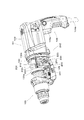
次に図1および図2に基づき、本体ハウジング101の内部において工具ビット119を駆動する先端工具駆動機構の構成を説明する。図2は先端工具駆動機構を説明するための拡大断面図である。
図1に示す通り先端工具駆動機構は、工具ビット119を直線状に駆動するための運動変換機構120および打撃要素140と、工具ビット119を回転駆動するための回転伝達機構150とを主体として構成される。この運動変換機構120および打撃要素140により構成される機構が本発明に係る「先端工具駆動機構」の一例である。 (Advanced tool drive mechanism)
Next, based on FIG. 1 and FIG. 2, the structure of the tip tool drive mechanism which drives thetool bit 119 inside the main body housing 101 is demonstrated. FIG. 2 is an enlarged cross-sectional view for explaining the tip tool driving mechanism.
As shown in FIG. 1, the tip tool driving mechanism mainly includes amotion conversion mechanism 120 and a striking element 140 for driving the tool bit 119 in a straight line, and a rotation transmission mechanism 150 for rotating the tool bit 119. Is done. The mechanism constituted by the motion conversion mechanism 120 and the striking element 140 is an example of the “tip tool driving mechanism” according to the present invention.
次に図1および図2に基づき、本体ハウジング101の内部において工具ビット119を駆動する先端工具駆動機構の構成を説明する。図2は先端工具駆動機構を説明するための拡大断面図である。
図1に示す通り先端工具駆動機構は、工具ビット119を直線状に駆動するための運動変換機構120および打撃要素140と、工具ビット119を回転駆動するための回転伝達機構150とを主体として構成される。この運動変換機構120および打撃要素140により構成される機構が本発明に係る「先端工具駆動機構」の一例である。 (Advanced tool drive mechanism)
Next, based on FIG. 1 and FIG. 2, the structure of the tip tool drive mechanism which drives the
As shown in FIG. 1, the tip tool driving mechanism mainly includes a
(回転伝達機構)
図1に示す通り、回転伝達機構150は回転軸116cを中心として回転可能な中間軸部116を有する。回転軸116cは、駆動モータ110の出力軸部111および後述する先端工具駆動機構により規定される駆動軸140aと平行である。この中間軸部116が本発明に係る「回転軸部材」の一例であり、回転軸116cが本発明に係る「回転軸」の一例である。
図1に示す通り、中間軸部116の前側はベアリング116aを介して、後側はベアリング116bを介してそれぞれギアハウジング105に取り付けられる。中間軸部116の後側には、駆動モータ110のピニオンギア113と噛み合う被動ギア117が設けられ、前側にはスリーブ129と一体化された第2ギア153と噛み合う第1ギア151が設けられる。 (Rotation transmission mechanism)
As shown in FIG. 1, therotation transmission mechanism 150 includes an intermediate shaft portion 116 that can rotate around a rotation shaft 116 c. The rotation shaft 116c is parallel to the output shaft 111 of the drive motor 110 and a drive shaft 140a defined by a tip tool drive mechanism described later. The intermediate shaft 116 is an example of the “rotary shaft member” according to the present invention, and the rotational shaft 116c is an example of the “rotating shaft” according to the present invention.
As shown in FIG. 1, the front side of theintermediate shaft portion 116 is attached to the gear housing 105 via a bearing 116a, and the rear side is attached to the gear housing 105 via a bearing 116b. A driven gear 117 that meshes with the pinion gear 113 of the drive motor 110 is provided on the rear side of the intermediate shaft portion 116, and a first gear 151 that meshes with the second gear 153 integrated with the sleeve 129 is provided on the front side.
図1に示す通り、回転伝達機構150は回転軸116cを中心として回転可能な中間軸部116を有する。回転軸116cは、駆動モータ110の出力軸部111および後述する先端工具駆動機構により規定される駆動軸140aと平行である。この中間軸部116が本発明に係る「回転軸部材」の一例であり、回転軸116cが本発明に係る「回転軸」の一例である。
図1に示す通り、中間軸部116の前側はベアリング116aを介して、後側はベアリング116bを介してそれぞれギアハウジング105に取り付けられる。中間軸部116の後側には、駆動モータ110のピニオンギア113と噛み合う被動ギア117が設けられ、前側にはスリーブ129と一体化された第2ギア153と噛み合う第1ギア151が設けられる。 (Rotation transmission mechanism)
As shown in FIG. 1, the
As shown in FIG. 1, the front side of the
なお図1に示す通り、スリーブ129は、リングスプリング159aを介してツールホルダ159と接続されることにより当該ツールホルダ159と一体化している。またスリーブ129は、前側がベアリング129aを介してギアハウジング105に取り付けられ、後側がベアリング129bを介してインナーハウジング130に取り付けられることにより、本体ハウジング101内において回動自在に配置されている。
当該構成によって、ピニオンギア113の出力が被動ギア117に伝達され中間軸部116が回転される。そして、中間軸部116の回転が第1ギア151および第2ギア153を介してスリーブ129に伝達され、ツールホルダ159とともに工具ビット119が回転駆動される。 As shown in FIG. 1, thesleeve 129 is integrated with the tool holder 159 by being connected to the tool holder 159 via a ring spring 159a. Further, the sleeve 129 is rotatably disposed in the main body housing 101 by being attached to the gear housing 105 on the front side via the bearing 129a and attached to the inner housing 130 via the bearing 129b.
With this configuration, the output of thepinion gear 113 is transmitted to the driven gear 117, and the intermediate shaft portion 116 is rotated. Then, the rotation of the intermediate shaft portion 116 is transmitted to the sleeve 129 via the first gear 151 and the second gear 153, and the tool bit 119 is rotationally driven together with the tool holder 159.
当該構成によって、ピニオンギア113の出力が被動ギア117に伝達され中間軸部116が回転される。そして、中間軸部116の回転が第1ギア151および第2ギア153を介してスリーブ129に伝達され、ツールホルダ159とともに工具ビット119が回転駆動される。 As shown in FIG. 1, the
With this configuration, the output of the
(運動変換機構および打撃要素)
図2に示す通り、運動変換機構120は、クラッチカム180と、回転体123と、揺動軸部125とを主体にして構成される。回転体123は、中間軸部116に対し回動自在に構成される。クラッチカム180は中間軸部116に対しスプライン結合されており、回転軸116c方向に移動可能であるとともに中間軸部116の回転に伴い回動される。 (Motion conversion mechanism and striking element)
As shown in FIG. 2, themotion conversion mechanism 120 is mainly configured by a clutch cam 180, a rotating body 123, and a swing shaft portion 125. The rotating body 123 is configured to be rotatable with respect to the intermediate shaft portion 116. Clutch cam 180 is splined to intermediate shaft portion 116, is movable in the direction of rotating shaft 116 c, and is rotated as intermediate shaft portion 116 rotates.
図2に示す通り、運動変換機構120は、クラッチカム180と、回転体123と、揺動軸部125とを主体にして構成される。回転体123は、中間軸部116に対し回動自在に構成される。クラッチカム180は中間軸部116に対しスプライン結合されており、回転軸116c方向に移動可能であるとともに中間軸部116の回転に伴い回動される。 (Motion conversion mechanism and striking element)
As shown in FIG. 2, the
より具体的には、クラッチカム180は、使用者によるモードチェンジレバーの動作に連動して前後方向へ移動される。なお、モードチェンジレバーの詳細については便宜上省略する。
モードチェンジレバーがハンマドリルモードを選択した場合は、クラッチカム180が後側に移動され、クラッチカム180のクラッチ歯180aと回転体123のクラッチ歯123aが噛み合う。よってこの場合は、ツールホルダ159が回転駆動されるとともに回転体123が回転され、後述する通りピストン127が駆動される。
一方、モードチェンジレバーがドリルモードを選択した場合は、クラッチカム180が前側に移動され、クラッチ歯180aおよびクラッチ歯123aの噛み合いが解除される。よってこの場合は、ツールホルダ159が回転駆動される一方で、中間軸部116の回転が回転体123に伝達されずピストン127が駆動されない。なお、図1および図2は、ドリルモードが選択された状態を示している。 More specifically, theclutch cam 180 is moved in the front-rear direction in conjunction with the operation of the mode change lever by the user. Details of the mode change lever are omitted for convenience.
When the mode change lever selects the hammer drill mode, theclutch cam 180 is moved to the rear side, and the clutch teeth 180a of the clutch cam 180 and the clutch teeth 123a of the rotating body 123 are engaged. Therefore, in this case, the tool holder 159 is rotated and the rotating body 123 is rotated, and the piston 127 is driven as described later.
On the other hand, when the mode change lever selects the drill mode, theclutch cam 180 is moved forward, and the engagement of the clutch teeth 180a and the clutch teeth 123a is released. Therefore, in this case, while the tool holder 159 is rotationally driven, the rotation of the intermediate shaft portion 116 is not transmitted to the rotating body 123 and the piston 127 is not driven. 1 and 2 show a state in which the drill mode is selected.
モードチェンジレバーがハンマドリルモードを選択した場合は、クラッチカム180が後側に移動され、クラッチカム180のクラッチ歯180aと回転体123のクラッチ歯123aが噛み合う。よってこの場合は、ツールホルダ159が回転駆動されるとともに回転体123が回転され、後述する通りピストン127が駆動される。
一方、モードチェンジレバーがドリルモードを選択した場合は、クラッチカム180が前側に移動され、クラッチ歯180aおよびクラッチ歯123aの噛み合いが解除される。よってこの場合は、ツールホルダ159が回転駆動される一方で、中間軸部116の回転が回転体123に伝達されずピストン127が駆動されない。なお、図1および図2は、ドリルモードが選択された状態を示している。 More specifically, the
When the mode change lever selects the hammer drill mode, the
On the other hand, when the mode change lever selects the drill mode, the
図2に示す通り、回転体123は、回転軸116aに対して所定の傾斜角度を有する外周面123cを有する。揺動軸部125は、回転体123の外周面123cに対し複数のスチールボール123bを介して取付けられるとともに回転体123の周囲を包囲する環状部125bと、環状部125bから上方へ突出して設けられるとともにジョイントピン126を介してピストン127と接続される軸部125aと、環状部125bにおける軸部125aとは対向する側(下側)から下方へ突出して設けられるとともに後述する連結部材250と接続される凸部125cとを有する。なお、軸部125aとジョイントピン127とは相対的に回動可能に接続され、先端工具駆動機構接続部を構成する。また、凸部125cと連結部材250は相対的に回動可能に接続され、連結部材接続機構を構成する。この揺動軸部125が本発明に係る「揺動部材」の一例である。当該構成によって、回転体123の回転に伴う外周面123cの傾斜角度の移行に環状部125bが追随することにより、軸部123aが回転軸123に沿った前後方向にて揺動される。この軸部123aの揺動動作における直線運動成分によって、後述する通り先端工具駆動機構が駆動される。
なお軸部125aと凸部125cとは、回転軸116cに対して互いに対向する位置関係となる。よって、軸部125aが前側に向けられた場合は、凸部125cは後側へ向けられる。また、軸部125aが後側に向けられた場合は、凸部125cは前側へ向けられる。 As shown in FIG. 2, therotating body 123 has an outer peripheral surface 123c having a predetermined inclination angle with respect to the rotating shaft 116a. The swing shaft portion 125 is attached to the outer peripheral surface 123c of the rotating body 123 via a plurality of steel balls 123b and is provided so as to protrude upward from the annular portion 125b and an annular portion 125b that surrounds the periphery of the rotating body 123. The shaft portion 125a connected to the piston 127 via the joint pin 126 and the shaft portion 125a in the annular portion 125b are provided to project downward from the opposite side (lower side) and are connected to a connecting member 250 described later. And a convex portion 125c. The shaft portion 125a and the joint pin 127 are connected so as to be relatively rotatable, and constitute a tip tool drive mechanism connection portion. Moreover, the convex part 125c and the connection member 250 are connected so that rotation is relatively possible, and comprise the connection member connection mechanism. The swing shaft portion 125 is an example of the “swing member” according to the present invention. With this configuration, the annular portion 125 b follows the transition of the inclination angle of the outer peripheral surface 123 c accompanying the rotation of the rotating body 123, so that the shaft portion 123 a is swung in the front-rear direction along the rotation shaft 123. The tip tool driving mechanism is driven by a linear motion component in the swinging motion of the shaft portion 123a as described later.
Theshaft portion 125a and the convex portion 125c are in a positional relationship facing each other with respect to the rotation shaft 116c. Therefore, when the shaft portion 125a is directed to the front side, the convex portion 125c is directed to the rear side. Further, when the shaft portion 125a is directed to the rear side, the convex portion 125c is directed to the front side.
なお軸部125aと凸部125cとは、回転軸116cに対して互いに対向する位置関係となる。よって、軸部125aが前側に向けられた場合は、凸部125cは後側へ向けられる。また、軸部125aが後側に向けられた場合は、凸部125cは前側へ向けられる。 As shown in FIG. 2, the
The
図2に示す通り、打撃要素140は、スリーブ129の内筒に摺動自在に配置された有底の筒状部材によるピストン127と、ピストン127の内筒に摺動自在に配置された打撃子としてのストライカ143と、ツールホルダ159の内筒に摺動自在に配置されるとともにストライカ143の運動エネルギーを工具ビット119に伝達する中間子としてのインパクトボルト145を主体として構成される。
As shown in FIG. 2, the striking element 140 includes a piston 127 formed of a bottomed tubular member slidably disposed on the inner cylinder of the sleeve 129, and a striking element slidably disposed on the inner cylinder of the piston 127. And an impact bolt 145 serving as an intermediate for transmitting the kinetic energy of the striker 143 to the tool bit 119.
ピストン127の底部と、ストライカ143との間には空気室127aが形成されており、ストライカ143はピストン127がスリーブ129内を往復運動することに伴う空気室127a内の圧力変動により直線状に駆動される。すなわち、ピストン127が前側へ移動して空気室127aのエアを圧縮した場合には、当該圧縮されたエアの膨張に伴いストライカ143が前側に押し出されてインパクトボルト145に衝突し、工具ビット119を前側に移動させる。一方、ピストン127が後側に移動した場合には空気室127aのエアが膨張される。この膨張したエアの負圧に伴いストライカ143が後側に引き込まれる。なお加工作業の際には、工具ビット119の先端が使用者によって押圧される。これによって、工具ビット119の後端に押されてインパクトボルト145が後側へ移動される。後側に移動されたインパクトボルト145は、上述した通りピストン127の前側への移動に伴って前側へ移動され、工具ビット119に衝突する。この一連の動作を繰り返すことにより、工具ビット119が直線状に連続的に駆動される。なお、上述した打撃要素140の動作は、図1に示される打撃軸140aを規定する。打撃軸140aは回転軸116cと平行である。この打撃軸140aが本発明に係る「駆動軸」の一例である。
An air chamber 127a is formed between the bottom of the piston 127 and the striker 143. The striker 143 is linearly driven by pressure fluctuations in the air chamber 127a as the piston 127 reciprocates in the sleeve 129. Is done. That is, when the piston 127 moves forward and compresses the air in the air chamber 127a, the striker 143 is pushed forward and collides with the impact bolt 145 as the compressed air expands. Move to the front side. On the other hand, when the piston 127 moves to the rear side, the air in the air chamber 127a is expanded. The striker 143 is pulled back with the negative pressure of the expanded air. During the machining operation, the tip of the tool bit 119 is pressed by the user. As a result, the impact bolt 145 is moved to the rear side by being pushed by the rear end of the tool bit 119. The impact bolt 145 moved to the rear side is moved to the front side as the piston 127 moves to the front side as described above, and collides with the tool bit 119. By repeating this series of operations, the tool bit 119 is continuously driven linearly. The operation of the hitting element 140 described above defines the hitting shaft 140a shown in FIG. The striking shaft 140a is parallel to the rotation shaft 116c. The striking shaft 140a is an example of the “drive shaft” according to the present invention.
(制振機構)
次に、図3~図10に基づき制振機構200の構成を説明する。図3は、制振機構200の要部を示す説明図である。図3に示す通り制振機構200は、動吸振器210と連結部材250とを有する。この制振機構200が本発明に係る「制振機構」の一例であり、動吸振器210が本発明に係る「動吸振器」の一例であり、連結部材250が本発明に係る「連結部材」の一例である。 (Vibration control mechanism)
Next, the configuration of thevibration damping mechanism 200 will be described with reference to FIGS. FIG. 3 is an explanatory diagram showing a main part of the vibration damping mechanism 200. As shown in FIG. 3, the vibration damping mechanism 200 includes a dynamic vibration absorber 210 and a connecting member 250. The vibration damping mechanism 200 is an example of the “vibration damping mechanism” according to the present invention, the dynamic vibration absorber 210 is an example of the “dynamic vibration absorber” according to the present invention, and the connection member 250 is the “connection member” according to the present invention. Is an example.
次に、図3~図10に基づき制振機構200の構成を説明する。図3は、制振機構200の要部を示す説明図である。図3に示す通り制振機構200は、動吸振器210と連結部材250とを有する。この制振機構200が本発明に係る「制振機構」の一例であり、動吸振器210が本発明に係る「動吸振器」の一例であり、連結部材250が本発明に係る「連結部材」の一例である。 (Vibration control mechanism)
Next, the configuration of the
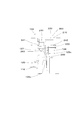
図4は、図1におけるI-I線断面図である。図4に示す通り、動吸振器210は、インナーハウジング130の前部130aとインナーハウジング130の後部130bに亘り配置された複数のシャフト220と、当該シャフト220に挿通されたウェイト230と、当該ウェイト230を付勢する弾性部材240とを有する。図6に示す通り、シャフト220は5つ使用されているが、シャフト220の数は実現すべき動吸振器210の構成により任意の数を選択することができる。またシャフト220の延在方向は、打撃軸140aと平行とされる。ウェイト230は挿通孔部230aを有し、当該挿通孔部230aにシャフト220が貫通される。このシャフト220が本発明に係る「シャフト」の一例であり、ウェイト230が本発明に係る「ウェイト」の一例であり、弾性部材240が本発明に係る「弾性部材」の一例である。
FIG. 4 is a cross-sectional view taken along line II in FIG. As shown in FIG. 4, the dynamic vibration absorber 210 includes a plurality of shafts 220 arranged over the front portion 130 a of the inner housing 130 and the rear portion 130 b of the inner housing 130, a weight 230 inserted through the shaft 220, and the weight And an elastic member 240 for urging 230. As shown in FIG. 6, five shafts 220 are used, but the number of shafts 220 can be selected according to the configuration of the dynamic vibration absorber 210 to be realized. The extending direction of the shaft 220 is parallel to the striking shaft 140a. The weight 230 has an insertion hole 230a, and the shaft 220 passes through the insertion hole 230a. The shaft 220 is an example of the “shaft” according to the present invention, the weight 230 is an example of the “weight” according to the present invention, and the elastic member 240 is an example of the “elastic member” according to the present invention.
図4に示す通り、弾性部材240は、複数のシャフト220の内の一部のシャフト220に配置されていれば足りる。本実施形態において、弾性部材240は打撃軸140aを挟んで対向する位置にある一対のシャフト上220に配置されている。図5は、弾性部材240が配置されたシャフト220の説明図である。弾性部材240は、インナーハウジング130の前部130aとウェイト230の前側の間に配置された第1弾性部材241と、インナーハウジング130の後部130bとウェイト230の後側の間に配置された第2弾性部材242とを有する。当該構成によって、ウェイト230はシャフト220に対して往復摺動することが可能となる。
As shown in FIG. 4, it is sufficient that the elastic member 240 is disposed on a part of the plurality of shafts 220. In the present embodiment, the elastic member 240 is disposed on the pair of shafts 220 at positions facing each other across the striking shaft 140a. FIG. 5 is an explanatory diagram of the shaft 220 on which the elastic member 240 is arranged. The elastic member 240 includes a first elastic member 241 disposed between the front portion 130a of the inner housing 130 and the front side of the weight 230, and a second elastic member 240 disposed between the rear portion 130b of the inner housing 130 and the rear side of the weight 230. And an elastic member 242. With this configuration, the weight 230 can reciprocate with respect to the shaft 220.
図6は、図1におけるII-II線断面図である。図6に示す通り、ウェイト230は、打撃軸140a周りにおいて打撃軸140aを包囲している。当該構成により、打撃要素140が駆動された場合における打撃軸140aに沿った方向の振動により、ウェイト230が往復移動を行いやすくなる。すなわち動吸振器210は、打撃軸140a方向の振動を効果的に抑制することが可能となる。なお、ウェイト230は、端部を含む領域として一対の端部領域231を有する。当該一対の端部領域231の間の領域は中間領域232を構成する。
FIG. 6 is a cross-sectional view taken along line II-II in FIG. As shown in FIG. 6, the weight 230 surrounds the hitting shaft 140a around the hitting shaft 140a. With this configuration, the weight 230 can easily reciprocate due to vibration in the direction along the striking shaft 140a when the striking element 140 is driven. That is, the dynamic vibration absorber 210 can effectively suppress vibration in the direction of the striking shaft 140a. In addition, the weight 230 has a pair of end part area | region 231 as an area | region including an end part. A region between the pair of end regions 231 constitutes an intermediate region 232.
図6に示す通り、連結部材250は、回転軸116c周りにおいて回転軸116cを包囲している。当該構成により、連結部材250を中間軸部116の周囲に効率よく配置することが可能となる。また、連結部材250は、端部を含む領域として一対の端部領域251を有する。当該一対の端部領域251の間の領域は中間領域252を構成する。この端部領域251が本発明に係る「端部領域」の一例であり、中間領域252が本発明に係る「中間領域」の一例である。
連結部材250の端部領域251は、支点軸260aを中心にウェイト230の端部領域231と相対的に回動可能に接続される。なお、連結部材250とウェイト230の具体的な接続構造については後述する。連結部材250の中間領域252は中間孔部252aを有し、当該中間孔部252aには揺動軸部125の凸部125cが挿通される。当該構成によって、連結部材250は揺動軸部125の回動動作に伴い前後方向に移動される。 As shown in FIG. 6, the connectingmember 250 surrounds the rotation shaft 116c around the rotation shaft 116c. With this configuration, the connecting member 250 can be efficiently arranged around the intermediate shaft portion 116. Moreover, the connection member 250 has a pair of edge part area | region 251 as an area | region including an edge part. A region between the pair of end regions 251 constitutes an intermediate region 252. The end region 251 is an example of the “end region” according to the present invention, and the intermediate region 252 is an example of the “intermediate region” according to the present invention.
Theend region 251 of the connecting member 250 is connected to the end region 231 of the weight 230 so as to be rotatable about the fulcrum shaft 260a. A specific connection structure between the connecting member 250 and the weight 230 will be described later. The intermediate region 252 of the connecting member 250 has an intermediate hole portion 252a, and the convex portion 125c of the swing shaft portion 125 is inserted into the intermediate hole portion 252a. With this configuration, the connecting member 250 is moved in the front-rear direction as the swinging shaft portion 125 rotates.
連結部材250の端部領域251は、支点軸260aを中心にウェイト230の端部領域231と相対的に回動可能に接続される。なお、連結部材250とウェイト230の具体的な接続構造については後述する。連結部材250の中間領域252は中間孔部252aを有し、当該中間孔部252aには揺動軸部125の凸部125cが挿通される。当該構成によって、連結部材250は揺動軸部125の回動動作に伴い前後方向に移動される。 As shown in FIG. 6, the connecting
The
図7は、ウェイト230と連結部材250の接続構造を示す説明図である。図7に示す通り、ウェイト230の端部領域231に形成された端部孔部231aと、連結部材250の端部領域251に形成された端部孔部251aには円柱状の支点軸部260が装着される。支点軸部260における連結部材250の外側領域には凹部が形成されており、当該凹部には連結部材250の抜け防止のための止めリング261が装着される。当該構成により、ウェイト230と連結部材250は、支点軸260aを中心に相対的に回動可能に構成される。この支点軸260aが本発明に係る「支点軸」の一例である。
FIG. 7 is an explanatory diagram showing a connection structure between the weight 230 and the connecting member 250. As shown in FIG. 7, a cylindrical fulcrum shaft portion 260 is formed in the end hole portion 231 a formed in the end region 231 of the weight 230 and the end hole portion 251 a formed in the end region 251 of the connecting member 250. Is installed. A recessed portion is formed in the outer region of the connecting member 250 in the fulcrum shaft portion 260, and a retaining ring 261 for preventing the connecting member 250 from coming off is attached to the recessed portion. With this configuration, the weight 230 and the connecting member 250 are configured to be relatively rotatable about the fulcrum shaft 260a. This fulcrum shaft 260a is an example of the “fulcrum shaft” according to the present invention.
次に図8~図10に基づき、制振機構200の動作につき説明する。図8は、揺動軸部125の軸部125aの延在方向が回転軸116cと直交する方向に置かれた状態を示す。説明の便宜上、図8に示された制振機構200の状態を第1状態とする。図8に示す通り、一対の支点軸部260間における中心点と、連結部材250の中間孔部252aの中心点とを結ぶ中心線250aは、当該中心線250aを通過するとともに回転軸116cと直交する回転軸直交線116dに対して所定の傾斜角度を有する。より具体的には、支点軸部260は中間孔部252aよりも後側に配置される。支点軸部260と中間孔部252とがこのような配置形態であるため、連結部材250は、端部領域251と中間領域252とに亘る連絡領域253を有する。連結部材250が当該構成を有することにより、限られた空間内に連結部材250を効率よく配置することができ、結果としてハンマドリル100の小型化を図ることが可能となる。
Next, the operation of the vibration damping mechanism 200 will be described with reference to FIGS. FIG. 8 shows a state in which the extending direction of the shaft portion 125a of the swing shaft portion 125 is placed in a direction orthogonal to the rotation shaft 116c. For convenience of explanation, the state of the vibration damping mechanism 200 shown in FIG. As shown in FIG. 8, a center line 250a connecting the center point between the pair of fulcrum shaft portions 260 and the center point of the intermediate hole portion 252a of the connecting member 250 passes through the center line 250a and is orthogonal to the rotation shaft 116c. And a predetermined inclination angle with respect to the rotating axis orthogonal line 116d. More specifically, the fulcrum shaft portion 260 is disposed behind the intermediate hole portion 252a. Since the fulcrum shaft portion 260 and the intermediate hole portion 252 are arranged in this manner, the connecting member 250 has a communication region 253 that extends between the end region 251 and the intermediate region 252. Since the connecting member 250 has the configuration, the connecting member 250 can be efficiently arranged in a limited space, and as a result, the hammer drill 100 can be downsized.
説明の便宜上、図8に示した第1状態を制振機構200の初期状態とする。まず、当該初期状態において、使用者がドリルモードを選択した場合を説明する。この場合、回転伝達機構150の駆動に伴う振動や使用者のハンマドリル100の操作に伴う振動によって、ウェイト230は連結部材250とともに往復移動されて当該振動を抑制する。この場合、ウェイト230はシャフト220上に摺動することにより直線状に往復移動する。また連結部材250は、ウェイト230の直線状の往復移動に伴う支点軸部260の往復移動によって中間孔部252aを中心とした回動動作を行う。
For convenience of explanation, the first state shown in FIG. First, a case where the user selects the drill mode in the initial state will be described. In this case, the weight 230 is reciprocated together with the connecting member 250 by the vibration accompanying the driving of the rotation transmission mechanism 150 and the vibration accompanying the operation of the hammer drill 100 by the user, thereby suppressing the vibration. In this case, the weight 230 reciprocates linearly by sliding on the shaft 220. The connecting member 250 rotates around the intermediate hole 252a by the reciprocating movement of the fulcrum shaft 260 along with the linear reciprocating movement of the weight 230.
次に使用者がハンマドリルモードを選択した場合を説明する。上述の通りハンマドリルモードにあっては、中間軸部116の回転に伴い揺動軸部125が揺動される。図9は、中間軸部116の回転に伴い軸部125aが前側へ傾斜された状態を示す。この状態の制振機構200を第2状態とする。
第2状態においては、軸部125aがピストン127を前側へ移動することにより工具ビット119が前側へ移動される。一方、凸部125cが後側へ傾斜されるため、連結部材250を介してウェイト230が後側へ移動される。この場合、第1弾性部材241がウェイト230を付勢することにより、ウェイト230の後方移動が補助される。なお、ウェイト230により第2弾性部材242が圧縮される。 Next, a case where the user selects the hammer drill mode will be described. As described above, in the hammer drill mode, the swingingshaft portion 125 is swung as the intermediate shaft portion 116 rotates. FIG. 9 shows a state in which the shaft portion 125a is inclined forward as the intermediate shaft portion 116 rotates. The vibration damping mechanism 200 in this state is set to the second state.
In the second state, thetool bit 119 is moved to the front side by the shaft portion 125a moving the piston 127 to the front side. On the other hand, since the convex portion 125c is inclined rearward, the weight 230 is moved rearward via the connecting member 250. In this case, the first elastic member 241 urges the weight 230 to assist the backward movement of the weight 230. Note that the second elastic member 242 is compressed by the weight 230.
第2状態においては、軸部125aがピストン127を前側へ移動することにより工具ビット119が前側へ移動される。一方、凸部125cが後側へ傾斜されるため、連結部材250を介してウェイト230が後側へ移動される。この場合、第1弾性部材241がウェイト230を付勢することにより、ウェイト230の後方移動が補助される。なお、ウェイト230により第2弾性部材242が圧縮される。 Next, a case where the user selects the hammer drill mode will be described. As described above, in the hammer drill mode, the swinging
In the second state, the
回転軸部116の回転に伴い揺動軸部125は、第2状態から第1状態を経て、図10に示される軸部125aが後側に傾斜した状態へと揺動される。この状態の制振機構200を第3状態とする。
第3状態においては、軸部125aが後側へ傾斜するとともに凸部125cが前側に傾斜される。よって、軸部125aがピストン127を後側へ移動し、これに伴い空気室127a内のエアが膨張されてストライカ143が後側へ移動される。なお、使用者は工具ビット119を被加工材に押し付けているため、工具ビット119はインパクトボルト145とともに後側へ移動される。
一方、凸部125cが前側へ傾斜されるため、連結部材250を介してウェイト230が前側へ移動される。この場合、第2弾性部材242がウェイト230を付勢することにより、ウェイト230の前方移動が補助される。なお、ウェイト230により第1弾性部材241が圧縮される。 As therotary shaft 116 rotates, the swing shaft 125 swings from the second state to the state where the shaft 125a shown in FIG. 10 is inclined rearward through the first state. The vibration damping mechanism 200 in this state is set to the third state.
In the third state, theshaft portion 125a is inclined to the rear side, and the convex portion 125c is inclined to the front side. Therefore, the shaft part 125a moves the piston 127 to the rear side, and accordingly, the air in the air chamber 127a is expanded and the striker 143 is moved to the rear side. Since the user presses the tool bit 119 against the workpiece, the tool bit 119 is moved rearward together with the impact bolt 145.
On the other hand, since theconvex part 125c is inclined to the front side, the weight 230 is moved to the front side via the connecting member 250. In this case, the second elastic member 242 urges the weight 230 to assist the forward movement of the weight 230. Note that the first elastic member 241 is compressed by the weight 230.
第3状態においては、軸部125aが後側へ傾斜するとともに凸部125cが前側に傾斜される。よって、軸部125aがピストン127を後側へ移動し、これに伴い空気室127a内のエアが膨張されてストライカ143が後側へ移動される。なお、使用者は工具ビット119を被加工材に押し付けているため、工具ビット119はインパクトボルト145とともに後側へ移動される。
一方、凸部125cが前側へ傾斜されるため、連結部材250を介してウェイト230が前側へ移動される。この場合、第2弾性部材242がウェイト230を付勢することにより、ウェイト230の前方移動が補助される。なお、ウェイト230により第1弾性部材241が圧縮される。 As the
In the third state, the
On the other hand, since the
図8~図10に基づき説明を行った通り、制振機構200は、第1状態を経由した第2状態と第3状態との間において、揺動軸部125の揺動動作に基づきウェイト230を直接的かつ強制的に往復移動させるよう構成されている。よって、制振機構200はウェイト強制往復移動機構を有するということができる。
As described with reference to FIGS. 8 to 10, the vibration damping mechanism 200 has the weight 230 based on the swinging motion of the swinging shaft portion 125 between the second state and the third state via the first state. Is configured to reciprocate directly and forcibly. Therefore, it can be said that the vibration control mechanism 200 has a weight forced reciprocation mechanism.
さらに、制振機構200は、揺動軸部125の揺動に伴いウェイト230を強制的に移動するものであることから、ウェイト230が静止している状態から移動する状態に移行させるための補助機構ということができる。
また、ウェイト230と弾性部材240のみにより構成される動吸振器210においては、ウェイト230は本体ハウジング101に発生する振動のみにより往復移動される。よって、ウェイト230が往復移動する距離は本体ハウジング101に対する振動の大きさに依存される。
一方、本発明に係る制振機構200においては、連結部材250を介してウェイト230を上述した第2状態と第3状態との間で強制的に往復移動させるものである。すなわち、制振機構200は、ウェイト230と弾性部材240のみにより構成される動吸振器210におけるウェイト230の往復移動量が少ない状況に対しては、ウェイト230における往復移動量の増加機構を構成するということができる。一方、制振機構200は、ウェイト230と弾性部材240のみにより構成される動吸振器210におけるウェイト230の往復移動量が多い状況に対しては、ウェイト230における往復移動量の調整機構を構成するということができる。 Furthermore, since thevibration damping mechanism 200 forcibly moves the weight 230 as the rocking shaft portion 125 swings, the vibration control mechanism 200 is an assist for shifting the weight 230 from a stationary state to a moving state. It can be called a mechanism.
Further, in thedynamic vibration absorber 210 including only the weight 230 and the elastic member 240, the weight 230 is reciprocated only by vibration generated in the main body housing 101. Therefore, the distance that the weight 230 reciprocates depends on the magnitude of vibration with respect to the main body housing 101.
On the other hand, in thevibration damping mechanism 200 according to the present invention, the weight 230 is forcibly reciprocated between the second state and the third state described above via the connecting member 250. That is, the vibration damping mechanism 200 constitutes a mechanism for increasing the amount of reciprocating movement of the weight 230 in a situation where the amount of reciprocating movement of the weight 230 in the dynamic vibration absorber 210 including only the weight 230 and the elastic member 240 is small. It can be said. On the other hand, the vibration control mechanism 200 constitutes a mechanism for adjusting the amount of reciprocation of the weight 230 in a situation where the amount of reciprocation of the weight 230 in the dynamic vibration absorber 210 including only the weight 230 and the elastic member 240 is large. It can be said.
また、ウェイト230と弾性部材240のみにより構成される動吸振器210においては、ウェイト230は本体ハウジング101に発生する振動のみにより往復移動される。よって、ウェイト230が往復移動する距離は本体ハウジング101に対する振動の大きさに依存される。
一方、本発明に係る制振機構200においては、連結部材250を介してウェイト230を上述した第2状態と第3状態との間で強制的に往復移動させるものである。すなわち、制振機構200は、ウェイト230と弾性部材240のみにより構成される動吸振器210におけるウェイト230の往復移動量が少ない状況に対しては、ウェイト230における往復移動量の増加機構を構成するということができる。一方、制振機構200は、ウェイト230と弾性部材240のみにより構成される動吸振器210におけるウェイト230の往復移動量が多い状況に対しては、ウェイト230における往復移動量の調整機構を構成するということができる。 Furthermore, since the
Further, in the
On the other hand, in the
また、本発明に係る制振機構200における連結部材250は、ウェイト230と揺動軸部125の双方に対して回動可能に構成されているため、揺動軸部125の揺動動作に伴ってウェイト230を直線状に往復移動させることができる。また、連結部材250がウェイト230と揺動軸部125の双方に対して回動可能であることにより、制振機構200がウェイト230の往復移動における位相変更機構を構成するということができる。
Further, since the connecting member 250 in the vibration damping mechanism 200 according to the present invention is configured to be rotatable with respect to both the weight 230 and the swinging shaft portion 125, the swinging member 125 is swung with the swinging motion. Thus, the weight 230 can be reciprocated linearly. Further, since the connecting member 250 is rotatable with respect to both the weight 230 and the swing shaft portion 125, it can be said that the vibration control mechanism 200 constitutes a phase changing mechanism in the reciprocating movement of the weight 230.
また、連結部材250は、揺動軸部250の揺動動作に伴い往復移動されるため、カウンタウェイトを構成すると言うことができる。
すなわち本発明に係る制振機構200は、種々の機能を兼用することにより、実現しようとする作業工具100に適した制振機構200を構成することが可能となる。 Further, it can be said that the connectingmember 250 constitutes a counterweight because it is reciprocated with the swinging motion of the swinging shaft portion 250.
That is, thevibration damping mechanism 200 according to the present invention can configure the vibration damping mechanism 200 suitable for the work tool 100 to be realized by combining various functions.
すなわち本発明に係る制振機構200は、種々の機能を兼用することにより、実現しようとする作業工具100に適した制振機構200を構成することが可能となる。 Further, it can be said that the connecting
That is, the
以上、実施形態の一例を説明したが本発明に係る作業工具の構成として他の構成を使用することが可能である。例えば、作業工具として先端工具を直線状に駆動することにより木材などの被加工材に対し切断作業を行う電動レシプロソーを用いることが可能である。また、ハンドグリップ109は下方に延在する片持ち梁状に形成されていたが、ハンドグリップ109をループ状に形成することも可能である。また、電動モータ110の出力軸部111が回転軸116cと平行に配置されていたが、電動モータ110の出力軸部111を回転軸116cと交差するように配置してもよい。この場合には、出力軸部111と中間軸部116はベベルギアを介して係合することが好ましい。
As mentioned above, although an example of embodiment was explained, it is possible to use other composition as composition of a work tool concerning the present invention. For example, it is possible to use an electric reciprocating saw that performs a cutting operation on a workpiece such as wood by driving a tip tool linearly as a work tool. Further, although the hand grip 109 is formed in a cantilever shape extending downward, the hand grip 109 may be formed in a loop shape. Further, although the output shaft portion 111 of the electric motor 110 is disposed in parallel with the rotation shaft 116c, the output shaft portion 111 of the electric motor 110 may be disposed so as to intersect the rotation shaft 116c. In this case, the output shaft portion 111 and the intermediate shaft portion 116 are preferably engaged via a bevel gear.
以上の発明の趣旨に鑑み、本発明に係る作業工具は、下記の態様が構成可能である。なお、各態様は、単独で、あるいは互いに組み合わされて用いられるだけでなく、請求項に記載された発明と組み合わされて用いられる。
(態様1)
前記回転軸部材は、前記回転軸に対して所定の傾斜角度を有する外周面を備えた回転体を有し、
前記揺動軸部は、前記外周面に対し相対的に回動可能に配置された環状部と、前記環状部から突出して設けられるとともに前記先端工具駆動機構に対して相対的に回動可能に接続された軸部と、前記環状部における前記軸部とは対向する側から突出して設けられるとともに前記連結部材に対して回動可能に接続された凸部とを有することを特徴とする。
(態様2)
前記制振機構は、前記揺動部材と前記先端工具駆動機構とを相対的に回動自在に接続する第1接続部と、前記揺動部材と前記連結部材とを相対的に回動自在に接続する第2接続部とを有することを特徴とする。
(態様3)
前記第1接続部と前記第2接続部は、前記回動軸を挟んで互いに対向する位置に置くことが可能であることを特徴とする。 In view of the gist of the above invention, the working tool according to the present invention can be configured in the following manner. Each aspect is used not only alone or in combination with each other, but also in combination with the invention described in the claims.
(Aspect 1)
The rotating shaft member includes a rotating body having an outer peripheral surface having a predetermined inclination angle with respect to the rotating shaft,
The swinging shaft portion is provided so as to be rotatable relative to the outer peripheral surface, and protrudes from the annular portion and is rotatable relative to the tip tool drive mechanism. It has a connected shaft portion, and a convex portion provided so as to protrude from a side facing the shaft portion in the annular portion and rotatably connected to the connecting member.
(Aspect 2)
The vibration control mechanism includes a first connecting portion that connects the swing member and the tip tool drive mechanism in a relatively rotatable manner, and the swing member and the connecting member in a relatively rotatable manner. It has the 2nd connection part to connect, It is characterized by the above-mentioned.
(Aspect 3)
The first connection part and the second connection part can be placed at positions facing each other across the rotation shaft.
(本実施形態の各構成要素と本発明の各構成要素の対応関係)
本実施形態の各構成要素と本発明の各構成要素の対応関係を以下の通りである。なお、本実施形態は、本発明を実施するための形態の一例を示すものであり、本発明は、本実施形態の構成に限定されるものではない。
ハンマドリル100は本発明に係る「作業工具」の一例である。工具ビット119は本発明に係る「先端工具」の一例である。本体ハウジング101は本発明に係る「本体部」の一例である。駆動モータ110は本発明に係る「駆動モータ」の一例である。中間軸部116は本発明に係る「回転軸部材」の一例である。回転軸116cは本発明に係る「回転軸」の一例である。揺動軸部125は本発明に係る「揺動部材」の一例である。打撃軸140aは本発明に係る「駆動軸」の一例である。制振機構200は本発明に係る「制振機構」の一例である。動吸振器210は本発明に係る「動吸振器」の一例である。連結部材250は本発明に係る「連結部材」の一例である。シャフト220は本発明に係る「シャフト」の一例である。ウェイト230は本発明に係る「ウェイト」の一例である。弾性部材240は本発明に係る「弾性部材」の一例である。端部領域251は本発明に係る「端部領域」の一例であり、中間領域252は本発明に係る「中間領域」の一例である。支点軸260aは本発明に係る「支点軸」の一例である。 (Correspondence between each component of this embodiment and each component of the present invention)
The correspondence between each component of the present embodiment and each component of the present invention is as follows. In addition, this embodiment shows an example of the form for implementing this invention, and this invention is not limited to the structure of this embodiment.
Thehammer drill 100 is an example embodiment that corresponds to the “work tool” according to the present invention. The tool bit 119 is an example of the “tip tool” according to the present invention. The main body housing 101 is an example embodiment that corresponds to the “main body” according to the present invention. The drive motor 110 is an example embodiment that corresponds to the “drive motor” according to the present invention. The intermediate shaft portion 116 is an example of the “rotary shaft member” according to the present invention. The rotating shaft 116c is an example embodiment that corresponds to the “rotating shaft” according to the present invention. The swing shaft portion 125 is an example of the “swing member” according to the present invention. The striking shaft 140a is an example embodiment that corresponds to the “drive shaft” according to the present invention. The damping mechanism 200 is an example of the “damping mechanism” according to the present invention. The dynamic vibration absorber 210 is an example of the “dynamic vibration absorber” according to the present invention. The connecting member 250 is an example of the “connecting member” according to the present invention. The shaft 220 is an example of the “shaft” according to the present invention. The weight 230 is an example of the “weight” according to the present invention. The elastic member 240 is an example of the “elastic member” according to the present invention. The end region 251 is an example of the “end region” according to the present invention, and the intermediate region 252 is an example of the “intermediate region” according to the present invention. The fulcrum shaft 260a is an example of the “fulcrum shaft” according to the present invention.
本実施形態の各構成要素と本発明の各構成要素の対応関係を以下の通りである。なお、本実施形態は、本発明を実施するための形態の一例を示すものであり、本発明は、本実施形態の構成に限定されるものではない。
ハンマドリル100は本発明に係る「作業工具」の一例である。工具ビット119は本発明に係る「先端工具」の一例である。本体ハウジング101は本発明に係る「本体部」の一例である。駆動モータ110は本発明に係る「駆動モータ」の一例である。中間軸部116は本発明に係る「回転軸部材」の一例である。回転軸116cは本発明に係る「回転軸」の一例である。揺動軸部125は本発明に係る「揺動部材」の一例である。打撃軸140aは本発明に係る「駆動軸」の一例である。制振機構200は本発明に係る「制振機構」の一例である。動吸振器210は本発明に係る「動吸振器」の一例である。連結部材250は本発明に係る「連結部材」の一例である。シャフト220は本発明に係る「シャフト」の一例である。ウェイト230は本発明に係る「ウェイト」の一例である。弾性部材240は本発明に係る「弾性部材」の一例である。端部領域251は本発明に係る「端部領域」の一例であり、中間領域252は本発明に係る「中間領域」の一例である。支点軸260aは本発明に係る「支点軸」の一例である。 (Correspondence between each component of this embodiment and each component of the present invention)
The correspondence between each component of the present embodiment and each component of the present invention is as follows. In addition, this embodiment shows an example of the form for implementing this invention, and this invention is not limited to the structure of this embodiment.
The
100 ハンマドリル(作業工具)
101 本体ハウジング(本体部)
103 モータハウジング
105 ギアハウジング
109 ハンドグリップ
109a トリガ
109b 電源ケーブル
110 駆動モータ
111 出力軸部
111a ベアリング
111b ベアリング
112 ファン
113 ピニオンギア
116 中間軸部(回転軸部材)
116a ベアリング
116b ベアリング
116c 回転軸
116d 回転軸直交線
117 被動ギア
119 工具ビット(先端工具)
120 運動変換機構
123 回転体
123a クラッチ歯
123b スチールボール
123c 外周面
125 揺動軸部(揺動部材)
125a 軸部
125b 環状部
125c 凸部
126 ジョイントピン
127 ピストン
127a 空気室
129 スリーブ
129a ベアリング
129b ベアリング
130 インナーハウジング
130a 前部
130b 後部
140 打撃要素
140a 駆動軸
143 ストライカ
145 インパクトボルト
150 回転伝達機構
151 第1ギア
153 第2ギア
159 ツールホルダ
159a リングスプリング
180 クラッチカム
180a クラッチ歯
200 制振機構
210 動吸振器
220 シャフト
230 ウェイト
230a 挿通孔部
231 端部領域
231a 端部孔部
232 中間領域
240 弾性部材
241 第1弾性部材(弾性部材)
242 第2弾性部材(弾性部材)
250 連結部材
250a 中心線
251 端部領域
251a 端部孔部
252 中間領域
252a 中間孔部
253 連絡領域
260 支点軸部
260a 支点軸
261 止めリング 100 Hammer drill (work tool)
101 Main body housing (main body)
103Motor housing 105 Gear housing 109 Hand grip 109a Trigger 109b Power cable 110 Drive motor 111 Output shaft portion 111a Bearing 111b Bearing 112 Fan 113 Pinion gear 116 Intermediate shaft portion (rotating shaft member)
116a Bearing 116b Bearing 116c Rotating shaft 116d Rotating axis orthogonal line 117 Driven gear 119 Tool bit (tip tool)
120Motion conversion mechanism 123 Rotating body 123a Clutch tooth 123b Steel ball 123c Outer peripheral surface 125 Oscillating shaft (oscillating member)
125a shaft portion 125b annular portion 125c convex portion 126 joint pin 127 piston 127a air chamber 129 sleeve 129a bearing 129b bearing 130 inner housing 130a front portion 130b rear portion 140 striking element 140a drive shaft 143 striker 145 impact bolt 150 rotation transmission mechanism 151 first gear 153 Second gear 159 Tool holder 159a Ring spring 180 Clutch cam 180a Clutch tooth 200 Damping mechanism 210 Dynamic vibration absorber 220 Shaft 230 Weight 230a Insertion hole 231 End region 231a End hole 232 Intermediate region 240 Elastic member 241 First Elastic member (elastic member)
242 Second elastic member (elastic member)
250 connectingmember 250a center line 251 end region 251a end hole 252 intermediate region 252a intermediate hole 253 communication region 260 fulcrum shaft 260a fulcrum shaft 261 retaining ring
101 本体ハウジング(本体部)
103 モータハウジング
105 ギアハウジング
109 ハンドグリップ
109a トリガ
109b 電源ケーブル
110 駆動モータ
111 出力軸部
111a ベアリング
111b ベアリング
112 ファン
113 ピニオンギア
116 中間軸部(回転軸部材)
116a ベアリング
116b ベアリング
116c 回転軸
116d 回転軸直交線
117 被動ギア
119 工具ビット(先端工具)
120 運動変換機構
123 回転体
123a クラッチ歯
123b スチールボール
123c 外周面
125 揺動軸部(揺動部材)
125a 軸部
125b 環状部
125c 凸部
126 ジョイントピン
127 ピストン
127a 空気室
129 スリーブ
129a ベアリング
129b ベアリング
130 インナーハウジング
130a 前部
130b 後部
140 打撃要素
140a 駆動軸
143 ストライカ
145 インパクトボルト
150 回転伝達機構
151 第1ギア
153 第2ギア
159 ツールホルダ
159a リングスプリング
180 クラッチカム
180a クラッチ歯
200 制振機構
210 動吸振器
220 シャフト
230 ウェイト
230a 挿通孔部
231 端部領域
231a 端部孔部
232 中間領域
240 弾性部材
241 第1弾性部材(弾性部材)
242 第2弾性部材(弾性部材)
250 連結部材
250a 中心線
251 端部領域
251a 端部孔部
252 中間領域
252a 中間孔部
253 連絡領域
260 支点軸部
260a 支点軸
261 止めリング 100 Hammer drill (work tool)
101 Main body housing (main body)
103
120
242 Second elastic member (elastic member)
250 connecting
Claims (11)
- 先端工具を直線状に駆動することにより被加工材に所定の加工作業を行う作業工具であって、
駆動モータと、
前記駆動モータにより回転駆動される回転軸部材と、
前記回転軸部材の回転動作に基づき揺動される揺動部材と、
前記揺動部材の揺動動作に基づき前記先端工具を駆動させる先端工具駆動機構と、
前記駆動モータと、前記回転軸部材と、前記揺動部材と、前記先端工具駆動機構とを収容する本体部と、
前記本体部に発生する振動を抑制する制振機構と、を有し、
前記制振機構は、
弾性部材と、前記弾性部材により付勢されるとともに往復移動可能なウェイトとが設けられた動吸振器と、
前記ウェイトと前記揺動部材とを連結する連結部材と、を有し、
前記揺動部材の揺動動作に基づき前記連結部材を介して前記ウェイトを往復移動することを特徴とする作業工具。 A work tool that performs a predetermined machining operation on a workpiece by driving a tip tool linearly,
A drive motor;
A rotating shaft member that is rotationally driven by the drive motor;
An oscillating member that is oscillated based on the rotational operation of the rotating shaft member;
A tip tool driving mechanism for driving the tip tool based on the swinging motion of the swing member;
A main body that houses the drive motor, the rotary shaft member, the swing member, and the tip tool drive mechanism;
A vibration suppression mechanism for suppressing vibration generated in the main body,
The vibration damping mechanism is
A dynamic vibration absorber provided with an elastic member and a weight that is urged by the elastic member and reciprocally movable;
A connecting member that connects the weight and the swing member;
A work tool which reciprocates the weight via the connecting member based on a swinging motion of the swinging member. - 請求項1に記載された作業工具であって、
前記ウェイトと前記連結部材は、支点軸により相対的に回動可能に接続されることを特徴とする作業工具。 The work tool according to claim 1,
The weight and the connecting member are connected so as to be relatively rotatable by a fulcrum shaft. - 請求項1または2に記載された作業工具であって、
前記先端工具駆動機構は駆動軸を規定し、
前記ウェイトは、前記駆動軸周りにおいて前記駆動軸を包囲するよう構成されることを特徴とする作業工具。 The work tool according to claim 1 or 2,
The tip tool drive mechanism defines a drive shaft;
The work tool, wherein the weight is configured to surround the drive shaft around the drive shaft. - 請求項1~3のいずれか1項に記載された作業工具であって、
前記ウェイトは、前記駆動軸と平行な方向に延在するシャフト上に配置されるとともに前記シャフトに対して摺動可能に構成されることを特徴とする作業工具。 The work tool according to any one of claims 1 to 3,
The weight is disposed on a shaft extending in a direction parallel to the drive shaft, and is configured to be slidable with respect to the shaft. - 請求項1~4のいずれか1項に記載された作業工具であって、
前記回転軸部材は回転軸を規定し、
前記連結部材は、前記回転軸周りにおいて前記回転軸を包囲するよう構成されることを特徴とする作業工具。 The work tool according to any one of claims 1 to 4,
The rotating shaft member defines a rotating shaft;
The work tool, wherein the connecting member is configured to surround the rotation shaft around the rotation shaft. - 請求項5に記載された作業工具であって、
前記連結部材は、一対の端部領域と、前記端部領域の間に形成されるとともに前記揺動部材と接続される中間領域とを有することを特徴とする作業工具。 The work tool according to claim 5,
The connecting member has a pair of end regions and an intermediate region formed between the end regions and connected to the swing member. - 請求項1~6のいずれか1項に記載された作業工具であって、
前記制振機構は、前記揺動部材の揺動動作に伴い前記連結部材を介して前記ウェイトを往復移動することにより、前記ウェイトを静止状態から動作させるための補助機構を兼用することを特徴とする作業工具。 The work tool according to any one of claims 1 to 6,
The vibration control mechanism also serves as an auxiliary mechanism for operating the weight from a stationary state by reciprocating the weight via the connecting member in accordance with the swinging motion of the swinging member. Work tool to do. - 請求項1~6のいずれか1項に記載された作業工具であって、
前記制振機構は、前記揺動部材の揺動動作に伴い前記連結部材を介して前記ウェイトを往復移動することにより、前記ウェイトにおける往復移動量の増加機構を兼用することを特徴とする作業工具。 The work tool according to any one of claims 1 to 6,
The vibration control mechanism also serves as a mechanism for increasing the amount of reciprocation of the weight by reciprocating the weight via the connecting member in accordance with the swinging motion of the swinging member. . - 請求項1~6のいずれか1項に記載された作業工具であって、
前記制振機構は、前記揺動部材の揺動動作に伴い前記連結部材を介して前記ウェイトを往復移動することにより、前記ウェイトの往復移動における位相変更機構を兼用することを特徴とする作業工具。 The work tool according to any one of claims 1 to 6,
The vibration control mechanism also serves as a phase change mechanism in the reciprocating movement of the weight by reciprocating the weight through the connecting member in accordance with the swinging operation of the swinging member. . - 請求項1~6のいずれか1項に記載された作業工具であって、
前記制振機構は、前記揺動部材の揺動動作に伴い前記連結部材を介して前記ウェイトを往復移動することにより、前記ウェイトにおける往復移動量の調整機構を兼用することを特徴とする作業工具。 The work tool according to any one of claims 1 to 6,
The vibration control mechanism also serves as a mechanism for adjusting the amount of reciprocation of the weight by reciprocating the weight via the connecting member in accordance with the swinging motion of the swing member. . - 請求項1~6のいずれか1項に記載された作業工具であって、
前記連結部材は、前記揺動部材の揺動動作に伴い往復移動されるカウンタウェイトを構成することを特徴とする作業工具。 The work tool according to any one of claims 1 to 6,
The work tool is characterized in that the connecting member constitutes a counterweight that is reciprocated with the swinging motion of the swinging member.
Priority Applications (3)
| Application Number | Priority Date | Filing Date | Title |
|---|---|---|---|
| EP16743440.6A EP3235599A4 (en) | 2015-01-29 | 2016-01-27 | Work tool |
| US15/545,972 US10518400B2 (en) | 2015-01-29 | 2016-01-27 | Work tool |
| CN201680007504.3A CN107206584B (en) | 2015-01-29 | 2016-01-27 | Working tool |
Applications Claiming Priority (2)
| Application Number | Priority Date | Filing Date | Title |
|---|---|---|---|
| JP2015-015503 | 2015-01-29 | ||
| JP2015015503A JP6510250B2 (en) | 2015-01-29 | 2015-01-29 | Work tools |
Publications (1)
| Publication Number | Publication Date |
|---|---|
| WO2016121837A1 true WO2016121837A1 (en) | 2016-08-04 |
Family
ID=56543445
Family Applications (1)
| Application Number | Title | Priority Date | Filing Date |
|---|---|---|---|
| PCT/JP2016/052392 WO2016121837A1 (en) | 2015-01-29 | 2016-01-27 | Work tool |
Country Status (5)
| Country | Link |
|---|---|
| US (1) | US10518400B2 (en) |
| EP (1) | EP3235599A4 (en) |
| JP (1) | JP6510250B2 (en) |
| CN (1) | CN107206584B (en) |
| WO (1) | WO2016121837A1 (en) |
Families Citing this family (5)
| Publication number | Priority date | Publication date | Assignee | Title |
|---|---|---|---|---|
| JP6987599B2 (en) * | 2017-10-20 | 2022-01-05 | 株式会社マキタ | Strike tool |
| JP7251612B2 (en) * | 2019-03-28 | 2023-04-04 | 工機ホールディングス株式会社 | percussion work machine |
| US11826891B2 (en) | 2019-10-21 | 2023-11-28 | Makita Corporation | Power tool having hammer mechanism |
| US11845168B2 (en) * | 2019-11-01 | 2023-12-19 | Makita Corporation | Reciprocating tool |
| US11642769B2 (en) * | 2021-02-22 | 2023-05-09 | Makita Corporation | Power tool having a hammer mechanism |
Citations (7)
| Publication number | Priority date | Publication date | Assignee | Title |
|---|---|---|---|---|
| GB2129733A (en) * | 1982-10-27 | 1984-05-23 | Jean Walton | More-vibration-free concrete breakers and percussion drills |
| JPH09277167A (en) * | 1995-11-27 | 1997-10-28 | Sb Power Tool Co | Reciprocating drive mechanism |
| JP2008073836A (en) * | 2006-08-24 | 2008-04-03 | Makita Corp | Impact tool |
| US20100270046A1 (en) * | 2007-12-19 | 2010-10-28 | Gerd Schlesak | Swash drive of a hand-held power tool |
| JP2010260145A (en) * | 2009-05-08 | 2010-11-18 | Makita Corp | Impact tool |
| JP2013049125A (en) * | 2011-08-31 | 2013-03-14 | Makita Corp | Impact tool |
| US20150000945A1 (en) * | 2013-06-28 | 2015-01-01 | Robert Bosch Gmbh | Hand-Held Power Tool Drive Device |
Family Cites Families (17)
| Publication number | Priority date | Publication date | Assignee | Title |
|---|---|---|---|---|
| SU1617139A1 (en) * | 1988-08-09 | 1990-12-30 | Московское Научно-Производственное Объединение По Механизированному Строительному Инструменту И Отделочным Машинам | Compression-vacuum percussive machine |
| DE19851888C1 (en) * | 1998-11-11 | 2000-07-13 | Metabowerke Kg | Hammer drill |
| JP4195818B2 (en) * | 2003-01-16 | 2008-12-17 | 株式会社マキタ | Electric hammer |
| EP1932627A3 (en) * | 2003-03-21 | 2014-08-13 | Black & Decker, Inc. | Vibration reduction apparatus for power tool and power tool incorporating such apparatus |
| JP4155857B2 (en) * | 2003-04-01 | 2008-09-24 | 株式会社マキタ | Work tools |
| DE602004026134D1 (en) * | 2003-04-01 | 2010-05-06 | Makita Corp | power tool |
| DE602004026243D1 (en) * | 2003-05-09 | 2010-05-12 | Makita Corp | power tool |
| WO2005105386A1 (en) * | 2004-04-30 | 2005-11-10 | Makita Corporation | Working tool |
| JP2007175839A (en) * | 2005-12-28 | 2007-07-12 | Hitachi Koki Co Ltd | Striking tool |
| JP5135722B2 (en) * | 2006-06-19 | 2013-02-06 | 株式会社ジェイテクト | Vehicle steering system |
| JP5009059B2 (en) * | 2007-06-15 | 2012-08-22 | 株式会社マキタ | Impact tool |
| US7832498B2 (en) * | 2007-06-15 | 2010-11-16 | Makita Corporation | Impact tool |
| US7806201B2 (en) * | 2007-07-24 | 2010-10-05 | Makita Corporation | Power tool with dynamic vibration damping |
| JP2010250145A (en) | 2009-04-17 | 2010-11-04 | Seiko Epson Corp | Apparatus and method for inspection of display device |
| US9618257B2 (en) * | 2010-06-09 | 2017-04-11 | Quantum Design International, Inc. | Gas-flow cryostat for dynamic temperature regulation using a fluid level sensor |
| DE102011077220A1 (en) * | 2010-12-21 | 2012-06-21 | Robert Bosch Gmbh | Electric hand tool |
| US9156152B2 (en) | 2011-08-31 | 2015-10-13 | Makita Corporation | Impact tool having counter weight that reduces vibration |
-
2015
- 2015-01-29 JP JP2015015503A patent/JP6510250B2/en active Active
-
2016
- 2016-01-27 EP EP16743440.6A patent/EP3235599A4/en active Pending
- 2016-01-27 WO PCT/JP2016/052392 patent/WO2016121837A1/en active Application Filing
- 2016-01-27 CN CN201680007504.3A patent/CN107206584B/en active Active
- 2016-01-27 US US15/545,972 patent/US10518400B2/en active Active
Patent Citations (7)
| Publication number | Priority date | Publication date | Assignee | Title |
|---|---|---|---|---|
| GB2129733A (en) * | 1982-10-27 | 1984-05-23 | Jean Walton | More-vibration-free concrete breakers and percussion drills |
| JPH09277167A (en) * | 1995-11-27 | 1997-10-28 | Sb Power Tool Co | Reciprocating drive mechanism |
| JP2008073836A (en) * | 2006-08-24 | 2008-04-03 | Makita Corp | Impact tool |
| US20100270046A1 (en) * | 2007-12-19 | 2010-10-28 | Gerd Schlesak | Swash drive of a hand-held power tool |
| JP2010260145A (en) * | 2009-05-08 | 2010-11-18 | Makita Corp | Impact tool |
| JP2013049125A (en) * | 2011-08-31 | 2013-03-14 | Makita Corp | Impact tool |
| US20150000945A1 (en) * | 2013-06-28 | 2015-01-01 | Robert Bosch Gmbh | Hand-Held Power Tool Drive Device |
Non-Patent Citations (1)
| Title |
|---|
| See also references of EP3235599A4 * |
Also Published As
| Publication number | Publication date |
|---|---|
| CN107206584B (en) | 2021-06-29 |
| EP3235599A1 (en) | 2017-10-25 |
| US20180001463A1 (en) | 2018-01-04 |
| JP2016137559A (en) | 2016-08-04 |
| JP6510250B2 (en) | 2019-05-08 |
| CN107206584A (en) | 2017-09-26 |
| US10518400B2 (en) | 2019-12-31 |
| EP3235599A4 (en) | 2018-08-29 |
Similar Documents
| Publication | Publication Date | Title |
|---|---|---|
| JP6096593B2 (en) | Reciprocating work tool | |
| WO2016121837A1 (en) | Work tool | |
| JP5345893B2 (en) | Impact tool | |
| JP6334144B2 (en) | Reciprocating work tool | |
| JP6479570B2 (en) | Work tools | |
| JP6367617B2 (en) | Reciprocating work tool | |
| JP5294726B2 (en) | Hand-held work tool | |
| JP4270887B2 (en) | Electric reciprocating tool | |
| JP6441588B2 (en) | Impact tool | |
| JP5767511B2 (en) | Reciprocating work tool | |
| JP2006272511A (en) | Reciprocatively-operating working tool | |
| JP2009248241A (en) | Hand-held work tool | |
| JP2006159308A (en) | Reciprocating type working tool | |
| CN107107322B (en) | Impact tool | |
| WO2006041139A1 (en) | Reciprocating working tool | |
| JP2017042887A (en) | Hammering tool | |
| JP6517634B2 (en) | Impact tool | |
| JP2007203388A (en) | Impact tool | |
| JP6348337B2 (en) | Reciprocating work tool | |
| JP5058726B2 (en) | Impact tool | |
| JP6517633B2 (en) | Impact tool | |
| WO2014142112A1 (en) | Impact tool | |
| JP6612496B2 (en) | Impact tool | |
| JP6335049B2 (en) | Impact tool |
Legal Events
| Date | Code | Title | Description |
|---|---|---|---|
| 121 | Ep: the epo has been informed by wipo that ep was designated in this application |
Ref document number: 16743440 Country of ref document: EP Kind code of ref document: A1 |
|
| REEP | Request for entry into the european phase |
Ref document number: 2016743440 Country of ref document: EP |
|
| WWE | Wipo information: entry into national phase |
Ref document number: 15545972 Country of ref document: US |
|
| NENP | Non-entry into the national phase |
Ref country code: DE |