JP6479570B2 - Work tools - Google Patents
Work tools Download PDFInfo
- Publication number
- JP6479570B2 JP6479570B2 JP2015101949A JP2015101949A JP6479570B2 JP 6479570 B2 JP6479570 B2 JP 6479570B2 JP 2015101949 A JP2015101949 A JP 2015101949A JP 2015101949 A JP2015101949 A JP 2015101949A JP 6479570 B2 JP6479570 B2 JP 6479570B2
- Authority
- JP
- Japan
- Prior art keywords
- region
- meson
- swing mechanism
- rotating shaft
- present
- Prior art date
- Legal status (The legal status is an assumption and is not a legal conclusion. Google has not performed a legal analysis and makes no representation as to the accuracy of the status listed.)
- Active
Links
Images


Classifications
-
- B—PERFORMING OPERATIONS; TRANSPORTING
- B25—HAND TOOLS; PORTABLE POWER-DRIVEN TOOLS; MANIPULATORS
- B25F—COMBINATION OR MULTI-PURPOSE TOOLS NOT OTHERWISE PROVIDED FOR; DETAILS OR COMPONENTS OF PORTABLE POWER-DRIVEN TOOLS NOT PARTICULARLY RELATED TO THE OPERATIONS PERFORMED AND NOT OTHERWISE PROVIDED FOR
- B25F5/00—Details or components of portable power-driven tools not particularly related to the operations performed and not otherwise provided for
- B25F5/006—Vibration damping means
-
- B—PERFORMING OPERATIONS; TRANSPORTING
- B25—HAND TOOLS; PORTABLE POWER-DRIVEN TOOLS; MANIPULATORS
- B25D—PERCUSSIVE TOOLS
- B25D17/00—Details of, or accessories for, portable power-driven percussive tools
- B25D17/24—Damping the reaction force
-
- B—PERFORMING OPERATIONS; TRANSPORTING
- B25—HAND TOOLS; PORTABLE POWER-DRIVEN TOOLS; MANIPULATORS
- B25D—PERCUSSIVE TOOLS
- B25D11/00—Portable percussive tools with electromotor or other motor drive
- B25D11/06—Means for driving the impulse member
- B25D11/062—Means for driving the impulse member comprising a wobbling mechanism, swash plate
-
- B—PERFORMING OPERATIONS; TRANSPORTING
- B25—HAND TOOLS; PORTABLE POWER-DRIVEN TOOLS; MANIPULATORS
- B25D—PERCUSSIVE TOOLS
- B25D17/00—Details of, or accessories for, portable power-driven percussive tools
- B25D17/06—Hammer pistons; Anvils ; Guide-sleeves for pistons
-
- B—PERFORMING OPERATIONS; TRANSPORTING
- B25—HAND TOOLS; PORTABLE POWER-DRIVEN TOOLS; MANIPULATORS
- B25F—COMBINATION OR MULTI-PURPOSE TOOLS NOT OTHERWISE PROVIDED FOR; DETAILS OR COMPONENTS OF PORTABLE POWER-DRIVEN TOOLS NOT PARTICULARLY RELATED TO THE OPERATIONS PERFORMED AND NOT OTHERWISE PROVIDED FOR
- B25F5/00—Details or components of portable power-driven tools not particularly related to the operations performed and not otherwise provided for
-
- B—PERFORMING OPERATIONS; TRANSPORTING
- B25—HAND TOOLS; PORTABLE POWER-DRIVEN TOOLS; MANIPULATORS
- B25D—PERCUSSIVE TOOLS
- B25D2217/00—Details of, or accessories for, portable power-driven percussive tools
- B25D2217/0011—Details of anvils, guide-sleeves or pistons
- B25D2217/0019—Guide-sleeves
-
- B—PERFORMING OPERATIONS; TRANSPORTING
- B25—HAND TOOLS; PORTABLE POWER-DRIVEN TOOLS; MANIPULATORS
- B25D—PERCUSSIVE TOOLS
- B25D2250/00—General details of portable percussive tools; Components used in portable percussive tools
- B25D2250/371—Use of springs
Landscapes
- Engineering & Computer Science (AREA)
- Mechanical Engineering (AREA)
- Percussive Tools And Related Accessories (AREA)
Description
本発明は、先端工具を直線状に駆動することにより被加工材に所定の加工作業を行う作業工具に関する。 The present invention relates to a work tool that performs a predetermined machining operation on a workpiece by driving a tip tool linearly.
特開2009−061552号公報には、揺動機構と、当該揺動機構により往復移動されるとともに打撃子を収容するピストンシリンダと、ピストンシリンダと打撃子とにより形成される空気室とを有する作業工具が開示されている。当該作業工具においては、揺動機構の揺動動作に基づくピストンシリンダの往復移動より生ずる空気室の圧力変動によって打撃子を駆動し、当該打撃子を先端工具に衝突させることにより先端工具を直線状に駆動していた。 Japanese Patent Application Laid-Open No. 2009-061552 discloses an operation including a swing mechanism, a piston cylinder that is reciprocated by the swing mechanism and accommodates a striker, and an air chamber formed by the piston cylinder and the striker. A tool is disclosed. In the work tool, the striker is driven by the pressure fluctuation of the air chamber caused by the reciprocating movement of the piston cylinder based on the rocking motion of the rocking mechanism, and the tip tool is linearly moved by colliding the striker with the tip tool. Was driving to.
当該先端工具は、ピストンシリンダが空気室のエアを圧縮する際の反力によりピストンシリンダおよび揺動機構を基準位置より後方に移動させ、当該後方に移動されたピストンシリンダおよび揺動機構を基準位置に復帰するよう構成されており、当該構成によって振動の抑制を図っていた。 The tip tool moves the piston cylinder and the swinging mechanism rearward from the reference position by a reaction force when the piston cylinder compresses the air in the air chamber, and moves the piston cylinder and the swinging mechanism moved rearward to the reference position. The vibration is suppressed by this configuration.
当該作業工具においては、作業工具に発生する振動抑制に一定の効果があった。一方、ピストンシリンダと揺動機構が後方へ移動した場合に空気室の容積が変化するため、打撃子の安定した駆動のために更なる改良が要望されていた。 In the work tool, there was a certain effect in suppressing vibration generated in the work tool. On the other hand, since the volume of the air chamber changes when the piston cylinder and the swing mechanism are moved rearward, further improvement has been demanded for stable driving of the striker.
本発明は上記の課題に鑑みてなされたものであり、振動抑制を図るとともに打撃子の不安定駆動要素の低減化を図ることのできる一層合理的な技術を提供することを目的とする。 The present invention has been made in view of the above problems, and an object of the present invention is to provide a more rational technique capable of suppressing vibration and reducing the unstable driving elements of the striker.
上記課題を解決するため、本発明に係る作業工具は、先端工具を直線状に移動することにより被加工材に所定の加工作業を行う作業工具であって、本体部を有する。本体部は、ギアハウジングと、モータハウジングとを主体として作業工具の外郭を構成するとともに、内部機構を配置するインナーハウジングを有する。また、本体部は、使用者に把持されるハンドグリップを有する。 In order to solve the above problems, a work tool according to the present invention is a work tool that performs a predetermined machining operation on a workpiece by moving a tip tool in a straight line, and has a main body portion. The main body portion includes an inner housing in which an outer mechanism is disposed while constituting an outer shell of the work tool mainly including a gear housing and a motor housing. The main body has a hand grip that is gripped by the user.
本体部はさらに、先端工具を保持するツールホルダと、駆動モータと、駆動モータにより回転駆動される回転軸部材と、回転軸部材の回転動作に基づき先端工具を直線状に駆動する打撃機構と、を収容する。ツールホルダは、先端工具を着脱自在とするよう構成される。また、駆動モータを駆動するための電源を確保するために、本体部は、電源ケーブルや、バッテリ装着部をさらに有する。また、本体部における駆動モータと回転軸部材の配置形態は、作業工具において種々の構成を選択し得るものであり、例えば、駆動モータの回転軸と回転軸部材の回転軸を平行とする配置形態や、交差する配置形態とすることができる。 The main body further includes a tool holder that holds the tip tool, a drive motor, a rotary shaft member that is rotationally driven by the drive motor, and an impact mechanism that linearly drives the tip tool based on the rotational operation of the rotary shaft member, To accommodate. The tool holder is configured to allow the tip tool to be detachable. Moreover, in order to ensure the power supply for driving a drive motor, a main-body part further has a power cable and a battery mounting part. The arrangement form of the drive motor and the rotary shaft member in the main body can be selected from various configurations in the work tool. For example, the arrangement form in which the rotary shaft of the drive motor and the rotary axis of the rotary shaft member are parallel to each other. Or it can be set as the arrangement | positioning form which cross | intersects.
打撃機構は、直線状に往復移動可能に構成されたシリンダと、シリンダに収容されるとともにシリンダ内において直線状に往復移動可能に構成された打撃子と、打撃子とシリンダで形成される空気室と、シリンダに連結されるとともに、回転軸部材の回転動作に基づく揺動動作により、シリンダを往復移動させる揺動機構と、ツールホルダに収容されるとともに直線状に往復移動可能に構成された中間子と、を有する。シリンダは、有底状の筒状体により構成することが可能であり、この場合、当該シリンダの底部と打撃子とにより空気室を構成することが可能である。
上述した構成により、作業工具は、シリンダの往復移動により生ずる空気室内の圧力変動を介して打撃子を中間子に衝突させ、さらに中間子を先端工具に衝突させることにより先端工具を直線状に移動する。
The striking mechanism includes a cylinder configured to be linearly reciprocable, a striking element accommodated in the cylinder and linearly reciprocable within the cylinder, and an air chamber formed by the striking element and the cylinder. And a swing mechanism that reciprocates the cylinder by a swing operation based on the rotation operation of the rotary shaft member, and an intermediate element that is housed in the tool holder and configured to reciprocate linearly And having. The cylinder can be constituted by a bottomed cylindrical body, and in this case, an air chamber can be constituted by the bottom of the cylinder and the striker.
With the configuration described above, the work tool causes the striker to collide with the intermediate element via pressure fluctuations in the air chamber caused by the reciprocating movement of the cylinder, and further causes the intermediate element to collide with the distal tool to move the distal tool linearly.
また、作業工具はさらに、シリンダ移動軸と平行である長手方向と、長手方向と交差する方向である交差方向とを規定する。長手方向は、シリンダが空気室のエアを圧縮する方向である第1側と、第1側とは反対側の方向である第2側とを規定する。第1側は作業工具においてツールホルダが配置される側であるため、第1側を作業工具における前側と換言することが可能である。また、第2側は作業工具においてハンドグリップが配置される側であるため、第2側を作業工具における後側と換言することが可能である。 The work tool further defines a longitudinal direction that is parallel to the cylinder movement axis and a crossing direction that intersects the longitudinal direction. The longitudinal direction defines a first side that is a direction in which the cylinder compresses air in the air chamber, and a second side that is a direction opposite to the first side. Since the first side is the side where the tool holder is arranged in the work tool, the first side can be rephrased as the front side in the work tool. Further, since the second side is the side on which the hand grip is arranged in the work tool, the second side can be rephrased as the rear side in the work tool.
また、本体部はさらに、空気室の容積を補償する容積補償機構を収容する。容積補償機構は、第1補償機構と、第2補償機構とを有する。
第1補償機構は、揺動機構を、第1側に位置する揺動機構基準位置と、第2側に位置する揺動機構移動位置との間で往復移動可能に構成する。さらに、第1補償機構は、揺動機構が揺動機構移動位置に置かれた場合に、揺動機構を揺動機構基準位置に置くよう揺動機構を付勢する第1付勢部材を有する。すなわち、第1補償機構は揺動機構を回動軸に往復摺動可能に構成する。なお、揺動機構の往復摺動動作に連動して、シリンダが往復摺動される。
第2補償機構は、中間子を、第1側に位置する中間子基準位置と、第2側に位置する中間子移動位置との間で往復移動可能に構成する。なお、中間子基準位置は、中間子が打撃子に衝突される位置により規定される。さらに、第2補償機構は、中間子が中間子移動位置に置かれた場合に、中間子を中間子基準位置に置くよう中間子を付勢する第2付勢部材を有する。
The main body further houses a volume compensation mechanism for compensating the volume of the air chamber. The volume compensation mechanism includes a first compensation mechanism and a second compensation mechanism.
The first compensation mechanism is configured so that the swing mechanism can reciprocate between a swing mechanism reference position positioned on the first side and a swing mechanism moving position positioned on the second side. The first compensation mechanism further includes a first biasing member that biases the swing mechanism so that the swing mechanism is placed at the swing mechanism reference position when the swing mechanism is placed at the swing mechanism moving position. . That is, the first compensation mechanism is configured to be able to slide back and forth about the swinging mechanism about the rotation shaft. The cylinder is reciprocally slid in conjunction with the reciprocating sliding operation of the swing mechanism.
The second compensation mechanism is configured such that the meson can move back and forth between the meson reference position located on the first side and the meson movement position located on the second side. The meson reference position is defined by the position at which the meson collides with the striker. Further, the second compensation mechanism has a second urging member that urges the meson to place the meson at the meson reference position when the meson is placed at the meson moving position.
容積補償機構は、第1補償機構が、シリンダの第2側から第1側への移動動作に伴う反力により揺動機構を揺動機構基準位置から揺動機構移動位置へ移動する。なお、当該反力は、空気室が最大圧縮を迎えることに伴うものである。第1補償機構は、シリンダと共に揺動機構を揺動機構移動位置に移動させることにより、当該反力を緩衝させ、振動を低減することができる。この意味において、第1補償機構は振動抑制機構であるということができる。
また、揺動機構の移動動作に基づきシリンダが第2側へ移動されることによって空気室の容積が拡大される。なお、空気室の容積拡大は、シリンダの往復移動を円滑にするために形成された空気穴からシリンダ内に空気が流入することにより発生する。
第1補償機構が空気室の容積を拡大した状態において、第2補償機構が、先端工具による所定の加工作業の反力により中間子を中間子基準位置から中間子移動位置へ移動し、当該中間子の移動動作に基づき打撃子を第2側に移動することによって空気室の容積が補償される。長手方向において、揺動機構基準位置と揺動機構移動位置の間の距離と、中間子基準位置と中間子移動位置の間の距離は同一となるよう構成される。
なお、連続した加工作業においては、揺動機構の揺動動作に伴って空気室のエアが再度圧縮される。容積補償を行わないままに当該エアの圧縮を行った場合には、前回の圧縮比とは異なる圧縮比にてエアが圧縮されることとなるため、先端工具の駆動状態が異なるものとなる。本発明に係る作業工具によれば、第1補償機構の動作により生ずる空気室の容積の変化を第2補償機構により補償することができる。したがって、振動抑制と打撃子の不安定駆動要素の低減化が図られた作業工具を得ることが可能となる。
In the volume compensation mechanism, the first compensation mechanism moves the swing mechanism from the swing mechanism reference position to the swing mechanism moving position by a reaction force accompanying a movement operation from the second side of the cylinder to the first side. The reaction force is associated with the air chamber reaching maximum compression. The first compensation mechanism can reduce the vibration by buffering the reaction force by moving the swing mechanism together with the cylinder to the swing mechanism moving position. In this sense, it can be said that the first compensation mechanism is a vibration suppression mechanism.
Further, the volume of the air chamber is expanded by moving the cylinder to the second side based on the moving operation of the swing mechanism. The volume expansion of the air chamber occurs when air flows into the cylinder from an air hole formed to make the cylinder reciprocate.
In a state where the first compensation mechanism expands the volume of the air chamber, the second compensation mechanism moves the meson from the meson reference position to the meson movement position by the reaction force of a predetermined machining operation by the tip tool, and the meson moves Based on the above, the volume of the air chamber is compensated by moving the striker to the second side. In the longitudinal direction, the distance between the swing mechanism reference position and the swing mechanism moving position and the distance between the meson reference position and the meson moving position are configured to be the same.
In continuous machining operations, the air in the air chamber is compressed again with the swinging motion of the swinging mechanism. When the air is compressed without performing volume compensation, the air is compressed at a compression ratio different from the previous compression ratio, so that the driving state of the tip tool is different. According to the work tool of the present invention, the change in the volume of the air chamber caused by the operation of the first compensation mechanism can be compensated by the second compensation mechanism. Therefore, it is possible to obtain a work tool that suppresses vibration and reduces the unstable driving elements of the striker.
なお、第1補償機構は、第1付勢部材により揺動機構移動位置に移動された揺動機構を揺動機構基準位置に復帰させる。これによって、第1補償機構は上述した振動抑制機能を連続して発現することが可能となる。
また、第2補償機構は、第2付勢部材により、中間子移動位置に移動された中間子を中間子基準位置に復帰させる。この結果、中間子は先端工具側に配置されるため、打撃子に衝突されることにより得られたエネルギーをより効率的に先端工具へ伝達することが可能となる。
なお、先端工具を直線状に駆動する作業工具として、コンクリートなどの被加工材に対し粉砕作業を行う電動ハンマまたは電動ハンマドリルや、木材などの被加工材に対し切断作業を行う電動レシプロソーなどが挙げられる。
The first compensation mechanism returns the swing mechanism moved to the swing mechanism moving position by the first biasing member to the swing mechanism reference position. As a result, the first compensation mechanism can continuously exhibit the vibration suppression function described above.
The second compensation mechanism returns the meson moved to the meson movement position to the meson reference position by the second urging member. As a result, since the intermediate element is disposed on the tip tool side, energy obtained by colliding with the striker can be more efficiently transmitted to the tip tool.
Examples of work tools that drive the tip tool in a straight line include an electric hammer or electric hammer drill that performs grinding operations on workpieces such as concrete, and an electric reciprocating saw that performs cutting operations on workpieces such as wood. It is done.
また本発明に係る作業工具の他の形態として、回転軸部材を、長手方向に延在する構成とすることができる。また、本体部は、回転軸部材の第1側の所定領域を支持する第1軸受部材と、回転軸部材の第2側の所定領域を支持する第2軸受部材と、第1付勢部材の一方の端部が配置される第1付勢部材配置領域とを有する。この場合、交差方向において、第2軸受部材の所定領域と第1付勢部材の所定領域とが同一線上に位置するように配置することができる。当該構成を換言すれば、交差方向における第2軸受部材の延在仮想領域内に、第1付勢部材の少なくとも一部の領域が配置されているということができる。なお、第1付勢部材をコイルスプリングにより構成する場合、第1付勢部材配置領域は、当該コイルスプリングの内径部を貫通するよう本体部から突出されたガイド部を構成することができる。
本形態に係る作業工具によれば、第2軸受部材の外側領域に第1付勢部材の少なくとも1部の領域を配置することができる。よって、回転軸部材に第1付勢部材を配置する必要が無くなるため、回転軸部材の延在長さを短縮化することが可能となる。この意味において、回転軸部材は、第1付勢部材の非配置領域を有するということができる。
As another form of the work tool according to the present invention, the rotating shaft member can be configured to extend in the longitudinal direction. The main body includes a first bearing member that supports a predetermined region on the first side of the rotating shaft member, a second bearing member that supports a predetermined region on the second side of the rotating shaft member, and a first biasing member. A first biasing member arrangement region in which one end portion is arranged. In this case, in the intersecting direction, the predetermined area of the second bearing member and the predetermined area of the first biasing member can be arranged on the same line. In other words, it can be said that at least a part of the first urging member is disposed in the extended virtual region of the second bearing member in the intersecting direction. In the case where the first urging member is constituted by a coil spring, the first urging member arrangement region can constitute a guide portion protruding from the main body portion so as to penetrate the inner diameter portion of the coil spring.
According to the work tool according to the present embodiment, it is possible to arrange at least a part of the first biasing member in the outer region of the second bearing member. Therefore, it is not necessary to dispose the first urging member on the rotating shaft member, so that the extending length of the rotating shaft member can be shortened. In this sense, it can be said that the rotating shaft member has a non-arrangement region of the first urging member.
また本発明に係る作業工具の他の形態として、駆動モータは出力ギアを備える出力軸部を有し、回転軸部材は出力ギアと係合するギア歯を備える被動ギア部材を有することができる。この場合、交差方向において、ギア歯の所定領域と第1付勢部材の所定領域とが同一線上に位置するように構成することができる。当該構成を換言すれば、交差方向におけるギア歯の延在仮想領域内に、第1付勢部材の少なくとも一部の領域が配置されているということができる。
本形態に係る作業工具によれば、被動ギア部材の外側領域に第1付勢部材の少なくとも1部の領域を配置することができる。よって、被動ギア部材に第1付勢部材を配置する必要が無くなるため、回転軸部材の延在長さを短縮化することが可能となる。この意味において、被動ギア部材は、第1付勢部材の非配置領域を有するということができる。
As another form of the work tool according to the present invention, the drive motor may have an output shaft portion having an output gear, and the rotary shaft member may have a driven gear member having gear teeth that engage with the output gear. In this case, the predetermined region of the gear teeth and the predetermined region of the first biasing member can be configured to be located on the same line in the intersecting direction. In other words, it can be said that at least a partial region of the first urging member is disposed in the extending virtual region of the gear teeth in the intersecting direction.
According to the work tool according to this embodiment, at least a part of the first biasing member can be disposed in the outer region of the driven gear member. Therefore, it is not necessary to dispose the first urging member on the driven gear member, so that the extending length of the rotating shaft member can be shortened. In this sense, it can be said that the driven gear member has a non-arrangement region of the first urging member.
また本発明に係る作業工具の他の形態として、駆動モータは出力ギアを備える出力軸部を有し、回転軸部材は出力ギアと係合するギア歯を備える被動ギア部材を有することができる。この場合、被動ギア部材は、長手方向に延在するとともに回転軸部材に圧入される長手方向延在部を有することができる。また、第1付勢部材は、交差方向に延在する支持部材と、支持部材と第1付勢部材配置領域との間に配置されるとともに、支持部材を第2側から第1側へ付勢する弾性要素とを有することができる。支持部材は、揺動機構に当接する揺動機構側領域と、弾性要素と当接する弾性要素側領域と、長手方向延在部を貫通する支持部材孔部を有するとともに、長手方向延在部に対して往復摺動可能に構成することができる。この場合、交差方向において、長手方向延在部の所定領域と弾性要素の所定領域とを同一線上に位置するように配置されることができる。当該構成を換言すれば、交差方向における長手方向延在部の延在仮想領域内に、弾性要素の少なくとも一部の領域が配置されているということができる。なお、支持部材は、好適には金属製の板状体により構成することができる。
本形態に係る作業工具によれば、回転軸部材に対する被動ギア部材の長手方向延在部と、弾性要素とを交差方向において重ねることにより、回転軸部材の延在長さを短縮できるとともに、支持部材により効率的に弾性要素の付勢力を揺動機構に伝達することが可能となる。
As another form of the work tool according to the present invention, the drive motor may have an output shaft portion having an output gear, and the rotary shaft member may have a driven gear member having gear teeth that engage with the output gear. In this case, the driven gear member can have a longitudinally extending portion that extends in the longitudinal direction and is press-fitted into the rotating shaft member. The first biasing member is disposed between the support member extending in the intersecting direction and the support member and the first biasing member arrangement region, and the support member is biased from the second side to the first side. And a resilient element. The support member has a swing mechanism side region that contacts the swing mechanism, an elastic element side region that contacts the elastic element, a support member hole that penetrates the longitudinal extension portion, and a longitudinal extension portion. On the other hand, it can be configured to be reciprocally slidable. In this case, in the crossing direction, the predetermined region of the longitudinally extending portion and the predetermined region of the elastic element can be arranged on the same line. In other words, it can be said that at least a partial region of the elastic element is arranged in the extending virtual region of the longitudinally extending portion in the intersecting direction. The support member can be preferably composed of a metal plate.
According to the work tool according to this embodiment, the extension length of the rotating shaft member can be shortened and supported by overlapping the longitudinally extending portion of the driven gear member with respect to the rotating shaft member and the elastic element in the crossing direction. The member can efficiently transmit the urging force of the elastic element to the swing mechanism.
また本発明に係る作業工具の他の形態として、弾性要素は、複数のコイルスプリングにより構成することができる。この場合、複数の前記コイルスプリングは、交差方向において支持部材孔部から等間隔となるよう支持部材孔部を挟んで配置することができる。
本形態に係る作業工具によれば、被動ギア部材の周辺領域における本体部内の所定領域に複数のコイルスプリングを配置することが可能となるため、本体部内のスペースを有効的に利用することができる。この結果、作業工具の小型化を図ることが可能となる。
As another form of the work tool according to the present invention, the elastic element can be constituted by a plurality of coil springs. In this case, the plurality of coil springs can be arranged with the support member hole portions sandwiched at equal intervals from the support member hole portions in the intersecting direction.
According to the work tool according to the present embodiment, a plurality of coil springs can be arranged in a predetermined region in the main body portion in the peripheral region of the driven gear member, so that the space in the main body portion can be effectively used. . As a result, it is possible to reduce the size of the work tool.
また本発明に係る作業工具の他の形態として、駆動モータは、出力ギアを備える出力軸部と、出力軸部の回転動作により規定される第1回転軸とを有することができる。回転軸部材は、出力ギアと係合する被動ギア部材と、回転軸部材の回転動作により規定される第2回転軸とを有することができる。被動ギア部材は、べべルギアにより構成されるとともに交差方向に延在された交差方向延在部を有することができる。この場合、駆動モータと回転軸部材は、第1回転軸と第2回転軸が交差するよう配置することができる。さらに、第1付勢部材は、交差方向延在部と揺動機構との間に配置された弾性要素により構成することができる。
本形態に係る作業工具によれば、駆動モータの第1回転軸と、回転軸部材の第2回転軸とが交差する配置形態であるため、当該第1回転軸と第2回転軸が平行である作業工具に比して駆動モータの大型化を図ることが可能となる。すなわち、いわゆる高出力タイプの作業工具であっても、振動抑制と打撃子の不安定駆動要素の低減化を図ることが可能な構成を得ることが可能となる。
As another form of the work tool according to the present invention, the drive motor can have an output shaft portion including an output gear and a first rotation shaft defined by a rotation operation of the output shaft portion. The rotating shaft member can have a driven gear member that engages with the output gear, and a second rotating shaft that is defined by the rotating operation of the rotating shaft member. The driven gear member may include a bevel gear and may have a cross direction extending portion that extends in the cross direction. In this case, the drive motor and the rotating shaft member can be arranged so that the first rotating shaft and the second rotating shaft intersect. Further, the first urging member can be constituted by an elastic element disposed between the cross direction extending portion and the swing mechanism.
According to the work tool according to the present embodiment, since the first rotation shaft of the drive motor and the second rotation shaft of the rotation shaft member intersect with each other, the first rotation shaft and the second rotation shaft are parallel to each other. It is possible to increase the size of the drive motor as compared with a certain work tool. That is, even with a so-called high-power type work tool, it is possible to obtain a configuration capable of suppressing vibration and reducing the unstable driving elements of the striker.
また本発明に係る作業工具の他の形態として、弾性要素は、大径部と小径部とを有するコニカルスプリングにより構成することができる。この場合、大径部を交差方向延在部に向かって配置し、小径部を揺動機構に向かって配置することが可能となる。
本形態に係る作業工具によれば、コニカルスプリングを回転軸部材の周辺領域に効率的に配置することができるため、作業工具の小型化を図ることが可能となる。
As another form of the work tool according to the present invention, the elastic element can be constituted by a conical spring having a large diameter portion and a small diameter portion. In this case, it is possible to arrange the large diameter portion toward the cross direction extending portion and the small diameter portion toward the swing mechanism.
According to the work tool according to the present embodiment, the conical spring can be efficiently arranged in the peripheral region of the rotating shaft member, so that the work tool can be downsized.
また本発明に係る作業工具の他の形態として、中間子は、第1側の第1端部を含む第1領域と、第2側の第2端部を含む第2領域と、第1領域と第2領域の境界に形成される中間領域と、を有することができる。第2補償機構は、前記第1領域と、前記中間領域と、少なくとも一部の前記第2領域を被覆する被覆部材を有することができる。被覆部材は、長手方向に延在する長手方向壁部と、交差方向に延在する交差方向壁部と、交差方向壁部に設けられるとともに第2領域が挿通される被覆部材孔部とを有することができる。この場合、第2付勢部材は、交差方向壁部と中間領域の所定領域との間に配置されるコイルスプリングにより構成することができる。
より具体的には、中間子は、第1領域として第2領域よりも直径の大きい大径領域と、第2領域としての小径領域を有することができる。さらに、大径領域と小径領域との境界に設けられる段差領域を中間領域とすることができる。当該構成にあっては、被覆部材は大径領域と、段差領域と、少なくとも一部の小径領域とを被覆することができる。なお、被覆部材に被覆されない小径領域は、被覆部材孔部から延出される。
本形態に係る作業工具によれば、コイルスプリングにより中間子を第1側へ付勢することができる。この結果、第2側へ移動された中間子を速やかに第1側へと移動させることが可能となる。よって、連続した加工作業を効率的に遂行することが可能となる。
As another form of the work tool according to the present invention, the meson includes a first region including a first end on the first side, a second region including a second end on the second side, and a first region. An intermediate region formed at the boundary of the second region. The second compensation mechanism may include a covering member that covers the first region, the intermediate region, and at least a part of the second region. The covering member includes a longitudinal wall portion extending in the longitudinal direction, a cross direction wall portion extending in the cross direction, and a covering member hole portion provided in the cross direction wall portion and through which the second region is inserted. be able to. In this case, the second urging member can be configured by a coil spring disposed between the cross-direction wall portion and the predetermined region in the intermediate region.
More specifically, the meson can have a large diameter region having a larger diameter than the second region as the first region and a small diameter region as the second region. Furthermore, the step region provided at the boundary between the large diameter region and the small diameter region can be used as an intermediate region. In this configuration, the covering member can cover the large-diameter region, the step region, and at least a part of the small-diameter region. In addition, the small diameter area | region which is not coat | covered with a coating | coated member is extended from a coating | coated member hole.
According to the work tool according to the present embodiment, the meson can be biased to the first side by the coil spring. As a result, the meson moved to the second side can be quickly moved to the first side. Therefore, it is possible to efficiently perform continuous machining operations.
本発明によれば、振動抑制を図るとともに打撃子の不安定駆動要素の低減化を図ることのできる一層合理的な技術を提供することが可能となる。 According to the present invention, it is possible to provide a more rational technique capable of suppressing vibrations and reducing the unstable driving elements of the striker.
本発明に係る作業工具の実施形態を図1〜図13に基づき説明する。図1〜図11は第1実施形態の説明図、図12および図13は第2実施形態の説明図である。本発明の実施形態においては、作業工具の一例としてハンマドリルを用いて説明する。 An embodiment of a work tool according to the present invention will be described with reference to FIGS. 1 to 11 are explanatory diagrams of the first embodiment, and FIGS. 12 and 13 are explanatory diagrams of the second embodiment. In the embodiment of the present invention, a hammer drill will be described as an example of a work tool.
(第1実施形態)
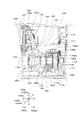
図1は、ハンマドリル100の概要を説明するための断面図である。図1に示す通り、ハンマドリル100は、使用者に把持されるハンドグリップ109を有する手持ち式の作業工具である。ハンマドリル100は、工具ビット119を当該工具ビット119の長手方向に直線状に駆動させて被加工材に対して打撃作業を行う打撃動作や、工具ビット119を当該長手方向周りに回転駆動させて被加工材に対して穴あけ作業を行う回転動作を行うために構成される。ハンマドリル100における工具ビット119の駆動形態を適宜選択するために、使用者はモードチェンジレバー(図示せず)によって工具ビット119の駆動モードを設定することができる。本実施形態に係るハンマドリル100は、工具ビット119に打撃動作および回転動作を行わせるハンマドリルモードと、工具ビット119に回転動作のみを行わせるドリルモードとを有する。このハンマドリル100が本発明に係る「作業工具」の一例であり、工具ビット119が本発明に係る「先端工具」の一例である。
(First embodiment)
FIG. 1 is a cross-sectional view for explaining the outline of the
(ハンマドリルの基本構成)
図1に示す通り、ハンマドリル100の本体ハウジング101は、ハンマドリル100の外郭を構成するギアハウジング105とモータハウジング103と、内部機構を配置するインナーハウジング130とを有する。また、本体ハウジング101は、使用者に把持されるハンドグリップ109を有する。この本体ハウジング101が本発明に係る「本体部」の一例である。
図1に示す通り、ハンドグリップ109は、駆動モータ110を通電するためのトリガ109aと、駆動モータ110に電流を供給するための電源ケーブル109bとを有する。使用者がハンドグリップ109を把持してトリガ109aを操作することにより、電源ケーブル109bを通じて駆動モータ110へと電流が供給され、工具ビット119が所定の駆動モードにより駆動される。この駆動モータ110が本発明に係る「駆動モータ」の一例である。
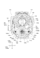
図1に示す通り、ツールホルダ159は工具ビット119を着脱自在とするために構成されとともに、本体ハウジング101に対し回転自在に配置される。このツールホルダ159が本発明に係る「ツールホルダ」の一例である。なお、図2に示す通り、ツールホルダ159には、ピストン収容領域159aと、インパクトボルト収容領域159bと、工具ビット収容領域159cとが形成されるとともに、後述する第2補償機構190が収容される。
(Basic configuration of hammer drill)
As shown in FIG. 1, the
As shown in FIG. 1, the
As shown in FIG. 1, the
図1に示す通り、駆動モータ110は出力軸部111を有する。出力軸部111は、インナーハウジング130に固定されたベアリング111aとモータハウジング103に固定されたベアリング111bとにより回動可能に支持される。出力軸部111には、当該出力軸部111と一体的に回転可能なファン112とピニオンギア113が設けられる。ファン112は出力軸部111の回転動作によって駆動モータ110への送風を行い、駆動モータ110を冷却する。なお、当該出力軸部111の回転動作は回転軸110aを規定する。この出力軸部111が本発明に係る「出力軸部」の一例であり、ピニオンギア113が本発明に係る「出力ギア」の一例であり、回転軸110aが本発明に係る「第1回転軸」の一例である。
As shown in FIG. 1, the
(工具ビット駆動機構)
次に本体ハウジング101の内部において工具ビット119を駆動する工具ビット駆動機構の構成を説明する。
図1に示す通り工具ビット駆動機構は、工具ビット119を直線状に駆動するための打撃機構120と、工具ビット119を回転駆動するための回転伝達機構150とを主体として構成される。打撃機構120と回転伝達機構150は、中間軸部116の回転動作に基づき駆動される。図2に示す通り、中間軸部116は、駆動モータ110のピニオンギア113と係合する被動ギア部材117により回転され、回転軸116cを規定する。
図3に示す通り、被動ギア部材117は、ギア歯117aと、中間軸部116に圧入される長手方向延在部117bとを有する。被動ギア部材117におけるギア歯117aが形成される領域は、ベアリング116bの外径に圧入される。なお、インナーハウジング130はピン部材115を有する。ピン部材115は、インナーハウジング130に圧入される領域と、ベアリング116bの内径に圧入される領域とを有する。
当該構成によって、図1に示す通り、中間軸部116の前側領域はギアハウジング105に配置されたベアリング116aに支持され、後側領域はベアリング116bにより支持される。
この中間軸部116が本発明に係る「回転軸部材」の一例であり、回転軸116cが本発明に係る「第2回転軸」の一例であり、被動ギア部材117が本発明に係る「被動ギア部材」の一例であり、ギア歯が本発明に係る「ギア歯」の一例であり、長手方向延在部117bが本発明に係る「長手方向延在部」の一例であり、ベアリング116aが本発明に係る「第1軸受部材」の一例であり、ベアリング116bが本発明に係る「第2軸受部材」の一例である。
(Tool bit drive mechanism)
Next, the configuration of the tool bit drive mechanism that drives the
As shown in FIG. 1, the tool bit driving mechanism is mainly composed of an
As shown in FIG. 3, the driven
With this configuration, as shown in FIG. 1, the front region of the
The
(回転伝達機構)
図2に示す通り、回転伝達機構150は、中間軸部116と一体化された第1ギア151と噛み合う第2ギア153を有する。第2ギア153は、ツールホルダ159のピストン収容領域159aと一体化されている。当該構成によって、中間軸部116の回転動作が、第1ギア151、第2ギア153およびツールホルダ159に伝達されるため、工具ビット119を回転駆動することができる。
(Rotation transmission mechanism)
As shown in FIG. 2, the
(打撃機構)
図2に示す通り、打撃機構120は、揺動機構121と、打撃要素140とを有する。この打撃機構120が本発明に係る「打撃機構」の一例であり、揺動機構121が本発明に係る「揺動機構」の一例である。
図2に示す通り揺動機構121は、回転体123と、揺動軸部125とを主体にして構成される。回転体123は、中間軸部116に対し回動自在に構成される。回転体123は、回転軸116cに対して所定の傾斜角度を有する外周面123bを有する。揺動軸部125は、回転体123の外周面123bに対し複数のスチールボール123cを介して取付けられるとともに回転体123の周囲を包囲する環状部125aと、環状部125aから上方へ突出して設けられるとともにジョイントピン126を介してピストン127と連結される軸部125bとを有する。当該構成によって、回転体123の回転に伴う外周面123bの傾斜角度の移行に環状部125aが追随することにより、軸部125bが回転軸116cに沿った前後方向にて揺動される。この軸部125bの揺動動作における直線運動成分によって、ピストン127が直線状に往復移動される。
なお、揺動機構121は、後述する第1補償機構180により付勢されるとともに、中間軸部116に対して直線状に往復移動可能に構成されている。また、揺動機構121とピストン127が連結されているため、揺動機構121の往復移動に伴いピストン127も往復移動される。
(Blow mechanism)
As shown in FIG. 2, the
As shown in FIG. 2, the
The
図2に示す通り、打撃要素140は、ツールホルダ159のピストン収容領域159aの内筒に摺動自在に配置された有底の筒状部材によるピストン127と、ピストン127の内筒に摺動自在に配置された打撃子としてのストライカ143と、ツールホルダ159の内筒に摺動自在に配置されるとともにストライカ143の運動エネルギーを工具ビット119に伝達する中間子としてのインパクトボルト145を主体として構成される。なお、ピストン127の往復移動はピストン移動軸127aを規定する。このピストン127が本発明に係る「シリンダ」の一例であり、ストライカ143が本発明に係る「打撃子」の一例であり、インパクトボルト145が本発明に係る「中間子」の一例であり、ピストン移動軸127aが本発明に係る「シリンダ移動軸」の一例である。
図2に示す通り、ピストン127の底部と、ストライカ143との間には空気室128が形成されており、ストライカ143はピストン127が往復運動することに伴う空気室128内の圧力変動により直線状に駆動される。この空気室128が本発明に係る「空気室」の一例である。
As shown in FIG. 2, the
As shown in FIG. 2, an
なお、図1に示す通り、ハンマドリル100は、ピストン移動軸127aと平行である長手方向100aと、長手方向100aと交差する方向である交差方向100bとを規定する。長手方向100aは、ピストン127が空気室128のエアを圧縮する方向である前側100a1と、当該前側100a1とは反対側の方向である後側100a2とを規定する。この長手方向100aが本発明に係る「長手方向」の一例であり、交差方向100bが本発明に係る「交差方向」の一例であり、前側100a1が本発明に係る「第1側」の一例であり、後側100a2が本発明に係る「第2側」の一例である。
なお、交差方向100bは、長手方向100aと交差する全ての方向を示す概念である。図1に示す通り、交差方向100bの内、ハンドグリップ109の延在方向成分を有するとともに長手方向100aと直交する方向を高さ方向100baと規定し、長手方向100aと高さ方向100baの双方に直交する方向を幅方向100bbと規定する。高さ方向100baにおいて、ハンドグリップ109が延在する方向を下側と規定し、当該下側とは反対の方向を上側と規定する。また、幅方向100bbにおいて、一方の方向を幅方向一方側と規定し、当該幅方向一方側とは反対の方向を幅方向他方側と規定する。
As shown in FIG. 1, the
The intersecting
なお、当該方向の定義をハンマドリル100の主要な構成に充当すると、本体ハウジング101に対し、ツールビット119は前側100a1に配置され、ハンドグリップ109は後側100a2に配置される。長手方向100aと、ピストン移動軸127aと、中間軸部116の回転軸116cと、駆動モータ110の回転軸110aはそれぞれ平行とされる。
When the definition of the direction is applied to the main configuration of the
なお、図2に示す通り、中間軸部116にはクラッチカム160がスプライン結合されている。クラッチカム160は、使用者によるモードチェンジレバーの動作に連動して前後方向へ移動される。なお、モードチェンジレバーの詳細については便宜上省略する。
モードチェンジレバーがハンマドリルモードを選択した場合は、クラッチカム160が後側100a2に移動され、クラッチカム160のクラッチ歯160aと回転体123のクラッチ歯123aが噛み合う。よってこの場合は、ツールホルダ159が回転駆動されるとともに回転体123が回転されるため、工具ビット119は打撃動作と回転動作を同時に行うことが可能となる。
一方、モードチェンジレバーがドリルモードを選択した場合は、クラッチカム160が前側100a1に移動され、クラッチ歯160aおよびクラッチ歯123aの噛み合いが解除される。よってこの場合は、ツールホルダ159が回転駆動される一方で、中間軸部116の回転が回転体123に伝達されずピストン127が駆動されないため、工具ビット119は回転動作のみを行うことが可能となる。なお、図1および図2は、ハンマドリルモードが選択された状態を示している。
As shown in FIG. 2, a
When the mode change lever selects the hammer drill mode, the
On the other hand, when the mode change lever selects the drill mode, the
(容積補償機構)
次に、図3〜図7に基づき容積補償機構170の説明を行う。容積補償機構170は、図3〜図6に示される第1補償機構180と、図7に示される第2補償機構190により構成される。この容積補償機構170が本発明に係る「容積補償機構」の一例であり、第1補償機構180が本発明に係る「第1補償機構」の一例であり、第2補償機構190が本発明に係る「第2補償機構」の一例である。
(Volume compensation mechanism)
Next, the
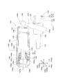
(第1補償機構)
図11に示す通り、第1補償機構180は、揺動機構121を、前側100a1に位置する揺動機構基準位置1211と、後側100a2に位置する揺動機構移動位置1212との間で往復移動可能に構成する。さらに、第1補償機構180は、揺動機構121が揺動機構移動位置1212に置かれた場合に、揺動機構121を揺動機構基準位置1211に復帰するよう構成される。この揺動機構基準位置1211が本発明に係る「揺動機構基準位置」の一例であり、揺動機構移動位置1212が本発明に係る「揺動機構移動位置」の一例である。
図3に示す通り、第1補償機構180は、揺動機構121とインナーハウジング130との間に配置されるとともに、図5に示す通り、支持部材182と第1付勢部材181を有する。この支持部材182が本発明に係る「支持部材」の一例であり、第1付勢部材181が本発明に係る「第1付勢部材」の一例である。なお、図5は図1におけるII−II線断面図である。
(First compensation mechanism)
As shown in FIG. 11, the
As shown in FIG. 3, the
図4は、図1におけるI−I線断面図である。支持部材182は、図4に示す通り、交差方向100b(高さ方向100ba、幅方向100bb)に延在するとともに、図3に示す通り、揺動機構121に当接する前側領域182aと、後側領域182bと、孔部182cを有するとともに、長手方向延在部117bに対して往復摺動可能に構成される。この前側領域182aが本発明に係る「揺動機構側領域」の一例であり、後側領域182bが本発明に係る「弾性要素側領域」の一例であり、孔部182cが本発明に係る「支持部材孔部」の一例である。図5に示す通り、第1付勢部材181は後側領域182bとインナーハウジング130との間に配置される。
4 is a cross-sectional view taken along line II in FIG. As shown in FIG. 4, the
図3に示す通り、支持部材182は板状部182dとフランジリング部182eとを有する。フランジリング部182eは板状部182dと一体化されるとともに、揺動機構121に当接されるフランジ領域と、孔部182cを形成する円筒領域とを有する。当該構成により、フランジリング部182eは揺動機構121に直接的に当接するとともに、長手方向延在部117bに対して摺動することが可能となる。このため、フランジリング部182eは、板状部182dと比して耐摩耗性を有する金属素材により構成される。なお、板状部182dにおける後側領域182bには、後述する第1付勢部材181の前側端部が当接される。
As shown in FIG. 3, the
図5に示す通り、第1付勢部材181は弾性要素181aにより構成される。弾性要素181aは、複数のコイルスプリング181bにより構成される。なお、ハンマドリル100においては2つのコイルスプリング181bにより弾性要素181aが構成されるが、使用すべきコイルスプリング181bの数はハンマドリルの構成により適宜設定することが可能である。この弾性要素181aが本発明に係る「弾性要素」の一例であり、コイルスプリング181bが本発明に係る「コイルスプリング」の一例である。
As shown in FIG. 5, the first urging
図6に示す通り、コイルスプリング181bは、インナーハウジング130の所定領域に設けられた配置領域130aに配置される。配置領域130aには、前側100a1に突出されたガイド部130bが形成されており、当該ガイド部130bの前側100a1には支持部材182が、後側100a2にはコイルスプリング181bがそれぞれ配置される。なお、ガイド部130bにおける前側100a1の先端部にはワッシャ130dを介してネジ130cが配置されており、当該ワッシャ130dにより支持部材182とコイルスプリング181bの抜け防止が図られる。この配置領域130aが本発明に係る「第1付勢部材配置領域」の一例である。ガイド部130bは、コイルスプリング181bの内径に配置されている。よって、コイルスプリング181bが圧縮された際に倒れることを防止することができる。
As shown in FIG. 6, the
また、図4に示される通り、一対のコイルスプリング181bは、交差方向100bにおいて孔部182cから等間隔となるよう当該孔部182cを挟んで配置される。このような配置形態とすることで、被動ギア部材117の周辺領域における空間を有効に活用することが可能となる。
なお、幅方向100bbにおいて、中間軸部116の回転軸116cと一対のコイルスプリング181bにおけるそれぞれの伸縮軸とは同一直線状に配置される。当該構成によって、一対のコイルスプリング181bは支持部材182を介して効率的に揺動機構121およびピストン127を前側100a1に付勢することができる。
In addition, as shown in FIG. 4, the pair of
Note that, in the width direction 100bb, the
また、図5に示す通り、幅方向100bbにおいて、中間軸部116を支持するベアリング116bの所定領域と、コイルスプリング181bの所定領域とが同一線上に位置するように配置される。当該構成によれば、中間軸部116にコイルスプリング181bを配置する必要が無くなるため、中間軸部116の延在長さを短縮化することが可能となる。
Further, as shown in FIG. 5, in the width direction 100bb, the predetermined region of the
また図5に示す通り、幅方向100bbにおいて、ギア歯117aの所定領域とコイルスプリング181bの所定領域とが同一線上に配置される。さらに、図5に示す通り、幅方向100bbにおいて、被動ギア部材117の長手方向延在部117bの所定領域とコイルスプリング181bの所定領域とが同一線上に配置される。
当該構成によれば、中間軸部116の延在長さを短縮化することができる。これを換言すると、第1補償機構180を配置するために必要な中間軸部116の長尺化を抑制することができるということができ、さらに、中間軸部116の延在長さの有効活用を図ることができるということができる。
As shown in FIG. 5, in the width direction 100bb, the predetermined region of the
According to this configuration, the extension length of the
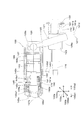
(第2補償機構)
図11に示す通り、第2補償機構190は、インパクトボルト145を前側100a1に位置するインパクトボルト基準位置1451と、後側100a2に位置するインパクトボルト移動位置1452との間で往復移動可能に構成する。なお、インパクトボルト基準位置1451は、インパクトボルト145がストライカ143に衝突される位置である。さらに、第2補償機構190は、インパクトボルト145がインパクトボルト移動位置1452に置かれた場合に、インパクトボルト145をインパクトボルト基準位置1451に復帰するよう構成される。このインパクトボルト基準位置1451が本発明に係る「中間子基準位置」の一例であり、インパクトボルト移動位置1452が本発明に係る「中間子移動位置」の一例である。
第2補償機構190は、コイルスプリング191aにより構成される第2付勢部材191と、第2付勢部材191を収容する被覆部材192とを有する。このコイルスプリング191aが本発明に係る「コイルスプリング」の一例であり、第2付勢部材191が本発明に係る「第2付勢部材」の一例であり、被覆部材192が本発明に係る「被覆部材」の一例である。
(Second compensation mechanism)
As shown in FIG. 11, the
The
図7に示す通り、第2補償機構190は、ツールホルダ159内におけるピストン収容領域159aとインパクトボルト収容領域159bとに亘り配置される。インパクトボルト145は、前側端部145aを含む大径領域145a1と、後側端部145bを含む小径領域145b1と、大径領域145a1と小径領域145b1の境界に形成される段差領域145cとを有する。この前側端部145aが本発明に係る「第1端部」の一例であり、大径領域145a1が本発明に係る「第1領域」の一例であり、後側端部145bが本発明に係る「第2端部」の一例であり、小径領域145b1が本発明に係る「第2領域」の一例であり、段差領域145cが本発明に係る「中間領域」の一例である。
As shown in FIG. 7, the
図7に示す通り、被覆部材192は、長手方向100aに延在する長手方向壁部192aと、交差方向100bに延在する交差方向壁部192bと、交差方向壁部192bに設けられる孔部192cとを有する。この長手方向壁部192aが本発明に係る「長手方向壁部」の一例であり、交差方向壁部192bが本発明に係る「交差方向壁部」の一例であり、孔部192cが本発明に係る「被覆部材孔部」の一例である。当該構成により、被覆部材192は、インパクトボルト145の大径領域145a1と、段差領域145cと、少なくとも一部の小径領域145b1とを被覆する。なお、被覆部材192に被覆されない小径領域145b1は、孔部192cから後側100a2へ延出される。
As shown in FIG. 7, the covering
図7に示す通り、コイルスプリング191aは、交差方向壁部192bと段差領域145cとの間に配置され、段差領域145cを付勢する。なお、コイルスプリング191aの前側端部と段差領域145cとの間には、直線状に往復移動可能に構成されたリング状部材192dが介在される。当該構成によって、第2補償機構190はインパクトボルト145を前側100a1に付勢することが可能となる。
As shown in FIG. 7, the
(容積補償機構の動作)
次に、図8〜図11に基づき容積補償機構170の動作につき説明する。容積補償機構170は、工具ビット119が直線状の駆動動作を行う場合に機能を発現する。すなわち、図8〜図11は、ハンマドリル100がハンマドリルモードに設定されている場合の動作を示す。なお、ハンマドリル100においては、使用者が工具ビット119を加工対象に押し付けて使用される。よって、インパクトボルト145は工具ビット119に押され後側100a2に移動される。この状態のインパクトボルト145の位置が、インパクトボルト基準位置1451を規定する。
(Operation of volume compensation mechanism)
Next, the operation of the
図8は、揺動軸部125の軸部125bが後側100a2に移動している状態を示す。当該状態においては、揺動機構121は揺動機構基準位置1211に置かれ、インパクトボルト145はインパクトボルト基準位置1451に置かれる。中間軸部116の回転に伴い、軸部125bは前側100a1に移動される。図9は、軸部125bの移動に伴いピストン127が前側100a1に移動され、空気室128のエアが最大圧縮を迎えた状態を示す。
FIG. 8 shows a state where the
図10に示す通り、空気室128のエアが最大圧縮を迎えた反力により、ピストン127が後側100a2に移動される。当該ピストン127の移動に伴い、コイルスプリング181bが圧縮され、揺動機構121が揺動機構基準位置1211から揺動機構移動位置1212に移動される。これによって、第1補償機構180は、当該反力を緩衝することにより振動抑制を図る。
As shown in FIG. 10, the
なお、揺動機構121が搖動機構基準位置1211から搖動機構移動位置1212に移動されることに伴い、ピストン127が前側100a1から後側100a2に移動することによって空気室128の容積が拡大される。当該空気室128の容積拡大は、ピストン127を円滑に駆動するための空気穴(図示せず)から、空気室128へエアが流入することを主要因とするものである。
当該状態に引き続き、軸部125bはさらに前側100a1へ揺動する。なお、揺動機構移動位置1212に置かれた揺動機構121は、コイルスプリング181bに付勢されて揺動機構基準位置1211へ移動される。当該揺動機構121の移動に伴い、ピストン127が前側100a1に移動される。
As the
Following this state, the
図11は、空気室128のエアの膨張によりストライカ143がインパクトボルト145に衝突し、工具ビット119が直線状に駆動された直後の状態を示す。工具ビット119が被加工対象に衝突した際の反力が工具ビット119を経由してインパクトボルト145に伝達されることにより、インパクトボルト145は、インパクトボルト基準位置1451からインパクトボルト移動位置1452へ移動される。そしてインパクトボルト移動位置1452に移動されたインパクトボルト145がストライカ143に衝突し、ストライカ143が後側100a2に移動される。当該動作によって空気室128の容積が補償される。なお、インパクトボルト移動位置1452に置かれたインパクトボルト145は、コイルスプリング191aに付勢されてインパクトボルト基準位置1451へ移動される。
なお、長手方向100aにおける揺動機構基準位置1211と揺動機構移動位置1212の間の距離と、長手方向100aにおけるインパクトボルト基準位置1451とインパクトボルト移動位置1452の間の距離は同一とされる。
FIG. 11 shows a state immediately after the
The distance between the swing
図8〜図11にて説明したサイクルを繰り返すことにより、ハンマドリル100は、第1補償機構180により振動抑制機能を発現するとともに、第1補償機構180の動作により生ずる空気室128の容積の変化を第2補償機構190により補償しながら加工作業を遂行することが可能となる。すなわち、上述した構成により、振動抑制とストライカ143の不安定駆動要素の低減化が図られたハンマドリル100を得ることが可能となる。
By repeating the cycle described with reference to FIGS. 8 to 11, the
(第2実施形態)
次に、図12および図13に基づき、本発明の第2実施形態に係るハンマドリル200の説明を行う。第2実施形態のハンマドリル200は、第1実施形態のハンマドリル100と比して主に駆動モータ110と中間軸部116の配置形態と、第1補償機構180の構成が異なる。なお、ハンマドリル200の説明において、ハンマドリル100と同等の機能を奏する構成および部品については、同一の図面番号を付してその説明を省略する。このハンマドリル200が本発明に係る「作業工具」の一例である。
(Second Embodiment)
Next, a
図12に示す通りハンマドリル200においては、本体ハウジング101に対し、駆動モータ110の回転軸110aと中間軸部116の回転軸116cとが交差するよう配置されている。当該配置形態に係る駆動モータ110の回転動作を中間軸部116に伝達するため、被動ギア部材118はべべルギア118aにより構成される。この被動ギア部材118が本発明に係る「被動ギア部材」の一例であり、べべルギア118aが本発明に係る「べべルギア」の一例である。
なお、ハンドグリップ109は環状に形成されるとともに、ハンドグリップ109の下側にはバッテリ109dを装着するためのバッテリ装着部109cが設けられる。
As shown in FIG. 12, the
The
図13に示す通り、べべルギア118aは、交差方向延在部118bと、当該交差方向延在部118bに設けられたギア歯118cを有する。第1補償機構180は、揺動機構121の後側100a2に直線状に移動可能に配置されたリング状部材183と、当該リング状部材183と交差方向延在部118bとの間に配置された第1付勢部材181とを有する。第1付勢部材181を構成する弾性要素181aとして、コニカルスプリング181cが使用される。コニカルスプリング181cの大径部181dは交差方向延在部118bに当接され、小径部181eはリング状部材183に当接される。この交差方向延在部118bが本発明に係る「交差方向延在部」の一例であり、コニカルスプリング181cが本発明に係る「コニカルスプリング」の一例であり、大径部181dが本発明に係る「大径部」の一例であり、小径部181eが本発明に係る「小径部」の一例である。
As shown in FIG. 13, the
ハンマドリル200の容積補償機構170は、上述した構成を有する第1補償機構180と、第2補償機構190とにより、ハンマドリル100の容積補償機構170と同等の動作を行うことができる。よって、振動抑制とストライカ143の不安定駆動要素の低減化が図られたハンマドリル200を得ることが可能となる。
The
なお、本発明に係る作業工具は、上述した構成に限られるものではない。例えば、駆動モータ110と中間軸部116の配置形態や、被動ギア部材の構成については、他の構成を採用することが可能である。さらに、他の構成を付加することも可能である。
The work tool according to the present invention is not limited to the configuration described above. For example, other configurations can be adopted for the arrangement of the
以上の発明の趣旨に鑑み、本発明に係る作業工具は、下記の態様が構成可能である。なお、各態様は、単独で、あるいは互いに組み合わされて用いられるだけでなく、請求項に記載された発明と組み合わされて用いられる。
(態様1)
前記支持部材は、板状部と、板状部と一体化されるフランジリング部とを有し、
前記フランジリング部は前記板状部と比して耐摩耗性を有するとともに、前記揺動機構に直接的に当接する領域と、前記支持部材孔部を形成する領域とを有することを特徴とする。
(態様2)
前記第1付勢部材配置領域は、前記第2側から前記第1側に突出するガイド部を有し、前記支持部材と前記弾性要素は、前記ガイド部に配置されることを特徴とする。
(態様3)
前記交差方向において、前記中間軸部の前記回転軸と複数の前記コイルスプリングにおけるそれぞれの伸縮軸とは同一直線状に配置されることを特徴とする。
(態様4)
前記長手方向における前記揺動機構基準位置と前記揺動機構移動位置の間の距離と、前記長手方向における前記中間子基準位置と前記中間子移動位置の間の距離は同一に構成されることを特徴とする。
In view of the gist of the above invention, the working tool according to the present invention can be configured in the following manner. Each aspect is used not only alone or in combination with each other, but also in combination with the invention described in the claims.
(Aspect 1)
The support member has a plate-like portion and a flange ring portion integrated with the plate-like portion,
The flange ring portion has wear resistance as compared with the plate-like portion, and has a region that directly contacts the swinging mechanism and a region that forms the support member hole. .
(Aspect 2)
The first urging member arrangement region has a guide part protruding from the second side to the first side, and the support member and the elastic element are arranged in the guide part.
(Aspect 3)
In the crossing direction, the rotation shaft of the intermediate shaft portion and each of the telescopic shafts of the plurality of coil springs are arranged in the same straight line.
(Aspect 4)
The distance between the swing mechanism reference position in the longitudinal direction and the swing mechanism moving position and the distance between the meson reference position and the meson moving position in the longitudinal direction are configured to be the same. To do.
(本実施形態の各構成要素と本発明の各構成要素の対応関係)
本実施形態の各構成要素と本発明の各構成要素の対応関係を以下の通りである。なお、本実施形態は、本発明を実施するための形態の一例を示すものであり、本発明は、本実施形態の構成に限定されるものではない。
ハンマドリル100またはハンマドリル200は本発明に係る「作業工具」の一例である。工具ビット119は本発明に係る「先端工具」の一例である。本体ハウジング101は本発明に係る「本体部」の一例である。駆動モータ110は本発明に係る「駆動モータ」の一例である。出力軸部111は本発明に係る「出力軸部」の一例である。ピニオンギア113は本発明に係る「出力ギア」の一例である。回転軸110aは本発明に係る「第1回転軸」の一例である。中間軸部116は本発明に係る「回転軸部材」の一例である。回転軸116cは本発明に係る「第2回転軸」の一例である。被動ギア部材117または被動ギア部材118は本発明に係る「被動ギア部材」の一例である。ギア歯117aは本発明に係る「ギア歯」の一例である。長手方向延在部117bは本発明に係る「長手方向延在部」の一例である。ベアリング116aは本発明に係る「第1軸受部材」の一例である。ベアリング116bは本発明に係る「第2軸受部材」の一例である。打撃機構120は本発明に係る「打撃機構」の一例である。揺動機構121は本発明に係る「揺動機構」の一例である。ピストン127は本発明に係る「シリンダ」の一例である。ストライカ143は本発明に係る「打撃子」の一例である。インパクトボルト145は本発明に係る「中間子」の一例である。空気室128は本発明に係る「空気室」の一例である。ピストン移動軸127aは本発明に係る「シリンダ移動軸」の一例である。長手方向100aは本発明に係る「長手方向」の一例である。交差方向100bは本発明に係る「交差方向」の一例である。前側100a1は本発明に係る「第1側」の一例である。後側100a2は本発明に係る「第2側」の一例である。容積補償機構170は本発明に係る「容積補償機構」の一例である。第1補償機構180は本発明に係る「第1補償機構」の一例である。第2補償機構190は本発明に係る「第2補償機構」の一例である。揺動機構基準位置1211は本発明に係る「揺動機構基準位置」の一例である。揺動機構移動位置1212は本発明に係る「揺動機構移動位置」の一例である。支持部材182は本発明に係る「支持部材」の一例である。第1付勢部材181は本発明に係る「第1付勢部材」の一例である。前側領域182aは本発明に係る「揺動機構側領域」の一例である。後側領域182bは本発明に係る「弾性要素側領域」の一例である。孔部182cは本発明に係る「支持部材孔部」の一例である。弾性要素181aは本発明に係る「弾性要素」の一例である。コイルスプリング181bは本発明に係る「コイルスプリング」の一例である。配置領域130aは本発明に係る「第1付勢部材配置領域」の一例である。インパクトボルト基準位置1451は本発明に係る「中間子基準位置」の一例である。インパクトボルト移動位置1452は本発明に係る「中間子移動位置」の一例である。コイルスプリング191aは本発明に係る「コイルスプリング」の一例である。第2付勢部材191は本発明に係る「第2付勢部材」の一例である。被覆部材192は本発明に係る「被覆部材」の一例である。前側端部145aは本発明に係る「第1端部」の一例である。大径領域145a1は本発明に係る「第1領域」の一例である。後側端部145bは本発明に係る「第2端部」の一例である。小径領域145b1は本発明に係る「第2領域」の一例である。段差領域145cは本発明に係る「中間領域」の一例である。長手方向壁部192aは本発明に係る「長手方向壁部」の一例である。交差方向壁部192bは本発明に係る「交差方向壁部」の一例である。孔部192cは本発明に係る「被覆部材孔部」の一例である。べべルギア118aは本発明に係る「べべルギア」の一例である。交差方向延在部118bは本発明に係る「交差方向延在部」の一例である。コニカルスプリング181cは本発明に係る「コニカルスプリング」の一例である。大径部181dは本発明に係る「大径部」の一例である。小径部181eは本発明に係る「小径部」の一例である。
(Correspondence between each component of this embodiment and each component of the present invention)
The correspondence between each component of the present embodiment and each component of the present invention is as follows. In addition, this embodiment shows an example of the form for implementing this invention, and this invention is not limited to the structure of this embodiment.
The
100、200 ハンマドリル(作業工具)
100a 長手方向
100a1 前側(第1側)
100a2 後側(第2側)
100b 交差方向
100ba 高さ方向
100bb 幅方向(交差方向)
101 本体ハウジング(本体部)
103 モータハウジング
105 ギアハウジング
109 ハンドグリップ
109a トリガ
109b 電源ケーブル
109c バッテリ装着部
109d バッテリ
110 駆動モータ
110a 回転軸(第1回転軸)
111 出力軸部
111a ベアリング
111b ベアリング
112 ファン
113 ピニオンギア(出力ギア)
115 ピン部材
116 中間軸部(回転軸部材)
116a ベアリング(第1軸受部材)
116b ベアリング(第2軸受部材)
116c 回転軸
117 被動ギア部材
117a ギア歯
117b 長手方向延在部
118 被動ギア部材
118a べべルギア
118b 交差方向延在部
118c ギア歯
119 工具ビット(先端工具)
120 打撃機構
121 揺動機構
1211 揺動機構基準位置
1212 揺動機構移動位置
123 回転体
123a クラッチ歯
123b 外周面
123c スチールボール
125 揺動軸部
125a 環状部
125b 軸部
126 ジョイントピン
127 ピストン(シリンダ)
127a ピストン移動軸(シリンダ移動軸)
128 空気室
130 インナーハウジング
130a 配置領域(第1付勢部材配置領域)
130b ガイド部
130c ネジ
130d ワッシャ
140 打撃要素
143 ストライカ(打撃子)
145 インパクトボルト(中間子)
145a 前側端部(第1端部)
145a1 大径領域(第1領域)
145b 後側端部(第2端部)
145b1 小径領域(第2領域)
145c 段差領域(中間領域)
1451 インバクトボルト基準位置
1452 インパクトボルト移動位置
150 回転伝達機構
151 第1ギア
153 第2ギア
159 ツールホルダ
159a ピストン収容領域
159b インパクトボルト収容領域
159c 工具ビット収容領域
160 クラッチカム
160a クラッチ歯
170 容積補償機構
180 第1補償機構
181 第1付勢部材
181a 弾性要素
181b コイルスプリング
181c コニカルスプリング
181d 大径部
181e 小径部
182 支持部材
182a 前側領域(揺動機構側領域)
182b 後側領域(弾性要素側領域)
182c 孔部(支持部材孔部)
182d 板状部
182e フランジリング部
183 リング状部材
190 第2補償機構
191 第2付勢部材
191a コイルスプリング
192 被覆部材
192a 長手方向壁部
192b 交差方向壁部
192c 孔部(被覆部材孔部)
192d リング状部材
100, 200 Hammer drill (work tool)
100a Longitudinal direction 100a1 Front side (first side)
100a2 Rear side (second side)
100b Cross direction 100ba Height direction 100bb Width direction (cross direction)
101 Main body housing (main body)
103
111
115
116a Bearing (first bearing member)
116b Bearing (second bearing member)
116c Rotating
120
127a Piston movement axis (cylinder movement axis)
145 Impact bolt (meson)
145a Front end (first end)
145a1 Large-diameter region (first region)
145b Rear end (second end)
145b1 small diameter region (second region)
145c Stepped region (intermediate region)
1451 Invert
182b Rear region (elastic element side region)
182c hole (support member hole)
182d Plate-shaped
192d Ring-shaped member
Claims (8)
本体部を有し、
前記本体部は、
前記先端工具を保持するツールホルダと、
駆動モータと、
前記駆動モータにより回転駆動される回転軸部材と、
前記回転軸部材の回転動作に基づき前記先端工具を直線状に駆動する打撃機構と、を収容し、
前記打撃機構は、
直線状に往復移動可能に構成されたシリンダと、
前記シリンダに収容されるとともに前記シリンダ内において直線状に往復移動可能に構成された打撃子と、
前記打撃子と前記シリンダで形成される空気室と、
前記シリンダに連結されるとともに、前記回転軸部材の回転動作に基づく揺動動作により、前記シリンダを往復移動させる揺動機構と、
前記ツールホルダに収容されるとともに直線状に往復移動可能に構成された中間子と、を有し、
前記シリンダの往復移動により生ずる前記空気室内の圧力変動を介して前記打撃子を前記中間子に衝突させ、さらに前記中間子を前記先端工具に衝突させることにより前記先端工具を直線状に移動するよう構成され、
前記作業工具はさらに、
シリンダ移動軸と平行である長手方向と、前記長手方向と交差する方向である交差方向とを規定し、
前記長手方向は、前記シリンダが空気室のエアを圧縮する方向である第1側と、前記第1側とは反対側の方向である第2側とを規定し、
前記本体部はさらに、前記空気室の容積を補償する容積補償機構を収容し、
前記容積補償機構は、第1補償機構と、第2補償機構とを有し、
前記第1補償機構は、前記揺動機構を、前記第1側に位置する揺動機構基準位置と、前記第2側に位置する揺動機構移動位置との間で往復移動可能に構成するとともに、前記揺動機構が前記揺動機構移動位置に置かれた場合に、前記揺動機構を前記揺動機構基準位置に置くよう前記揺動機構を付勢する第1付勢部材を有し、
前記第2補償機構は、前記中間子を、前記第1側に位置する中間子基準位置と、前記第2側に位置する中間子移動位置との間で往復移動可能に構成するとともに、前記中間子が前記中間子移動位置に置かれた場合に、前記中間子を前記中間子基準位置に置くよう前記中間子を付勢する第2付勢部材を有し、
前記容積補償機構は、さらに、
前記第1補償機構が、前記シリンダの前記第2側から前記第1側への移動動作に伴う反力により前記揺動機構を前記揺動機構基準位置から前記揺動機構移動位置へ移動し、当該揺動機構の移動動作に基づき前記シリンダを前記第2側へ移動することによって前記空気室の容積を拡大するとともに、
前記第1補償機構が前記空気室の容積を拡大した状態において、前記第2補償機構が、前記先端工具による前記所定の加工作業の反力により前記中間子を前記中間子基準位置から前記中間子移動位置へ移動し、当該中間子の移動動作に基づき前記打撃子を前記第2側に移動することによって前記空気室の容積を補償するよう構成されており、
前記長手方向において、前記揺動機構基準位置と前記揺動機構移動位置の間の距離と、前記中間子基準位置と前記中間子移動位置の間の距離は同一となるよう構成されることを特徴とする作業工具。 A work tool that performs a predetermined machining operation on a workpiece by moving the tip tool linearly,
Having a body part,
The main body is
A tool holder for holding the tip tool;
A drive motor;
A rotating shaft member that is rotationally driven by the drive motor;
A striking mechanism that linearly drives the tip tool based on the rotational movement of the rotating shaft member;
The striking mechanism is
A cylinder configured to be capable of reciprocating linearly;
A striker that is housed in the cylinder and configured to reciprocate linearly in the cylinder;
An air chamber formed by the striker and the cylinder;
A swing mechanism coupled to the cylinder and reciprocatingly moving the cylinder by a swing operation based on a rotation operation of the rotary shaft member;
An intermediate element housed in the tool holder and configured to be linearly reciprocable;
The impact tool is made to collide with the intermediate element through pressure fluctuations in the air chamber caused by the reciprocating movement of the cylinder, and the intermediate tool is made to collide with the distal tool to move the distal tool linearly. ,
The work tool further includes:
Defining a longitudinal direction parallel to the cylinder movement axis and an intersecting direction that intersects the longitudinal direction;
The longitudinal direction defines a first side that is a direction in which the cylinder compresses air in an air chamber, and a second side that is a direction opposite to the first side,
The main body further contains a volume compensation mechanism for compensating the volume of the air chamber,
The volume compensation mechanism has a first compensation mechanism and a second compensation mechanism,
The first compensation mechanism is configured to reciprocate the swing mechanism between a swing mechanism reference position located on the first side and a swing mechanism moving position located on the second side. A first urging member that urges the swing mechanism to place the swing mechanism at the swing mechanism reference position when the swing mechanism is placed at the swing mechanism moving position;
The second compensation mechanism is configured to reciprocate the meson between an meson reference position located on the first side and an meson move position located on the second side, and the meson is configured to be the meson A second urging member that urges the meson to place the meson at the meson reference position when placed in the moving position;
The volume compensation mechanism further includes:
The first compensation mechanism moves the rocking mechanism from the rocking mechanism reference position to the rocking mechanism moving position by a reaction force accompanying a movement operation of the cylinder from the second side to the first side; While expanding the volume of the air chamber by moving the cylinder to the second side based on the movement operation of the swing mechanism,
In a state where the first compensation mechanism expands the volume of the air chamber, the second compensation mechanism moves the meson from the meson reference position to the meson movement position by a reaction force of the predetermined machining operation by the tip tool. Moving, and configured to compensate the volume of the air chamber by moving the striker to the second side based on the moving operation of the meson ,
In the longitudinal direction, the distance between the swing mechanism reference position and the swing mechanism moving position and the distance between the meson reference position and the meson moving position are configured to be the same. Work tools.
前記回転軸部材は、前記長手方向に延在され、
前記本体部は、前記回転軸部材の前記第1側の所定領域を支持する第1軸受部材と、前記回転軸部材の前記第2側の所定領域を支持する第2軸受部材と、前記第1付勢部材の一方の端部が配置される第1付勢部材配置領域を有し、
前記交差方向において、前記第2軸受部材の所定領域と前記第1付勢部材の所定領域とが同一線上に位置するように配置されることを特徴とする作業工具。 The work tool according to claim 1,
The rotating shaft member extends in the longitudinal direction,
The main body includes a first bearing member that supports a predetermined region on the first side of the rotating shaft member, a second bearing member that supports a predetermined region on the second side of the rotating shaft member, and the first A first biasing member placement region in which one end of the biasing member is placed;
The work tool, wherein the predetermined area of the second bearing member and the predetermined area of the first biasing member are arranged on the same line in the crossing direction.
前記駆動モータは、出力ギアを備える出力軸部を有し、
前記回転軸部材は、前記出力ギアと係合するギア歯を備える被動ギア部材を有し、
前記交差方向において、前記ギア歯の所定領域と前記第1付勢部材の所定領域とが同一線上に位置するように配置されることを特徴とする作業工具。 The work tool according to claim 1 or 2,
The drive motor has an output shaft portion including an output gear,
The rotating shaft member has a driven gear member having gear teeth that engage with the output gear,
The work tool, wherein the predetermined region of the gear teeth and the predetermined region of the first biasing member are disposed on the same line in the crossing direction.
前記駆動モータは、出力ギアを備える出力軸部を有し、
前記回転軸部材は、前記出力ギアと係合するギア歯を備える被動ギア部材を有し、
前記被動ギア部材は、前記長手方向に延在するとともに前記回転軸部材に圧入される長手方向延在部を有し、
前記第1付勢部材は、前記交差方向に延在する支持部材と、前記支持部材と前記第1付勢部材配置領域との間に配置されるとともに、前記支持部材を前記第2側から前記第1側へ付勢する弾性要素と、を有し、
前記支持部材は、前記揺動機構に当接する揺動機構側領域と、前記弾性要素と当接する弾性要素側領域と、前記長手方向延在部を貫通する支持部材孔部を有するとともに、前記長手方向延在部に対して往復摺動可能に構成され、
前記交差方向において、前記長手方向延在部の所定領域と前記弾性要素の所定領域とは同一線上に位置するように配置されることを特徴とする作業工具。 A work tool according to claim 2 ,
The drive motor has an output shaft portion including an output gear,
The rotating shaft member has a driven gear member having gear teeth that engage with the output gear,
The driven gear member has a longitudinally extending portion that extends in the longitudinal direction and is press-fitted into the rotating shaft member;
The first urging member is disposed between the support member extending in the intersecting direction, the support member and the first urging member arrangement region, and the support member is disposed from the second side. An elastic element biased toward the first side,
The support member has a swing mechanism side region that contacts the swing mechanism, an elastic element side region that contacts the elastic element, a support member hole that penetrates the longitudinally extending portion, and the longitudinal direction. It is configured to be slidable back and forth with respect to the direction extension part,
In the crossing direction, the predetermined area of the longitudinally extending portion and the predetermined area of the elastic element are arranged so as to be located on the same line.
前記弾性要素は、複数のコイルスプリングにより構成され、
複数の前記コイルスプリングは、前記交差方向において前記支持部材孔部から等間隔となるよう前記支持部材孔部を挟んで配置されることを特徴とする作業工具。 The work tool according to claim 4 ,
The elastic element is composed of a plurality of coil springs,
The work tool, wherein the plurality of coil springs are arranged across the support member hole so as to be equidistant from the support member hole in the intersecting direction.
前記駆動モータは、出力ギアを備える出力軸部と、前記出力軸部の回転動作により規定される第1回転軸と、を有し、
前記回転軸部材は、前記出力ギアと係合する被動ギア部材と、前記回転軸部材の回転動作により規定される第2回転軸と、を有し、
前記被動ギア部材は、べべルギアにより構成されるとともに前記交差方向に延在された交差方向延在部を有し、
前記駆動モータと前記回転軸部材は、前記第1回転軸と前記第2回転軸が交差するよう配置され、
前記第1付勢部材は、前記交差方向延在部と前記揺動機構との間に配置された弾性要素により構成されることを特徴とする作業工具。 The work tool according to claim 1,
The drive motor has an output shaft portion including an output gear, and a first rotation shaft defined by a rotation operation of the output shaft portion,
The rotating shaft member includes a driven gear member that engages with the output gear, and a second rotating shaft that is defined by a rotating operation of the rotating shaft member,
The driven gear member includes a bevel gear and has a cross direction extending portion that extends in the cross direction;
The drive motor and the rotating shaft member are arranged such that the first rotating shaft and the second rotating shaft intersect,
The first urging member is constituted by an elastic element disposed between the intersecting direction extending portion and the swing mechanism.
前記弾性要素は、大径部と小径部とを有するコニカルスプリングにより構成され、
前記大径部は前記交差方向延在部に向かって配置され、前記小径部は前記揺動機構に向かって配置されることを特徴とする作業工具。 The work tool according to claim 6,
The elastic element is constituted by a conical spring having a large diameter portion and a small diameter portion,
The work tool characterized in that the large-diameter portion is disposed toward the intersecting direction extending portion, and the small-diameter portion is disposed toward the swing mechanism.
前記中間子は、前記第1側の第1端部を含む第1領域と、前記第2側の第2端部を含む第2領域と、前記第1領域と前記第2領域の境界に形成される中間領域と、を有し、
前記第2補償機構は、前記第1領域と、前記中間領域と、少なくとも一部の前記第2領域を被覆する被覆部材と、を有し、
前記被覆部材は、前記長手方向に延在する長手方向壁部と、前記交差方向に延在する交差方向壁部と、前記交差方向壁部に設けられるとともに前記第2領域が挿通される被覆部材孔部と、を有し、
前記第2付勢部材は、前記交差方向壁部と前記中間領域の所定領域との間に配置されるコイルスプリングにより構成されることを特徴とする作業工具。
The work tool according to any one of claims 1 to 7,
The meson is formed at a first region including the first end on the first side, a second region including the second end on the second side, and a boundary between the first region and the second region. An intermediate region,
The second compensation mechanism has the first region, the intermediate region, and a covering member that covers at least a part of the second region,
The covering member is provided in the longitudinal direction wall portion extending in the longitudinal direction, the intersecting direction wall portion extending in the intersecting direction, and the intersecting direction wall portion, and the covering member through which the second region is inserted. A hole, and
The work tool characterized in that the second urging member is constituted by a coil spring disposed between the intersecting direction wall portion and a predetermined region of the intermediate region.
Priority Applications (4)
| Application Number | Priority Date | Filing Date | Title |
|---|---|---|---|
| JP2015101949A JP6479570B2 (en) | 2015-05-19 | 2015-05-19 | Work tools |
| CN201610245370.0A CN106166729B (en) | 2015-05-19 | 2016-04-19 | work tool |
| EP16170175.0A EP3132897B1 (en) | 2015-05-19 | 2016-05-18 | Power tool |
| US15/157,700 US10500706B2 (en) | 2015-05-19 | 2016-05-18 | Power tool |
Applications Claiming Priority (1)
| Application Number | Priority Date | Filing Date | Title |
|---|---|---|---|
| JP2015101949A JP6479570B2 (en) | 2015-05-19 | 2015-05-19 | Work tools |
Publications (2)
| Publication Number | Publication Date |
|---|---|
| JP2016215309A JP2016215309A (en) | 2016-12-22 |
| JP6479570B2 true JP6479570B2 (en) | 2019-03-06 |
Family
ID=56137079
Family Applications (1)
| Application Number | Title | Priority Date | Filing Date |
|---|---|---|---|
| JP2015101949A Active JP6479570B2 (en) | 2015-05-19 | 2015-05-19 | Work tools |
Country Status (4)
| Country | Link |
|---|---|
| US (1) | US10500706B2 (en) |
| EP (1) | EP3132897B1 (en) |
| JP (1) | JP6479570B2 (en) |
| CN (1) | CN106166729B (en) |
Families Citing this family (12)
| Publication number | Priority date | Publication date | Assignee | Title |
|---|---|---|---|---|
| JP6325360B2 (en) * | 2014-06-12 | 2018-05-16 | 株式会社マキタ | Impact tool |
| US11052525B2 (en) * | 2016-03-03 | 2021-07-06 | Makita Corporation | Hammer drill |
| JP6709120B2 (en) | 2016-07-15 | 2020-06-10 | 株式会社マキタ | Hammer tool |
| US20190136063A1 (en) * | 2017-11-09 | 2019-05-09 | Vinventions Usa, Llc | Particulate material for use in the production of a cork composite material or an article of manufacture comprising cork |
| GB201812437D0 (en) | 2018-07-31 | 2018-09-12 | Black & Decker Inc | Hammer drill |
| JP7193412B2 (en) * | 2019-04-22 | 2022-12-20 | 株式会社マキタ | Work tools |
| DE102020127505A1 (en) * | 2019-10-21 | 2021-04-22 | Makita Corporation | DRILL |
| WO2022216964A1 (en) | 2021-04-07 | 2022-10-13 | Milwaukee Electric Tool Corporation | Impact power tool |
| JP7825526B2 (en) * | 2022-07-06 | 2026-03-06 | 株式会社マキタ | Hammer drill |
| CN116652270B (en) * | 2022-09-08 | 2026-02-06 | 玉环图远机电有限公司 | Power head for slot or gear shaping |
| CN115870930A (en) * | 2022-12-19 | 2023-03-31 | 浙江马特工具有限公司 | Electric tool |
| JP2025110164A (en) * | 2024-01-15 | 2025-07-28 | 株式会社マキタ | Impact tool |
Family Cites Families (28)
| Publication number | Priority date | Publication date | Assignee | Title |
|---|---|---|---|---|
| JPS54165502U (en) * | 1978-05-09 | 1979-11-20 | ||
| US4325436A (en) * | 1980-05-21 | 1982-04-20 | Hilti Aktiengesellschaft | Hammer drill or chipping hammer device |
| DE3039669A1 (en) * | 1980-10-21 | 1982-05-27 | Robert Bosch Gmbh, 7000 Stuttgart | DRILLING HAMMER |
| DE3506695A1 (en) * | 1985-02-26 | 1986-08-28 | Robert Bosch Gmbh, 7000 Stuttgart | DRILLING HAMMER |
| DE3807078A1 (en) * | 1988-03-04 | 1989-09-14 | Black & Decker Inc | DRILLING HAMMER |
| DE4135240A1 (en) * | 1991-10-25 | 1993-04-29 | Bosch Gmbh Robert | DRILLING HAMMER |
| DE4239294A1 (en) * | 1992-11-23 | 1994-05-26 | Black & Decker Inc | Hammer drill with pneumatic hammer mechanism |
| JP3424880B2 (en) * | 1995-08-18 | 2003-07-07 | 株式会社マキタ | Hammer drill |
| US5954140A (en) * | 1997-06-18 | 1999-09-21 | Milwaukee Electric Tool Corporation | Rotary hammer with improved pneumatic drive system |
| GB0213289D0 (en) * | 2002-06-11 | 2002-07-24 | Black & Decker Inc | Rotary hammer |
| DE102004058686A1 (en) * | 2004-09-03 | 2006-03-09 | Robert Bosch Gmbh | Power tool with a drive that can be switched over between the operating modes drilling, impact drilling, and chiseling |
| JP4815119B2 (en) * | 2004-10-15 | 2011-11-16 | 株式会社マキタ | Reciprocating work tool |
| JP4593387B2 (en) * | 2005-07-04 | 2010-12-08 | 株式会社マキタ | Electric tool |
| GB2435442A (en) * | 2006-02-24 | 2007-08-29 | Black & Decker Inc | Powered hammer with helically shaped vent channel |
| US20100038104A1 (en) * | 2006-07-10 | 2010-02-18 | Otto Baumann | Hand held machine tool |
| DE102006056849A1 (en) * | 2006-12-01 | 2008-06-05 | Robert Bosch Gmbh | Hand tool |
| DE102006060320A1 (en) * | 2006-12-20 | 2008-06-26 | Robert Bosch Gmbh | Schlagwerk for a hand tool |
| JP5100171B2 (en) * | 2007-03-27 | 2012-12-19 | 株式会社マキタ | Impact type work tool |
| US8485274B2 (en) | 2007-05-14 | 2013-07-16 | Makita Corporation | Impact tool |
| JP4965334B2 (en) * | 2007-05-14 | 2012-07-04 | 株式会社マキタ | Impact tool |
| JP5058726B2 (en) * | 2007-09-06 | 2012-10-24 | 株式会社マキタ | Impact tool |
| DE102008010100A1 (en) * | 2008-02-20 | 2009-08-27 | Robert Bosch Gmbh | Hand tool |
| JP5345893B2 (en) * | 2009-05-08 | 2013-11-20 | 株式会社マキタ | Impact tool |
| JP5456555B2 (en) * | 2010-04-23 | 2014-04-02 | 株式会社マキタ | Electric tool |
| JP5518617B2 (en) * | 2010-08-02 | 2014-06-11 | 株式会社マキタ | Impact tool |
| JP5635945B2 (en) * | 2011-05-24 | 2014-12-03 | 株式会社マキタ | Electric tool |
| DE102012209875A1 (en) * | 2012-06-13 | 2013-12-19 | Robert Bosch Gmbh | striking mechanism |
| JP2015047661A (en) * | 2013-08-30 | 2015-03-16 | 日立工機株式会社 | Impact tool |
-
2015
- 2015-05-19 JP JP2015101949A patent/JP6479570B2/en active Active
-
2016
- 2016-04-19 CN CN201610245370.0A patent/CN106166729B/en active Active
- 2016-05-18 US US15/157,700 patent/US10500706B2/en active Active
- 2016-05-18 EP EP16170175.0A patent/EP3132897B1/en active Active
Also Published As
| Publication number | Publication date |
|---|---|
| US10500706B2 (en) | 2019-12-10 |
| EP3132897A1 (en) | 2017-02-22 |
| JP2016215309A (en) | 2016-12-22 |
| CN106166729A (en) | 2016-11-30 |
| US20160339577A1 (en) | 2016-11-24 |
| EP3132897B1 (en) | 2020-07-15 |
| CN106166729B (en) | 2020-10-16 |
Similar Documents
| Publication | Publication Date | Title |
|---|---|---|
| JP6479570B2 (en) | Work tools | |
| JP6309881B2 (en) | Work tools | |
| JP6096593B2 (en) | Reciprocating work tool | |
| JP6325360B2 (en) | Impact tool | |
| JP5171397B2 (en) | Hand-held work tool | |
| JP5128998B2 (en) | Hand-held work tool | |
| JP5294726B2 (en) | Hand-held work tool | |
| JP5767511B2 (en) | Reciprocating work tool | |
| JP2006272511A (en) | Reciprocatively-operating working tool | |
| CN107107322B (en) | impact tool | |
| JP6510250B2 (en) | Work tools | |
| JP5356097B2 (en) | Impact tool | |
| JP6397337B2 (en) | Electric tool | |
| JP2017042887A (en) | Hammering tool | |
| JP4815119B2 (en) | Reciprocating work tool | |
| JP6348337B2 (en) | Reciprocating work tool | |
| JP6517633B2 (en) | Impact tool | |
| JP6612496B2 (en) | Impact tool | |
| WO2023281866A1 (en) | Work machine |
Legal Events
| Date | Code | Title | Description |
|---|---|---|---|
| A621 | Written request for application examination |
Free format text: JAPANESE INTERMEDIATE CODE: A621 Effective date: 20171121 |
|
| A977 | Report on retrieval |
Free format text: JAPANESE INTERMEDIATE CODE: A971007 Effective date: 20180912 |
|
| A131 | Notification of reasons for refusal |
Free format text: JAPANESE INTERMEDIATE CODE: A131 Effective date: 20181023 |
|
| A521 | Request for written amendment filed |
Free format text: JAPANESE INTERMEDIATE CODE: A523 Effective date: 20181126 |
|
| TRDD | Decision of grant or rejection written | ||
| A01 | Written decision to grant a patent or to grant a registration (utility model) |
Free format text: JAPANESE INTERMEDIATE CODE: A01 Effective date: 20190201 |
|
| A61 | First payment of annual fees (during grant procedure) |
Free format text: JAPANESE INTERMEDIATE CODE: A61 Effective date: 20190206 |
|
| R150 | Certificate of patent or registration of utility model |
Ref document number: 6479570 Country of ref document: JP Free format text: JAPANESE INTERMEDIATE CODE: R150 |
|
| R250 | Receipt of annual fees |
Free format text: JAPANESE INTERMEDIATE CODE: R250 |
|
| R250 | Receipt of annual fees |
Free format text: JAPANESE INTERMEDIATE CODE: R250 |
|
| R250 | Receipt of annual fees |
Free format text: JAPANESE INTERMEDIATE CODE: R250 |
|
| R250 | Receipt of annual fees |
Free format text: JAPANESE INTERMEDIATE CODE: R250 |
|
| R250 | Receipt of annual fees |
Free format text: JAPANESE INTERMEDIATE CODE: R250 |