WO2016121783A1 - ブレーキ装置 - Google Patents
ブレーキ装置 Download PDFInfo
- Publication number
- WO2016121783A1 WO2016121783A1 PCT/JP2016/052242 JP2016052242W WO2016121783A1 WO 2016121783 A1 WO2016121783 A1 WO 2016121783A1 JP 2016052242 W JP2016052242 W JP 2016052242W WO 2016121783 A1 WO2016121783 A1 WO 2016121783A1
- Authority
- WO
- WIPO (PCT)
- Prior art keywords
- iron core
- washer
- loosening
- fixed iron
- lever
- Prior art date
- Legal status (The legal status is an assumption and is not a legal conclusion. Google has not performed a legal analysis and makes no representation as to the accuracy of the status listed.)
- Ceased
Links
Images









Classifications
-
- B—PERFORMING OPERATIONS; TRANSPORTING
- B66—HOISTING; LIFTING; HAULING
- B66B—ELEVATORS; ESCALATORS OR MOVING WALKWAYS
- B66B11/00—Main component parts of lifts in, or associated with, buildings or other structures
- B66B11/04—Driving gear ; Details thereof, e.g. seals
- B66B11/08—Driving gear ; Details thereof, e.g. seals with hoisting rope or cable operated by frictional engagement with a winding drum or sheave
-
- F—MECHANICAL ENGINEERING; LIGHTING; HEATING; WEAPONS; BLASTING
- F16—ENGINEERING ELEMENTS AND UNITS; GENERAL MEASURES FOR PRODUCING AND MAINTAINING EFFECTIVE FUNCTIONING OF MACHINES OR INSTALLATIONS; THERMAL INSULATION IN GENERAL
- F16D—COUPLINGS FOR TRANSMITTING ROTATION; CLUTCHES; BRAKES
- F16D49/00—Brakes with a braking member co-operating with the periphery of a drum, wheel-rim, or the like
- F16D49/16—Brakes with two brake-blocks
-
- F—MECHANICAL ENGINEERING; LIGHTING; HEATING; WEAPONS; BLASTING
- F16—ENGINEERING ELEMENTS AND UNITS; GENERAL MEASURES FOR PRODUCING AND MAINTAINING EFFECTIVE FUNCTIONING OF MACHINES OR INSTALLATIONS; THERMAL INSULATION IN GENERAL
- F16D—COUPLINGS FOR TRANSMITTING ROTATION; CLUTCHES; BRAKES
- F16D65/00—Parts or details
- F16D65/14—Actuating mechanisms for brakes; Means for initiating operation at a predetermined position
- F16D65/16—Actuating mechanisms for brakes; Means for initiating operation at a predetermined position arranged in or on the brake
- F16D65/22—Actuating mechanisms for brakes; Means for initiating operation at a predetermined position arranged in or on the brake adapted for pressing members apart, e.g. for drum brakes
Definitions
- the present invention is a brake device provided in an elevator hoisting machine, and includes a brake release mechanism capable of releasing a braking state by manual operation in an emergency.
- the present invention is devised so that the manual operation force during release can be reduced while being small.
- the elevator hoisting machine is provided with a brake device including an electromagnetic coil.
- the electromagnetic coil of the brake device is energized to release the brake electromagnetically.
- the power supply to the electromagnetic coil of the brake device is cut off, and the brake is automatically put into a braking state. As a result, the car is brought to an emergency stop, ensuring safety.
- the brake device of an elevator is provided with a brake release mechanism that releases a brake in a braking state by manual operation.
- a brake release mechanism in which a brake can be released by manually operating a lever, and the brake is released by a small manual operation force based on the lever principle (see Patent Document 1).
- a brake release mechanism in which a movable lever, a fixed lever, and a plurality of rolling elements are arranged between both levers, and a force for releasing the brake is generated by rotating the movable lever (Patent Document 2). reference).
- a brake release mechanism is also used which includes first and second levers and is designed to increase the lever ratio by further increasing the operating force by the first lever by the second lever. .
- the present invention has been made in view of the above-described prior art, and an object of the present invention is to provide a brake device that is small in size but can reduce a manual operation force when releasing a brake in a braking state.
- the present invention for solving the above problems
- a loosening bolt that engages with the movable iron core and penetrates a hole formed in the fixed iron core;
- the lifting mechanism is A loose lever, A support pin for rotatably supporting the loosening lever;
- the angled washer is fixedly installed on the loosening lever, and the angled protrusion is in contact with the surface on the side of the fixed iron core of the washer.
- the length between the shaft center of the support pin and the shaft center of the loosening bolt is the radius of the support pin and the portion of the loosening bolt that protrudes outside the fixed iron core.
- the support pin is disposed at a position that is shorter than the length obtained by adding the radius.
- the present invention also provides The washer is a plain washer;
- the hole formed in the fixed iron core is provided with a dry bearing that is in sliding contact with the loosening bolt.
- the present invention also provides Among the holes formed in the fixed iron core, an opening end on the lifting mechanism side is provided with a collar through which the loosening bolt penetrates with a gap, A gap is formed between the hole formed in the fixed iron core and the loosening bolt penetrating the hole, When the loosening lever is made parallel to the surface of the fixed iron core, a line connecting the contact point of the washer and the angle washer and the axis of the support pin is parallel to the surface of the fixed iron core. The height position of the support pin is set so as to be.
- the present invention also provides The washer is a valley Earl washer, and the mountain portion of the mountain Earl washer is inserted into the valley part of the Valley Earl washer, A gap is formed between the hole formed in the fixed iron core and the loosening bolt penetrating the hole, When the loosening lever is made parallel to the surface of the fixed iron core, a line connecting the contact point of the washer and the angle washer and the axis of the support pin is parallel to the surface of the fixed iron core. The height position of the support pin is set so as to be.
- the present invention also provides A first rattling prevention spring is disposed between the loosening lever and the fixed iron core, A second rattling prevention spring that urges the loosening bolt from the movable iron core side toward the fixed iron core side is arranged.
- the lever ratio of the loosening lever can be increased by devising the arrangement state of the support pin without lengthening the loosening lever, the manual operation force at the time of release is reduced while being small. can do.
- FIG. 2 is a cross-sectional view taken along line AA in FIG. 1.
- FIG. 2 is a cross-sectional view taken along line AA in FIG. 1.
- Example 1 1 is a plan view showing a brake device 1 according to a first embodiment of the present invention
- FIG. 2 is a sectional view taken along the line AA in FIG. 1
- FIG. 3 is a sectional view taken along the line BB in FIG.
- FIG. 5 is a cross-sectional view taken along the line -C
- FIG. 5 is a cross-sectional view taken along the line AA in FIG. 1 to 4 are diagrams in a braking state
- FIG. 5 is a diagram in a released state. In the state shown in FIG.
- the lower surface of the fixed iron core 10 is referred to as one end surface 10a
- the upper surface is referred to as the other end surface 10b
- the upper surface of the movable iron core 20 is referred to as one end surface 20a
- the lower surface is referred to as the other end surface 20b.
- the brake device 1 has a fixed iron core 10 and a movable iron core 20.
- the fixed iron core 10 is fixedly installed on a frame 12 of a hoisting machine, which is a fixed portion, by bolts 11 (see FIG. 1).
- the movable iron core 20 is arranged such that one end surface (upper surface) 20a thereof faces the one end surface (lower surface) 10a of the fixed iron core 10 (see FIG. 2).
- the fixed iron core 10 is provided with a guide pin 13 protruding toward the movable iron core 20 side.
- a hole through which the guide pin 13 is inserted is formed in the movable iron core 20, and a dry bearing 21 that is in sliding contact with the guide pin 13 is disposed on the inner peripheral surface of the hole (see FIG. 3).
- the guide pin 13 is inserted into the dry bearing 21 and slides, the movable iron core 20 is guided along the guide pin 13 and can move toward and away from the fixed iron core 10.
- the fixed iron core 10 is formed with a hole opened only on the one end face 10a side, and a braking spring 22 as a compression coil spring is inserted into the hole (see FIG. 4). For this reason, the spring force in the direction from the fixed iron core 10 toward the movable iron core 20 is urged to the movable iron core 20 by the brake spring 22.
- the fixed iron core 10 is formed with a hole 10h penetrating from one end surface (lower surface) 10a to the other end surface (upper surface) 10b (see FIGS. 2 to 5).
- a lining 24 is attached to the other end surface (lower surface) 20b of the movable iron core 20 via a lining holder 23 (see FIGS. 2, 3, and 5).
- the lining holder 23 is fixed to the movable iron core 20 by bolts 23a.
- the movable iron core 20 is separated from the fixed iron core 10, and one end surface (upper surface) 20 a of the movable iron core 20 and one end surface (lower surface) of the fixed iron core 10. )
- the gap G is formed with 10a
- the lining 24 comes into contact with the brake drum D to be in a braking state (see FIGS. 2 and 3).
- a brake release mechanism 50 including a loosening bolt 30 and a lifting mechanism 40 is attached to the brake device 1.
- the loosening bolt 30 passes through a hole 10 h formed in the fixed iron core 10, and further has a second end portion (upper end portion) that projects outward from the other end surface (upper surface) 10 b of the fixed iron core 10. Yes.
- a dry bearing 14 that is in sliding contact with the loosening bolt 30 is disposed on the inner peripheral surface of the hole 10 h formed in the fixed iron core 10. For this reason, the loosening bolt 30 can slide in the axial direction with respect to the fixed iron core 10, and does not swing in a direction perpendicular to the axial direction of the loosening bolt 30.
- the loosening bolt 30 is moved in the direction of arrow A (direction from the movable iron core 20 side toward the fixed iron core 10 side, see FIGS. 2, 3, and 5) by an electromagnetic coil (not shown). Be raised. For this reason, the movable iron core 20 engaged with the loosening bolt 30 approaches the fixed iron core 10 against the spring force of the braking spring 22, and one end surface (upper surface) 20 a of the movable iron core 20 is one end surface (lower surface) of the fixed iron core 10. ) 10a is contacted, a gap G is formed between the lining 24 and the brake drum D, and braking is released (see FIG. 5).
- the lifting mechanism 40 is provided with a loosening bolt 30 (and thus the movable iron core 20) when the electromagnetic coil is de-energized and the lining 24 is in contact with the brake drum D in a braking state in an emergency such as a power failure or an earthquake. Is pulled up in the direction of arrow A, and a gap G is formed between the lining 24 and the brake drum D to release braking.
- the lifting mechanism 40 includes a support base 41, a loosening lever 42, support pins 43-1 and 43-2, a wire 44, an angled washer 45, a washer (flat washer) 46, a nut 47, and a lock nut. 48 is configured as a main member.
- the support base 41 is disposed on the other end surface (upper surface) 10b of the fixed iron core 10, and is bolted to the fixed iron core 10 with bolts 41a.
- the support base 41 has a substantially rectangular shape when viewed in a plan view (planar state shown in FIG. 1), and has a central portion that is open so as to surround the loosening bolt 30.
- One side is opened so as to surround and allow the swinging motion (rotating motion) of the loosening lever 42.
- a pair of support pins 43-1 and 43-2 are arranged on the support base 41.
- the support pins 43-1 and 43-2 are spaced apart with the loosening bolt 30 and the loosening lever 42 interposed therebetween.
- the shaft centers of the support pins 43-1 and 43-2 are opposed to each other, and the shaft center of the support pin 43-2 is at a portion where the shaft center of the support pin 43-1 is extended.
- the loosening lever 42 is disposed on the other end surface (upper surface) 10b side of the fixed iron core 10, and is rotatably supported by support pins 43-1 and 43-2. For this reason, the axial center portion of the support pins 43-1 and 43-2 becomes the fulcrum X1 in the “lever principle”.
- the loosening lever 42 is formed with a hole 42h through which the other end portion (upper end portion) of the loosening bolt 30 passes (see FIG. 3).
- a wire 44 is connected to one end portion (left end portion in FIG. 1) of the loosening lever 42.
- a portion of the loosening lever 42 to which the wire 44 is connected becomes a power point Z1 in the “leverage principle”.
- the part to which the wire 44 is connected has protruded from the other end surface (upper surface) 10b of the fixed iron core 10
- most parts are located in the other end surface (upper surface) 10b of the fixed iron core 10 in the loosening lever 42.
- the dimensions are such that That is, the dimension is limited so that the axial length of the loosening lever 42 is shortened.
- a mountain R washer 45 is fixedly installed on the upper surface of the loose lever 42 (the surface opposite to the fixed iron core 10 when viewed from the loose lever 42). At this time, the arrangement direction of the mountain ear washer 45 is set so that the mountain portion (the protruding portion of the mountain shape) of the mountain ear washer 45 faces upward (the direction opposite to the fixed iron core 10 when viewed from the mountain ear washer 45). is doing.
- a hole 45h is formed in the mountain isher 45, and the other end portion (upper end portion) of the loosening bolt 30 passes therethrough (see FIG. 3).
- a washer 46 through which the other end portion (upper end portion) of the loosening bolt 30 passes is disposed on the upper surface side of the mountain isher 45 (the side opposite to the fixed iron core 10 when viewed from the mountain isher 45).
- the nut 47 and the lock nut 48 are screwed into the other end portion (upper end portion) of the loosening bolt 30.
- the contact portion between the mountain R washer 45 and the washer 46 becomes the action point Y1 in the “lever principle”.
- the nut 47 is tightened until the loose lever 42 is parallel to the other end surface (upper surface) 10 b of the fixed iron core 10, and is fixed by the lock nut 48.
- one end portion (lower end portion) of the loosening bolt 30 is engaged with the movable iron core 20 and penetrates the fixed iron core 10. Further, the other end portion (upper end portion) of the loosening bolt 30 passes through the loosening lever 42, the angled washer 45, and the washer 46. A nut 47 and a lock nut 48 are screwed into the other end portion (upper end portion) of the loosening bolt 30.
- the lever ratio by the loose lever 42 is devised. That is, even if the length L2 from the force point Z1 to the fulcrum X1 is restricted, the lever ratio (L2 / L1) is reduced by reducing the length L1 from the fulcrum X1 to the action point Y1 (see FIGS. 1 and 2). ) To make it larger.
- the support pins 43-1 and 43-2 come closer to the loose bolt 30 in the longitudinal direction of the loose lever 42 (the ⁇ direction connecting the force point Z1, the action point Y1, and the fulcrum X1 (see FIG. 1)).
- the support pins 43-1 and 43-2 are arranged. More specifically, with respect to the longitudinal direction ⁇ of the loosening lever 42, the length L1 between the axis of the support pins 43-1 and 43-2 and the axis of the loosening bolt 30 is the support pin 43-1 and 43.
- the support pins 43-1 and 43-2 are arranged so as to be shorter than the sum of the radius of -2 and the radius of the other end portion (upper end portion) of the loosening bolt 30.
- the idea of this arrangement is (1) The support pins 43-1 and 43-2 are loosened by loosening the support pins 43-1 and 43-2 with respect to the direction ⁇ (see FIG. 1) which is perpendicular to the longitudinal direction ⁇ of the loosening lever 42. Placed at a position away from 30; (2) The support pins 43-1 and 43-2 are arranged so that the support pins 43-1 and 43-2 approach the loosening bolt 30 with respect to the longitudinal direction ⁇ of the loosening lever 42; It is realized by.
- the lever ratio of the loosening lever 42 can be increased even if the length of the loosening lever 42 is shortened.
- one support pin having the same thickness as the support pins 43-1 and 43-2 is inserted from the position of the support pin 43-1 to the support pin 43-2. Even if it tries to arrange
- the loosening lever 42 is supported at both ends by the two support pins 43-1 and 43-2, but the loosening lever is supported by one of the support pins 43-1 and 43-2. It is also possible to adopt a structure in which 42 is cantilevered.
- the operation state of the brake release mechanism 50 including the loosening bolt 30 and the lifting mechanism 40 is not limited to the state shown in FIG. 6 which is an enlarged explanatory view of the main part in the state (state) and FIG. 7 which is an enlarged explanatory view of the main part in the state (released state) of FIG.
- the brake device 1 when the brake device 1 is in the braking state, the brake device 1 can be released by pulling up the wire 44. Moreover, since the lever ratio of the loose lever 42 is large, the loose lever 42 can be smoothly rotated even if the pulling force of the wire 44 is small, and the brake device 1 can be released by a small manual operation force. it can. Further, since the lever ratio of the release lever 42 is devised, the length of the release lever 42 can be limited, the size of the brake release mechanism 50 including the lifting mechanism 40, and the brake device 1 as a result. Can be reduced, and can further contribute to downsizing of an elevator hoist or the like.
- FIG. 8 is a plan view showing the brake device 1A
- FIG. 9 is a DD cross-sectional view of FIG. 8
- FIG. 10 is a EE cross-sectional view of FIG. 8
- FIGS. 11 and 12 are DD cross-sectional views of FIG. is there. 8 to 10 are diagrams in the half-released state
- FIG. 11 is a diagram in the braking state
- FIG. 12 is a diagram in the released state.
- the brake device 1A of the second embodiment is a modification of the brake device 1 of the first embodiment. Specifically, the dry bearing 14 used in the first embodiment is eliminated, the loose bolt 30A is used instead of the loose bolt 30 used in the first embodiment, and the collar 60 is used as a new member.
- the configuration of other parts is basically the same as that of the first embodiment.
- a collar 60 is fixed to the other end surface (upper surface) 10b of the fixed iron core 10 so as to be concentric with the hole 10h. That is, the collar 60 is disposed at the opening end on the lifting mechanism 40 side in the hole 10h.
- One end portion (lower end portion) of the loosening bolt 30A is engaged with the movable iron core 20, and penetrates the hole 10h and the collar 60 of the fixed iron core 10. Further, the other end portion (upper end portion) of the loosening bolt 30 ⁇ / b> A passes through the loosening lever 42, the mountain areher 45, and the washer (flat washer) 46. A nut 47 and a lock nut 48 are screwed into the other end portion (upper end portion) of the loosening bolt 30A.
- One end portion (lower end portion) of the loosening bolt 30A is thinner than the lower end portion of the loosening bolt 30 of the first embodiment. For this reason, a gap is formed between the loosening bolt 30 ⁇ / b> A and the hole 10 h of the fixed iron core 10.
- the clearance P between the loosening bolt 30A and the movable iron core 20 and the clearance Q between the loosening bolt 30A and the collar 60 allow the loosening bolt 30A to move smoothly along the axial direction and loosen.
- the clearance dimension is such that the axial center position of the bolt 30A can be kept as central as possible.
- the support pins 43-1 and 43-2 are arranged above the arrangement position of the first embodiment (position away from the other end face 10b) when viewed from the other end face (upper face) 10b of the fixed iron core 10. Specifically, when the loosening lever 42 is parallel to the upper surface (the other end surface) 10b of the fixed iron core 10, the fulcrum X2 (the axis of the support pins 43-1 and 43-2) and the action point Y2 (The positions where the support pins 43-1 and 43-2 are arranged so that the line connecting the mountain radius washer 45 and the contact point of the washer 46 is parallel to the upper surface (the other end surface) 10b of the fixed core 10. (Height position) is set (see FIG. 9).
- the loosening lever 42 is parallel to the upper surface (the other end surface) 10b of the fixed iron core 10, the gap between the fixed iron core 10 and the movable iron core 20 is G / 2, and the gap between the lining 24 and the brake drum D.
- the nut 47 is tightened until it becomes G / 2, and is fixed by the lock nut 48 (see FIGS. 9 and 10).
- the loosening lever 42 When the wire 44 is pulled upward (in the direction of the arrow ⁇ ) in the braking state shown in FIG. 11, the loosening lever 42 is pivoted about the point (fulcrum X2) supported by the support pins 43-1 and 43-2. Rotate as When the release lever 42 rotates, the angled washer 45 fixed to the release lever 42 pushes up the washer 46 and the release bolt 30A is also pushed up through the nut 47, and the movable iron core 20 with which the release bolt 30A engages is applied to the braking spring 22. It moves upward against the spring force and contacts the fixed iron core 10, and a gap G is generated between the lining 24 and the brake drum D, and the brake is released (see FIG. 12).
- the contact point between the mountain areher 45 and the washer 46 becomes the action point Y2. Then, as the loosening lever 42 is rotated, the contact point (the action point Y2) between the mountain R washer 45 and the washer 46 around the fulcrum X2 is the mountain portion of the mountain R washer 45 (an angled protruding portion). It moves while rolling along.
- the loosening bolt 30A moves upward from the braking state (FIG. 11) to the released state (FIG. 12). Since the movement (movement) of the loosening bolt 30A is almost perpendicular to the line connecting the fulcrum X2 and the action point Y2, the movement of the loosening bolt 30A in the horizontal direction (releasing bolt). 30A slope) is extremely small and practically negligible.
- Example 2 since there is a gap between the loosening bolt 30A and the hole 10h of the fixed iron core 10, the processing accuracy of the loosening bolt 30A and the hole 10h is not required so much and the processing is easy. That is, the hole 10h of the first embodiment needs to be processed with high accuracy in order to hold the dry bearing 14, but the hole 10h of the second embodiment may be a general bolt through hole, so that the processing cost can be reduced. Further, since the loosening bolt 30 of the first embodiment has a sliding surface with the dry bearing 14, a special shape and high-precision processing are necessary and expensive, but the loosening bolt 30A of the second embodiment is usually used. It is inexpensive because a commercially available product can be used.
- the brake device according to the second embodiment further contributes to a reduction in the size of the brake device, and further downsizing of the elevator hoisting machine, and the like, as well as the loss of force is further reduced as compared with the brake device of the first embodiment.
- FIG. 13 is a plan view showing the brake device 1B
- FIG. 14 is a sectional view taken along line FF in FIG. 13
- FIG. 15 is a sectional view taken along line HH in FIG. 14, and
- FIGS. is there. 13 to 15 are diagrams in a half-released state
- FIG. 16 is a diagram in a braking state
- FIG. 17 is a diagram in a released state.
- the brake device 1B of the third embodiment is a modification of the brake device 1A of the second embodiment. Specifically, the collar 60 used in the second embodiment is eliminated, and a valley R washer 61 is employed in place of the washer (flat washer) 46 used in the second embodiment.
- the configuration of other parts is basically the same as that of the second embodiment.
- One end portion (lower end portion) of the loosening bolt 30A is engaged with the movable iron core 20, and penetrates the hole 10h of the fixed iron core 10. Further, the other end portion (upper end portion) of the loosening bolt 30 ⁇ / b> A passes through the loosening lever 42, the mountain round washer 45, and the valley round washer 61. A nut 47 and a lock nut 48 are screwed into the other end portion (upper end portion) of the loosening bolt 30A.
- the mountain round washer 45 fixedly installed on the upper surface of the loosening lever 42 is arranged such that the mountain portion (the projecting portion of the mountain shape) faces upward (the direction opposite to the fixed iron core 10 as viewed from the mountain round washer 45).
- the valley R washer 61 is disposed on the upper surface side of the mountain R washer 45, and the other end portion (upper end portion) of the loosening bolt 30A passes therethrough.
- This valley Earl washer 61 is arranged so that the valley part faces the mountain part of the mountain Earl washer 45. Then, the peak portion of the mountain radius washer 45 fits into the valley portion of the valley radius washer 61, and the portion where the arc-shaped peak portion is in surface contact with the arc-shaped valley portion becomes the action point Y3.
- a gap is formed between the loosening bolt 30A and the hole 10h of the fixed iron core 10. Further, the clearance P between the loosening bolt 30A and the movable iron core 20 and the clearance R (see FIG. 15) between the loosening bolt 30A and the hole of the valley R washer 61 are such that the loosening bolt 30A is smooth along the axial direction. The clearance dimension is such that it can move and the axial center position of the loosening bolt 30A can be kept as central as possible.
- the fulcrum X3 (the shafts of the support pins 43-1 and 43-2) is used.
- the support pin so that the line connecting the center) and the action point Y3 (the top of the contact point between the mountain R washer 45 and the valley R washer 61) is parallel to the upper surface (the other end surface) 10b of the fixed iron core 10.
- the arrangement positions 43-1 and 43-2 are set (see FIG. 14).
- the loosening lever 42 is parallel to the upper surface (the other end surface) 10b of the fixed iron core 10, the gap between the fixed iron core 10 and the movable iron core 20 is G / 2, and the gap between the lining 24 and the brake drum D.
- the nut 47 is tightened until it becomes G / 2, and is fixed by the lock nut 48 (see FIGS. 13 and 14).
- the loosening lever 42 rotates about the point (fulcrum X3) supported by the support pins 43-1 and 43-2. Rotate as When the loosening lever 42 is rotated, the mountain round washer 45 fixed to the loosening lever 42 pushes up the valley round washer 61, the loosening bolt 30A is also pushed up through the nut 47, and the movable iron core 20 with which the loosening bolt 30A is engaged is formed.
- the armature moves upward against the spring force of the brake spring 22 and contacts the fixed iron core 10, and a gap G is generated between the lining 24 and the brake drum D, thereby releasing the brake (see FIG. 17).
- the peak portion of the mountain radius washer 45 is fitted into the valley portion of the valley radius washer 61, and the portion where the arc-shaped peak portion is in surface contact with the arc-shaped valley portion is the operating point. Y3.
- the upward movement of the action point Y3 accompanying the rotation of the loosening lever 42 is usually as small as 0.5 mm, and the upward movement (movement) of the loosening bolt 30A is relative to the line connecting the fulcrum X2 and the action point Y2. Therefore, since the movement of the loose bolt 30A in the horizontal direction (the inclination of the loose bolt 30A) is extremely small, the amount of slip is also small.
- the brake device of the third embodiment can release the brake with a smaller manual operation force than the brake device of the first embodiment.
- the brake device of the third embodiment further contributes to the downsizing of the brake device, and further downsizing of the elevator hoisting machine and the like, as well as the loss of force is further reduced as compared with the brake device of the first embodiment.
- the brake device 1C according to the fourth embodiment includes the brake device 1A according to the second embodiment and a rattling prevention spring 62.
- the rattling prevention spring 62 is a compression coil spring.
- a recess 42 a is formed in the lower end side (side on the fixed iron core 10 side) of the loosening lever 42.
- the rattling prevention spring 62 is loosened at its upper end and is in contact with the recess 42a of the lever 42, its lower end is in contact with the other end surface (upper surface) 10b of the fixed core 10, and is inserted in a compressed state between the recess 42a and the other end surface (upper surface) 10b.
- the spring force of the rattling prevention spring 62 is based on the weight of the movable part of the brake release mechanism 50 (the loosening lever 42, the angled washer 45, the washer 46, the nut 47, the lock nut 48, the loosening bolt 30A) and the sliding part. The strength is set to overcome the frictional resistance and prevent rattling of each part.
- the rattling prevention spring 62 When the rattling prevention spring 62 is not provided, there is a fine gap between the fulcrum and the operating point of the brake release mechanism 50, so that the brake release mechanism 50 may vibrate due to vibration of the brake body, and noise problems may occur. is there. In addition, when a relatively large vibration is applied over a long period of time, there is a possibility that abnormal wear of the fulcrum or the working point may occur due to the impact of the vibration. By providing the rattling prevention spring 62, the above problem can be solved.
- the brake device according to the first embodiment or the third embodiment can be provided with the rattling prevention spring 62.
- Example 5 a brake device 1D according to Embodiment 5 of the present invention will be described with reference to FIG.
- the brake device 1D of the fifth embodiment is an improvement of the brake device 1C of the fourth embodiment.
- a hole 31 is formed in the lower end surface of the loosening bolt 30A, and a rattling prevention spring 63 is provided in the hole 31. That is, not only the rattling prevention spring 62 but also the rattling prevention spring 63 which is a compression coil spring is provided.
- the rattling prevention spring 63 urges the loosening bolt 30A from the movable iron core 20 side toward the fixed iron core 10 side.
- the spring force of the rattling prevention spring 63 is set to a strength that can overcome rattle by overcoming the weight of the nut 47, the lock nut 48, and the loosening bolt 30A.
- the spring force of the rattle prevention spring 62 can be reduced to a strength that can overcome rattle by overcoming the weights of the loosening lever 42, the angled washer 45, and the washer 46. Since the anti-rare spring 63 is provided in this way, the frictional resistance of the fulcrum and the action point is reduced, and the occurrence of rattle can be prevented effectively and reliably.
- the brake devices of the first to third embodiments can be provided with the rattling prevention spring 63.
- the present invention can be used for a brake device that can release a braking state by manual operation.
Landscapes
- Engineering & Computer Science (AREA)
- General Engineering & Computer Science (AREA)
- Mechanical Engineering (AREA)
- Civil Engineering (AREA)
- Structural Engineering (AREA)
- Braking Arrangements (AREA)
- Cage And Drive Apparatuses For Elevators (AREA)
Abstract
固定鉄心(10)に対して可動鉄心(20)が離れることにより制動状態となり、近づくことにより制動が解放される。固定鉄心(10)に係合し可動鉄心(20)を貫通した緩めボルト(30)は、引き上げ機構(40)により引き上げられる。引き上げ機構(40)の緩めレバー(42)を回転支持する支持ピン(43-1),(43-2)の配置位置を工夫して、緩めレバー(42)のレバー比を大きくしている。このような構成により、非常時に手動操作で制動状態を解放することができるブレーキ解放機構を備えたブレーキ装置において、小型でありながら解放時における手動操作の力を小さくする。
Description
本発明は、エレベータの巻上機に備えられるブレーキ装置であり、非常時に手動操作で制動状態を解放することができるブレーキ解放機構を備えたものである。
特に本発明は、小型でありながら、解放時における手動操作の力を小さくすることができるように工夫したものである。
特に本発明は、小型でありながら、解放時における手動操作の力を小さくすることができるように工夫したものである。
エレベータの巻上機には、電磁コイルを備えたブレーキ装置が設けられている。乗りかごを昇降させる通常運転時には、ブレーキ装置の電磁コイルに通電がされて、ブレーキを電磁的に解放している。
一方、停電や地震などの非常時には、ブレーキ装置の電磁コイルへの通電が遮断されて、ブレーキが自動的に制動状態になるように構成されている。このため乗りかごが非常停止し、安全が確保される。
一方、停電や地震などの非常時には、ブレーキ装置の電磁コイルへの通電が遮断されて、ブレーキが自動的に制動状態になるように構成されている。このため乗りかごが非常停止し、安全が確保される。
しかし、このようにして乗りかごが非常停止した場合には、乗りかごは、通常運転時における停止位置とは無関係に停止し、上の階と下の階の間の位置に停止してしまうことがある。かかる事態が発生した場合には、乗りかご内の乗員を救出するため、救出作業員がブレーキを手動で解放して、乗りかごを最寄りの階(乗場)まで上昇または下降させる必要がある。このため、エレベータのブレーキ装置には、制動状態となっているブレーキを手動操作により解放するブレーキ解放機構が備えられている。
ブレーキ解放機構としては、従来から各種のものが提案されている。
例えば、レバーを手動操作することによりブレーキを解放できる構成としておき、てこの原理によって、小さな手動操作力でブレーキを解放するブレーキ解放機構がある(特許文献1参照)。
また、可動レバーと、固定レバーと、両レバーの間に複数の転動体を配置し、可動レバーを回転することで固定レバーによりブレーキを解放する力を発生させるブレーキ解放機構がある(特許文献2参照)。
さらに、第1と第2のレバーを備え、第1のレバーによる操作力を、第2のレバーにより更に増力するようにして、レバー比を大きくするように工夫したブレーキ解放機構も使用されている。
例えば、レバーを手動操作することによりブレーキを解放できる構成としておき、てこの原理によって、小さな手動操作力でブレーキを解放するブレーキ解放機構がある(特許文献1参照)。
また、可動レバーと、固定レバーと、両レバーの間に複数の転動体を配置し、可動レバーを回転することで固定レバーによりブレーキを解放する力を発生させるブレーキ解放機構がある(特許文献2参照)。
さらに、第1と第2のレバーを備え、第1のレバーによる操作力を、第2のレバーにより更に増力するようにして、レバー比を大きくするように工夫したブレーキ解放機構も使用されている。
しかし、特許文献1に示すような技術において、手動操作力を低減することを目的としてレバー比を大きくするためには、レバーを長くしなければならず、その分だけブレーキ解放機構を含むブレーキ装置が大型化してしまうという問題がある。
また、特許文献2に示すような技術では、可動レバーと、固定レバーと、複数の転動体が必要であるため、機器構成が複雑になってしまうという問題がある。
更に、レバー比を大きくするため、2つのレバーを採用した技術では、レバー配置を工夫することにより、装置を小さくすることはできても、機器構成が複雑になってしまうという問題がある。また、2つのレバーがあるため、ブレーキ解放機構を操作したときに摩擦が発生する箇所(レバーを回転自在に支持する部分や、レバー回動に伴い摺動する部分等)が増える結果、制動状態となっているブレーキを解放するときの手動操作力が大きくなってしまうという問題もある。
また、特許文献2に示すような技術では、可動レバーと、固定レバーと、複数の転動体が必要であるため、機器構成が複雑になってしまうという問題がある。
更に、レバー比を大きくするため、2つのレバーを採用した技術では、レバー配置を工夫することにより、装置を小さくすることはできても、機器構成が複雑になってしまうという問題がある。また、2つのレバーがあるため、ブレーキ解放機構を操作したときに摩擦が発生する箇所(レバーを回転自在に支持する部分や、レバー回動に伴い摺動する部分等)が増える結果、制動状態となっているブレーキを解放するときの手動操作力が大きくなってしまうという問題もある。
本発明は、上記従来技術に鑑み、小型でありながら、制動状態となっているブレーキを解放するときの手動操作力を小さくすることができる、ブレーキ装置を提供することを目的とする。
上記課題を解決する本発明は、
固定鉄心に対して可動鉄心が離れていくことにより制動状態となり、固定鉄心に対して可動鉄心が接近していくことにより解放状態となるブレーキ装置において、
前記可動鉄心に係合すると共に、前記固定鉄心に形成された孔を貫通する緩めボルトと、
前記緩めボルトのうち前記固定鉄心を貫通して前記固定鉄心の外側に突出した部分を、前記可動鉄心側から前記固定鉄心側に引くことにより解放状態にする引き上げ機構を有しており、
前記引き上げ機構は、
緩めレバーと、
前記緩めレバーを回動自在に支持する支持ピンと、
前記緩めボルトに取り付けられている座金と、
前記緩めレバーに固定設置されると共に、山形の突出部が前記座金のうち前記固定鉄心側の面に接する山アール座金とを有し、
前記緩めレバーの長手方向に関して、前記支持ピンの軸心と前記緩めボルトの軸心との間の長さが、前記支持ピンの半径と前記緩めボルトのうち前記固定鉄心の外側に突出した部分の半径とを加算した長さよりも短くなる位置に、前記支持ピンを配置していることを特徴とする。
固定鉄心に対して可動鉄心が離れていくことにより制動状態となり、固定鉄心に対して可動鉄心が接近していくことにより解放状態となるブレーキ装置において、
前記可動鉄心に係合すると共に、前記固定鉄心に形成された孔を貫通する緩めボルトと、
前記緩めボルトのうち前記固定鉄心を貫通して前記固定鉄心の外側に突出した部分を、前記可動鉄心側から前記固定鉄心側に引くことにより解放状態にする引き上げ機構を有しており、
前記引き上げ機構は、
緩めレバーと、
前記緩めレバーを回動自在に支持する支持ピンと、
前記緩めボルトに取り付けられている座金と、
前記緩めレバーに固定設置されると共に、山形の突出部が前記座金のうち前記固定鉄心側の面に接する山アール座金とを有し、
前記緩めレバーの長手方向に関して、前記支持ピンの軸心と前記緩めボルトの軸心との間の長さが、前記支持ピンの半径と前記緩めボルトのうち前記固定鉄心の外側に突出した部分の半径とを加算した長さよりも短くなる位置に、前記支持ピンを配置していることを特徴とする。
また本発明は、
前記座金は平座金であり、
前記固定鉄心に形成された前記孔には、前記緩めボルトに摺接するドライベアリングが配置されていることを特徴とする。
前記座金は平座金であり、
前記固定鉄心に形成された前記孔には、前記緩めボルトに摺接するドライベアリングが配置されていることを特徴とする。
また本発明は、
前記固定鉄心に形成された前記孔のうち、前記引き上げ機構側の開口端には、前記緩めボルトが隙間を空けて貫通するカラーが配置されており、
前記固定鉄心に形成された前記孔と、前記孔を貫通する前記緩めボルトとの間には隙間が形成され、
前記緩めレバーを前記固定鉄心の面に対して平行にしたときに、前記座金と前記山型座金の接触点と前記支持ピンの軸心とを結ぶ線が、前記固定鉄心の面に対して平行になるように、前記支持ピンの高さ位置を設定していることを特徴とする。
前記固定鉄心に形成された前記孔のうち、前記引き上げ機構側の開口端には、前記緩めボルトが隙間を空けて貫通するカラーが配置されており、
前記固定鉄心に形成された前記孔と、前記孔を貫通する前記緩めボルトとの間には隙間が形成され、
前記緩めレバーを前記固定鉄心の面に対して平行にしたときに、前記座金と前記山型座金の接触点と前記支持ピンの軸心とを結ぶ線が、前記固定鉄心の面に対して平行になるように、前記支持ピンの高さ位置を設定していることを特徴とする。
また本発明は、
前記座金は谷アール座金であり、前記山アール座金の山部分が前記谷アール座金の谷部分に嵌入しており、
前記固定鉄心に形成された前記孔と、前記孔を貫通する前記緩めボルトとの間には隙間が形成され、
前記緩めレバーを前記固定鉄心の面に対して平行にしたときに、前記座金と前記山型座金の接触点と前記支持ピンの軸心とを結ぶ線が、前記固定鉄心の面に対して平行になるように、前記支持ピンの高さ位置を設定していることを特徴とする。
前記座金は谷アール座金であり、前記山アール座金の山部分が前記谷アール座金の谷部分に嵌入しており、
前記固定鉄心に形成された前記孔と、前記孔を貫通する前記緩めボルトとの間には隙間が形成され、
前記緩めレバーを前記固定鉄心の面に対して平行にしたときに、前記座金と前記山型座金の接触点と前記支持ピンの軸心とを結ぶ線が、前記固定鉄心の面に対して平行になるように、前記支持ピンの高さ位置を設定していることを特徴とする。
また本発明は、
前記緩めレバーと前記固定鉄心の間に、第1のがた防止ばねを配置したり、
前記緩めボルトを、前記可動鉄心側から前記固定鉄心側に向かって付勢する、第2のがた防止ばねを配置したりすることを特徴とする。
前記緩めレバーと前記固定鉄心の間に、第1のがた防止ばねを配置したり、
前記緩めボルトを、前記可動鉄心側から前記固定鉄心側に向かって付勢する、第2のがた防止ばねを配置したりすることを特徴とする。
本発明によれば、緩めレバーを長くすることなく支持ピンの配置状態を工夫することにより、緩めレバーのレバー比を大きくすることができるため、小型でありながら、解放時における手動操作力を小さくすることができる。
以下、本発明に係るブレーキ装置を実施例に基づき詳細に説明する。
〔実施例1〕
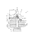
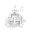
図1は本発明の実施例1に係るブレーキ装置1を示す平面図、図2は図1のA-A断面図、図3は図1のB-B断面図、図4は図1のC-C断面図、図5は図1のA-A断面図である。なお、図1~図4は制動状態における図であり、図5は解放状態における図である。
なお、図2に示す状態において、固定鉄心10の下面を一端面10a、上面を他端面10bと称し、可動鉄心20の上面を一端面20a、下面を他端面20bと称して説明をする。
図1は本発明の実施例1に係るブレーキ装置1を示す平面図、図2は図1のA-A断面図、図3は図1のB-B断面図、図4は図1のC-C断面図、図5は図1のA-A断面図である。なお、図1~図4は制動状態における図であり、図5は解放状態における図である。
なお、図2に示す状態において、固定鉄心10の下面を一端面10a、上面を他端面10bと称し、可動鉄心20の上面を一端面20a、下面を他端面20bと称して説明をする。
これらの図に示すように、ブレーキ装置1は、固定鉄心10と可動鉄心20を有している。固定鉄心10はボルト11により、固定部分である巻上機のフレーム12に固定設置されている(図1参照)。
可動鉄心20は、その一端面(上面)20aが、固定鉄心10の一端面(下面)10aに相対向する状態で配置されている(図2参照)。
可動鉄心20は、その一端面(上面)20aが、固定鉄心10の一端面(下面)10aに相対向する状態で配置されている(図2参照)。
固定鉄心10には、可動鉄心20側に突出するガイドピン13が取り付けられている。可動鉄心20には、ガイドピン13が挿通する孔が形成されており、この孔の内周面にはガイドピン13と摺接するドライベアリング21が配置されている(図3参照)。ガイドピン13がドライベアリング21に挿入されて摺動することにより、可動鉄心20はガイドピン13に沿いガイドされ、固定鉄心10に対して接近・離反移動することができるようになっている。
また、固定鉄心10には一端面10a側にのみ開口した穴が形成されており、この穴内には圧縮コイルばねである制動ばね22が挿入されている(図4参照)。このため、制動ばね22により、可動鉄心20には、固定鉄心10から可動鉄心20に向かう方向のばね力が付勢されている。
また固定鉄心10には、一端面(下面)10aから他端面(上面)10bに至るように貫通した孔10hが形成されている(図2~図5参照)。
また固定鉄心10には、一端面(下面)10aから他端面(上面)10bに至るように貫通した孔10hが形成されている(図2~図5参照)。
可動鉄心20の他端面(下面)20bには、ライニングホルダー23を介してライニング24が取り付けられている(図2,図3,図5参照)。ライニングホルダー23はボルト23aにより、可動鉄心20に固定されている。
固定鉄心10に対する可動鉄心20の接近・離反移動状態の詳細は後述するが、可動鉄心20が固定鉄心10から離れて、可動鉄心20の一端面(上面)20aと固定鉄心10の一端面(下面)10aとの間にギャップGが形成されたときには、ライニング24がブレーキドラムDに接触して制動状態となる(図2,図3参照)。
一方、可動鉄心20が固定鉄心10に近づき、可動鉄心20の一端面(上面)20aが固定鉄心10の一端面(下面)10aに接触すると、ライニング24とブレーキドラムDとの間にギャップGが形成され、制動が解放される(図5参照)。
一方、可動鉄心20が固定鉄心10に近づき、可動鉄心20の一端面(上面)20aが固定鉄心10の一端面(下面)10aに接触すると、ライニング24とブレーキドラムDとの間にギャップGが形成され、制動が解放される(図5参照)。
更にこのブレーキ装置1には、緩めボルト30と引き上げ機構40とで構成されるブレーキ解放機構50が取り付けられている。
緩めボルト30は、その一端部分(図2では下端部分)が可動鉄心20に係合している。この緩めボルト30は、固定鉄心10に形成された孔10hを貫通しており、更に、固定鉄心10の他端面(上面)10bよりも外側に突出する他端部分(上端部分)を有している。
固定鉄心10に形成された孔10hの内周面には、緩めボルト30に摺接するドライベアリング14が配置されている。このため緩めボルト30は、固定鉄心10に対して軸方向にスライド移動することができ、しかも、緩めボルト30の軸方向に対して直交する方向に揺れ動くことはない。
固定鉄心10に形成された孔10hの内周面には、緩めボルト30に摺接するドライベアリング14が配置されている。このため緩めボルト30は、固定鉄心10に対して軸方向にスライド移動することができ、しかも、緩めボルト30の軸方向に対して直交する方向に揺れ動くことはない。
乗りかごを昇降させる通常運転時においては、緩めボルト30は、図示しない電磁コイルにより、矢印A方向(可動鉄心20側から固定鉄心10側に向かう方向、図2,図3,図5参照)に引き上げられる。このため、緩めボルト30に係合する可動鉄心20は、制動ばね22のばね力に抗して固定鉄心10に近づき、可動鉄心20の一端面(上面)20aが固定鉄心10の一端面(下面)10aに接触し、ライニング24とブレーキドラムDとの間にギャップGが形成されて、制動が解放される(図5参照)。
一方、停電や地震などの非常時においては、電磁コイルへの通電が遮断されて電磁コイルによる矢印A方向への引き上げ力がなくなる。このため、可動鉄心20は制動ばね22のばね力により矢印B方向(固定鉄心10側から可動鉄心20側に向かう方向、図2,図3,図5参照)に付勢されて移動し、可動鉄心20の一端面(上面)20aと固定鉄心10の一端面(下面)10aとの間にギャップGが形成され、ライニング24がブレーキドラムDに接触して制動状態となる(図2,図3参照)。
引き上げ機構40は、停電や地震などの非常時において電磁コイルへの通電が遮断されてライニング24がブレーキドラムDに接触して制動状態になっているときに、緩めボルト30(ひいては可動鉄心20)を矢印A方向に引き上げ、ライニング24とブレーキドラムDとの間にギャップGを形成して制動を解放させるものである。
引き上げ機構40は、支持台41と、緩めレバー42と、支持ピン43-1,43-2と、ワイヤー44と、山アール座金45と、座金(平座金)46と、ナット47と、ロックナット48を主要部材として構成されている。
支持台41は、固定鉄心10の他端面(上面)10bに配置され、ボルト41aにより固定鉄心10にボルト固定されている。この例では、支持台41は、平面視(図1に示す平面状態)で見たときに、概略矩形であり、緩めボルト30を囲むように中央部が開いており、更に、緩めレバー42を囲むと共に緩めレバー42の揺動運動(回動運動)を許容するように一辺(図1では左側の辺)が開かれている。
支持台41には、本例では一対の支持ピン43-1,43-2が配置されている。支持ピン43-1,43-2は、緩めボルト30及び緩めレバー42を間に挟む状態で離間している。支持ピン43-1,43-2の軸心は相対向しており、支持ピン43-1の軸心を延長した部分に、支持ピン43-2の軸心がある。
緩めレバー42は、固定鉄心10の他端面(上面)10b側に配置されており、支持ピン43-1,43-2により回動自在に支持されている。このため支持ピン43-1,43-2の軸心の部分が、「てこの原理」での支点X1となる。この緩めレバー42には、緩めボルト30の他端部分(上端部分)が貫通する孔42hが形成されている(図3参照)。緩めレバー42の一端部分(図1では左端部分)にはワイヤー44が連結されている。緩めレバー42のうちワイヤー44が連結されている部分が、「てこの原理」での力点Z1となる。
なお、緩めレバー42は、ワイヤー44が接続されている部分が、固定鉄心10の他端面(上面)10bからはみ出しているが、ほとんどの部分は、固定鉄心10の他端面(上面)10bに位置するような寸法になっている。つまり緩めレバー42の軸方向長さが短くなるように寸法を制限している。
なお、緩めレバー42は、ワイヤー44が接続されている部分が、固定鉄心10の他端面(上面)10bからはみ出しているが、ほとんどの部分は、固定鉄心10の他端面(上面)10bに位置するような寸法になっている。つまり緩めレバー42の軸方向長さが短くなるように寸法を制限している。
緩めレバー42の上面(緩めレバー42から見て固定鉄心10とは反対側の面)には山アール座金45が固定設置されている。このとき、山アール座金45の山部分(山形の突出部分)が上方(山アール座金45から見て固定鉄心10とは反対側の方向)に向くように、山アール座金45の配置向きを設定している。
この山アール座金45には、孔45hが形成されており、緩めボルト30の他端部分(上端部分)が貫通している(図3参照)。
この山アール座金45には、孔45hが形成されており、緩めボルト30の他端部分(上端部分)が貫通している(図3参照)。
山アール座金45の上面側(山アール座金45から見て固定鉄心10とは反対側)には、緩めボルト30の他端部分(上端部分)が貫通する座金46が配置され、この座金46の上面側において、ナット47及びロックナット48が緩めボルト30の他端部分(上端部分)に螺合されている。このとき、山アール座金45と座金46との接触部分が、「てこの原理」での作用点Y1となる。
そして、緩めレバー42が固定鉄心10の他端面(上面)10bに対して平行になる状態まで、ナット47を締め込み、ロックナット48により固定している。
そして、緩めレバー42が固定鉄心10の他端面(上面)10bに対して平行になる状態まで、ナット47を締め込み、ロックナット48により固定している。
結局、緩めボルト30は、その一端部分(下端部分)が可動鉄心20に係合しており、また固定鉄心10を貫通している。更に、緩めボルト30の他端部分(上端部分)は、緩めレバー42,山アール座金45,座金46を貫通している。そして緩めボルト30の他端部分(上端部分)にはナット47及びロックナット48が螺合している。
上記構成のブレーキ解放機構50では、緩めレバー42の長さを規制して短くしていても、緩めレバー42によるレバー比を大きくする工夫をしている。即ち、力点Z1から支点X1までの長さL2が規制されていても、支点X1から作用点Y1までの長さL1を小さくすることにより(図1,図2参照)、レバー比(L2/L1)を大きくするような、工夫をしている。
この工夫とは、緩めレバー42の長手方向(力点Z1,作用点Y1,支点X1を結ぶα方向(図1参照))に関して、支持ピン43-1,43-2が緩めボルト30に近づくように、支持ピン43-1,43-2を配置していることである。より詳細に説明すると、緩めレバー42の長手方向αに関して、支持ピン43-1,43-2の軸心と緩めボルト30の軸心との間の長さL1が、支持ピン43-1,43-2の半径と緩めボルト30の他端部分(上端部分)の半径とを加算した長さよりも短くなるように、支持ピン43-1,43-2を配置していることである。
このような配置の工夫は、
(1)支持ピン43-1,43-2を、緩めレバー42の長手方向αに対して直交する方向である方向β(図1参照)に関して、支持ピン43-1,43-2を緩めボルト30から離れた位置に配置すること、
(2)緩めレバー42の長手方向αに関して、支持ピン43-1,43-2が緩めボルト30に近づくように、支持ピン43-1,43-2を配置していること、
により実現している。
(1)支持ピン43-1,43-2を、緩めレバー42の長手方向αに対して直交する方向である方向β(図1参照)に関して、支持ピン43-1,43-2を緩めボルト30から離れた位置に配置すること、
(2)緩めレバー42の長手方向αに関して、支持ピン43-1,43-2が緩めボルト30に近づくように、支持ピン43-1,43-2を配置していること、
により実現している。
この結果、緩めレバー42の長さを規制して短くしていても、支点X1から作用点Y1までの長さL1を小さくして、緩めレバー42のレバー比を大きくすることができる。このように、緩めレバー42の長さを短くしても、緩めレバー42のレバー比を大きくすることができる点が、本発明の大きな特徴の一つである。
なお仮に、支持ピン43-1,43-2の代わりに、支持ピン43-1,43-2と同じ太さの1本の支持ピンを、支持ピン43-1の位置から支持ピン43-2の位置にまで配置しようとしても、この1本の支持ピンは緩めボルト30と干渉してしまい、配置することはできない。
なお本実施例1では、緩めレバー42を2つの支持ピン43-1,43-2により両持ち支持しているが、支持ピン43-1,43-2のうちの一方の支持ピンにより緩めレバー42を片持ち支持する構造を採用することも可能である。
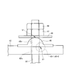
次に、このような構成となっているブレーキ装置1のうち、緩めボルト30と引き上げ機構40から成るブレーキ解放機構50の作動状態を、図1~図5のみならず、図2の状態(制動状態)における要部の拡大説明図である図6と、図5の状態(解放状態)における要部の拡大説明図である図7を用いて説明する。
図2に示す制動状態のときに、ワイヤー44を上方(矢印γ方向、図2参照)に引き上げると、緩めレバー42は、支持ピン43-1,43-2により支持された点(支点X1)を回動中心として回動する。
緩めレバー42が回動すると、緩めレバー42に固定された山アール座金45が座金46を押し上げ、ナット47を介して緩めボルト30も押し上げられ、緩めボルト30が係合する可動鉄心20が制動ばね22のばね力に抗して上方に移動して固定鉄心10に接触し、ライニング24とブレーキドラムDとの間に隙間Gが発生し、ブレーキが解放する(図5参照)。
緩めレバー42が回動すると、緩めレバー42に固定された山アール座金45が座金46を押し上げ、ナット47を介して緩めボルト30も押し上げられ、緩めボルト30が係合する可動鉄心20が制動ばね22のばね力に抗して上方に移動して固定鉄心10に接触し、ライニング24とブレーキドラムDとの間に隙間Gが発生し、ブレーキが解放する(図5参照)。
緩めレバー42が回動しているときには、山アール座金45と座金46との接触点が作用点Y1となる。そして、緩めレバー42が回動していくにつれて、山アール座金45と座金46との接触点(作用点Y1)は、山アール座金45の山部分(山形の突出部分)の頂部(図6の状態)から裾部(図7の状態)に向かって摺動しつつ移動してくる。
このとき、緩めボルト30の軸方向に沿う押上げ力(鉛直分力)の他に、鉛直分力に対して直交する水平分力も発生し、この水平分力が緩めボルト30に作用する。しかし、緩めボルト30はドライベアリング14により支持されているため、緩めボルト30が傾くことはない。したがって、緩めレバー42の回動に伴い、緩めボルト30はA方向にスムーズに移動していく。
このとき、緩めボルト30の軸方向に沿う押上げ力(鉛直分力)の他に、鉛直分力に対して直交する水平分力も発生し、この水平分力が緩めボルト30に作用する。しかし、緩めボルト30はドライベアリング14により支持されているため、緩めボルト30が傾くことはない。したがって、緩めレバー42の回動に伴い、緩めボルト30はA方向にスムーズに移動していく。
山アール座金45と座金46との接触点(作用点Y1)が、山アール座金45の山部分の頂部から裾部に向かって摺動しつつ移動していくときには、作用点Y1には滑り摩擦が発生する。しかし、このときの摺動は、山アール座金45の滑らかな湾曲面(円弧面)と座金46の平面との間での摺動であるため、発生する摩擦力は小さく、この摩擦力は実用上許容できる程度の小さな値である。
また、支点X1で発生する摩擦力も極めて小さい。更に、緩めボルト30とドライベアリング14とが摺動する摺動部では、接触面積が広く面圧が低くなるので、ここでの摺動抵抗は小さい。
更に、2つのレバーを採用した従来のブレーキ解放機構に対して、本実施例のブレーキ解放機構50では、レバー(緩めレバー42)が一つであるので摩擦発生箇所が少なくなり摺動抵抗が低下する。
また、支点X1で発生する摩擦力も極めて小さい。更に、緩めボルト30とドライベアリング14とが摺動する摺動部では、接触面積が広く面圧が低くなるので、ここでの摺動抵抗は小さい。
更に、2つのレバーを採用した従来のブレーキ解放機構に対して、本実施例のブレーキ解放機構50では、レバー(緩めレバー42)が一つであるので摩擦発生箇所が少なくなり摺動抵抗が低下する。
上述したように、ブレーキ装置1が制動状態になっているときに、ワイヤー44を引き上げることにより、ブレーキ装置1を解放状態にすることができる。
しかも、緩めレバー42のレバー比が大きいので、ワイヤー44の引き上げ力が小さくても、緩めレバー42をスムーズに回動させることができ、ブレーキ装置1を小さな手動操作力により解放状態にすることができる。
また、緩めレバー42のレバー比が大きくなるような工夫をしているので、緩めレバー42の長さを制限することができ、引き上げ機構40を含むブレーキ解放機構50の大きさ、ひいてはブレーキ装置1の大きさを小さくすることができ、更にエレベータの巻上機等の小型化に寄与することができる。
しかも、緩めレバー42のレバー比が大きいので、ワイヤー44の引き上げ力が小さくても、緩めレバー42をスムーズに回動させることができ、ブレーキ装置1を小さな手動操作力により解放状態にすることができる。
また、緩めレバー42のレバー比が大きくなるような工夫をしているので、緩めレバー42の長さを制限することができ、引き上げ機構40を含むブレーキ解放機構50の大きさ、ひいてはブレーキ装置1の大きさを小さくすることができ、更にエレベータの巻上機等の小型化に寄与することができる。
〔実施例2〕
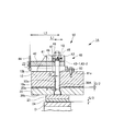
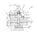
次に本発明の実施例2に係るブレーキ装置1Aを説明する。図8はブレーキ装置1Aを示す平面図、図9は図8のD-D断面図、図10は図8のE-E断面図、図11,図12は図8のD-D断面図である。なお、図8~図10は半分解放状態における図であり、図11は制動状態における図であり、図12は解放状態における図である。
次に本発明の実施例2に係るブレーキ装置1Aを説明する。図8はブレーキ装置1Aを示す平面図、図9は図8のD-D断面図、図10は図8のE-E断面図、図11,図12は図8のD-D断面図である。なお、図8~図10は半分解放状態における図であり、図11は制動状態における図であり、図12は解放状態における図である。
実施例2のブレーキ装置1Aは、実施例1のブレーキ装置1を変形したものである。具体的には、実施例1で用いていたドライベアリング14を無くすと共に、実施例1で用いていた緩めボルト30の代わりに緩めボルト30Aを採用し、新たな部材としてカラー60を用いた。他の部分の構成は基本的に、実施例1と同様である。
固定鉄心10の他端面(上面)10bには、孔10hと同心状態となるように、カラー60が固定されている。つまり、カラー60は、孔10hのうち、引き上げ機構40側の開口端に配置されている。
緩めボルト30Aは、その一端部分(下端部分)が可動鉄心20に係合しており、また固定鉄心10の孔10h及びカラー60を貫通している。更に、緩めボルト30Aの他端部分(上端部分)は、緩めレバー42,山アール座金45,座金(平座金)46を貫通している。そして緩めボルト30Aの他端部分(上端部分)にはナット47及びロックナット48が螺合している。
緩めボルト30Aの一端部分(下端部分)は、実施例1の緩めボルト30の下端部分よりも細くなっている。このため、緩めボルト30Aと固定鉄心10の孔10hの間に隙間が形成される。また、緩めボルト30Aと可動鉄心20との間の隙間Pや、緩めボルト30Aとカラー60との間の隙間Qは、緩めボルト30Aが軸方向に沿いスムーズに移動することができ、且つ、緩めボルト30Aの軸心位置をなるべく中心部にとどめることができる隙間寸法になっている。
なお、支持ピン43-1,43-2は、固定鉄心10の他端面(上面)10bからみて、実施例1の配置位置よりも上方(他端面10bから離れた位置)に配置されている。具体的には、緩めレバー42が固定鉄心10の上面(他端面)10bに対して平行になったときに、支点X2(支持ピン43-1,43-2の軸心)と作用点Y2(山アール座金45と座金46との接触点)とを結ぶ線が、固定鉄心10の上面(他端面)10bに対して平行になるように、支持ピン43-1,43-2の配置位置(高さ位置)が設定されている(図9参照)。
上記のように、
(1)緩めボルト30Aが軸方向に沿いスムーズに移動することができ、且つ、緩めボルト30Aの軸心位置をなるべく中心部にとどめることができるようにした、隙間P,Qを確保すると共に、
(2)緩めレバー42が固定鉄心10の上面(他端面)10bに対して平行になったときに、支点X2と作用点Y2とを結ぶ線が、固定鉄心10の上面(他端面)10bに対して平行になるように、支点X2と作用点Y2の配置位置、即ち支持ピン43-1,43-2の配置位置や山アール座金45と座金46との接触点の配置位置を設定した構成が、
実施例2における特徴的な構成になっている。
(1)緩めボルト30Aが軸方向に沿いスムーズに移動することができ、且つ、緩めボルト30Aの軸心位置をなるべく中心部にとどめることができるようにした、隙間P,Qを確保すると共に、
(2)緩めレバー42が固定鉄心10の上面(他端面)10bに対して平行になったときに、支点X2と作用点Y2とを結ぶ線が、固定鉄心10の上面(他端面)10bに対して平行になるように、支点X2と作用点Y2の配置位置、即ち支持ピン43-1,43-2の配置位置や山アール座金45と座金46との接触点の配置位置を設定した構成が、
実施例2における特徴的な構成になっている。
そして、緩めレバー42が固定鉄心10の上面(他端面)10bに対して平行になり、固定鉄心10と可動鉄心20との隙間がG/2となり、且つ、ライニング24とブレーキドラムDとの隙間がG/2となる状態まで、ナット47を締め込み、ロックナット48により固定している(図9,図10参照)。
次に、このような構成となっているブレーキ装置1Aのうち、緩めボルト30Aと引き上げ機構40から成るブレーキ解放機構50の作動状態を説明する。
図11に示す制動状態のときに、ワイヤー44を上方(矢印γ方向)に引き上げると、緩めレバー42は、支持ピン43-1,43-2により支持された点(支点X2)を回動中心として回動する。
緩めレバー42が回動すると、緩めレバー42に固定された山アール座金45が座金46を押し上げナット47を介して緩めボルト30Aも押し上げられ、緩めボルト30Aが係合する可動鉄心20が制動ばね22のばね力に抗して上方に移動して固定鉄心10に接触し、ライニング24とブレーキドラムDとの間に隙間Gが発生し、ブレーキが解放する(図12参照)。
緩めレバー42が回動すると、緩めレバー42に固定された山アール座金45が座金46を押し上げナット47を介して緩めボルト30Aも押し上げられ、緩めボルト30Aが係合する可動鉄心20が制動ばね22のばね力に抗して上方に移動して固定鉄心10に接触し、ライニング24とブレーキドラムDとの間に隙間Gが発生し、ブレーキが解放する(図12参照)。
緩めレバー42が回動しているときには、山アール座金45と座金46との接触点が作用点Y2となる。そして、緩めレバー42が回動していくにつれて、支点X2を中心として、山アール座金45と座金46との接触点(作用点Y2)は、山アール座金45の山部分(山形の突出部分)に沿い転がりつつ移動してくる。
このとき、緩めボルト30Aの軸方向に沿う押上げ力(鉛直分力)の他に、鉛直分力に対して直交する水平分力も発生する。この水平分力が緩めボルト30Aに作用して緩めボルト30Aは微小であるが傾くと共に、作用点Y2が山アール座金45の山部分(円弧状になっている山形の突出部)を転がって移動する。このため、作用点Y2が移動していく際に発生する摩擦力は極めて小さくなる。つまり、緩めレバー42が回動していく際に作用点Y2は摺動することなく転がるため、作用点Y2に滑りが発生しない。また実施例2では、実施例1で用いていたドライベアリング14を用いていないため、ドライベアリングでの摩擦損失も発生しないので、大半の滑り損失がなくなる。このため、ワイヤー44を引き上げるのに要する手動操作力は、実施例1よりも更に低減する。
なお、ワイヤー44を上方(矢印γ方向)に引き上げることにより、制動状態(図11)から解放状態(図12)になるまで緩めボルト30Aは上向きに移動するが、その移動量は通常0.5mm程度と極めて小さいこと、及び、緩めボルト30Aの上方への動き(移動)は支点X2と作用点Y2を結ぶ線に対してほぼ直角であることから、緩めボルト30Aの水平方向の動き(緩めボルト30Aの傾き)は極めて小さく、実用上無視できる大きさである。
実施例2では、緩めボルト30Aと固定鉄心10の孔10hの間は隙間であるため、緩めボルト30A及び孔10hの加工精度は、それほどの精度は不要となり、加工が容易である。つまり、実施例1の孔10hはドライベアリング14を保持するため高精度な加工が必要であるが、実施例2の孔10hは一般のボルト通し穴でよいので加工費が低減できる。
また、実施例1の緩めボルト30はドライベアリング14との摺動面を有するため、専用の形状寸法と高精度な加工が必要であり高価であるが、実施例2の緩めボルト30Aは、通常の市販品を使用できるので安価である。
実施例2のブレーキ装置は、実施例1のブレーキ装置よりも更に、力の損失が少なくなると共に、ブレーキ装置の小型化、ひいてはエレベータの巻上機等の小型化に寄与することができる。
また、実施例1の緩めボルト30はドライベアリング14との摺動面を有するため、専用の形状寸法と高精度な加工が必要であり高価であるが、実施例2の緩めボルト30Aは、通常の市販品を使用できるので安価である。
実施例2のブレーキ装置は、実施例1のブレーキ装置よりも更に、力の損失が少なくなると共に、ブレーキ装置の小型化、ひいてはエレベータの巻上機等の小型化に寄与することができる。
〔実施例3〕
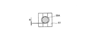
次に本発明の実施例3に係るブレーキ装置1Bを説明する。図13はブレーキ装置1Bを示す平面図、図14は図13のF-F断面図、図15は図14のH-H断面図、図16,図17は図13のF-F断面図である。なお、図13~図15は半分解放状態における図であり、図16は制動状態における図であり、図17は解放状態における図である。
次に本発明の実施例3に係るブレーキ装置1Bを説明する。図13はブレーキ装置1Bを示す平面図、図14は図13のF-F断面図、図15は図14のH-H断面図、図16,図17は図13のF-F断面図である。なお、図13~図15は半分解放状態における図であり、図16は制動状態における図であり、図17は解放状態における図である。
実施例3のブレーキ装置1Bは、実施例2のブレーキ装置1Aを変形したものである。具体的には、実施例2で用いていたカラー60を無くすと共に、実施例2で用いていた座金(平座金)46の代わりに谷アール座金61を採用している。他の部分の構成は基本的に、実施例2と同様である。
緩めボルト30Aは、その一端部分(下端部分)が可動鉄心20に係合しており、また固定鉄心10の孔10hを貫通している。更に、緩めボルト30Aの他端部分(上端部分)は、緩めレバー42,山アール座金45,谷アール座金61を貫通している。そして緩めボルト30Aの他端部分(上端部分)にはナット47及びロックナット48が螺合している。
緩めレバー42の上面に固定設置された山アール座金45は、その山部分(山形の突出部分)が上方(山アール座金45からみて、固定鉄心10とは反対側の方向)に向くように配置されている。
谷アール座金61は、山アール座金45の上面側に配置されると共に、緩めボルト30Aの他端部分(上端部分)が貫通している。この谷アール座金61は、その谷部分が、山アール座金45の山部分に向くように配置されている。そして、山アール座金45の山部分が、谷アール座金61の谷部分に嵌入し、円弧状の山部分が円弧状の谷部分に面接触する部分が作用点Y3となる。
谷アール座金61は、山アール座金45の上面側に配置されると共に、緩めボルト30Aの他端部分(上端部分)が貫通している。この谷アール座金61は、その谷部分が、山アール座金45の山部分に向くように配置されている。そして、山アール座金45の山部分が、谷アール座金61の谷部分に嵌入し、円弧状の山部分が円弧状の谷部分に面接触する部分が作用点Y3となる。
緩めボルト30Aと固定鉄心10の孔10hの間には隙間が形成されている。また、緩めボルト30Aと可動鉄心20との間の隙間Pや、緩めボルト30Aと谷アール座金61の孔との間の隙間R(図15参照)は、緩めボルト30Aが軸方向に沿いスムーズに移動することができ、且つ、緩めボルト30Aの軸心位置をなるべく中心部にとどめることができる隙間寸法になっている。
実施例3では、実施例2と同様に、緩めレバー42が固定鉄心10の上面(他端面)10bに対して平行になったときに、支点X3(支持ピン43-1,43-2の軸心)と作用点Y3(山アール座金45と谷アール座金61との接触点の頂部)とを結ぶ線が、固定鉄心10の上面(他端面)10bに対して平行になるように、支持ピン43-1,43-2の配置位置が設定されている(図14参照)。更に、緩めレバー42が固定鉄心10の上面(他端面)10bに対して平行になり、固定鉄心10と可動鉄心20との隙間がG/2となり、且つ、ライニング24とブレーキドラムDとの隙間がG/2となる状態まで、ナット47を締め込み、ロックナット48により固定している(図13,図14参照)。
次に、このような構成となっているブレーキ装置1Bのうち、緩めボルト30Aと引き上げ機構40から成るブレーキ解放機構50の作動状態を説明する。
図16に示す制動状態のときに、ワイヤー44を上方(矢印γ方向)に引き上げると、緩めレバー42は、支持ピン43-1,43-2により支持された点(支点X3)を回動中心として回動する。
緩めレバー42が回動すると、緩めレバー42に固定された山アール座金45が谷アール座金61を押し上げ、ナット47を介して緩めボルト30Aも押し上げられ、緩めボルト30Aが係合する可動鉄心20が制動ばね22のばね力に抗して上方に移動して固定鉄心10に接触し、ライニング24とブレーキドラムDとの間に隙間Gが発生し、ブレーキが解放する(図17参照)。
緩めレバー42が回動すると、緩めレバー42に固定された山アール座金45が谷アール座金61を押し上げ、ナット47を介して緩めボルト30Aも押し上げられ、緩めボルト30Aが係合する可動鉄心20が制動ばね22のばね力に抗して上方に移動して固定鉄心10に接触し、ライニング24とブレーキドラムDとの間に隙間Gが発生し、ブレーキが解放する(図17参照)。
緩めレバー42が回動しているときには、山アール座金45の山部分が、谷アール座金61の谷部分に嵌入し、円弧状の山部分が円弧状の谷部分に面接触する部分が作用点Y3となる。緩めレバー42の回動に伴う作用点Y3の上方への動きは通常0.5mmと小さいこと、及び、緩めボルト30Aの上方への動き(移動)は支点X2と作用点Y2を結ぶ線に対してほぼ直角であることから、緩めボルト30Aの水平方向の動き(緩めボルト30Aの傾き)は極めて小さいので滑り量も小さい。また、作用点Y3は面接触の滑りであるため、接触面圧や潤滑を考慮することにより、摩擦を小さく抑えることができ、ワイヤー44を引き上げるのに要する手動操作力を低減することができる。
したがって、実施例3のブレーキ装置は、実施例1のブレーキ装置よりも小さな手動操作力でブレーキを解放することができる。
実施例3のブレーキ装置は、実施例1のブレーキ装置よりも更に、力の損失が少なくなると共に、ブレーキ装置の小型化、ひいてはエレベータの巻上機等の小型化に寄与することができる。
したがって、実施例3のブレーキ装置は、実施例1のブレーキ装置よりも小さな手動操作力でブレーキを解放することができる。
実施例3のブレーキ装置は、実施例1のブレーキ装置よりも更に、力の損失が少なくなると共に、ブレーキ装置の小型化、ひいてはエレベータの巻上機等の小型化に寄与することができる。
〔実施例4〕
次に本発明の実施例4に係るブレーキ装置1Cを、図18を参照して説明する。
実施例4のブレーキ装置1Cは、実施例2のブレーキ装置1Aに、がた防止ばね62を備えたものである。がた防止ばね62は、圧縮コイルばねである。
次に本発明の実施例4に係るブレーキ装置1Cを、図18を参照して説明する。
実施例4のブレーキ装置1Cは、実施例2のブレーキ装置1Aに、がた防止ばね62を備えたものである。がた防止ばね62は、圧縮コイルばねである。
緩めレバー42の下端辺(固定鉄心10側の辺)には、凹部42aを形成している。がた防止ばね62は、上端が緩めレバー42の凹部42aに接し、下端が固定鉄心10の他端面(上面)10bに接し、凹部42aと他端面(上面)10bとの間に圧縮状態で挿入されている。
がた防止ばね62のばね力は、ブレーキ解除機構50の可動部(緩めレバー42、山アール座金45、座金46、ナット47、ロックナット48、緩めボルト30A)の重さ及びその摺動部の摩擦抵抗に打ち勝って、各部のがたを防止できる強さに設定している。
がた防止ばね62のばね力は、ブレーキ解除機構50の可動部(緩めレバー42、山アール座金45、座金46、ナット47、ロックナット48、緩めボルト30A)の重さ及びその摺動部の摩擦抵抗に打ち勝って、各部のがたを防止できる強さに設定している。
がた防止ばね62が無い場合においては、ブレーキ解除機構50の支点や作用点に微妙な隙間があるため、ブレーキ本体の振動等でブレーキ解除機構50が振動して騒音の問題が発生することがある。また、比較的大きな振動が長期にわたる場合は、振動の衝撃で支点や作用点の異常な摩耗が発生する恐れがある。
がた防止ばね62を備えることにより、上記の問題を解消することができる。
がた防止ばね62を備えることにより、上記の問題を解消することができる。
なお、実施例1や実施例3のブレーキ装置に、がた防止ばね62を備えるようにすることも可能である。
〔実施例5〕
次に本発明の実施例5に係るブレーキ装置1Dを、図19を参照して説明する。
実施例5のブレーキ装置1Dは、実施例4のブレーキ装置1Cを改良したものである。
次に本発明の実施例5に係るブレーキ装置1Dを、図19を参照して説明する。
実施例5のブレーキ装置1Dは、実施例4のブレーキ装置1Cを改良したものである。
実施例5のブレーキ装置1Dでは、緩めボルト30Aの下端面には穴31が形成されており、この穴31内にがた防止ばね63を備えている。つまり、がた防止ばね62のみならず、更に、圧縮コイルばねであるがた防止ばね63を備えている。
がた防止ばね63は、緩めボルト30Aを、可動鉄心20側から固定鉄心10側に向かって付勢する。このがた防止ばね63のばね力は、ナット47、ロックナット48、緩めボルト30Aの重さに打ち勝って、がたを防止できる強さに設定している。一方、がた防止ばね62のばね力は、緩めレバー42、山アール座金45、座金46の重さに打ち勝って、がたを防止できる強さに軽減することができる。
このようにがた防止ばね63を備えたため、支点や作用点の摩擦抵抗が軽減され、効果的かつ確実にがたの発生を防止することができる。
がた防止ばね63は、緩めボルト30Aを、可動鉄心20側から固定鉄心10側に向かって付勢する。このがた防止ばね63のばね力は、ナット47、ロックナット48、緩めボルト30Aの重さに打ち勝って、がたを防止できる強さに設定している。一方、がた防止ばね62のばね力は、緩めレバー42、山アール座金45、座金46の重さに打ち勝って、がたを防止できる強さに軽減することができる。
このようにがた防止ばね63を備えたため、支点や作用点の摩擦抵抗が軽減され、効果的かつ確実にがたの発生を防止することができる。
実施例5では、がた防止ばね62のみならずがた防止ばね63を採用することにより、実施例4よりも効果的に、がたの防止や騒音の低減を図ることができる。
なお、実施例1~3のブレーキ装置に、がた防止ばね63を備えるようにすることも可能である。
本発明は、手動操作により制動状態を解放することができるブレーキ装置に利用することができる。
1、1A、1B、1C、1D ブレーキ装置
10 固定鉄心
10a 一端面
10b 他端面
10h 孔
11 ボルト
12 フレーム
13 ガイドピン
14 ドライベアリング
20 可動鉄心
20a 一端面
20b 他端面
21 ドライベアリング
22 制動ばね
23 ライニングホルダー
23a ボルト
24 ライニング
30,30A 緩めボルト
31 穴
40 引き上げ機構
41 支持台
41a ボルト
42 緩めレバー
42a 凹部
42h 孔
43-1,43-2 支持ピン
44 ワイヤー
45 山アール座金
45h 孔
46 座金
47 ナット
48 ロックナット
50 ブレーキ解放機構
60 カラー
61 谷アール座金
62、63 がた防止ばね
D ブレーキドラム
10 固定鉄心
10a 一端面
10b 他端面
10h 孔
11 ボルト
12 フレーム
13 ガイドピン
14 ドライベアリング
20 可動鉄心
20a 一端面
20b 他端面
21 ドライベアリング
22 制動ばね
23 ライニングホルダー
23a ボルト
24 ライニング
30,30A 緩めボルト
31 穴
40 引き上げ機構
41 支持台
41a ボルト
42 緩めレバー
42a 凹部
42h 孔
43-1,43-2 支持ピン
44 ワイヤー
45 山アール座金
45h 孔
46 座金
47 ナット
48 ロックナット
50 ブレーキ解放機構
60 カラー
61 谷アール座金
62、63 がた防止ばね
D ブレーキドラム
Claims (6)
- 固定鉄心に対して可動鉄心が離れていくことにより制動状態となり、固定鉄心に対して可動鉄心が接近していくことにより解放状態となるブレーキ装置において、
前記可動鉄心に係合すると共に、前記固定鉄心に形成された孔を貫通する緩めボルトと、
前記緩めボルトのうち前記固定鉄心を貫通して前記固定鉄心の外側に突出した部分を、前記可動鉄心側から前記固定鉄心側に引くことにより解放状態にする引き上げ機構を有しており、
前記引き上げ機構は、
緩めレバーと、
前記緩めレバーを回動自在に支持する支持ピンと、
前記緩めボルトに取り付けられている座金と、
前記緩めレバーに固定設置されると共に、山形の突出部が前記座金のうち前記固定鉄心側の面に接する山アール座金とを有し、
前記緩めレバーの長手方向に関して、前記支持ピンの軸心と前記緩めボルトの軸心との間の長さが、前記支持ピンの半径と前記緩めボルトのうち前記固定鉄心の外側に突出した部分の半径とを加算した長さよりも短くなる位置に、前記支持ピンを配置していることを特徴とするブレーキ装置。 - 請求項1において、
前記座金は平座金であり、
前記固定鉄心に形成された前記孔には、前記緩めボルトに摺接するドライベアリングが配置されていることを特徴とするブレーキ装置。 - 請求項1において、
前記固定鉄心に形成された前記孔のうち、前記引き上げ機構側の開口端には、前記緩めボルトが隙間を空けて貫通するカラーが配置されており、
前記固定鉄心に形成された前記孔と、前記孔を貫通する前記緩めボルトとの間には隙間が形成され、
前記緩めレバーを前記固定鉄心の面に対して平行にしたときに、前記座金と前記山型座金の接触点と前記支持ピンの軸心とを結ぶ線が、前記固定鉄心の面に対して平行になるように、前記支持ピンの高さ位置を設定していることを特徴とするブレーキ装置。 - 請求項1において、
前記座金は谷アール座金であり、前記山アール座金の山部分が前記谷アール座金の谷部分に嵌入しており、
前記固定鉄心に形成された前記孔と、前記孔を貫通する前記緩めボルトとの間には隙間が形成され、
前記緩めレバーを前記固定鉄心の面に対して平行にしたときに、前記座金と前記山型座金の接触点と前記支持ピンの軸心とを結ぶ線が、前記固定鉄心の面に対して平行になるように、前記支持ピンの高さ位置を設定していることを特徴とするブレーキ装置。 - 請求項1において、
前記緩めレバーと前記固定鉄心の間に、第1のがた防止ばねを配置したことを特徴とするブレーキ装置。 - 請求項1において、
前記緩めボルトを、前記可動鉄心側から前記固定鉄心側に向かって付勢する、第2のがた防止ばねを配置したことを特徴とするブレーキ装置。
Applications Claiming Priority (2)
| Application Number | Priority Date | Filing Date | Title |
|---|---|---|---|
| JP2015012874A JP6002940B2 (ja) | 2015-01-27 | 2015-01-27 | ブレーキ装置 |
| JP2015-012874 | 2015-01-27 |
Publications (1)
| Publication Number | Publication Date |
|---|---|
| WO2016121783A1 true WO2016121783A1 (ja) | 2016-08-04 |
Family
ID=56543394
Family Applications (1)
| Application Number | Title | Priority Date | Filing Date |
|---|---|---|---|
| PCT/JP2016/052242 Ceased WO2016121783A1 (ja) | 2015-01-27 | 2016-01-27 | ブレーキ装置 |
Country Status (2)
| Country | Link |
|---|---|
| JP (1) | JP6002940B2 (ja) |
| WO (1) | WO2016121783A1 (ja) |
Families Citing this family (1)
| Publication number | Priority date | Publication date | Assignee | Title |
|---|---|---|---|---|
| JP7433371B2 (ja) * | 2022-07-06 | 2024-02-19 | 三菱電機ビルソリューションズ株式会社 | 巻上機ブレーキ装置 |
Citations (3)
| Publication number | Priority date | Publication date | Assignee | Title |
|---|---|---|---|---|
| JPS6340639U (ja) * | 1986-09-02 | 1988-03-16 | ||
| JP2002372078A (ja) * | 2001-06-15 | 2002-12-26 | Ogura Clutch Co Ltd | 無励磁作動ブレーキ |
| JP2009545705A (ja) * | 2006-04-07 | 2009-12-24 | ツェーハーエル・マイヤー・ゲーエムベーハー・ウント・コンパニー・カーゲー | 2系統方形ブレーキの形の電磁解放式ばね圧ブレーキ |
-
2015
- 2015-01-27 JP JP2015012874A patent/JP6002940B2/ja not_active Expired - Fee Related
-
2016
- 2016-01-27 WO PCT/JP2016/052242 patent/WO2016121783A1/ja not_active Ceased
Patent Citations (3)
| Publication number | Priority date | Publication date | Assignee | Title |
|---|---|---|---|---|
| JPS6340639U (ja) * | 1986-09-02 | 1988-03-16 | ||
| JP2002372078A (ja) * | 2001-06-15 | 2002-12-26 | Ogura Clutch Co Ltd | 無励磁作動ブレーキ |
| JP2009545705A (ja) * | 2006-04-07 | 2009-12-24 | ツェーハーエル・マイヤー・ゲーエムベーハー・ウント・コンパニー・カーゲー | 2系統方形ブレーキの形の電磁解放式ばね圧ブレーキ |
Also Published As
| Publication number | Publication date |
|---|---|
| JP2016137958A (ja) | 2016-08-04 |
| JP6002940B2 (ja) | 2016-10-05 |
Similar Documents
| Publication | Publication Date | Title |
|---|---|---|
| JP5112342B2 (ja) | エレベータの安全装置 | |
| CN108367892B (zh) | 鲁棒性电气安全致动模块 | |
| JP5409788B2 (ja) | エレベータの直動式ドラムブレーキ装置 | |
| JP5824149B2 (ja) | エレベータの電磁ブレーキ解放装置 | |
| CN107848761B (zh) | 电梯用曳引机和电梯 | |
| JPWO2008149413A1 (ja) | エレベータの安全装置 | |
| JP2014111970A (ja) | 電磁ブレーキ装置 | |
| JP4400956B2 (ja) | エレベータの安全装置 | |
| CN112088138A (zh) | 电梯的安全装置和电梯的安全系统 | |
| CN111377339B (zh) | 电梯轿厢停车制动器和电梯 | |
| JP5443929B2 (ja) | 巻上機 | |
| JP4952296B2 (ja) | エレベータ巻上機用ブレーキの解放装置及びそのブレーキの解放方法 | |
| JP6687052B2 (ja) | エレベータ用巻上機、および巻上機の設置方法 | |
| CN205312816U (zh) | 电梯以及电梯用紧急停止机构的锁定装置 | |
| JPWO2018216111A1 (ja) | エレベータ用ブレーキ開放装置 | |
| JP6002940B2 (ja) | ブレーキ装置 | |
| JP4807163B2 (ja) | エレベーターの安全装置 | |
| CN1993289B (zh) | 电梯用曳引装置 | |
| JP4601687B2 (ja) | エレベーター用巻上機 | |
| JP4812544B2 (ja) | エレベーター用巻上機 | |
| CN114988312B (zh) | 制动器释放装置 | |
| JP2008195521A (ja) | エレベータ装置 | |
| JP5470290B2 (ja) | エレベーター用巻上機及びエレベーター装置 | |
| CN104555790A (zh) | 适用于机械搅拌铁水脱硫的防坠升降小车 | |
| CN108349704B (zh) | 电梯装置 |
Legal Events
| Date | Code | Title | Description |
|---|---|---|---|
| 121 | Ep: the epo has been informed by wipo that ep was designated in this application |
Ref document number: 16743386 Country of ref document: EP Kind code of ref document: A1 |
|
| NENP | Non-entry into the national phase |
Ref country code: DE |
|
| 122 | Ep: pct application non-entry in european phase |
Ref document number: 16743386 Country of ref document: EP Kind code of ref document: A1 |