WO2016121694A1 - トランジションピース、これを備える燃焼器、及び燃焼器を備えるガスタービン - Google Patents
トランジションピース、これを備える燃焼器、及び燃焼器を備えるガスタービン Download PDFInfo
- Publication number
- WO2016121694A1 WO2016121694A1 PCT/JP2016/052021 JP2016052021W WO2016121694A1 WO 2016121694 A1 WO2016121694 A1 WO 2016121694A1 JP 2016052021 W JP2016052021 W JP 2016052021W WO 2016121694 A1 WO2016121694 A1 WO 2016121694A1
- Authority
- WO
- WIPO (PCT)
- Prior art keywords
- passage
- passages
- downstream
- upstream
- transition piece
- Prior art date
- Legal status (The legal status is an assumption and is not a legal conclusion. Google has not performed a legal analysis and makes no representation as to the accuracy of the status listed.)
- Ceased
Links
Images


Classifications
-
- F—MECHANICAL ENGINEERING; LIGHTING; HEATING; WEAPONS; BLASTING
- F23—COMBUSTION APPARATUS; COMBUSTION PROCESSES
- F23R—GENERATING COMBUSTION PRODUCTS OF HIGH PRESSURE OR HIGH VELOCITY, e.g. GAS-TURBINE COMBUSTION CHAMBERS
- F23R3/00—Continuous combustion chambers using liquid or gaseous fuel
- F23R3/02—Continuous combustion chambers using liquid or gaseous fuel characterised by the air-flow or gas-flow configuration
- F23R3/04—Air inlet arrangements
- F23R3/06—Arrangement of apertures along the flame tube
-
- F—MECHANICAL ENGINEERING; LIGHTING; HEATING; WEAPONS; BLASTING
- F02—COMBUSTION ENGINES; HOT-GAS OR COMBUSTION-PRODUCT ENGINE PLANTS
- F02C—GAS-TURBINE PLANTS; AIR INTAKES FOR JET-PROPULSION PLANTS; CONTROLLING FUEL SUPPLY IN AIR-BREATHING JET-PROPULSION PLANTS
- F02C7/00—Features, components parts, details or accessories, not provided for in, or of interest apart form groups F02C1/00 - F02C6/00; Air intakes for jet-propulsion plants
- F02C7/12—Cooling of plants
- F02C7/16—Cooling of plants characterised by cooling medium
- F02C7/18—Cooling of plants characterised by cooling medium the medium being gaseous, e.g. air
-
- F—MECHANICAL ENGINEERING; LIGHTING; HEATING; WEAPONS; BLASTING
- F01—MACHINES OR ENGINES IN GENERAL; ENGINE PLANTS IN GENERAL; STEAM ENGINES
- F01D—NON-POSITIVE DISPLACEMENT MACHINES OR ENGINES, e.g. STEAM TURBINES
- F01D25/00—Component parts, details, or accessories, not provided for in, or of interest apart from, other groups
- F01D25/08—Cooling; Heating; Heat-insulation
- F01D25/12—Cooling
-
- F—MECHANICAL ENGINEERING; LIGHTING; HEATING; WEAPONS; BLASTING
- F01—MACHINES OR ENGINES IN GENERAL; ENGINE PLANTS IN GENERAL; STEAM ENGINES
- F01D—NON-POSITIVE DISPLACEMENT MACHINES OR ENGINES, e.g. STEAM TURBINES
- F01D25/00—Component parts, details, or accessories, not provided for in, or of interest apart from, other groups
- F01D25/24—Casings; Casing parts, e.g. diaphragms, casing fastenings
-
- F—MECHANICAL ENGINEERING; LIGHTING; HEATING; WEAPONS; BLASTING
- F01—MACHINES OR ENGINES IN GENERAL; ENGINE PLANTS IN GENERAL; STEAM ENGINES
- F01D—NON-POSITIVE DISPLACEMENT MACHINES OR ENGINES, e.g. STEAM TURBINES
- F01D5/00—Blades; Blade-carrying members; Heating, heat-insulating, cooling or antivibration means on the blades or the members
- F01D5/02—Blade-carrying members, e.g. rotors
- F01D5/08—Heating, heat-insulating or cooling means
- F01D5/081—Cooling fluid being directed on the side of the rotor disc or at the roots of the blades
- F01D5/082—Cooling fluid being directed on the side of the rotor disc or at the roots of the blades on the side of the rotor disc
-
- F—MECHANICAL ENGINEERING; LIGHTING; HEATING; WEAPONS; BLASTING
- F01—MACHINES OR ENGINES IN GENERAL; ENGINE PLANTS IN GENERAL; STEAM ENGINES
- F01D—NON-POSITIVE DISPLACEMENT MACHINES OR ENGINES, e.g. STEAM TURBINES
- F01D9/00—Stators
- F01D9/02—Nozzles; Nozzle boxes; Stator blades; Guide conduits, e.g. individual nozzles
- F01D9/023—Transition ducts between combustor cans and first stage of the turbine in gas-turbine engines; their cooling or sealings
-
- F—MECHANICAL ENGINEERING; LIGHTING; HEATING; WEAPONS; BLASTING
- F02—COMBUSTION ENGINES; HOT-GAS OR COMBUSTION-PRODUCT ENGINE PLANTS
- F02C—GAS-TURBINE PLANTS; AIR INTAKES FOR JET-PROPULSION PLANTS; CONTROLLING FUEL SUPPLY IN AIR-BREATHING JET-PROPULSION PLANTS
- F02C3/00—Gas-turbine plants characterised by the use of combustion products as the working fluid
- F02C3/04—Gas-turbine plants characterised by the use of combustion products as the working fluid having a turbine driving a compressor
-
- F—MECHANICAL ENGINEERING; LIGHTING; HEATING; WEAPONS; BLASTING
- F23—COMBUSTION APPARATUS; COMBUSTION PROCESSES
- F23R—GENERATING COMBUSTION PRODUCTS OF HIGH PRESSURE OR HIGH VELOCITY, e.g. GAS-TURBINE COMBUSTION CHAMBERS
- F23R3/00—Continuous combustion chambers using liquid or gaseous fuel
- F23R3/002—Wall structures
-
- F—MECHANICAL ENGINEERING; LIGHTING; HEATING; WEAPONS; BLASTING
- F23—COMBUSTION APPARATUS; COMBUSTION PROCESSES
- F23R—GENERATING COMBUSTION PRODUCTS OF HIGH PRESSURE OR HIGH VELOCITY, e.g. GAS-TURBINE COMBUSTION CHAMBERS
- F23R3/00—Continuous combustion chambers using liquid or gaseous fuel
- F23R3/005—Combined with pressure or heat exchangers
-
- F—MECHANICAL ENGINEERING; LIGHTING; HEATING; WEAPONS; BLASTING
- F23—COMBUSTION APPARATUS; COMBUSTION PROCESSES
- F23R—GENERATING COMBUSTION PRODUCTS OF HIGH PRESSURE OR HIGH VELOCITY, e.g. GAS-TURBINE COMBUSTION CHAMBERS
- F23R3/00—Continuous combustion chambers using liquid or gaseous fuel
- F23R3/28—Continuous combustion chambers using liquid or gaseous fuel characterised by the fuel supply
-
- F—MECHANICAL ENGINEERING; LIGHTING; HEATING; WEAPONS; BLASTING
- F23—COMBUSTION APPARATUS; COMBUSTION PROCESSES
- F23R—GENERATING COMBUSTION PRODUCTS OF HIGH PRESSURE OR HIGH VELOCITY, e.g. GAS-TURBINE COMBUSTION CHAMBERS
- F23R3/00—Continuous combustion chambers using liquid or gaseous fuel
- F23R3/42—Continuous combustion chambers using liquid or gaseous fuel characterised by the arrangement or form of the flame tubes or combustion chambers
-
- F—MECHANICAL ENGINEERING; LIGHTING; HEATING; WEAPONS; BLASTING
- F05—INDEXING SCHEMES RELATING TO ENGINES OR PUMPS IN VARIOUS SUBCLASSES OF CLASSES F01-F04
- F05D—INDEXING SCHEME FOR ASPECTS RELATING TO NON-POSITIVE-DISPLACEMENT MACHINES OR ENGINES, GAS-TURBINES OR JET-PROPULSION PLANTS
- F05D2220/00—Application
- F05D2220/30—Application in turbines
- F05D2220/32—Application in turbines in gas turbines
-
- F—MECHANICAL ENGINEERING; LIGHTING; HEATING; WEAPONS; BLASTING
- F05—INDEXING SCHEMES RELATING TO ENGINES OR PUMPS IN VARIOUS SUBCLASSES OF CLASSES F01-F04
- F05D—INDEXING SCHEME FOR ASPECTS RELATING TO NON-POSITIVE-DISPLACEMENT MACHINES OR ENGINES, GAS-TURBINES OR JET-PROPULSION PLANTS
- F05D2240/00—Components
- F05D2240/35—Combustors or associated equipment
-
- F—MECHANICAL ENGINEERING; LIGHTING; HEATING; WEAPONS; BLASTING
- F05—INDEXING SCHEMES RELATING TO ENGINES OR PUMPS IN VARIOUS SUBCLASSES OF CLASSES F01-F04
- F05D—INDEXING SCHEME FOR ASPECTS RELATING TO NON-POSITIVE-DISPLACEMENT MACHINES OR ENGINES, GAS-TURBINES OR JET-PROPULSION PLANTS
- F05D2260/00—Function
- F05D2260/20—Heat transfer, e.g. cooling
-
- F—MECHANICAL ENGINEERING; LIGHTING; HEATING; WEAPONS; BLASTING
- F23—COMBUSTION APPARATUS; COMBUSTION PROCESSES
- F23R—GENERATING COMBUSTION PRODUCTS OF HIGH PRESSURE OR HIGH VELOCITY, e.g. GAS-TURBINE COMBUSTION CHAMBERS
- F23R2900/00—Special features of, or arrangements for continuous combustion chambers; Combustion processes therefor
- F23R2900/03042—Film cooled combustion chamber walls or domes
-
- F—MECHANICAL ENGINEERING; LIGHTING; HEATING; WEAPONS; BLASTING
- F23—COMBUSTION APPARATUS; COMBUSTION PROCESSES
- F23R—GENERATING COMBUSTION PRODUCTS OF HIGH PRESSURE OR HIGH VELOCITY, e.g. GAS-TURBINE COMBUSTION CHAMBERS
- F23R2900/00—Special features of, or arrangements for continuous combustion chambers; Combustion processes therefor
- F23R2900/03043—Convection cooled combustion chamber walls with means for guiding the cooling air flow
Definitions
- the present invention relates to a transition piece that defines a flow path through which combustion gas flows, a combustor including the same, and a gas turbine including the combustor.
- a combustor of a gas turbine includes a transition piece that defines a flow path of combustion gas, and a fuel supply that supplies fuel with air in the transition piece.
- the fuel is burned and the combustion gas generated by the fuel combustion flows. For this reason, the inner circumferential surface of the transition piece is exposed to the extremely high temperature combustion gas.
- a plurality of cooling passages are formed between the inner peripheral surface and the outer peripheral surface of the combustion cylinder that defines the flow path of the combustion gas.
- a cooling medium flows through each cooling passage.
- the transition piece needs to be maintained at a constant temperature or less from the viewpoint of durability and the like. Therefore, by forming a large number of cooling passages having a large cross-sectional area in the transition piece and supplying a cooling medium to each cooling passage, the entire transition piece can be maintained at a certain temperature or lower. On the other hand, it is also desired to reduce the flow rate of the cooling medium supplied to the transition piece as much as possible from the viewpoint of operation cost and the like.
- this invention aims at providing the gas turbine provided with the transition piece which can suppress the flow volume of a cooling medium, durability provided with this, and a combustor, maintaining durability.
- a transition piece as a first aspect according to the invention for achieving the above object is In a transition piece defining a periphery of a combustion gas flow path in which a combustion gas flows from the upstream side to the downstream side in the axial direction in which the axis extends, a plurality of cooling passages that flow the cooling medium therein are circumferentially to the axis And one or more downstream sides that are a part of the plurality of cooling passages in the downstream side area in the circumferential area of at least one portion in the circumferential direction.
- a passage is formed, and in the circumferential region, one or more upstream passages which are other parts of the plurality of cooling passages are formed in the upstream region on the upstream side with respect to the downstream region.
- the total cross-sectional area per unit circumferential length in one or more of the downstream passages in the downstream region is greater than the total cross-sectional area per unit circumferential length in one or more of the upstream passages in the upstream region large.
- the combustion of the fuel in the combustion gas flow passage in the transition piece proceeds toward the downstream side.
- the downstream side has a higher temperature than the upstream side.
- the transition piece is exposed to the hot gas on the downstream side of the upstream side.
- the combustion gas flow path in the transition piece often becomes gradually narrower from the upstream side toward the downstream side.
- the gas flow rate is higher on the downstream side than on the upstream side, and the heat transfer coefficient with the gas is higher on the downstream side of the transition piece than on the upstream side. Therefore, the transition piece is more likely to be heated downstream than upstream.
- the total cross-sectional area per unit circumferential length in one or more downstream passages in the circumferential region and in the circumferential region is equal to or greater than the total circumferential area in the circumferential region. Greater than the total cross-sectional area per unit circumferential length of one or more upstream passages in the region. Therefore, in the transition piece, the cooling capacity of the downstream region by the cooling medium can be enhanced. Furthermore, in the transition piece, the flow rate of the cooling medium flowing through the upstream passage can be suppressed.
- a transition piece comprising:
- the number of the downstream passages in the downstream region may be larger than the number of the upstream passages in the upstream region.
- a transition piece as a third aspect of the invention for achieving the above object is In a transition piece defining a periphery of a combustion gas flow path in which a combustion gas flows from the upstream side to the downstream side in the axial direction in which the axis extends, a plurality of cooling passages that flow the cooling medium therein are circumferentially to the axis And one or more downstream sides that are a part of the plurality of cooling passages in the downstream side area in the circumferential area of at least one portion in the circumferential direction.
- a passage is formed, and in the circumferential region, one or more upstream passages which are other parts of the plurality of cooling passages are formed in the upstream region on the upstream side with respect to the downstream region.
- the ratio of the cross-sectional area of the downstream passage to the axial length of the downstream passage is greater than the ratio of the cross-sectional area of the upstream passage to the axial length of the upstream passage.
- the transition piece is more likely to be heated downstream than upstream.
- the ratio of the cross-sectional area of the downstream passage to the axial length of the downstream passage in the circumferential region and in the circumferential region is equal to or higher than that in the circumferential region. It is larger than the ratio of the cross-sectional area of the upstream passage to the axial length of the upstream passage in the side region. Therefore, in the transition piece, the cooling capacity of the downstream region by the cooling medium can be enhanced. Furthermore, in the transition piece, the flow rate of the cooling medium flowing through the upstream passage can be suppressed.
- a transition piece comprising:
- the axial length of the downstream passage may be shorter than the axial length of the upstream passage.
- a transition piece as a fifth aspect of the invention for achieving the above object is In the transition piece according to any one of the first to fourth aspects, the cross-sectional area of the downstream passage may be larger than the cross-sectional area of the upstream passage.
- a transition piece as a sixth aspect according to the invention for achieving the above object is In the transition piece according to any one of the first to fifth aspects, a part of the combustion gas flow path is defined, and ends of one or more plate members are joined together, and the end portions of the one or more plate members are formed And the upstream side passage and the downstream side passage may be formed in the body portion.
- a transition piece as a seventh aspect of the invention for achieving the above object is In the transition piece according to any one of the first to sixth aspects, a rotor that is disposed in a gas turbine casing that covers a gas turbine rotor and that faces the gas turbine rotor in at least a part of the axial region in the axial direction. In the side region, one or more rotor side passages which are a part of the plurality of cooling passages are formed, and in the axial direction region, a vehicle chamber side region facing the inner circumferential surface of the gas turbine casing.
- At least one vehicle compartment side passage which is another part of the plurality of cooling passages, and a total cross-sectional area per unit circumferential length in one or more vehicle compartment side passages in the vehicle compartment side region may be larger.
- a discharge port of the compressor is present radially inward of the transition piece in a radial direction based on the rotational axis of the gas turbine. For this reason, the high-flow velocity compressed air immediately after flowing out of the compressor is directly blown to the rotor side region of the transition piece. On the other hand, since the compressed air is stagnant on the radial outside of the transition piece, the flow velocity of the compressed air is low. Therefore, the heat transfer coefficient between the compressed air present on the outer peripheral side of the transition piece and the transition piece is higher in the rotor side region and lower in the vehicle room side region among the respective regions in the circumferential direction of the transition piece. As a result, the cooling effect of the transition piece by the compressed air present on the outer peripheral side of the transition piece is high on the rotor side area and low on the cabin side area.
- the total cross-sectional area per unit circumferential length in one or more vehicle compartment side passages in at least a part of the axial region in the axial direction and in the vehicle cabin side region is in the coaxial direction region and Greater than the total cross-sectional area per unit circumferential length of one or more rotor-side passages in the rotor-side region. Therefore, in the transition piece, it is possible to enhance the cooling capacity of the vehicle compartment side area by the cooling medium. Furthermore, in the transition piece, the flow rate of the cooling medium flowing through the cooling passage in the rotor side region can be suppressed.
- a transition piece comprising: A transition piece is disposed in a gas turbine casing that covers a gas turbine rotor, and defines a periphery of a combustion gas flow path in which combustion gas flows from the upstream side to the downstream side in the axial direction in which the axis extends.
- a plurality of cooling passages extending in a direction are formed side by side circumferentially with respect to the axis, and the rotor side area facing the gas turbine rotor in at least a part of the axial area in the axial direction is provided with the plurality of coolings
- One or more rotor-side passages which are a part of the passages are formed, and another one of the plurality of cooling passages is formed in the casing-side region facing the inner peripheral surface of the gas turbine casing in the axial direction region.
- the one or more vehicle compartment side passages which are parts are formed, and the total cross-sectional area per unit circumferential length in one or more vehicle compartment side passages in the vehicle compartment side region is one or more in the rotor side region. Greater than the total cross-sectional area per unit circumferential length at the rotor side passage.
- the cooling effect of the transition piece by the compressed air present on the outer peripheral side of the transition piece is high in the rotor side region and low in the vehicle room side region among the respective regions in the circumferential direction of the transition piece.
- the total cross-sectional area per unit circumferential length in one or more vehicle compartment side passages in at least a part of the axial region in the axial direction and in the vehicle cabin side region is in the coaxial direction region and Greater than the total cross-sectional area per unit circumferential length of one or more rotor-side passages in the rotor-side region. Therefore, even in the transition piece, the cooling capacity of the vehicle compartment side area by the cooling medium can be enhanced. Furthermore, in the transition piece, the flow rate of the cooling medium flowing through the cooling passage in the rotor side region can be suppressed.
- a transition piece comprising:
- the number of the compartment-side passages in the compartment-side region may be larger than the number of the rotor-side passages in the rotor-side region.
- a transition piece as a tenth aspect of the invention for achieving the above object is A transition piece is disposed in a gas turbine casing that covers a gas turbine rotor, and defines a periphery of a combustion gas flow path in which combustion gas flows from the upstream side to the downstream side in the axial direction in which the axis extends.
- a plurality of cooling passages extending in a direction are formed side by side circumferentially with respect to the axis, and the rotor side area facing the gas turbine rotor in at least a part of the axial area in the axial direction is provided with the plurality of coolings
- One or more rotor-side passages which are a part of the passages are formed, and another one of the plurality of cooling passages is formed in the casing-side region facing the inner peripheral surface of the gas turbine casing in the axial direction region.
- the ratio of the cross-sectional area of the compartment-side passage to the axial length of the compartment-side passage is the length of the rotor-side passage in the axial direction. Greater proportion of the cross-sectional area of the rotor-side passage against.
- the cooling effect of the transition piece by the compressed air present on the outer peripheral side of the transition piece is high in the rotor side region and low in the vehicle room side region among the respective regions in the circumferential direction of the transition piece.
- the ratio of the sectional area of the compartment side passage to the axial length of the compartment side passage in at least a part of the axial direction in the axial direction and in the compartment side region is in the coaxial direction area
- the ratio of the cross-sectional area of the rotor-side passage to the axial length of the rotor-side passage in the rotor-side region is in the coaxial direction area
- the ratio of the cross-sectional area of the rotor-side passage to the axial length of the rotor-side passage in the rotor-side region is in the coaxial direction area
- the ratio of the cross-sectional area of the rotor-side passage to the axial length of the rotor-side passage in the rotor-side region is in the coaxial direction area
- the ratio of the cross-sectional area of the rotor-side passage to the axial length of the rotor-side passage in the rotor-side region is in the coaxial direction area
- a transition piece comprising:
- the axial length of the compartment-side passage may be shorter than the axial length of the rotor-side passage.
- a transition piece comprising:
- the cross-sectional area of the compartment-side passage may be larger than the cross-sectional area of the rotor-side passage.
- a transition piece comprising: In the transition piece according to any one of the seventh to twelfth aspects, a part of the combustion gas flow path is defined, and ends of one or more plate members are joined to each other, and the ends of the one or more plate members
- the rotor-side passage and the cabin-side passage may be formed in the body portion, the body portion having mutually joined portions and having the axially extending joint portion.
- a transition piece comprising:
- the axial length of the joint side passage closest to the joint in the circumferential direction among the plurality of cooling passages is equal to that of the plurality of cooling passages.
- the length may be shorter than the axial length of the adjacent passage adjacent to the joint side passage in the circumferential direction.
- the distance between the two cooling passages in which the joint is disposed between the two cooling passages is greater than the distance between the other two cooling passages. For this reason, the cooling capacity by the cooling medium per unit circumferential length between the two cooling passages between which the joint is disposed is reduced.
- the axial length of the junction side passage which is the cooling passage closest to the junction in the circumferential direction, is longer than the axial length of the other cooling passages circumferentially adjacent to the junction side passage. I'm short. Therefore, in the transition piece, the cooling capacity of the joint side passage is enhanced, and the space between the two cooling passages in which the joint portion is disposed can be cooled equally to the other two cooling passages.
- a transition piece comprising: In a transition piece defining a periphery of a combustion gas flow path in which combustion gas flows from the upstream side to the downstream side in the axial direction in which the axis extends, the combustion gas flow path is partially defined and the ends of one or more plate members are joined A body portion which is formed by joining the ends of the one or more plate members and which has the axially extending joint portion, and a cooling medium flows inside the body portion in the axial direction And a plurality of cooling passages extending in the circumferential direction with respect to the axis and the axial direction, and among the plurality of cooling passages, the axial length of the joint side passage closest to the joint in the circumferential direction The length is shorter than the axial length of the adjacent passage adjacent in the circumferential direction to the joint side passage among the plurality of cooling passages.
- the axial length of the joint side passage which is the cooling passage closest to the joint in the circumferential direction, is shorter than the axial length of the other cooling passages circumferentially adjacent to the joint side passage. ing. Therefore, also in the transition piece, the cooling capacity of the joint side passage is enhanced, and the space between the two cooling passages in which the joint portion is disposed can be cooled equally to the other two cooling passages.
- a transition piece as a sixteenth aspect according to the invention for achieving the above object is In the transition piece of the fourteenth or fifteenth aspect, the cross-sectional area of the joining side passage may be larger than the cross-sectional area of the adjacent passage.
- a transition piece as a seventeenth aspect of the present invention for achieving the above object is in the transition piece according to any one of the first to the sixteenth aspects, at least a part of the cooling passages among the plurality of cooling passages is formed with an inlet at the downstream end, into which the cooling medium flows.
- the upstream end may be formed with an outlet from which the cooling medium flows out.
- the cooling medium flows from the downstream side to the upstream side in the axial direction in at least a part of the cooling passages. Therefore, in the transition piece, it is possible to effectively cool the downstream side in the at least part of the cooling passage.
- a transition piece comprising:
- the plurality of cooling passages may have the same cross-sectional area at any position in the axial direction.
- a combustor according to an eighteenth aspect of the present invention for achieving the above object
- a fuel supplier for supplying fuel together with air into the combustion gas flow channel.
- a gas turbine comprising: The compressor includes: the combustor; a compressor that compresses air and supplies the compressed air to the combustor; and a turbine driven by the combustion gas from the combustor.
- the flow rate of the cooling medium can be suppressed while maintaining the durability of the transition piece.
- FIG. 5 is a cross-sectional view taken along the line V-V in FIG. 4;
- FIG. 6 is a cross-sectional view taken along line VI-VI in FIG. 4;
- FIG. 7 is a cross-sectional view taken along line VII-VII in FIG. 4; It is a typical expanded view of the transition piece in a second embodiment concerning the present invention.
- FIG. 9 is a cross-sectional view taken along line IX-IX in FIG.
- FIG. 9 is a cross-sectional view taken along line XX in FIG. It is a typical expanded view of the transition piece in a third embodiment concerning the present invention. It is a typical expanded view of the transition piece in a fourth embodiment concerning the present invention. It is a typical expanded view of the transition piece in a fifth embodiment concerning the present invention.
- FIG. 14 is a cross-sectional view taken along line XIV-XIV in FIG.
- FIG. 14 is a cross-sectional view taken along line XV-XV in FIG.
- FIG. 14 is a cross-sectional view taken along line XVI-XVI in FIG.
- FIG. 14 is a cross-sectional view taken along line XVII-XVII in FIG. It is a typical expanded view of the transition piece in a 6th embodiment concerning the present invention.
- the gas turbine As shown in FIG. 1, the gas turbine according to the present embodiment includes a compressor 1 that compresses external air Ao to generate compressed air A, and a plurality of combustion gases G that burn fuel F in compressed air A.
- the combustor 4 and the turbine 5 driven by the combustion gas G are provided.
- the compressor 1 has a compressor rotor 2 that rotates around a rotation axis Ar, and a compressor casing 3 that rotatably covers the compressor rotor 2.
- the turbine 5 has a turbine rotor 6 that rotates around a rotation axis Ar, and a turbine casing 7 that rotatably covers the turbine rotor 6.
- the rotation axis Ar of the compressor rotor 2 and the rotation axis Ar of the turbine rotor 6 are located on the same straight line.
- the compressor rotor 2 and the turbine rotor 6 are connected to each other to form a gas turbine rotor 8.
- the compressor casing 3 and the turbine casing 7 are connected to each other to form a gas turbine casing 9.
- a rotor of a generator GEN is coupled to the gas turbine rotor 8.
- the plurality of combustors 4 are fixed to the gas turbine casing 9 along the circumferential direction around the rotation axis Ar.
- the combustor 4 has a transition piece 20 and a fuel supplier 10 for feeding the fuel F and the air A into the transition piece 20.
- the fuel F from the fuel supply 10 burns in the air A from the fuel supply 10.
- combustion gas G is generated as a result of this combustion.
- the transition piece 20 sends the combustion gas G to the combustion gas flow path of the turbine 5.
- Each combustor 4 is disposed in the gas turbine casing 9 in a space in which the compressed air A compressed by the compressor 1 drifts.
- the fuel supply device 10 includes a plurality of burners 11 that eject fuel and air, and a burner holding cylinder 12 that holds the plurality of burners 11.
- the plurality of burners 11 are supported by the burner holding cylinder 12 in parallel with the combustor axis Ac. Further, each of the plurality of burners 11 ejects the fuel F from one side to the other side of the axial direction Da along which the combustor axis Ac extends.
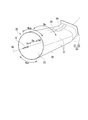
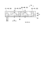
- the transition piece 20 has a tubular shape extending in the axial direction Da, and defines the periphery of the combustion gas flow passage 21 through which the combustion gas G flows. The transition piece 20 is formed around the combustor axis Ac.
- the combustion gas flow passage 21 gradually narrows from one side to the other side in the axial direction Da. Accordingly, the cross-sectional area of the transition piece 20 in a cross section perpendicular to the combustor axis Ac gradually decreases from one side to the other side in the axial direction Da.
- the one side in the axial direction Da is referred to as the upstream side Su
- the other side in the axial direction Da is referred to as the downstream side Sd.
- the circumferential direction of the combustion gas flow channel 21, that is, the circumferential direction with respect to the combustor axis Ac is simply referred to as a circumferential direction Dc.
- the combustor 4 is disposed in the gas turbine casing 9 in a space in which the compressed air A compressed by the compressor 1 drifts. Therefore, a partial region of the circumferential direction Dc of the transition piece 20 forms a rotor side region Rcr facing the gas turbine rotor 8, and another partial region of the circumferential direction Dc of the transition piece 20 forms a gas turbine casing
- the vehicle interior side region Rcc is opposed to the inner peripheral surface of 9.
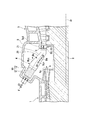
- the transition piece 20 of the present embodiment has a body portion 30 and an outlet flange portion 50 joined to the downstream side Sd of the body portion 30.
- the outlet flange portion 50 has a cylindrical shape, and includes a cylinder 51 defining a part of the combustion gas flow passage 21 and a flange 53 formed at the downstream end of the cylinder 51.
- the flange 53 is for connecting the transition piece 20 to the first stage stationary blade 5s1 of the turbine 5, as shown in FIG.
- the cylinder 51 and the flange 53 are integrally formed, for example, by casting or the like to form an outlet flange portion 50.
- a thermal barrier coating (TBC) layer (not shown) is applied to the inner circumferential surface of the tube 51.
- TBC thermal barrier coating
- a plurality of cooling passages 55 extending in the axial direction Da are formed.
- the inlet of the cooling passage 55 is formed on the outer peripheral surface of the cylinder 51, and the outlet of the cooling passage 55 is formed on the flange end surface of the flange 53.
- body part 30 curves several plywood 31, arranges several curved plywood 31 in the circumferential direction Dc, joins the ends of circumferential direction Dc of each plywood 31 by welding, and forms them in a cylinder shape. .
- two pieces of plywood 31 are arranged in the circumferential direction Dc, but, for example, three or more, for example, four pieces of plywood 31 are arranged in the circumferential direction Dc, It is also good.
- one piece of plywood 31 may be curved in a cylindrical shape, and ends of one piece of plywood 31 may be joined by welding.
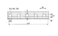
- the plywood 31 has an outer side plate 32 and an inner side plate 34, as shown in FIG. Of the pair of faces facing in opposite directions in the outer side plate 32, one face constitutes the outer circumferential face 32o, and the other face constitutes the joint face 32c. Further, of the pair of surfaces facing in opposite directions in the inner plate 34, one surface forms a bonding surface 34c, and the other surface forms an inner circumferential surface 34i.
- the bonding surface 32c of the outer side plate 32 is recessed toward the outer peripheral surface 32o, and a plurality of long grooves 33 elongated in a fixed direction are formed.
- the outer side plate 32 and the inner side plate 34 are joined to each other by joining surfaces 32 c and 34 c by brazing or the like to form a plywood 31. By the joining of the outer side plate 32 and the inner side plate 34, the opening of the long groove 33 formed in the outer side plate 32 is closed by the inner side plate 34, and the inside of the long groove 33 becomes the cooling passage 35.
- the inner circumferential surface 34i of the inner side plate 34 faces the inner circumferential side of the transition piece 20
- the outer circumferential surface 32o of the outer side plate 32 faces the outer circumferential side of the transition piece 20
- the cooling passage 35 extends.
- the direction is the axial direction Da of the transition piece 20, and as described above, the ends in the circumferential direction Dc are joined to each other.
- a cylinder is formed by joining a plurality of plywoods 31.
- a thermal barrier coating layer 36 is applied to the inner peripheral surface of the cylinder, that is, the inner peripheral surface 34i of the inner plate 34.
- the plywood 31 is formed with an inlet 35 i communicating with the cooling passage 35 from the outer peripheral surface 32 o of the outer side plate 32. Furthermore, an outlet 35 o communicating with the cooling passage 35 from the surface of the thermal barrier coating layer 36 is formed in the plywood 31.
- the combustor 4 is disposed in the gas turbine casing 9 in a space in which the compressed air A compressed by the compressor 1 drifts.
- the compressed air A in the gas turbine casing 9 flows into the cooling passage 35 of the body 30 from the inlet 35 i formed on the outer peripheral surface 32 o of the body 30 of the transition piece 20 as a cooling medium.
- the compressed air A flows from the cooling passage 35 through the outlet 35 o formed on the inner peripheral surface 34 i of the body 30 and flows out to the combustion gas flow path 21 formed on the inner peripheral side of the body 30.
- the compressed air A flows into the cooling passage 55 of the outlet flange portion 50 from the inlet formed on the outer peripheral surface of the outlet flange portion 50 of the transition piece 20.
- the compressed air A flows out of the cooling passage 55 through the outlet formed on the flange end surface of the outlet flange portion 50 to the outside.
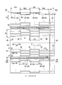
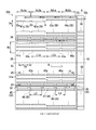
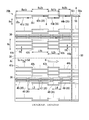
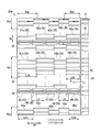
- FIG. 4 is a schematic development view of the cylindrical transition piece 20 developed on a plane and viewed from the inner peripheral surface 34 i side of the transition piece 20.
- the transition piece 20 is formed with a plurality of cooling passages 35 and 55 extending in the axial direction Da.
- the plurality of cooling passages 35 and 55 include a plurality of first upstream passages 41, a plurality of second upstream passages 42, a plurality of first downstream passages 43, a plurality of second downstream passages 44, and a plurality of first passages.
- a plurality of outlet flange passages 55 are formed in the outlet flange portion 50 of the transition piece 20.
- the outlet flange passage 55 forms a cooling passage 55 of the outlet flange portion 50.
- the passages 41 to 49 other than the outlet flange passage 55 are all formed in the body portion 30 of the transition piece 20.
- the other passages 41 to 49 form the cooling passage 35 of the body 30.
- the cross-sectional areas of the plurality of cooling passages 35 and 55 are the same at any position in the axial direction Da.
- the cross-sectional areas of the plurality of cooling passages 35 may differ from one another as described later.
- the cross-sectional areas of the plurality of cooling passages 55 may be different from one another.
- the plurality of first upstream passages 41 are formed in the circumferential direction Dc in the first upstream region Ru1 of the uppermost stream of the body portion 30 in the axial direction Da.
- the plurality of second upstream passages 42 are formed in the circumferential direction Dc in a second upstream region Ru2 of the downstream side Sd with respect to the first upstream region Ru1.
- the upstream portion of the second upstream region Ru2 overlaps the downstream portion of the first upstream region Ru1 in the axial direction Da. Therefore, the upstream side portion of the second upstream side passage 42 overlaps the downstream side portion of the first upstream side passage 41 in the axial direction Da, and is shifted in the circumferential direction Dc.
- the plurality of first downstream passages 43 are formed side by side in the circumferential direction Dc in the first downstream region Rd1 of the downstream side Sd with respect to the second upstream region Ru2.
- the upstream portion of the first downstream region Rd1 overlaps the downstream portion of the second upstream region Ru2 in the axial direction Da. Accordingly, the upstream side portion of the first downstream side passage 43 overlaps the downstream side portion of the second upstream side passage 42 in the axial direction Da, and is displaced in the circumferential direction Dc.
- the plurality of second downstream passages 44 are formed side by side in the circumferential direction Dc in the second downstream region Rd2 of the downstream side Sd with respect to the first downstream region Rd1.
- the second downstream region Rd2 is a region of the most downstream side Sd of the trunk portion 30.
- the upstream portion of the second downstream region Rd2 overlaps the downstream portion of the first downstream region Rd1 in the axial direction Da. Therefore, the upstream side portion of the second downstream side passage 44 overlaps the downstream side portion of the first downstream side passage 43 in the axial direction Da and is shifted in the circumferential direction Dc.
- a joint portion 38 extending in the axial direction Da is formed.
- the joint portion 38 is formed by joining the ends in the circumferential direction Dc of the plurality of plywoods 31 as described above with reference to FIG. 3.
- the first to fifth joint side passages 45 to 49 are all arranged along the joint portion 38.
- the first to fifth joint side passages 45 to 49 are closer to the joint 38 than the other passages 41 to 44 in the circumferential direction Dc.
- the first junction side passage 45, the second junction side passage 46, the third junction side passage 47, the fourth junction side passage 48, and the fifth junction side passage 49 are, in this order, the downstream side from the upstream side Su of the body portion 30. It is arranged side by side toward Sd.
- the length of the axial direction Da of the first upstream passage 41 and the length of the axial direction Da of the second upstream passage 42 are both L1.
- the passage length of the first downstream passage 43 and the passage length of the second downstream passage 44 are both L2.
- the passage length L1 and the passage length L2 are the same. Therefore, the passage length of the first upstream passage 41, the passage length of the second upstream passage 42, the passage length of the first downstream passage 43, and the passage lengths of the second downstream passage 44 are the same as each other. It is a length.
- each of the first joint passage 45, the second joint passage 46, and the third joint passage 47 is L3. Further, the lengths of the fourth joint side passage 48 and the fifth joint side passage 49 disposed downstream of the joint side passages 45 to 47 are both L4.
- the passage length L3 is shorter than the passage lengths L1 and L2. Further, the passage length L4 is shorter than the passage length L3. Therefore, the passage lengths L3 and L4 of the joint side passages 45 to 49 are all shorter than the passage lengths of any of the adjacent passages 41 to 44 in the circumferential direction Dc.
- each of the cooling passages 35 formed in the body portion 30 an inlet 35i is formed at the downstream end of the cooling passage 35, and an outlet 35o is formed at the upstream end of the cooling passage 35. Therefore, compressed air A flows from the downstream side Sd of the combustor 4 to the upstream side Su in each of the cooling passages 35 formed in the body portion 30. Therefore, the air in each cooling passage 35 flows in the opposite direction to the combustion gas G flowing through the combustion gas passage 21.
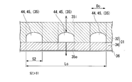
- the area of the first upstream passage 41 and the second upstream passage 42 in a cross section perpendicular to the axial direction Da is S1 as shown in FIG.
- path be channel
- the number of first upstream passages 41 and the number of second upstream passages 42 arranged in the circumferential region of the unit circumferential length Lc are the same.
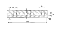
- the cross-sectional areas of the first downstream passage 43 and the second downstream passage 44 are both S2 as shown in FIG.
- the passage area S2 is larger than the passage cross-sectional area S1.
- the number of first downstream passages 43 and the number of second downstream passages 44 arranged in the circumferential region of the unit circumferential length Lc are the same.
- the total cross-sectional area per unit circumferential length Lc of the plurality of first downstream passages 43 disposed in the partial circumferential region Rc and in the first downstream region Rd1 is The total cross-sectional area per unit circumferential length Lc of the plurality of first upstream side passages 41 arranged in the same circumferential direction region Rc and in the first upstream side region Ru1 is larger. Similarly, the total cross-sectional area per unit circumferential length Lc of the plurality of first downstream passages 43 disposed in the same circumferential region Rc and in the first downstream region Rd1 is the same circumferential region Rc.
- the total cross-sectional area per unit circumferential length Lc of the plurality of second upstream passages 42 disposed inside and in the second upstream region Ru2 is larger.
- the total cross-sectional area per unit circumferential length Lc of the plurality of second downstream passages 44 disposed in the same circumferential region Rc and in the second downstream region Rd2 is the same as in the same circumferential region Rc.
- the total cross-sectional area per unit circumferential length Lc of the plurality of second downstream passages 44 disposed in the same circumferential region Rc and in the second downstream region Rd2 is the same circumferential region Rc.
- the total cross-sectional area per unit circumferential length Lc of the plurality of second upstream passages 42 disposed inside and in the second upstream region Ru2 is larger.
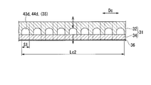
- the passage cross-sectional area of each of the first to fifth connection side passages 45 to 49 is S3.
- the passage cross-sectional area S3 is larger than the passage cross-sectional areas S1 and S2.
- the heights of the respective passages are made constant, and the widths of the respective passages are changed to change the passage sectional areas of the respective passages.
- the width of each passage constant and changing the height of each passage, the passage cross-sectional area between the passages may be changed.
- an inlet 55 i is formed at the upstream end of the outlet flange passage 55, and the downstream of the outlet flange passage 55
- An outlet 55o is formed at the end.
- the outlet 55 o is opened at the downstream end surface of the flange 53 as described above. Therefore, the air in each of the outlet flange passages 55 formed in the outlet flange portion 50 flows from the upstream side Su to the downstream side Sd of the combustor 4 in the same manner as the combustion gas G Flow out.
- Fuel F is injected into the transition piece 20 together with the compressed air A from the plurality of burners 11 of the fuel supplier.
- the fuel F burns in the compressed air A.
- High temperature combustion gas G is generated by the combustion of the fuel F.
- the combustion gas G flows in the transition piece 20 to the downstream side Sd and flows into the combustion gas flow path of the turbine 5.
- the combustion of the fuel proceeds toward the downstream side Sd.
- the downstream side Sd becomes hotter than the upstream side Su.
- the transition piece 20 is exposed to the hot gas at the downstream side Sd than at the upstream side Su.
- the combustion gas flow path 21 in the transition piece 20 gradually narrows from the upstream side Su to the downstream side Sd.
- the gas flow rate is higher in the downstream side Sd than in the upstream side Su. Therefore, in the transition piece 20, the heat transfer coefficient with the gas is higher in the downstream side Sd than in the upstream side Su.
- the downstream side Sd is exposed to a higher temperature gas than the upstream side Su, and the downstream side Sd has a higher heat transfer coefficient with the gas than the upstream side Su.
- the downstream side Sd is easier to heat than the upstream side Su.
- air is allowed to flow from the downstream side Sd of the combustor 4 to the upstream side Su in the plurality of cooling passages 35 of the body portion 30, and the downstream side Sd in each cooling passage 35 is efficiently made. Cool down.
- the cross-sectional area is made larger than the total cross-sectional area per unit circumferential length Lc of the plurality of upstream side passages 41 and 42 arranged in the same circumferential direction region Rc and in the upstream side region Ru.
- the flow rate of the air flowing through the downstream passages 43, 44 is larger than the flow rate of the air flowing through the upstream passages 41, 42, and the downstream region Rd is more than the cooling capacity of the upstream region Ru.
- the cooling capacity of the upstream region Ru is suppressed by reducing the flow rate of the air flowing through the upstream passages 41 and 42 in the upstream region Ru which is not heated more than the downstream region Rd.
- the passage cross-sectional area S3 of the joint side passages 45 to 49 which is the cooling passage 35 closest to the joint portion 38 in the circumferential direction Dc is adjacent to the joint side passages 45 to 49 in the circumferential direction Dc. It is made larger than the passage cross-sectional area S1 or S2 of the cooling passages 41-44. Furthermore, in the present embodiment, as shown in FIG. 4, the passage lengths L3 and L4 of the joint side passages 45 to 49 which are the cooling passages 35 closest to the joint portion 38 in the circumferential direction Dc It is shorter than the passage lengths L1 and L2 of the other cooling passages 41 to 44 adjacent to 49 in the circumferential direction Dc.
- the cooling capacity of the joint side passages 45 to 49 is enhanced, and the other two cooling passages 41 to 44 are formed between the two cooling passages 45 to 49 in which the joint portion 38 is disposed. It can be cooled equally to each other.
- the temperature of the entire transition piece 20 becomes equal to or lower than a predetermined temperature, and the temperature can be equalized, and the durability of the transition piece 20 can be ensured. Furthermore, in the present embodiment, while increasing the flow rate of the cooling medium flowing through the cooling passage 35 in the region where the heating amount is large, the flow rate of the cooling medium flowing through the cooling passage 35 in the region where the heating amount is small is reduced. As a whole, therefore, the flow rate of the cooling medium can be reduced.
- the passage cross-sectional area of the first upstream passage 41 and the passage cross-sectional area of the second upstream passage 42 are the same.
- the passage cross-sectional area of the second upstream passage 42 may be larger than the passage cross-sectional area of the first upstream passage 41.
- the passage cross-sectional area of the first downstream side passage 43 and the passage cross-sectional area of the second downstream side passage 44 are the same.
- the passage cross-sectional area of the second downstream passage 44 may be larger than the passage cross-sectional area of the first downstream passage 43.
- the upstream side portion of the second upstream side passage 42 overlaps the downstream side portion of the first upstream side passage 41 in the axial direction Da.
- the upstream side portion of the first downstream side passage 43 overlaps the downstream side portion of the second upstream side passage 42 in the axial direction Da.
- the upstream side portion of the second downstream side passage 44 overlaps the downstream side portion of the first downstream side passage 43 in the axial direction Da.
- the cooling passages 41 to 44 may not overlap in the axial direction Da.
- the passage cross sectional area of the downstream side passages 43 and 44 is made larger than the passage cross sectional area of the upstream side passages 41 and 42.
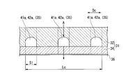
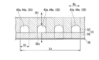
- the transition piece 20a of this embodiment as shown in FIG. 8, although the passage cross sectional area of the downstream side passages 43a and 44a and the passage cross sectional area of the upstream side passages 41a and 42a are the same, the unit circumferential length The number of downstream passages 43a and 44a per unit length Lc is greater than the number of upstream passages 41a and 42a per unit circumferential length Lc.
- the transition piece 20a of this embodiment is different from the first embodiment in the related point, and the other configuration is the same as the configuration of the first embodiment.
- the transition piece 20a of the present embodiment includes a plurality of first upstream passages 41a, a plurality of second upstream passages 42a, a plurality of first downstream passages 43a, and a plurality of first upstream passages 41a.
- a second downstream passage 44a, a plurality of first to fifth joint passages 45 to 49, and a plurality of outlet flange passages 55 are formed.
- the passage length of the first upstream passage 41a and the passage length of the second upstream passage 42a are both L1a.
- the passage length of the first downstream passage 43a and the passage length of the second downstream passage 44a are both L2a.
- the passage length L1a and the passage length L2a are the same.
- the passage cross-sectional areas of the first upstream passage 41a and the second upstream passage 42a are both S1 as shown in FIG. Further, as shown in FIG. 10, the passage cross-sectional areas of the first downstream passage 43a and the second downstream passage 44a are the same S1 as the passage cross-sectional areas of the first upstream passage 41a and the second upstream passage 42a. . However, the number of the first downstream side passage 43a and the second downstream side passage 44a per unit circumferential length Lc is the number of the first upstream side passage 41a and the second upstream side passage 42a per unit circumferential length Lc. More than.
- the unit circumferential length of the plurality of first downstream passages 43a disposed in the partial circumferential region Rc and in the first downstream region Rd1a The total cross-sectional area per height Lc is calculated from the total cross-sectional area per unit circumferential length Lc of the plurality of first upstream passages 41a disposed in the same circumferential direction region Rc and in the first upstream side region Ru1a. Too big.
- the total cross-sectional area per unit circumferential length Lc of the plurality of first downstream passages 43a disposed in the same circumferential region Rc and in the first downstream region Rd1a is the same circumferential region Rc.
- the total cross-sectional area per unit circumferential length Lc of the plurality of second upstream passages 42a disposed inside and in the second upstream region Ru2a is larger.
- the total cross-sectional area per unit circumferential length Lc of the plurality of second downstream passages 44a disposed in the same circumferential region Rc and in the second downstream region Rd2a is the same as in the same circumferential region Rc.
- the total cross-sectional area per unit circumferential length Lc of the plurality of second downstream passages 44a disposed in the same circumferential region Rc and in the second downstream region Rd2a is the same circumferential region Rc.
- the total cross-sectional area per unit circumferential length Lc of the plurality of second upstream passages 42a disposed inside and in the second upstream region Ru2a is larger.
- the transition piece is exposed to the gas at a higher temperature on the downstream side Sd than on the upstream side Su, and the heat transfer coefficient with the gas is higher on the downstream side Sd than on the upstream side Su.
- the downstream side Sd is easier to heat than the upstream side Su.
- the present embodiment by increasing the number of the downstream passages 43a and 44a per unit circumferential length Lc, a plurality of the passages disposed in a part of the circumferential region Rc and in the downstream region Rda
- the total cross-sectional area per unit circumferential length Lc of the downstream passages 43a and 44a is the unit circumference of the plurality of upstream passages 41a and 42a disposed in the same circumferential region Rc and in the upstream region Rua. It is larger than the total cross-sectional area per direction length Lc.
- the total flow rate of air flowing in the downstream passages 43a and 44a in the downstream region Rda is larger than the total flow rate of the air flowing in the upstream passages 41a and 42a in the upstream region Rua.
- the cooling capacity of the downstream area Rda is higher than the cooling capacity of the upstream area Rua.
- the cooling capacity of the upstream region Ru is suppressed by reducing the total flow rate of air flowing through the upstream passages 41a and 42a in the upstream region Rua which is not heated more than the downstream region Rda. .
- the durability of the transition piece 20a can be secured, and the flow rate of the cooling medium can be suppressed.
- the number of first upstream passages 41 a per unit circumferential length Lc is the same as the number of second upstream passages 42 a.
- the number of second upstream passages 42 a per unit circumferential length Lc may be greater than the number of first upstream passages 41 a.
- the number of first downstream side passages 43a per unit circumferential length Lc and the number of second downstream side passages 44a are the same.
- the number of second downstream passages 44a per unit circumferential length Lc may be larger than the number of first downstream passages 43a.
- the passage cross-sectional areas of the first downstream passage 43a and the second downstream passage 44a are the same as in the first embodiment, and the passage cross sections of the first upstream passage 41a and the second upstream passage 42a are disconnected. It may be larger than the area.
- the passage cross sectional area of the downstream side passages 43 and 44 is made larger than the passage cross sectional area of the upstream side passages 41 and 42.
- the passage cross sectional area of the downstream side passages 43b and 44b and the passage cross sectional area of the upstream side passages 41b and 42b are the same, the passage lengths of the downstream side passages 43b and 44b are set. It is shorter than the passage length of the upstream side passages 41b and 42b.
- the transition piece 20b of this embodiment is different from the first embodiment in the related point, and the other configuration is the same as the configuration of the first embodiment.
- the transition piece 20b of the present embodiment includes a plurality of first upstream passages 41b, a plurality of second upstream passages 42b, a plurality of first downstream passages 43b, and a plurality of first upstream passages 41b.
- a second downstream side passage 44b, a plurality of first to fifth joint side passages 45 to 49, and a plurality of outlet flange passages 55 are formed.
- the passage length of the first upstream passage 41b and the passage length of the second upstream passage 42b are both L1b.
- the passage length of the first downstream passage 43b and the passage length of the second downstream passage 44b are both L2b.
- the passage length L2b is shorter than the passage length L1b.
- the passage lengths of the first joint passage 45, the second joint passage 46, and the third joint passage 47 are all L3. Further, the lengths of the fourth joint side passage 48 and the fifth joint side passage 49 disposed downstream of the joint side passages 45 to 47 are L4.
- the passage length L3 is shorter than the passage length L1b.
- the passage length L4 is shorter than the passage length L3 and the passage length L2b. Therefore, the passage lengths of the joint side passages 45 to 49 are all shorter than the passage lengths of any adjacent passages in the circumferential direction Dc.
- the passage length L3 may be longer than the passage length L2b or shorter than the passage length L2b as long as the passage length L3 is shorter than the passage length L1b.
- the passage cross-sectional areas of the first upstream passage 41b, the second upstream passage 42b, the first downstream passage 43b, and the second downstream passage 44b are all S1. Further, the number of first downstream side passages 43b per unit circumferential length Lc, the number of second downstream side passages 44b, the number of first upstream side passages 41b, and the number of second upstream side passages 42b Similar to the embodiment, they are the same.
- the ratio of the passage cross-sectional area S1 to the passage length L2b of the downstream passages 43b and 44b disposed in the partial circumferential region Rc and in the downstream regions Rd1b and Rd2b (S1 / 1 L2b) is larger than the ratio (S1 / L1b) of the passage cross-sectional area S1 to the passage length L1b of the upstream passages 41b and 42b disposed in the circumferential region Rc and in the upstream regions Ru1b and Ru2b Become.
- the transition piece is exposed to the higher temperature gas on the downstream side Sd than on the upstream side Su, and the heat transfer coefficient with the gas is higher on the downstream side Sd than on the upstream side Su
- the downstream side Sd is easier to heat than the upstream side Su.
- a cooling passage with a short passage length has a higher cooling capacity than a cooling passage with a long passage length. Therefore, in the present embodiment, the passage length L2b of the downstream passages 43b and 44b is shorter than the passage length L1b of the upstream passages 41b and 42b.
- the durability of the transition piece 20b can be secured, and the flow rate of the cooling medium can be suppressed.
- the ratio of the passage cross-sectional area S1 to the passage length L2b of the downstream passages 43b and 44b disposed in the partial circumferential region Rc and in the downstream regions Rd1b and Rd2b (S1 / 1
- a method is employed in which the passage length L2b of the downstream passages 43b and 44b is shorter than the passage length L1b of the upstream passages 41b and 42b.
- the downstream side regions Rd1b and Rd2b in a part of the circumferential region Rc It is possible to increase the ratio of the passage cross-sectional area to the passage length of the downstream side passages 43b and 44b disposed inside. Therefore, in the first embodiment, the ratio (S2 / L2) of the passage cross-sectional area S2 to the passage length L2 of the downstream passages 43 and 44 disposed in the circumferential region Rc and in the downstream region Rd. Is larger than the ratio (S1 / L1) of the passage cross-sectional area S1 to the passage length L1 of the upstream passages 41 and 42 disposed in the circumferential region Rc and in the upstream region Ru It can be said.
- the passage length of the first upstream passage 41 b and the passage length of the second upstream passage 42 b are the same.
- the passage length of the second upstream passage 42b may be shorter than the passage length of the first upstream passage 41b.
- the passage length of the first downstream side passage 43b and the passage length of the second downstream side passage 44b are the same.
- the passage length of the second downstream passage 44b may be shorter than the passage length of the first downstream passage 43b.
- the passage cross-sectional areas of the first downstream passage 43b and the second downstream passage 44b are the same as in the first embodiment, the passages of the first upstream passage 41b and the second upstream passage 42b. It may be larger than the cross sectional area. Also in this embodiment, the number of first downstream passages 43b and second downstream passages 44b is greater than the number of first upstream passages 41b and second upstream passages 42b, as in the second embodiment. You may
- the transition piece 20 includes the rotor side region Rcr facing the gas turbine rotor 8 and the vehicle compartment side region Rcc facing the inner circumferential surface of the gas turbine casing 9. There is. A discharge port 1o of the compressor 1 is present radially inside the transition piece 20 in the radial direction based on the rotation axis Ar of the gas turbine. For this reason, in the rotor side area Rcr of the transition piece 20, the compressed air A having a high flow velocity immediately after flowing out of the compressor 1 is directly blown. On the other hand, since the compressed air A stagnates outside the transition piece 20 in the radial direction, the flow velocity of the compressed air A is low.
- the heat transfer coefficient between the compressed air A present on the outer peripheral side of the transition piece 20 and the transition piece 20 is such that the rotor side region Rcr is high among the respective regions in the circumferential direction Dc in the transition piece 20, and the cabin side region Rcc goes down.
- the cooling effect of the transition piece 20 by the compressed air A present on the outer peripheral side of the transition piece 20 is such that the rotor side region Rcr is high and the vehicle compartment side region Rcc is among the respective regions in the circumferential direction Dc in the transition piece 20 It gets lower.
- the passage cross-sectional area of the cooling passage 35 in the vehicle compartment side region Rcc is larger than the passage cross-sectional area of the cooling passage 35 in the rotor side region Rcr.
- the transition piece 20c of this embodiment is different from the first embodiment in the related point, and the other configuration is the same as the configuration of the first embodiment. Therefore, in the present embodiment as well, basically the same effects as in the first embodiment can be obtained.
- the plurality of first upstream passages 41 and 41c, the plurality of second upstream passages 42 and 42c, and the plurality of first downstream passages 43, 43c, a plurality of second downstream passages 44, 44c, a plurality of first to fifth joint passages 45 to 49, and a plurality of outlet flange passages 55 are formed.
- first upstream passage 41, 41c a region including the rotor side region Rcr except the first upstream vehicle chamber side passage 41c existing in the vehicle chamber side region Rcc and the vehicle room side region Rcc.
- first upstream rotor side passage 41 present inside.
- second upstream passage 42, 42c in a region including the rotor side region Rcr except for the second upstream vehicle chamber side passage 42c existing in the vehicle chamber side region Rcc and the vehicle cabin side region Rcc.
- second upstream rotor side passage 42 present.
- first downstream side passages 43 and 43c in the region including the rotor side region Rcr except for the first downstream vehicle chamber side passage 43c existing in the vehicle chamber side region Rcc and the vehicle room side region Rcc.
- first downstream rotor side passage 43 there is a first downstream rotor side passage 43 present.
- second downstream passage 44, 44c in a region including the rotor side region Rcr except for the second downstream vehicle chamber side passage 44c existing in the vehicle chamber side region Rcc and the vehicle cabin side region Rcc.
- second downstream rotor side passage 44 present.
- the passage length of the first upstream cabin side passage 41c, the passage length of the first upstream rotor side passage 41, the passage length of the second upstream cabin side passage 42c, and the passage length of the second upstream rotor side passage 42 are As in the first embodiment, all are L1.
- the passage length of the first downstream cabin side passage 43c, the passage length of the first downstream rotor side passage 43, the passage length of the second downstream cabin side passage 44c, and the passage length of the second downstream rotor side passage 44 Are both L2. Also in this embodiment, the passage length L1 and the passage length L2 are the same.
- first upstream chamber side passages 41c, the number of first upstream rotor side passages 41, the number of second upstream chamber side passages 42c, and the number of second upstream rotor side passages 42 per unit circumferential length Lc.
- the numbers are identical to one another.
- the passage cross-sectional area of the first upstream rotor side passage 41 and the second upstream rotor side passage 42 is S1 similar to the passage cross-sectional area of the first upstream side passage 41 and the second upstream side passage 42 in the first embodiment.
- the passage cross-sectional area of the first downstream rotor side passage 43 and the second downstream rotor side passage 44 is S2 similarly to the passage cross-sectional area of the first downstream side passage 43 and the second downstream side passage 44 in the first embodiment. Therefore, the passage cross-sectional area S2 of the first downstream rotor side passage 43 and the second downstream rotor side passage 44 is larger than the passage cross-sectional area S1 of the first upstream rotor side passage 41 and the second upstream rotor side passage 42.
- the passage cross sectional area of the first upstream cabin side passage 41c and the second upstream cabin side passage 42c is S1a larger than the passage cross sectional area S1 of the first upstream rotor side passage 41 and the second upstream rotor side passage 42.
- the passage cross sectional area of the first downstream cabin side passage 43c and the second downstream cabin side passage 44c is S2a larger than the passage cross sectional area S2 of the first downstream rotor side passage 43 and the second downstream rotor side passage 44.
- the passage cross-sectional area S2a of the first downstream cabin side passage 43c and the second downstream cabin side passage 44c is larger than the passage cross-sectional area S1a of the first upstream cabin side passage 41c and the second upstream cabin side passage 42c.
- the passage cross sectional area S1a of the first upstream cabin side passage 41c and the second upstream cabin side passage 42c is larger than the passage cross sectional area S1 of the first upstream rotor side passage 41 and the second upstream rotor side passage 42, and If it is smaller than the passage cross sectional area S2a of the first downstream cabin side passage 43c and the second downstream cabin side passage 44c, even if it is larger than the passage cross sectional area S2 of the first downstream rotor side passage 43 and the second downstream rotor side passage 44 , May be small.
- the total cross-sectional area per direction length Lc is the total cross-section per unit circumferential length Lc of the plurality of first downstream rotor side passages 43 disposed in the first downstream side region Rd1 and in the rotor side region Rcr. Larger than the area.
- the unit circumferential length Lc of the plurality of second downstream vehicle compartment side passages 44c disposed in the second downstream region Rd2 which is a partial region of the axial direction Da and in the vehicle compartment side region Rcc The total cross-sectional area of the hit is larger than the total cross-sectional area per unit circumferential length Lc of the plurality of second downstream rotor side passages 44 disposed in the second downstream side region Rd2 and in the rotor side region Rcr.
- the total cross sectional area per direction length Lc is the total cross section per unit circumferential length Lc of the plurality of first upstream rotor side passages 41 arranged in the first upstream side area Ru1 and in the rotor side area Rcr. Larger than the area.
- the unit circumferential length Lc of the plurality of second upstream vehicle compartment side passages 42c disposed in the second upstream side region Ru2 which is a partial region of the axial direction Da and in the vehicle compartment side region Rcc
- the total cross-sectional area of the hit is larger than the total cross-sectional area per unit circumferential length Lc of the plurality of second upstream rotor side passages 42 disposed in the second upstream side region Ru2 and in the rotor side region Rcr. .
- the flow rate of the air flowing through the cooling passage 35 in the vehicle compartment side region Rcc is larger than the flow rate of the air flowing through the cooling passage 35 in the rotor side region Rcr.
- the cooling capacity of the vehicle compartment side area Rcc is higher than the capacity. Therefore, in the present embodiment, the durability of the transition piece 20c can be further improved and the flow rate of the cooling medium can be suppressed as compared with the first embodiment.
- the passage cross-sectional area of the cooling passage 35 in the vehicle compartment side region Rcc is larger than the passage cross-sectional area of the cooling passage 35 in the rotor side region Rcr.
- the unit circumferential direction length The number of cooling passages 35 in the vehicle compartment side region Rcc per unit length Lc is greater than the number of cooling passages 35 in the rotor side region Rcr per unit circumferential length Lc.
- the plurality of first upstream cabin side passages 41d, the plurality of first upstream rotor side passages 41a, and the plurality of second upstream cabin sides The passage 42d, the plurality of second upstream rotor side passages 42a, the plurality of first downstream cabin side passages 43d, the plurality of first downstream rotor side passages 43a, the plurality of second downstream cabin side passages 44d, the plurality of second downstream sides
- a rotor side passage 44a, a plurality of first to fifth joint side passages 45 to 49, and a plurality of outlet flange passages 55 are formed.
- the passage length of the first upstream cabin side passage 41d, the passage length of the first upstream rotor side passage 41a, the passage length of the second upstream cabin side passage 42d, and the passage length of the second upstream rotor side passage 42a are All are L1a similarly to 2nd embodiment. Further, the passage length of the first downstream cabin side passage 43d, the passage length of the first downstream rotor side passage 43a, the passage length of the second downstream cabin side passage 44d, and the passage length of the second downstream rotor side passage 44a The length is L2a as in the second embodiment. Also in the present embodiment, as in the second embodiment, the passage length L1a and the passage length L2a are the same.
- the passage cross sectional area of the first downstream cabin side passage 43d, the passage cross sectional area of the first downstream rotor side passage 43a, the passage cross sectional area of the second downstream chamber side passage 44d, and the passage cross sectional area of the second downstream rotor side passage 44a As shown in FIGS. 14 to 17, all are S1.
- the number of first downstream rotor side passages 43a and second downstream rotor side passages 44a per unit circumferential length Lc2 is the first upstream rotor side passage per unit circumferential length Lc2. 41a and the number of second upstream rotor side passages 42a (see FIGS. 14 and 16). Further, the number of the first downstream vehicle chamber side passage 43d and the second downstream vehicle chamber side passage 44d per unit circumferential direction length Lc2 is the first upstream vehicle chamber side passage 41d and the second passage per unit circumferential direction length Lc. The number is larger than the number of the upstream cabin side passages 42d (see FIGS. 15 and 17).
- the number of the first upstream chamber side passage 41d and the second upstream chamber side passage 42d per unit circumferential length Lc is the first upstream rotor side passage per unit circumferential length Lc. More than the number 41a and the second upstream rotor side passage 42a (see FIGS. 14 and 15). Further, the number of the first downstream casing side passage 43d and the second downstream casing side passage 44d per unit circumferential length Lc is the first downstream rotor side passage 43a and the second downstream per unit circumferential length Lc. More than the number of rotor side passages 44a (see FIGS. 16 and 17).
- the unit circumferential length of the plurality of first downstream vehicle compartment side passages 43d arranged in the first downstream region Rd1a and in the vehicle compartment side region Rcc The total cross-sectional area per unit length Lc2 is the total cross-sectional area per unit circumferential length Lc2 of the plurality of first downstream rotor side passages 43a disposed in the first downstream side region Rd1a and in the rotor side region Rcr. Too big.
- the total cross-sectional area per unit circumferential length Lc2 of the plurality of second downstream cabin side passages 44d disposed in the second downstream side region Rd2a and in the cabin side region Rcc is the second downstream side.
- the total cross-sectional area per unit circumferential length Lc2 of the plurality of second downstream rotor side passages 44a disposed in the side region Rd2a and in the rotor side region Rcr is larger.
- the total cross-sectional area per unit circumferential length Lc2 of the plurality of first upstream vehicle compartment side passages 41d disposed in the first upstream side region Ru1a and in the vehicle compartment side region Rcc is The total cross-sectional area per unit circumferential length Lc2 of the plurality of first upstream rotor side passages 41a disposed in the first upstream side region Ru1a and in the rotor side region Rcr is larger.
- the total cross-sectional area per unit circumferential length Lc2 of the plurality of second upstream vehicle compartment side passages 42d disposed in the second upstream side region Ru2a and in the vehicle compartment side region Rcc is the second upstream
- the total cross-sectional area per unit circumferential length Lc of the plurality of second upstream rotor side passages 42a disposed in the side region Ru2a and in the rotor side region Rcr is larger.
- the flow rate of air flowing in the cooling passage 35 in the vehicle compartment side region Rcr is greater than the flow rate of air flowing in the cooling passage 35 in the rotor side region Rcr.
- the cooling capacity of the vehicle compartment side area Rcc can be higher than the cooling capacity of the rotor side area Rcr.
- the passage cross-sectional area of the cooling passage 35 in the vehicle compartment side region Rcc is larger than the passage cross-sectional area of the cooling passage 35 in the rotor side region Rcr.
- the passage cross sectional area of the cooling passage 35 in the vehicle compartment side region Rcc and the passage cross sectional area of the cooling passage 35 in the rotor side region Rcr are the same.
- the passage length of the cooling passage 35 in Rcc is made shorter than the passage length of the cooling passage 35 in the rotor side region Rcr.
- the plurality of first upstream vehicle chamber side passages 41e, the plurality of first upstream rotor side passages 41b, and the plurality of second upstream vehicle chamber sides A passage 42e, a plurality of second upstream rotor side passages 42b, a plurality of first downstream cabin side passages 43e, a plurality of first downstream rotor side passages 43b, a plurality of second downstream cabin side passages 44e, a plurality of second downstream sides A rotor side passage 44b, a plurality of first to fifth joint side passages 45 to 49, and a plurality of outlet flange passages 55 are formed.
- a plurality of third downstream cabin side passages 45e are further formed in the transition piece 20e of the present embodiment.
- the third downstream cabin side passage 45e is disposed in the second downstream cabin side passage 44e.
- the passage length of the first upstream rotor side passage 41b and the passage length of the second upstream rotor side passage 42b are both L1b, as in the third embodiment.
- the passage length of the first downstream rotor side passage 43b and the passage length of the second downstream rotor side passage 44b are both L2b.
- the passage length L2b is shorter than the passage length L1b.
- the passage length of the first upstream cabin side passage 41e and the passage length of the second upstream cabin side passage 42e are both L1 c.
- the passage length of the first downstream cabin side passage 43e, the passage length of the second downstream cabin side passage 44e, and the passage length of the third downstream cabin side passage 45e are all L2c.
- the passage length L2c is shorter than the passage length L1c. Further, the passage length L1c is shorter than the passage length L1b. Further, the passage length L2c is shorter than the passage length L2b. The passage length L1c may be longer or shorter than the passage length L2b as long as the passage length L1c is shorter than the passage length L1b.
- the passage cross-sectional area of the third downstream cabin side passage 45e is S1 (see FIGS. 5 and 11).
- first upstream rotor side passages 41b per unit circumferential length Lc the number of second upstream rotor side passages 42b, the number of first upstream vehicle room side passages 41e, and the number of second upstream vehicle room side passages 42e.
- the number of passages 45e is the same as each other as in the third embodiment.
- the ratio (S1 / L2b) is based on the ratio (S1 / L1b) of the passage cross-sectional area S1 to the passage length L1b of the upstream rotor side passages 41b and 42b disposed in the rotor side region Rcr and in the upstream region Rub. Will also grow.
- passage cross-sectional area S1 with respect to passage length L2c of downstream casing side passages 43e, 44e, 45e disposed in casing side region Rcc which is a part of the other circumferential region and in downstream region Rdb.
- the ratio (S1 / L2c) is the ratio of the passage cross-sectional area S1 to the passage length L1c of the upstream vehicle-chamber-side passages 41e and 42e disposed in the vehicle-chamber-side region Rcc and the upstream-side region Rub (S1 / L2c). It becomes larger than L1c).
- the passage cross-sectional area with respect to the passage length L1c of the upstream vehicle chamber side passages 41e and 42e disposed in the upstream region Rub which is a part of the axial region, and in the vehicle cabin side region Rcc.
- the ratio S1 (S1 / L1c) is the ratio of the passage cross-sectional area S1 to the passage length L1b of the upstream rotor side passages 41b and 42b disposed in the upstream region Rub and the rotor side region Rcr (S1 / L1b It becomes bigger than).
- the ratio of the passage cross-sectional area S1 to the passage length L2c of the downstream casing side passages 43e, 44e, 45e arranged in the downstream region Rdb which is a part of the axial direction region and in the casing side region Rcc (S1 / L2c) is more than the ratio (S1 / L2b) of the passage cross-sectional area S1 to the passage length L2b of the downstream rotor side passages 43b and 44b arranged in the downstream side region Rd and in the rotor side region Rcr. growing.
- the cooling capacity of the downstream side region Rd by the compressed air A can be enhanced. Furthermore, in the present embodiment, as in the fourth and fifth embodiments, it is possible to enhance the cooling capacity of the vehicle compartment side region Rcc by the compressed air A.
- the vehicle compartment side region A method is employed in which the passage length L1c of the cooling passage 35 in Rcc is shorter than the passage length L1b of the cooling passage 35 in the rotor side region Rcr.
- the ratio of the passage cross-sectional area to the passage length of the cooling passage 35 disposed in the side region Rcc can be increased. Therefore, in the fourth embodiment, the ratio of the passage cross-sectional area to the passage length of the cooling passage 35 disposed in a part of the axial region and in the vehicle compartment side region Rcc is in the coaxial direction region and the rotor It can be said that the ratio of the passage cross sectional area to the passage length of the cooling passage 35 disposed in the side region Rcr is larger.
- the first upstream cabin side passage 41c, the second upstream cabin side passage 42c, the first downstream cabin side passage 43c, and the second downstream cabin side passage 44c in the fourth embodiment the first upstream of the fifth embodiment
- the passenger compartment side passage 41d, the second upstream passenger room side passage 42d, the first downstream passenger room side passage 43d, and the second downstream passenger room side passage 44d may be employed.
- the first upstream cabin side passage 41c, the second upstream cabin side passage 42c, the first downstream cabin side passage 43c, and the second downstream cabin side passage 44c in the fourth embodiment are the sixth embodiment of the present invention.
- the first upstream compartment side passage 41e, the second upstream compartment side passage 42e, the first downstream compartment side passage 43e, the second downstream compartment side passage 44e, and the third downstream compartment side passage 45e may be employed.
- first upstream cabin side passage 41d, the second upstream cabin side passage 42d, the first downstream cabin side passage 43d, and the second downstream cabin side passage 44d in the fifth embodiment of the fourth embodiment The first upstream compartment side passage 41c, the second upstream compartment side passage 42c, the first downstream compartment side passage 43c, and the second downstream compartment side passage 44c may be employed.
- first upstream cabin side passage 41d, the second upstream cabin side passage 42d, the first downstream cabin side passage 43d, and the second downstream cabin side passage 44d in the fifth embodiment are used.
- the first upstream compartment side passage 41e, the second upstream compartment side passage 42e, the first downstream compartment side passage 43e, the second downstream compartment side passage 44e, and the third downstream compartment side passage 45e may be employed.
- the first upstream cabin side passage 41e, the second upstream cabin side passage 42e, the first downstream cabin side passage 43e, the second downstream cabin side passage 44e, and the third downstream cabin side passage The first upstream cabin side passage 41c, the second upstream cabin side passage 42c, the first downstream cabin side passage 43c, and the second downstream cabin side passage 44c of the fourth embodiment may be adopted as 45e.
- the first upstream cabin side passage 41e, the second upstream cabin side passage 42e, the first downstream cabin side passage 43e, the second downstream cabin side passage 44e, and the third downstream cabin side passage The first upstream cabin side passage 41d, the second upstream cabin side passage 42d, the first downstream cabin side passage 43d, and the second downstream cabin side passage 44d of the fifth embodiment may be adopted as 45e.
- the inlet 35i is formed at the downstream end of the cooling passage 35 and the outlet 35o is formed at the upstream end of the cooling passage 35 in all the cooling passages 35 of the body portion 30.
- an inlet is provided at the upstream end of the cooling passage 35 for a part of the cooling passage 35 of the body portion 30.
- the outlet may be formed at the downstream end of the cooling passage 35.
- all the cooling passages 35 and 55 have the same cross-sectional area at any position in the axial direction Da.
- the cross-sectional area of any of the cooling passages may change in accordance with the positional change in the axial direction Da.
- the body portion 30 is formed of the plywood 31 having the outer side plate 32 and the inner side plate 34.
- the body portion 30 may not be formed of the plywood 31 but may be formed of a veneer.
- the flow rate of the cooling medium can be suppressed while maintaining the durability of the transition piece.
Landscapes
- Engineering & Computer Science (AREA)
- Mechanical Engineering (AREA)
- General Engineering & Computer Science (AREA)
- Chemical & Material Sciences (AREA)
- Combustion & Propulsion (AREA)
- Turbine Rotor Nozzle Sealing (AREA)
Priority Applications (5)
| Application Number | Priority Date | Filing Date | Title |
|---|---|---|---|
| US15/544,384 US20170370235A1 (en) | 2015-01-30 | 2016-01-25 | Transition piece, combustor provided with same, and gas turbine provided with combustor |
| CN201680006588.9A CN107208555B (zh) | 2015-01-30 | 2016-01-25 | 过渡连接件、具备该过渡连接件的燃烧器以及具备燃烧器的燃气轮机 |
| KR1020177019601A KR102001746B1 (ko) | 2015-01-30 | 2016-01-25 | 트렌지션 피스, 이를 구비하는 연소기, 및 연소기를 구비하는 가스 터빈 |
| EP16743297.0A EP3252287B1 (en) | 2015-01-30 | 2016-01-25 | Transition piece, combustor provided with same and gas turbine provided with such a combustor |
| US17/140,694 US11525364B2 (en) | 2015-01-30 | 2021-01-04 | Transition piece, combustor provided with same, and gas turbine provided with combustor |
Applications Claiming Priority (2)
| Application Number | Priority Date | Filing Date | Title |
|---|---|---|---|
| JP2015017840A JP6476516B2 (ja) | 2015-01-30 | 2015-01-30 | トランジションピース、これを備える燃焼器、及び燃焼器を備えるガスタービン |
| JP2015-017840 | 2015-01-30 |
Related Child Applications (2)
| Application Number | Title | Priority Date | Filing Date |
|---|---|---|---|
| US15/544,384 A-371-Of-International US20170370235A1 (en) | 2015-01-30 | 2016-01-25 | Transition piece, combustor provided with same, and gas turbine provided with combustor |
| US17/140,694 Division US11525364B2 (en) | 2015-01-30 | 2021-01-04 | Transition piece, combustor provided with same, and gas turbine provided with combustor |
Publications (1)
| Publication Number | Publication Date |
|---|---|
| WO2016121694A1 true WO2016121694A1 (ja) | 2016-08-04 |
Family
ID=56543307
Family Applications (1)
| Application Number | Title | Priority Date | Filing Date |
|---|---|---|---|
| PCT/JP2016/052021 Ceased WO2016121694A1 (ja) | 2015-01-30 | 2016-01-25 | トランジションピース、これを備える燃焼器、及び燃焼器を備えるガスタービン |
Country Status (7)
| Country | Link |
|---|---|
| US (2) | US20170370235A1 (enExample) |
| EP (1) | EP3252287B1 (enExample) |
| JP (1) | JP6476516B2 (enExample) |
| KR (1) | KR102001746B1 (enExample) |
| CN (1) | CN107208555B (enExample) |
| TW (1) | TWI619909B (enExample) |
| WO (1) | WO2016121694A1 (enExample) |
Families Citing this family (9)
| Publication number | Priority date | Publication date | Assignee | Title |
|---|---|---|---|---|
| US10352244B2 (en) * | 2014-04-25 | 2019-07-16 | Mitsubishi Hitachi Power Systems, Ltd. | Combustor cooling structure |
| DE112016005084B4 (de) | 2015-11-05 | 2022-09-22 | Mitsubishi Heavy Industries, Ltd. | Verbrennungszylinder, Gasturbinenbrennkammer und Gasturbine |
| WO2018021993A1 (en) * | 2016-07-25 | 2018-02-01 | Siemens Aktiengesellschaft | Cooling features for a gas turbine engine |
| US10890328B2 (en) * | 2018-11-29 | 2021-01-12 | DOOSAN Heavy Industries Construction Co., LTD | Fin-pin flow guide for efficient transition piece cooling |
| CN115461532B (zh) * | 2020-07-20 | 2025-09-12 | 三菱重工业株式会社 | 过渡连接件、具备过渡连接件的燃烧器、燃气涡轮机及燃气涡轮机设备 |
| JP7370364B2 (ja) | 2021-09-30 | 2023-10-27 | 三菱重工業株式会社 | トランジションピース、燃焼器及びガスタービンエンジン |
| JP7326399B2 (ja) * | 2021-09-30 | 2023-08-15 | 三菱重工業株式会社 | トランジションピース、燃焼器及びガスタービンエンジン |
| EP4177522B1 (en) * | 2021-11-04 | 2024-06-26 | Rolls-Royce plc | Combustor arrangement |
| JP2023166152A (ja) * | 2022-05-09 | 2023-11-21 | 三菱重工業株式会社 | 燃焼器用筒、燃焼器、及びガスタービン |
Citations (6)
| Publication number | Priority date | Publication date | Assignee | Title |
|---|---|---|---|---|
| JPH1082527A (ja) * | 1996-09-05 | 1998-03-31 | Toshiba Corp | ガスタービン燃焼器 |
| US20060130484A1 (en) * | 2004-12-16 | 2006-06-22 | Siemens Westinghouse Power Corporation | Cooled gas turbine transition duct |
| JP2008274774A (ja) * | 2007-04-25 | 2008-11-13 | Mitsubishi Heavy Ind Ltd | ガスタービン燃焼器およびガスタービン |
| JP2010261318A (ja) * | 2009-04-30 | 2010-11-18 | Mitsubishi Heavy Ind Ltd | 板状体の製造方法、板状体、ガスタービン燃焼器およびガスタービン |
| JP2012077660A (ja) * | 2010-09-30 | 2012-04-19 | Mitsubishi Heavy Ind Ltd | 回収式空気冷却ガスタービン燃焼器冷却構造 |
| US20160047312A1 (en) * | 2014-08-15 | 2016-02-18 | Siemens Aktiengesellschaft | Gas turbine system |
Family Cites Families (10)
| Publication number | Priority date | Publication date | Assignee | Title |
|---|---|---|---|---|
| JPS62150543A (ja) | 1985-12-24 | 1987-07-04 | Matsushita Electric Ind Co Ltd | 再生装置 |
| JP2745694B2 (ja) | 1989-06-27 | 1998-04-28 | 日本電気株式会社 | 双方向バス伝送方式 |
| JP3846169B2 (ja) * | 2000-09-14 | 2006-11-15 | 株式会社日立製作所 | ガスタービンの補修方法 |
| JP3993484B2 (ja) | 2002-07-15 | 2007-10-17 | 三菱重工業株式会社 | 燃焼器冷却構造 |
| JP4823186B2 (ja) * | 2007-09-25 | 2011-11-24 | 三菱重工業株式会社 | ガスタービン燃焼器 |
| RU2530685C2 (ru) * | 2010-03-25 | 2014-10-10 | Дженерал Электрик Компани | Структуры ударного воздействия для систем охлаждения |
| JP5804872B2 (ja) | 2011-09-27 | 2015-11-04 | 三菱日立パワーシステムズ株式会社 | 燃焼器の尾筒、これを備えているガスタービン、及び尾筒の製造方法 |
| US8834154B2 (en) * | 2012-11-28 | 2014-09-16 | Mitsubishi Heavy Industries, Ltd. | Transition piece of combustor, and gas turbine having the same |
| JP6092597B2 (ja) * | 2012-11-30 | 2017-03-08 | 三菱日立パワーシステムズ株式会社 | ガスタービン燃焼器 |
| EP3002415A1 (en) * | 2014-09-30 | 2016-04-06 | Siemens Aktiengesellschaft | Turbomachine component, particularly a gas turbine engine component, with a cooled wall and a method of manufacturing |
-
2015
- 2015-01-30 JP JP2015017840A patent/JP6476516B2/ja active Active
-
2016
- 2016-01-25 EP EP16743297.0A patent/EP3252287B1/en active Active
- 2016-01-25 US US15/544,384 patent/US20170370235A1/en not_active Abandoned
- 2016-01-25 WO PCT/JP2016/052021 patent/WO2016121694A1/ja not_active Ceased
- 2016-01-25 KR KR1020177019601A patent/KR102001746B1/ko active Active
- 2016-01-25 CN CN201680006588.9A patent/CN107208555B/zh active Active
- 2016-01-26 TW TW105102347A patent/TWI619909B/zh active
-
2021
- 2021-01-04 US US17/140,694 patent/US11525364B2/en active Active
Patent Citations (6)
| Publication number | Priority date | Publication date | Assignee | Title |
|---|---|---|---|---|
| JPH1082527A (ja) * | 1996-09-05 | 1998-03-31 | Toshiba Corp | ガスタービン燃焼器 |
| US20060130484A1 (en) * | 2004-12-16 | 2006-06-22 | Siemens Westinghouse Power Corporation | Cooled gas turbine transition duct |
| JP2008274774A (ja) * | 2007-04-25 | 2008-11-13 | Mitsubishi Heavy Ind Ltd | ガスタービン燃焼器およびガスタービン |
| JP2010261318A (ja) * | 2009-04-30 | 2010-11-18 | Mitsubishi Heavy Ind Ltd | 板状体の製造方法、板状体、ガスタービン燃焼器およびガスタービン |
| JP2012077660A (ja) * | 2010-09-30 | 2012-04-19 | Mitsubishi Heavy Ind Ltd | 回収式空気冷却ガスタービン燃焼器冷却構造 |
| US20160047312A1 (en) * | 2014-08-15 | 2016-02-18 | Siemens Aktiengesellschaft | Gas turbine system |
Non-Patent Citations (1)
| Title |
|---|
| See also references of EP3252287A4 * |
Also Published As
| Publication number | Publication date |
|---|---|
| CN107208555A (zh) | 2017-09-26 |
| KR20170095346A (ko) | 2017-08-22 |
| JP6476516B2 (ja) | 2019-03-06 |
| KR102001746B1 (ko) | 2019-07-18 |
| US11525364B2 (en) | 2022-12-13 |
| EP3252287A4 (en) | 2018-04-11 |
| EP3252287A1 (en) | 2017-12-06 |
| EP3252287B1 (en) | 2019-07-17 |
| US20210123351A1 (en) | 2021-04-29 |
| CN107208555B (zh) | 2019-05-31 |
| JP2016142163A (ja) | 2016-08-08 |
| US20170370235A1 (en) | 2017-12-28 |
| TW201641893A (zh) | 2016-12-01 |
| TWI619909B (zh) | 2018-04-01 |
Similar Documents
| Publication | Publication Date | Title |
|---|---|---|
| JP6476516B2 (ja) | トランジションピース、これを備える燃焼器、及び燃焼器を備えるガスタービン | |
| US20210239402A1 (en) | Contoured wall heat exchanger | |
| EP3056816B1 (en) | Cooling structure for gas turbine engine component | |
| JP7051273B2 (ja) | タービン部品を冷却するための方法およびシステム | |
| CN104515146B (zh) | 内部冷却的过渡管后架 | |
| JP2013515893A (ja) | タービンステータの冷却方法および前記方法を実装する冷却システム | |
| US10267163B2 (en) | Airfoil turn caps in gas turbine engines | |
| JP2008531961A (ja) | ガスタービン・エンジン用の冷却移行ダクト | |
| JP2010203439A (ja) | 噴流冷却式単一構成缶型燃焼器 | |
| JP2016142163A5 (enExample) | ||
| US20160290643A1 (en) | Cooling a quench aperture body of a combustor wall | |
| JPWO2016136521A1 (ja) | 燃焼器用冷却パネル、これを備えるトランジションピース及び燃焼器、並びに燃焼器を備えるガスタービン | |
| JP5567180B1 (ja) | タービン翼の冷却構造 | |
| CN106801625A (zh) | 在护罩中具有出口通路的涡轮轮叶 | |
| IT202100000296A1 (it) | Motore a turbine con paletta avente un insieme di fossette | |
| JP2014009937A (ja) | ガスタービン用移行ダクト | |
| JP5507340B2 (ja) | ターボ機械圧縮機ホイール部材 | |
| JP2010249131A (ja) | 複合対流/しみ出し冷却一体形缶型燃焼器 | |
| JP6307137B2 (ja) | 共鳴音響ノイズを抑制するウィンデージシールドシステムおよび方法 | |
| US10590778B2 (en) | Engine component with non-uniform chevron pins | |
| CN113939645B (zh) | 用于燃气涡轮发动机的隔热罩 | |
| CN110388236A (zh) | 具备嵌件支持部的透平机静叶片 | |
| WO2019073584A1 (ja) | コンプレッサーハウジング及びこのコンプレッサーハウジングを備えるターボチャージャー | |
| CN107762564A (zh) | 带有多孔肋部的用于涡轮发动机的翼型件 | |
| RU2737270C1 (ru) | Компонент турбомашины с внутренним охлаждением |
Legal Events
| Date | Code | Title | Description |
|---|---|---|---|
| 121 | Ep: the epo has been informed by wipo that ep was designated in this application |
Ref document number: 16743297 Country of ref document: EP Kind code of ref document: A1 |
|
| REEP | Request for entry into the european phase |
Ref document number: 2016743297 Country of ref document: EP |
|
| ENP | Entry into the national phase |
Ref document number: 20177019601 Country of ref document: KR Kind code of ref document: A |
|
| WWE | Wipo information: entry into national phase |
Ref document number: 15544384 Country of ref document: US |
|
| NENP | Non-entry into the national phase |
Ref country code: DE |