WO2016121490A1 - Dispositif de mesure de rotondité - Google Patents
Dispositif de mesure de rotondité Download PDFInfo
- Publication number
- WO2016121490A1 WO2016121490A1 PCT/JP2016/050715 JP2016050715W WO2016121490A1 WO 2016121490 A1 WO2016121490 A1 WO 2016121490A1 JP 2016050715 W JP2016050715 W JP 2016050715W WO 2016121490 A1 WO2016121490 A1 WO 2016121490A1
- Authority
- WO
- WIPO (PCT)
- Prior art keywords
- arm
- detector
- radial
- radial direction
- workpiece
- Prior art date
Links
Images


Classifications
-
- G—PHYSICS
- G01—MEASURING; TESTING
- G01B—MEASURING LENGTH, THICKNESS OR SIMILAR LINEAR DIMENSIONS; MEASURING ANGLES; MEASURING AREAS; MEASURING IRREGULARITIES OF SURFACES OR CONTOURS
- G01B5/00—Measuring arrangements characterised by the use of mechanical techniques
- G01B5/28—Measuring arrangements characterised by the use of mechanical techniques for measuring roughness or irregularity of surfaces
- G01B5/285—Measuring arrangements characterised by the use of mechanical techniques for measuring roughness or irregularity of surfaces for controlling eveness
-
- G—PHYSICS
- G01—MEASURING; TESTING
- G01B—MEASURING LENGTH, THICKNESS OR SIMILAR LINEAR DIMENSIONS; MEASURING ANGLES; MEASURING AREAS; MEASURING IRREGULARITIES OF SURFACES OR CONTOURS
- G01B5/00—Measuring arrangements characterised by the use of mechanical techniques
- G01B5/20—Measuring arrangements characterised by the use of mechanical techniques for measuring contours or curvatures
- G01B5/201—Measuring arrangements characterised by the use of mechanical techniques for measuring contours or curvatures for measuring roundness
Definitions
- the present invention relates to a roundness measuring apparatus, and in particular, a perfect circle in which a probe tip is brought into contact with the surface of a workpiece rotatably installed on a table, and a displacement of the probe tip according to a rotation angle is detected by a detector. It relates to a degree measuring device.
- a conventional roundness measuring device has a radial movement arm that moves in a radial direction with respect to a workpiece having a cylindrical surface placed on a rotary table as in Patent Document 1, and is provided at the tip of the radial movement arm.
- a detector (measurement probe) is attached via a detector holder.
- the detector is arranged via the detector holder further on the tip side than the tip of the radial movement arm. For this reason, there is a space between the detector and the radial movement arm, and there is a disadvantage that the apparatus is enlarged accordingly.
- the present invention has been made in view of such circumstances, and an object of the present invention is to provide a roundness measuring device that can be miniaturized.
- a roundness measuring apparatus is a base and a mounting table that is provided on the base and mounts an object to be measured, along the vertical direction.
- a stage that can rotate around a rotation axis, a column that stands on the base and extends in the vertical direction, a carriage that is supported by the column so as to be movable in the vertical direction along the column, and a rotation of the stage
- a detector holder support mechanism which is a radial arm supported by the distal end portion of the turning arm and supports the detector holder so as to be movable in the radial direction via the radial arm extending in the radial direction.
- the larger the outer diameter of the cylindrical or columnar measurement object the narrower the distance between the detector holder (detector) and the swivel arm, and the measurement of the outer peripheral surface of the measurement object. Therefore, the interval between the column and the mounting table can be narrowed, and the apparatus can be miniaturized.
- the swivel arm on the stage side with respect to the column, compared to the case where a radial arm for moving the detector in the radial direction is provided on the carriage, it is on the opposite side of the stage with respect to the column.
- the protruding amount of the protruding radial arm can be reduced. Therefore, the measurement space required for the measurement can be reduced, and the size of the apparatus including the measurement space can be reduced.
- the detector holder support mechanism has a detector holder fixed to the distal end portion of the radial arm, and the distal end of the swivel arm is movable in the radial direction. It can be set as the aspect supported by the part.
- the radial arm includes a rack gear formed along the radial direction
- the swivel arm is a pinion gear that is manually rotated and is associated with the rack gear. It can be set as the aspect provided with the pinion gear to match.
- the detector holder support mechanism is configured such that the radial arm is fixed to the distal end portion of the turning arm, and the detector holder is supported so as to be movable along the radial arm. It can be set as the mode which was made.
- the roundness measuring device can be downsized.
- the perspective view which showed the whole structure of the roundness measuring apparatus based on this invention The perspective view which showed the upper end part of the radial direction movement arm and the turning arm Sectional view perpendicular to the radial direction of the upper end of the radial movement arm and swivel arm Front view of the roundness measuring device showing a state in which a probe is brought into contact with the upper outer peripheral surface of the workpiece
- Front view of the roundness measuring device showing a state in which a probe is brought into contact with the upper outer peripheral surface of the workpiece
- Front view of the roundness measuring device showing how the probe touches the inner peripheral surface of the workpiece
- FIG. 12 is a diagram comparing the measurement space in the known roundness measuring apparatus in FIG. 12 with the measurement space in the roundness measuring apparatus of the present embodiment in FIG. Simplified diagram showing another embodiment of detector holder support mechanism Front view of the roundness measuring device showing the contact of the probe with the upper surface of the flange part of the workpiece A perspective view of a roundness measuring apparatus showing a state in which a probe is brought into contact with the upper surface of the flange portion of the workpiece Front view of the roundness measuring device showing the contact point on the bottom surface of the workpiece flange A perspective view of a roundness measuring apparatus showing a state in which a probe is brought into contact with the lower surface of the flange portion of the workpiece
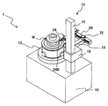
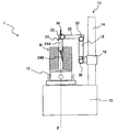
- FIG. 1 is a perspective view showing the entire configuration of a roundness measuring apparatus according to the present invention.
- the roundness measuring apparatus 1 shown in the figure includes a base 10 that supports the entire apparatus at the lower end, and a rotation axis ( ⁇ -axis) along the vertical direction (Z-axis direction) is formed on the upper surface of the base 10. )
- a stage 12 that is rotatable in the circumferential direction is provided.
- a columnar or cylindrical workpiece W that is a measurement object is placed on the upper surface of the stage 12. Further, the workpiece W is placed so that the central axis thereof is coaxial with the rotation axis of the mounting table 12.
- work W in the figure illustrates the workpiece
- a rotation drive unit (not shown) that includes a motor connected to the mounting table 12 and that rotationally drives the mounting table 12 is provided.
- the workpiece W placed on the stage 12 is rotated in the direction around the ⁇ axis together with the stage 12 by the rotation driving unit.
- stage 12 may be manually rotated. Further, the mounting table 12 may be movable in the direction perpendicular to the ⁇ axis and in the left-right direction and the front-rear direction orthogonal to each other by rotating the knob.
- a detector 24 (measurement probe) is supported on the upper surface side of the base 10 via a detector support mechanism 13 having a column 14, a carriage 16, a turning arm 18, a radial movement arm 20, and a detector holder 22.
- the detector 24 is provided, for example, in a measuring element 24B (stylus) extending in a rod shape from the lower end of the cylindrical detector main body 24A, and inside the detector main body 24A, and detects a displacement amount of the measuring element 24B by an operating transformer or the like. And a displacement detector (not shown) for outputting as an electrical signal.
- the measuring element 24B is supported by the detector main body 24A so that the axis line of the measuring element 24B can be displaced in a direction (displacement direction) perpendicular to the axis line in one plane, and one direction (attachment) of the displacement direction is attached. Is biased by a spring or the like.
- the detector support mechanism 13 will be described.
- a column 14 extending in the vertical direction is provided on the right side of the mounting table 12.
- the column 14 supports a carriage 16 that can move in the vertical direction along the column 14.
- the carriage 16 moves up and down by, for example, driving of a motor, but may be moved manually by rotating a knob or the like.
- the detector support mechanism 13 supports the detector 24 so that the position in the vertical direction can be changed by the moving mechanism of the carriage 16 in the vertical direction.
- One end (base end) of the swivel arm 18 is coupled to the carriage 16 so as to be pivotable around a swivel axis extending in the left-right direction on the left side of the column 14 (on the table 12 side).
- the swivel arm 18 is formed in a quadrangular prism shape, and by rotating the knob 30 to loosen the screw, the swivel arm 18 can be swung around the swivel axis to change the direction of the swivel arm 18.
- the left-right direction is a radial direction (R-axis direction) centered on the rotation axis ( ⁇ -axis) of the mounting table 12, that is, a direction (from the position of the turning axis in the carriage 16 toward the rotation axis of the mounting table 12 ( And the opposite direction) and the radial direction.
- the detector support mechanism 13 supports the detector 24 so that the turning angle around the turning axis along the radial direction can be changed by the turning mechanism of the turning arm 18.
- a radial movement arm 20 extending in the radial direction is supported at the distal end of the turning arm 18 so as to be movable in the radial direction.
- the radial movement arm 20 moves in a direction corresponding to the rotation direction by rotating the knob 32.
- the detector support mechanism 13 supports the position of the detector 24 in the radial direction so as to be changeable by the radial movement mechanism of the radial movement arm 20.
- a detector holder 22 is fixed to the tip of the radial movement arm 20, and the detector 24 is detachably attached to the detector holder 22 by rotating a knob 34.
- the detector holder 22 is such that the distal end side of the detector 24 (side on which the measuring element 24B is provided) is directed to the axis of the turning axis of the turning arm 18, and the axis of the detector main body 24A is the turning arm.
- the base end side of the detector 24 is fixed so as to be parallel to the 18 axis.
- the detector holder 22 can be fixed by changing the mounting angle of the detector 24, that is, the rotation angle around the axis of the detector main body 24A.
- the displacement direction and the urging direction of the probe 24B can be adjusted by a mechanism for adjusting the mounting angle of the detector 24 in the detector holder 22.
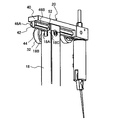
- FIG. 2 is a perspective view showing the upper ends of the radial movement arm 20 and the turning arm 18, and FIG. 3 is a cross-sectional view showing a cross section including the axis of the turning arm 18 and perpendicular to the radial direction. It is.
- the radial movement arm 20 has a quadrangular columnar arm body 40 extending along the radial direction.
- a quadrangular columnar rack member 42 extending along the radial direction is fixed to the side surface of the arm body 40 along the radial direction and on the side surface of the pivot arm 18 on the pivot axis side.
- a rack gear 44 that meshes with a pinion gear 60 described later is formed on the side surface of the rack member 42 in the radial direction and on the side surface of the swing arm 18 on the swing axis side.
- a rectangular columnar rail member 46A extending along the radial direction is provided on each of two side surfaces that are opposite to each other along the radial direction of the rack member 42 and that face the direction around the pivot axis of the pivot arm 18. 46B is fixed.
- the rail members 46A and 46B are engaged with the tip of the revolving arm 18 and supported so as to be movable in the radial direction.
- the distal end portion of the swivel arm 18 has projecting portions 18B and 18C that project in a bifurcated manner by a groove 18A formed along the radial direction, and rectilinear guides 50 and 52 are embedded in the projecting portions 18B and 18C. .
- Each of the linear guides 50 and 52 is formed with guide grooves 50A and 52A along the radial direction.
- the rack member 42 of the radial movement arm 20 is fitted into the groove 18A between the projecting portions 18B and 18C so as to be movable in the radial direction, and the rack member is inserted into each of the guide grooves 50A and 52A of the linear guides 50 and 52.
- Each of the 42 rail members 46A and 46B is fitted so as to be movable in the radial direction.
- the radial movement arm 20 is supported by the tip of the revolving arm 18 so as to be movable in the radial direction.
- a rotating member 54 extending along a direction perpendicular to the axial direction and the radial direction of the swing arm 18 is disposed in the groove 18A at the tip of the swing arm 18.
- Each of the protrusions 18B and 18C is formed with holes 56A and 56B into which the rotation member 54 is inserted, and bearings 58A and 58B are provided in the holes 56A and 56B, and the rotation member 54 is formed by the bearings 58A and 58B. It is supported rotatably.
- the rotation member 54 is formed with a pinion gear 60 at a portion facing the rack gear 44 formed on the rack member 42 of the radial movement arm 20, and the pinion gear 60 meshes with the rack gear 44.
- one end portion of the rotating member 54 is inserted through the hole 56A of the protruding portion 18B and protruded from the hole 56A, and the knob 32 is fixed to the protruding portion.
- the pinion gear 60 is rotated through the rotating member 54.
- the radial movement arm 20 moves in the radial direction via the engagement between the pinion gear 60 and the rack gear 44.
- the configuration of the radial movement mechanism of the radial movement arm 20 in the present embodiment is an example and may be an arbitrary configuration, and the radial movement arm 20 is moved in the radial direction by driving a motor. It may be. Similarly, the turning arm 18 may be turned by driving a motor.
- the carriage 16 is moved up and down by the movement mechanism of the carriage 16 in the up and down direction.
- the position of the tip of the probe 24B in the detector 24 in the vertical direction can be adjusted.
- the radial position of the radial movement arm 20 is adjusted and the diameter of the tip of the measuring element 24B is adjusted.
- the position in the direction (R-axis direction) can be adjusted.
- the turning angle of the turning arm 18 can be adjusted to adjust the angle of the axis of the measuring element 24B in the direction around the turning axis. it can.
- the tip of the probe 24B can be moved.
- the pivot axis is fixed with respect to the carriage 16 in this embodiment.
- the roundness measuring device 1 detects the roundness of each surface of the workpiece W having the cylindrical portion wa and the flange portion wb shown in FIG. A method of bringing the tip of the probe 24B of the instrument 24 into contact with each surface will be described.
- the work W is placed on the stage 12 so that the center axis of the work W is coaxial with the rotation axis ( ⁇ axis) of the stage 12.
- the vertical position of the carriage 16 in the detector support mechanism 13, the radial position of the radial movement arm 20, the turning angle of the turning arm 18, and the mounting angle of the detector 24 in the detector holder 22 are measured.
- the tip of the probe 24B is set so as to contact the measurement target surface, the displacement direction of the measurement probe 24B is perpendicular to the measurement target surface, and the biasing direction of the measurement probe 24B is directed to the measurement target surface. Is set as follows.
- the detector 24 has a detector holder 22 at an attachment angle so that the displacement direction of the probe 24B is the radial direction and the urging direction of the probe 24B is opposite to the direction toward the turning arm 18. To be held in.
- the vertical position of the carriage 16 and the radial position of the radial movement arm 20 are set to positions where the tip of the measuring element 24B comes into contact with the upper outer peripheral surface of the workpiece W that is the measurement target surface.
- the roundness of the upper outer peripheral surface of the workpiece W is measured by acquiring the displacement amount of the measuring element 24B detected by the detector 24 while rotating the workpiece W by the rotation of the mounting table 12. It can be carried out.
- the tip of the probe 24B can also be brought into contact with the upper outer peripheral surface by setting the turning angle (90 degrees) to be rearward and supporting the detector 24 so that the axial direction of the detector main body 24A is the front-rear direction. it can.
- the detector 24 has a detector holder 22 at an attachment angle so that the displacement direction of the probe 24B is the radial direction and the urging direction of the probe 24B is opposite to the direction toward the swivel arm 18.
- the position in the vertical direction of the carriage 16 and the position in the radial direction of the radial movement arm 20 are set to positions where the tip of the measuring element 24B comes into contact with the upper outer peripheral surface of the workpiece W that is the measurement target surface. .
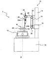
- the swing arm 18 is set at a swing angle (0 degree) that is upward in the vertical direction (Z-axis direction) as shown in FIGS. Is set.
- the detector 24 is fixed to the detector holder 22 so that the displacement direction of the probe 24B is the radial direction and the mounting angle is such that the urging direction of the probe 24B is directed to the turning arm 18. .
- the vertical position of the carriage 16 and the radial position of the radial movement arm 20 are set to positions where the tip of the measuring element 24B comes into contact with the inner peripheral surface of the workpiece W, which is the measurement target surface.
- the roundness of the inner peripheral surface of the workpiece W can be measured by acquiring the displacement of the probe 24B detected by the detector 24 while rotating the workpiece W by the rotation of the mounting table 12. It can be carried out.
- the outer peripheral surface (lower outer peripheral surface) which is the outer peripheral surface of the cylindrical portion wa of the workpiece W and is lower than the flange portion wb is the measurement target surface, as shown in FIGS. It is set to a turning angle (90 degrees) that is the backward direction in the front-rear direction.
- the detector 24 has a detector holder 22 at an attachment angle so that the displacement direction of the probe 24B is the radial direction and the urging direction of the probe 24B is opposite to the direction toward the turning arm 18. To be held in.
- the vertical position of the carriage 16 and the radial position of the radial movement arm 20 are set to positions where the tip of the measuring element 24B comes into contact with the lower outer peripheral surface of the workpiece W, which is the measurement target surface.
- the roundness of the lower outer peripheral surface of the workpiece W is measured by acquiring the displacement of the probe 24B detected by the detector 24 while rotating the workpiece W by the rotation of the mounting table 12. It can be performed.
- the tip of the probe 24B of the detector 24 can be brought into contact with an arbitrary cylindrical surface of the cylindrical or columnar workpiece W.
- the tip of the measuring element 24B can be brought into contact by adjusting the turning angle of the turning arm 18 even on a cylindrical surface (the lower outer peripheral face) where the measuring piece 24B cannot be contacted from above.
- the roundness measuring apparatus 1 can perform other measurements related to the shape accuracy of the workpiece surface as well as the roundness. For example, the flatness of each of the upper surface and the lower surface of the flange portion wb of the workpiece W in FIG. Etc. can also be measured.
- the swivel arm 18 is set to a swivel angle (90 degrees) that is backward in the front-rear direction. .
- the detector 24 is fixed to the detector holder 22 at an attachment angle so that the displacement direction of the probe 24B is in the vertical direction and the urging direction of the probe 24B is downward.
- the vertical position of the carriage 16 and the radial position of the radial movement arm 20 are set to positions where the tip of the measuring element 24B comes into contact with the upper surface of the flange portion wb that is the measurement target surface.
- the flatness of the upper surface of the flange portion wb can be measured by acquiring the displacement of the probe 24B detected by the detector 24 while rotating the workpiece W by the rotation of the mounting table 12. .
- the swing arm 18 is set to a swing angle (90 degrees) that is backward in the front-rear direction. .
- the detector 24 is fixed to the detector holder 22 so that the displacement direction of the probe 24B is in the vertical direction and the urging direction of the probe 24B is upward.
- the vertical position of the carriage 16 and the radial position of the radial movement arm 20 are set so that the tip of the measuring element 24B comes into contact with the lower surface of the flange portion wb that is the measurement target surface.
- the flatness of the lower surface of the flange portion wb can be measured by acquiring the displacement amount of the probe 24B detected by the detector 24 while rotating the workpiece W by the rotation of the mounting table 12. .
- FIG. 12 and 13 are front views showing the detector support mechanism 102 in the known roundness measuring apparatus 100.
- FIG. 1 the same or similar components as those of the roundness measuring apparatus 1 of the present embodiment are denoted by the same reference numerals, description thereof is omitted, and different constituent elements are provided. Only will be described.
- the radial movement arm 104 extending along the radial direction is supported by the carriage 16 so as to be movable in the radial direction.
- the turning arm 18 is connected to the tip of the radial movement arm 104 so as to be turnable around a turning axis along the radial direction.
- the base end portion of the radial fixed arm 106 extending along the radial direction is fixed to the distal end portion of the turning arm 18 instead of the radial movement arm 20 of the present embodiment.
- the detector holder 22 is fixed to the distal end portion of the radial fixing arm 106.
- the turning arm 18 is set to a turning angle (0 degree) that is upward in the vertical direction (Z-axis direction).
- the measuring element 24B is used as shown in FIG. 13 is set to be opposite to the direction toward the swivel arm 18, and when the inner peripheral surface is the measurement target surface, the biasing direction of the probe 24B is the swivel arm as shown in FIG. The direction is set to be opposite to the direction toward 18.
- the vertical position of the carriage 16 and the radial position of the radial movement arm 104 are set to positions where the tip of the measuring element 24B comes into contact with the outer peripheral surface or inner peripheral surface of the workpiece W that is the measurement target surface.
- the workpiece W shown in FIGS. 12 and 13 is a workpiece having the maximum outer diameter and the minimum inner diameter that can be measured by the roundness measuring apparatus 100, and the tip of the measuring element 24B contacts the outer peripheral surface of the workpiece W.
- it is set at a position farthest from the rotation axis ( ⁇ axis) of the mounting table 12 in a range in which the radial movement arm 104 can move in the radial direction.
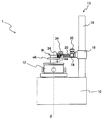
- FIGS. 14 and 15 show the maximum outer diameter and the minimum inner diameter that can measure the workpiece W having the same outer diameter and inner diameter as those in FIGS. 12 and 13 in the roundness measuring apparatus 1 of the present embodiment.
- the detector support mechanism 13 when designed as a workpiece is shown. That is, when the tip of the measuring element 24B is brought into contact with the outer peripheral surface of the workpiece W, as shown in FIG. 14, the rotation axis ( ⁇ of the mounting table 12 within the range in which the radial movement arm 20 is movable in the radial direction is used. It is set at the position farthest from the axis.
- the roundness measuring apparatus 1 of the present embodiment can be reduced in size.
- the detector support mechanism 102 of the roundness measuring apparatus 100 in FIG. 12 it is necessary to provide a space in which the radial fixing arm 106 is interposed between the detector 24 (the outer peripheral surface of the workpiece W) and the column 14.
- the detector support mechanism 13 of the roundness measuring device 1 of the present embodiment in FIG. 14 the detector 24 is moved to the vicinity of the column 14 by narrowing the distance between the detector 24 and the swivel arm 18. Can be made. Therefore, in the roundness measuring device 1 of the present embodiment in FIG. 14, it is not necessary to provide a space for interposing the radial fixing arm 106, and the size of the base 10 in the left-right direction is reduced.
- the roundness measuring apparatus 1 of the present embodiment in FIG. The smallest possible inner diameter can be measured. Therefore, the roundness measuring apparatus 1 of the present embodiment is not limited to the size of the inner diameter that can be measured with respect to the roundness measuring apparatus 100 in FIGS.
- the radial arm is used as the configuration of the detector holder support mechanism that supports the detector holder 22 via the radially extending arm (radial arm) supported by the tip of the swivel arm 18.
- the detector 24 detector holder 22
- the measurement space and the base 10 can be reduced in size,
- the size measuring device 1 is miniaturized.
- the base end of the radial fixing arm 120 extending along the radial direction is fixed to the distal end of the swivel arm 18.
- the detector holder 22 may be configured to be movable in the radial direction with respect to the radial direction fixed arm 120.
- the mechanism for moving the detector holder 22 in the radial direction may be any configuration, and may be manually moved or moved by driving a motor.
- W ... Workpiece 1,100 ... Roundness measuring device, 10 ... Base, 12 ... Mount table, 13, 102 ... Detector support mechanism, 14 ... Column, 16 ... Carriage, 18 ... Swivel arm, 20, 104 ... Radial moving arm, 22 ... Detector holder, 24 ... Detector, 24A ... Detector body, 24B ... Measuring element, 106 ... Radial direction fixed arm
Abstract
Un dispositif de mesure de rotondité 1 selon la présente invention comporte une base 10, une plateforme 12 qui est disposée sur la base 10 et sur laquelle est placée une pièce à traiter W, une colonne 14 disposée verticalement sur la base 10, un chariot 16 supporté de manière à être capable de se déplacer le long de la colonne 14, un bras rotatif 18 supporté par le chariot 16 de manière à être capable de tourner autour d'un axe de rotation dans la direction radiale (direction gauche-droite), un bras mobile dans la direction radiale 20 supporté de manière à être capable de se déplacer dans la direction radiale, et un support de détecteur 22 fixé à l'extrémité avant du bras mobile dans la direction radiale 20. Un détecteur 24 est fixé sur le support de détecteur 22, et la position du détecteur dans la direction radiale est réglée par le déplacement dans la direction radiale du bras mobile dans la direction radiale 20.
Priority Applications (1)
| Application Number | Priority Date | Filing Date | Title |
|---|---|---|---|
| EP16743094.1A EP3239654B1 (fr) | 2015-01-28 | 2016-01-12 | Dispositif de mesure de rotondité |
Applications Claiming Priority (2)
| Application Number | Priority Date | Filing Date | Title |
|---|---|---|---|
| JP2015014383A JP5943099B1 (ja) | 2015-01-28 | 2015-01-28 | 真円度測定装置 |
| JP2015-014383 | 2015-01-28 |
Publications (1)
| Publication Number | Publication Date |
|---|---|
| WO2016121490A1 true WO2016121490A1 (fr) | 2016-08-04 |
Family
ID=56244722
Family Applications (1)
| Application Number | Title | Priority Date | Filing Date |
|---|---|---|---|
| PCT/JP2016/050715 WO2016121490A1 (fr) | 2015-01-28 | 2016-01-12 | Dispositif de mesure de rotondité |
Country Status (3)
| Country | Link |
|---|---|
| EP (1) | EP3239654B1 (fr) |
| JP (1) | JP5943099B1 (fr) |
| WO (1) | WO2016121490A1 (fr) |
Cited By (3)
| Publication number | Priority date | Publication date | Assignee | Title |
|---|---|---|---|---|
| CN108413858A (zh) * | 2018-06-07 | 2018-08-17 | 中国计量大学 | 一种接触式圆珠笔球珠尺寸形状测量装置及测量方法 |
| CN113624188A (zh) * | 2021-08-27 | 2021-11-09 | 安庆振宜机动车零部件再制造有限公司 | 一种用于汽车零部件真圆度的检测装置 |
| CN115847441A (zh) * | 2022-12-19 | 2023-03-28 | 杭州电子科技大学 | 一种基于轴类工件测量机器人 |
Families Citing this family (2)
| Publication number | Priority date | Publication date | Assignee | Title |
|---|---|---|---|---|
| KR101834372B1 (ko) | 2016-11-14 | 2018-03-05 | 한호산업(주) | 기어부품의 표면결함 측정장치 |
| CN108955491B (zh) * | 2018-07-30 | 2020-08-25 | 陕西柴油机重工有限公司 | 圆度仪测量活塞型线的多功能底盘工装及其测量方法 |
Citations (3)
| Publication number | Priority date | Publication date | Assignee | Title |
|---|---|---|---|---|
| JP2008070181A (ja) * | 2006-09-13 | 2008-03-27 | Mitsutoyo Corp | 真円度測定装置較正治具および真円度測定装置の較正方法 |
| JP2011208994A (ja) * | 2010-03-29 | 2011-10-20 | Mitsutoyo Corp | 真円度測定機 |
| JP2013108757A (ja) * | 2011-11-17 | 2013-06-06 | Tokyo Seimitsu Co Ltd | 真円度測定装置 |
Family Cites Families (3)
| Publication number | Priority date | Publication date | Assignee | Title |
|---|---|---|---|---|
| US4679326A (en) * | 1984-11-21 | 1987-07-14 | Mitutoyo Mfg. Co., Ltd. | Height gauge |
| JP5336279B2 (ja) * | 2009-07-08 | 2013-11-06 | 株式会社ミツトヨ | 表面性状測定装置および真円度測定装置 |
| US8650939B2 (en) * | 2009-10-13 | 2014-02-18 | Mitutoyo Corporation | Surface texture measuring machine and a surface texture measuring method |
-
2015
- 2015-01-28 JP JP2015014383A patent/JP5943099B1/ja active Active
-
2016
- 2016-01-12 EP EP16743094.1A patent/EP3239654B1/fr active Active
- 2016-01-12 WO PCT/JP2016/050715 patent/WO2016121490A1/fr active Application Filing
Patent Citations (3)
| Publication number | Priority date | Publication date | Assignee | Title |
|---|---|---|---|---|
| JP2008070181A (ja) * | 2006-09-13 | 2008-03-27 | Mitsutoyo Corp | 真円度測定装置較正治具および真円度測定装置の較正方法 |
| JP2011208994A (ja) * | 2010-03-29 | 2011-10-20 | Mitsutoyo Corp | 真円度測定機 |
| JP2013108757A (ja) * | 2011-11-17 | 2013-06-06 | Tokyo Seimitsu Co Ltd | 真円度測定装置 |
Cited By (5)
| Publication number | Priority date | Publication date | Assignee | Title |
|---|---|---|---|---|
| CN108413858A (zh) * | 2018-06-07 | 2018-08-17 | 中国计量大学 | 一种接触式圆珠笔球珠尺寸形状测量装置及测量方法 |
| CN113624188A (zh) * | 2021-08-27 | 2021-11-09 | 安庆振宜机动车零部件再制造有限公司 | 一种用于汽车零部件真圆度的检测装置 |
| CN113624188B (zh) * | 2021-08-27 | 2024-03-15 | 安庆振宜机动车零部件再制造有限公司 | 一种用于汽车零部件真圆度的检测装置 |
| CN115847441A (zh) * | 2022-12-19 | 2023-03-28 | 杭州电子科技大学 | 一种基于轴类工件测量机器人 |
| CN115847441B (zh) * | 2022-12-19 | 2023-07-28 | 杭州电子科技大学 | 一种基于轴类工件测量机器人 |
Also Published As
| Publication number | Publication date |
|---|---|
| EP3239654B1 (fr) | 2018-11-14 |
| JP5943099B1 (ja) | 2016-06-29 |
| EP3239654A1 (fr) | 2017-11-01 |
| JP2016138831A (ja) | 2016-08-04 |
| EP3239654A4 (fr) | 2017-11-08 |
Similar Documents
| Publication | Publication Date | Title |
|---|---|---|
| WO2016121490A1 (fr) | Dispositif de mesure de rotondité | |
| US7197835B2 (en) | Detector supporting mechanism | |
| JP2013164273A (ja) | 内径測定装置 | |
| US9316476B2 (en) | Profile measuring instrument, adjusting method for profile measuring instrument, and profile measuring method | |
| JP2006231509A (ja) | プログラム制御の工作機械を測定する方法 | |
| JP5324510B2 (ja) | 真円度測定機 | |
| JP5971445B1 (ja) | 真円度測定装置 | |
| JP2006194739A (ja) | 被測定物の振れ測定装置及び方法 | |
| JP5705092B2 (ja) | 真円度測定装置 | |
| EP2016366B1 (fr) | Appareil metrologique de mesure de caracteristiques de surface | |
| US20230032119A1 (en) | Roundness measuring machine | |
| JP2017067512A (ja) | 外径測定器およびそれを用いた研削装置 | |
| JP5752313B2 (ja) | 真円度測定装置 | |
| JP2011232173A (ja) | 寸法測定装置及び寸法測定方法 | |
| JP2010271047A (ja) | 光学式やタッチプローブ型の測定機構部及び軸体支持機構部を有する軸体測定装置及び該装置による軸体の諸元及び精度の測定方法 | |
| JP3654744B2 (ja) | 真円度測定機 | |
| JP6601939B2 (ja) | 測長装置 | |
| JP4437430B2 (ja) | 円すい面形状測定装置 | |
| JP6537950B2 (ja) | ゲージ検査機 | |
| JP2021056135A (ja) | 高さ測定機 | |
| KR101644914B1 (ko) | 밀링 지그의 각도 측정 장치 | |
| GB2493786A (en) | Merological apparatus | |
| JP5819019B2 (ja) | 真円度測定装置および真円度測定方法 | |
| JP2005172739A (ja) | 歯溝振れ量の測定装置および測定方法 | |
| JPH05141959A (ja) | ねじ有効径部振れ測定装置 |
Legal Events
| Date | Code | Title | Description |
|---|---|---|---|
| 121 | Ep: the epo has been informed by wipo that ep was designated in this application |
Ref document number: 16743094 Country of ref document: EP Kind code of ref document: A1 |
|
| REEP | Request for entry into the european phase |
Ref document number: 2016743094 Country of ref document: EP |
|
| NENP | Non-entry into the national phase |
Ref country code: DE |